Printability of 3D Printed Hydrogel Scaffolds: Influence of Hydrogel Composition and Printing Parameters


1
Division of Biomedical Engineering, College of Engineering, University of Saskatchewan, Saskatoon, SK S7N 5A9, Canada
2
Department of Mechanical Engineering, College of Engineering, University of Saskatchewan, Saskatoon, SK S7N 5A9, Canada
3
School of Engineering, ICAM Toulouse, 31300 Toulouse, Haute-Garonne, France
*
Authors to whom correspondence should be addressed.
Appl. Sci. 2020, 10(1), 292; https://doi.org/10.3390/app10010292
Submission received: 26 November 2019
/
Revised: 16 December 2019
/
Accepted: 19 December 2019
/
Published: 31 December 2019
(This article belongs to the Special Issue Bioprinting Scaffolds for Tissue Engineering Applications)
Abstract
:Extrusion-based bioprinting of hydrogel scaffolds is challenging due to printing-related issues, such as the lack of capability to precisely print or deposit hydrogels onto three-dimensional (3D) scaffolds as designed. Printability is an index to measure the difference between the designed and fabricated scaffold in the printing process, which, however, is still under-explored. While studies have been reported on printing hydrogel scaffolds from one or more hydrogels, there is limited knowledge on the printability of hydrogels and their printing processes. This paper presented our study on the printability of 3D printed hydrogel scaffolds, with a focus on identifying the influence of hydrogel composition and printing parameters/conditions on printability. Using the hydrogels synthesized from pure alginate or alginate with gelatin and methyl-cellulose, we examined their flow behavior and mechanical properties, as well as their influence on printability. To characterize the printability, we examined the pore size, strand diameter, and other dimensions of the printed scaffolds. We then evaluated the printability in terms of pore/strand/angular/printability and irregularity. Our results revealed that the printability could be affected by a number of factors and among them, the most important were those related to the hydrogel composition and printing parameters. This study also presented a framework to evaluate alginate hydrogel printability in a systematic manner, which can be adopted and used in the studies of other hydrogels for bioprinting.

1. Introduction
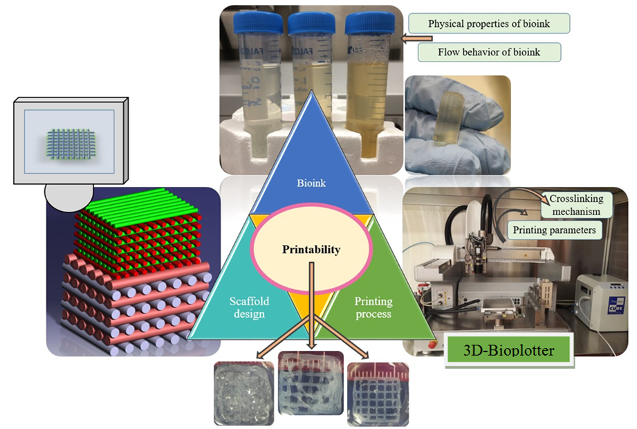
Extrusion-based bioprinting is an additive manufacturing (AM) technique used for various tissue engineering applications (Figure 1) [1]. Many studies have been carried out to create hydrogel scaffolds using this technique [2,3]. Generally speaking, computer-aided design (CAD) is used to deposit biomaterials [4]. However, scaffolds are rarely fabricated exactly according to the CAD model. That is why the printability index is important as an element showing the difference between the scaffold design (typically in a CAD model) and the printed scaffold. Three dimensional (3D) printability of a hydrogel biomaterial is defined as the ability of a hydrogel to form and maintain a reproducible 3D structure with dimensional integrity. Although the range of accuracy for extrusion-based machines is in the order of a micron, there is still a challenge when it comes to shaping the fidelity and printability of scaffolds bio-fabricated using the extrusion-based technique.
The printability can influence other interrelated factors, such as the morphology and mechanical properties of scaffolds. Consequently, it can affect cell response [5], and it is well-accepted that the mechanical properties of scaffolds can influence cell faith [6]. Hence, it is important to study elements that can influence printability. Although there are a few studies on the printability of different biomaterials, the real picture and definition of printability remain unclear and there are fundamental questions about how to map the relationships between printability and other interrelated factors such as biomaterial and fabrication. For example, in some studies, the flow behavior of biomaterials was considered to evaluate printability [7,8]. In these studies, only the physical and rheological characteristics of materials were investigated [9]. In another study, the influence of ionic crosslinkers on printability was investigated without considering other factors [10]. In some studies, only printing parameters were investigated as critical factors influencing printability [2,11]. In another study, the gelation properties of materials during the printing process were studied to achieve a mechanically stable structure [12]. Murphy et al. studied gelation time, swelling, and the printability of various groups of hydrogels [13]. In another study, analytical methods were implemented to check the printability of materials [14]. Kyle et al. reported that printability is a matter of rheology, biomaterial composition, nozzle variables, pore and filament dimensions, geometry, and printing angle [15]. Hence, considering only one of the factors is not a systematic approach to improving printability. As mentioned, different studies have specifically investigated the effect of some factors on printability. However, there is no clear picture of printability considering the interrelated factors influencing printability. In this study, rheological properties, printing parameters, and printing conditions were investigated systematically to map the relationship between these parameters and printability, rather than considering each factor individually. As such, more studies should be performed in this area to define and establish novel approaches to define and measure printability. The key question of this study related to how to measure printability [15].
Alginate is one of the hydrogels used for the biofabrication of scaffolds used for tissue engineering applications, as reported in numerous studies [16,17,18,19,20,21,22,23]. Specifically, one of the approaches to improve the printability of alginate scaffolds fabricated by extrusion-based bioprinting method is to mix alginate with other types of hydrogels [24]. Gelatin is one of the hydrogels usually mixed with alginate. Gelatin is a natural polymer derived from collagen and it has a cell-friendly environment and this is one of the reasons for mixing alginate with this biomaterial [12]. Methylcellulose (MC) is another biocompatible hydrocarbon polymer commonly used in scaffold fabrication due to its high hydrophilicity and water absorption, essential for nutrient delivery to the cells [25]. Hydrogels composed of multiple biomaterials have also been used in scaffold construction. For example, one study analyzed the properties of cell substrates composed of a scaffold containing both gelatin and alginate, and they found these scaffolds to have high water retention rates [26]. The result suggests that combining different biomaterials may be a way to manipulate the scaffold characteristics and allow for better control in achieving desired scaffold functions.
This study aims to present a clear picture of printability, to identify factors that can affect it, and to propose methods to measure 3D printability of hydrogel scaffolds with an alginate matrix. There are some studies on the effect of the flow behavior of biomaterials [27], ink consistency [7], and hydrogel mechanical characteristics [9] on printability. Nevertheless, little attention has been paid to the effect of printing parameters of scaffolds made from a mixture of hydrogels [2]. Here, the effect of hydrogel composition (alginate, alginate-gelatin, alginate-gelatin-MC, and alginate-MC) on the swelling, mechanical, and degradation properties was tested over time. Then, a systematic study was implemented by characterizing the biomaterial flow behavior, as well as the 2D and 3D printability of hydrogels with different compositions. Finally, a linear regression model was developed to map the relationships between various biomaterial-related and fabricated-related elements affecting printability.
2. Materials and Methods
2.1. Preparation of Hydrogels
Medium viscosity sodium alginate from brown algae (Sigma-Aldrich Canada Ltd., P-code 1001172534, with a molecular weight of 80,000–120,000 g/mol), was used for the preparation of a 3% w/v alginate (Group 1) using distilled water. Gelatin from porcine skin, Type A, Bioreagent, (Sigma-Aldrich Canada Ltd.) was used for the preparation of a 2% w/v alginate and 1% w/v gelatin solution (Group 2). MC, phosphate buffer saline, and calcium chloride were obtained from Sigma-Aldrich Canada (Oakville, ON, Canada). 1.5% w/v alginate, 1% w/v gelatin, and 0.5% w/v MC were mixed together as Group 3. Group 4 consisted of 1.5% w/v alginate and 1.5% w/v MC solution. For bulk gel experiments, the hydrogels were pipetted into molds to a height of 4 mm and incubated with 50 mM calcium chloride at room temperature for cross-linking.
For ease of discussion, the different groups were named herein. Group 1 referred to 3% (w/v) alginate while Group 2 referred to 2% (w/v) alginate and 1% (w/v) gelatin. The third group included 1.5% (w/v) alginate, 1% (w/v) gelatin, and 0.5% (w/v) MC (Group 3). The last group included the 1.5% (w/v) alginate and 1.5% (w/v) methylcellulose (Group 4). To have a uniform solution for printing, we stirred the prepared solutions, centrifuged them, and then kept them in a refrigerator to get rid of bubbles during the preparation procedure to ensure complete hydration. In addition, the solutions were kept in the nozzle for 20 min for a uniform solution with a stable temperature in the printing head before starting the printing process.
2.2. Scaffold Fabrication
A 3D Bioplotter (EnvisionTEC GmbH, Gladbeck, Germany) was used to print scaffolds of 11 × 11 × 11 mm. All groups of hydrogels were deposited using a 200 µm needle inner diameter. Magics13 EnvisionTEC software and Bioplotter RP software were used for the CAD model generation and slicing, respectively. Scaffolds were fabricated layer-by-layer, while hydrogel filaments were deposited into a calcium chloride (CaCl2) bath in a 12-well plate. The filament width, pore sizes, pore area, and the perimeter of the scaffolds were measured using ImageJ® software (National Institute of Health, Gaithersburg, MD, USA). To check the uniformity of the fabricated scaffolds, at least, 3 scaffolds were printed and evaluated in terms of pore size and strand diameter.
2.3. Testing Hydrogel Construct Swelling Properties
The initial weights of the hydrogel scaffolds were measured after removing them from the crosslinker solution, and the scaffolds were then incubated in 10 mM PBS solution at 37 °C and 5% carbon dioxide. The weights of the samples were measured again after 1 h, 3 h, 12 h, 3 days, 7 days, and 14 days, for any change in mass due to swelling. A Kimwipe was used to eliminate excess or free liquid from the scaffold before weighing each sample. The swelling of the composite scaffolds was calculated using the following equation (Equation (1)):
where Wt is the hydrogel weight at the specific time, and W0 is the hydrogel weight at time 0 h.
2.4. Testing the Compressive Strength of the Hydrogel Constructs
The hydrogel scaffolds were tested for compression strength using a compressive testing instrument from BOSE (load cell capacity: 20 Newtons). This device measured the forces required to compress a sample to a series of displacements until a maximum displacement of 2 mm was reached. The area and height of the scaffolds were measured using ImageJ® software before mechanical testing, and the resulting data were used to plot the stress-strain curves for each construct. The elastic modulus was determined by finding the slope of the linear portion of the stress-strain curve.
2.5. Testing Hydrogel Construct Degradation Properties
Scaffolds were freeze-dried and then weighed to determine their initial masses. To obtain the degraded scaffolds, we incubated the samples in 10 mM PBS solution at 37 °C and 5% carbon dioxide for 7, 14, 21, and 28 days. The PBS solution was taken out of the samples and the samples were freeze-dried and weighed again using a digital scale. The hydrogel degradation was calculated using the following equation:
where WFDt is the freeze-dried hydrogel weight at a given time, and WFD0 is the freeze-dried hydrogel weight at the time 0.
2.6. Flow Behavior Tests
The flow behaviors of groups 1 to 4 were investigated at 37 °C. A Brookfield Ultra III Rheometer with the CP-41 spindle was used for the testing. The shear rate, shear stress, viscosity, and percentage of torque have been measured at various rotational speeds.
2.7. Printability Studies on Printing Parameters and Condition
Two dimensional (2D) studies were performed to check the printability of the scaffolds by printing lines (scaffolds with two layers). Likewise, follow-up studies were carried out to check the 3D printability of different groups by printing 3D scaffolds. In the flowing subsections, the experimental design on how to evaluate the effect of air pressure, nozzle speed, offset, and pattern selection on printability is discussed.
2.7.1. Air Pressure
For the set of either 2D or 3D studies, air pressure (0.1 to 0.8 bar) and temperature (37, 45, and 55 °C) were subjected to changes while other printing parameters such as nozzle speed and temperature were maintained constant.
2.7.2. Nozzle Speed
For the second set of experiments, nozzle speed was changed, starting from 4 mm/s for several pressures (0.1 to 0.4 bar). For this, the scaffolds crosslinked mechanically and chemically using a cold bed and CaCl2, respectively (except for Group 1, crosslinked chemically). For groups crosslinked physically, the printing temperature was kept at 37 °C while the printing bed temperature was 10 °C (pressure: 0.1–0.5 bar, minimum nozzle speed of 10 mm/s). For all groups crosslinked chemically, the minimum nozzle speed was 4 mm/s (pressure: 0.1 to 0.4 bar) and Group 1 was printed at 24 °C while other groups were printed at 37 °C.
2.7.3. Offset
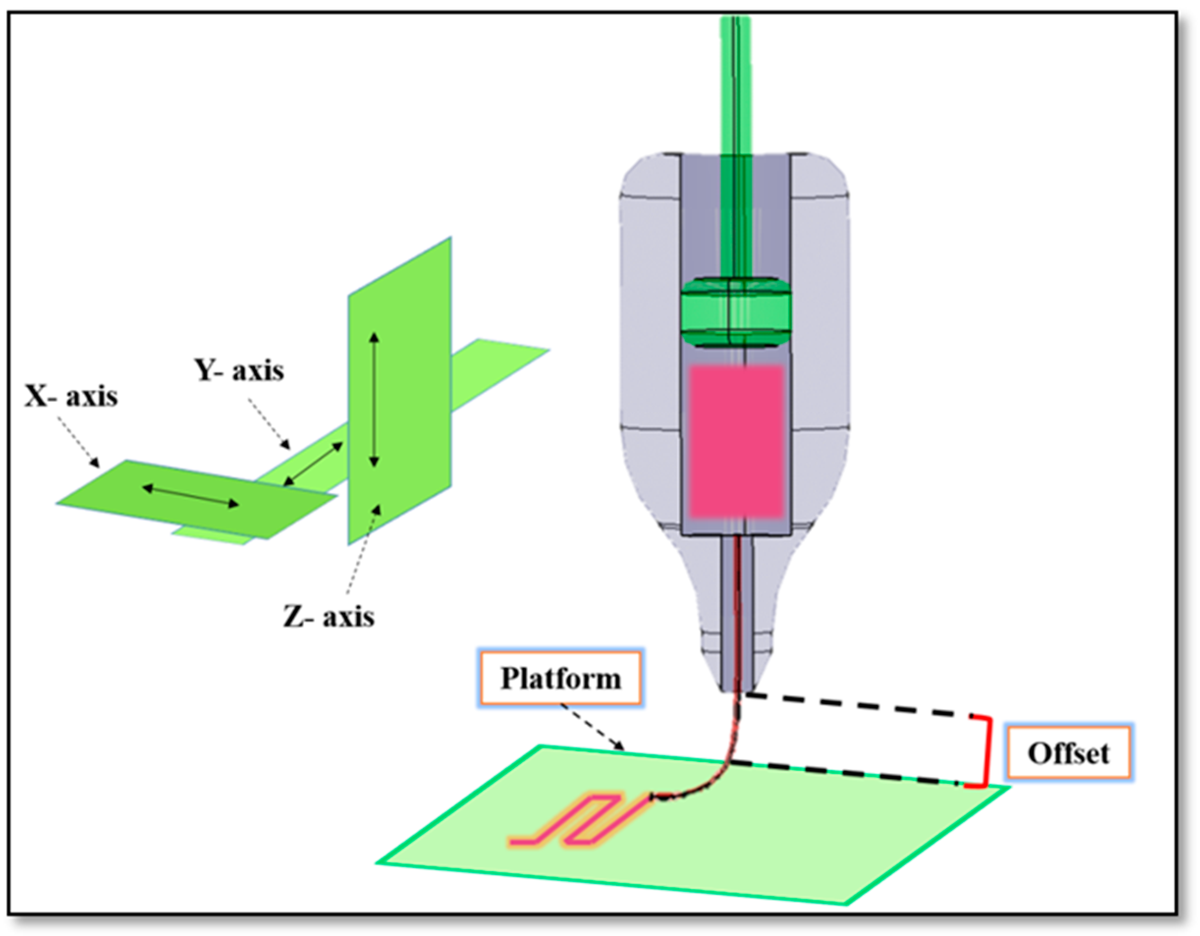
For the third set of experiments, offset was the variable (−0.08 to 0.08 mm), and the selected temperature was the same as the one for the previous set of experiments (negative values were as per calibration and did not mean any substrate scratching). The offset is the distance from the nozzle to the build platform (Figure 1). It was analyzed to determine the influence of the offset on the line width. The nozzle speed was maintained at 35 mm/s (pressure: 0.1 and 0.2 bar).
2.7.4. Angular Pattern Printing
In another part of the printability investigation, scaffolds with various angular patterns were printed and evaluated from a printability perspective. For this, scaffolds with angular patterns of 0–25°, 0–45°, and 0–90° were printed. Pressure and nozzle speed were maintained between 0.1 and 0.2 bar and 35 to 40 mm/s, respectively. The temperature was maintained as per Section 2.7.2.
2.8. Printability Evaluation
In this study, different evaluations were performed to show methods of how to measure printability. For this, firstly, a standard diameter of strands (Ds) was calculated and compared with the experimental strand diameter. For this, the following equations were used:
where , Q, and Ds are density, flow rate, and standard strand diameter, respectively. Here, different solutions for groups 1 to 4 were purged for a limited time, and then purged materials were weighted using the Sartorius Scale (model 225d). From Equation (1), the volume can be calculated and then using Equations (2) and (3), the flow rate and standard strand diameter can be calculated, respectively, for different nozzle speeds. For this evaluation, the pressure was maintained between 0.2 to 0.4 bar and the temperature was the same as the one reported in Section 2.7.2. Based on Equation (3), strand printability was defined as:
where Dexp. is experimental strand diameter. In another evaluation, pore printability was checked as described in Reference [8]. The following equation was used for this purpose.
where and are the area and perimeter of a pore of a scaffold. In the last evaluation, pore irregularity was defined as:
where Ix,y is the irregularity of the geometry of scaffolds in different directions of X and Y. (x,y)th shows the ideal length of a scaffold in the X and Y directions as per CAD design, while (x,y)exp. represents the experimental lengths in these directions.
2.9. Statistical Significance
Statistical significance was calculated by performing a student’s t-test. For each set of experiments, three replicas were considered and data were presented as a mean ± standard deviation. Significant differences were shown with p-values of p < 0.05 and p < 0.01. Using Minitab® 17.1 software, a linear regression model was developed with two-sided intervals of confidence with 95% value.
3. Results
3.1. Swelling Properties, Degradation, and Mechanical Characterization
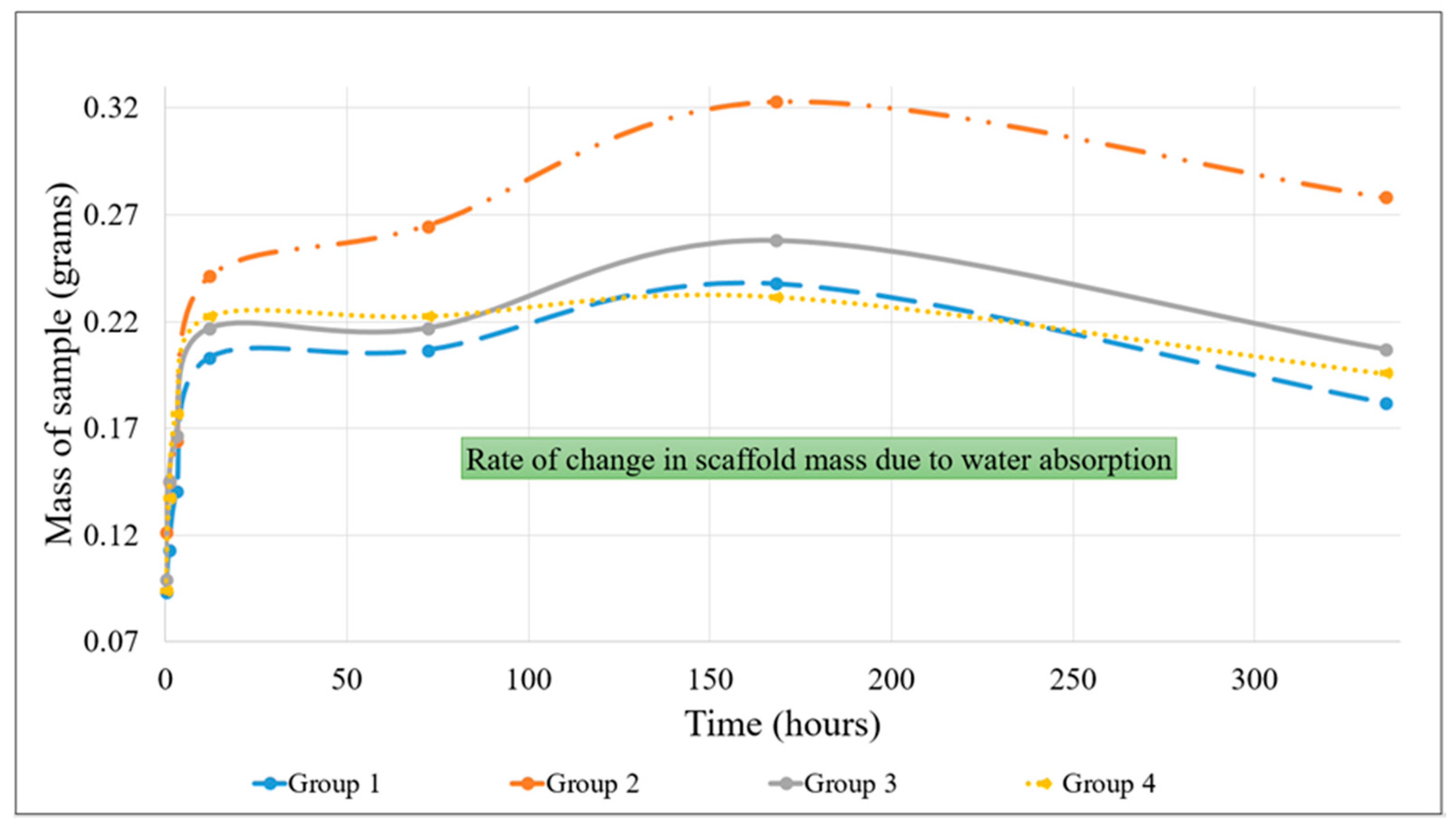
The swelling properties of hydrogels are indicative of the ability of nutrients and wastes to be exchanged between the environment and cells that would be incorporated into the gels for the production of synthetic tissue. All samples in this study were incubated in PBS to assess the rate of water absorption over time. The change in mass of the hydrogels due to water absorption indicated a trend shown in Figure 2.
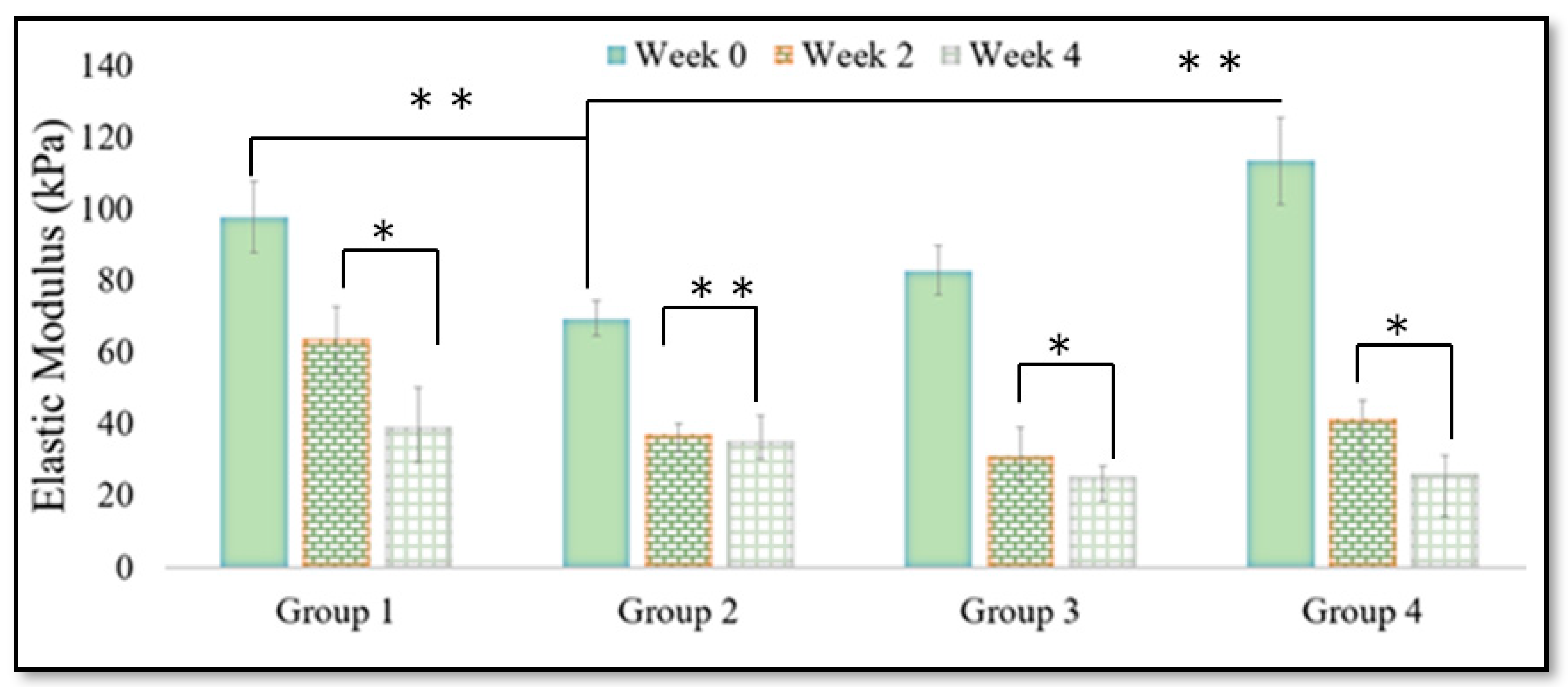
Group 1 showed a 155.10% swelling, Group 2 showed 165.95% swelling, Group 3 showed 160.93% swelling, and Group 4 showed 146.75% swelling after 168 h of incubation with PBS. According to the data, Group 2’s hybrid hydrogels showed the highest rate of absorption indicated by the highest change in mass over time of incubation. The degradation rate of each sample was also measured by observing the change in mass of the samples after immersion in PBS over time. The pure alginate samples (Group 1), Group G, Group 3, and Group 4 showed 32.53%, 13.33%, 40.00%, and 19.70% degradation, respectively, over time incubated in PBS. PBS has been used widely to evaluate the degradation rate of scaffolds, as reported in References [11,28,29,30]. Notably, as future work, other solutions such as fetal bovine serum and penicillin-streptomycin contained medium can be used to check the degradation rate of scaffolds. The alginate-gelatin-MC and pure alginate gels showed the greatest rate of degradation. The compressive strength of all groups was determined by finding the elastic modulus of each sample over weekly intervals of time, and the results are shown in Figure 3.
The elastic moduli of Group 1’s samples were 97.7 kPa, 63.8 kPa, and 39.1 kPa, while for Group 2’s samples, it was 69.4 kPa, 37.1 kPa, and 35.2 kPa during the 0, 2, and 4 weeks of incubation in PBS, respectively. The values for Group 3’s samples were 82.85 kPa, 31 kPa, and 25.4 kPa, and the values for Group 4’s samples were 113.3 kPa, 41.45 kPa, and 26.1 kPa. The results indicated that there was a decline in the compressive strength of each of the hydrogels. This was especially evident in the first two weeks. After the first two weeks of immersion, the decline in compressive strength was more pronounced in pure alginate gels than the composite polymer samples. Furthermore, the scaffolds of Group 4 had a significantly higher elastic modulus compared to the hybrid constructs containing gelatin.
3.2. Flow Behavior Results
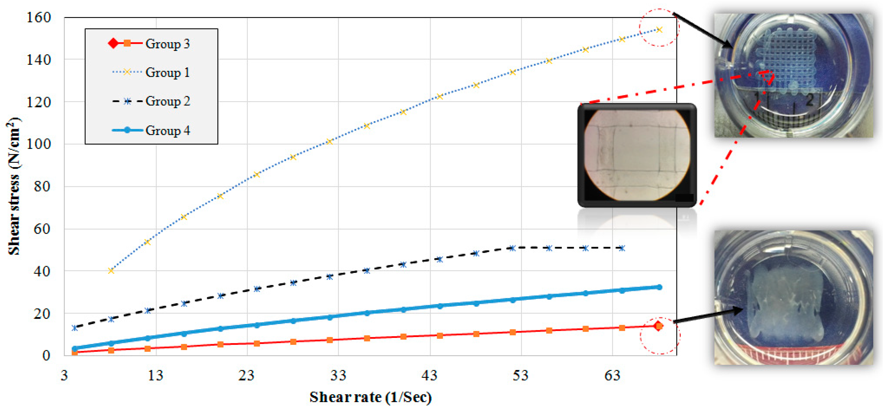
The flow behavior of all four groups was analyzed, and Figure 4 shows the results of shear rate versus shear stress. At the same shear rate, Group 1 showed higher shear stresses. Both groups 3 and 4, which contained MC, had a linear stress/strain behavior while groups 1 and 2 showed a non-Newtonian behavior.
Based on the results obtained from Figure 4, the viscosity was calculated and the results showed high viscosity of Group 1 followed by groups 2, 4, and 3. It was reported that 300 to 30,000 cps is a suitable range of viscosity for printable biomaterials [2]. Our results showed that all groups, except for Group 3, were in this range (Table 1).
3.3. Effect of Printing Parameters on 2D Printability
3.3.1. Pressure Test
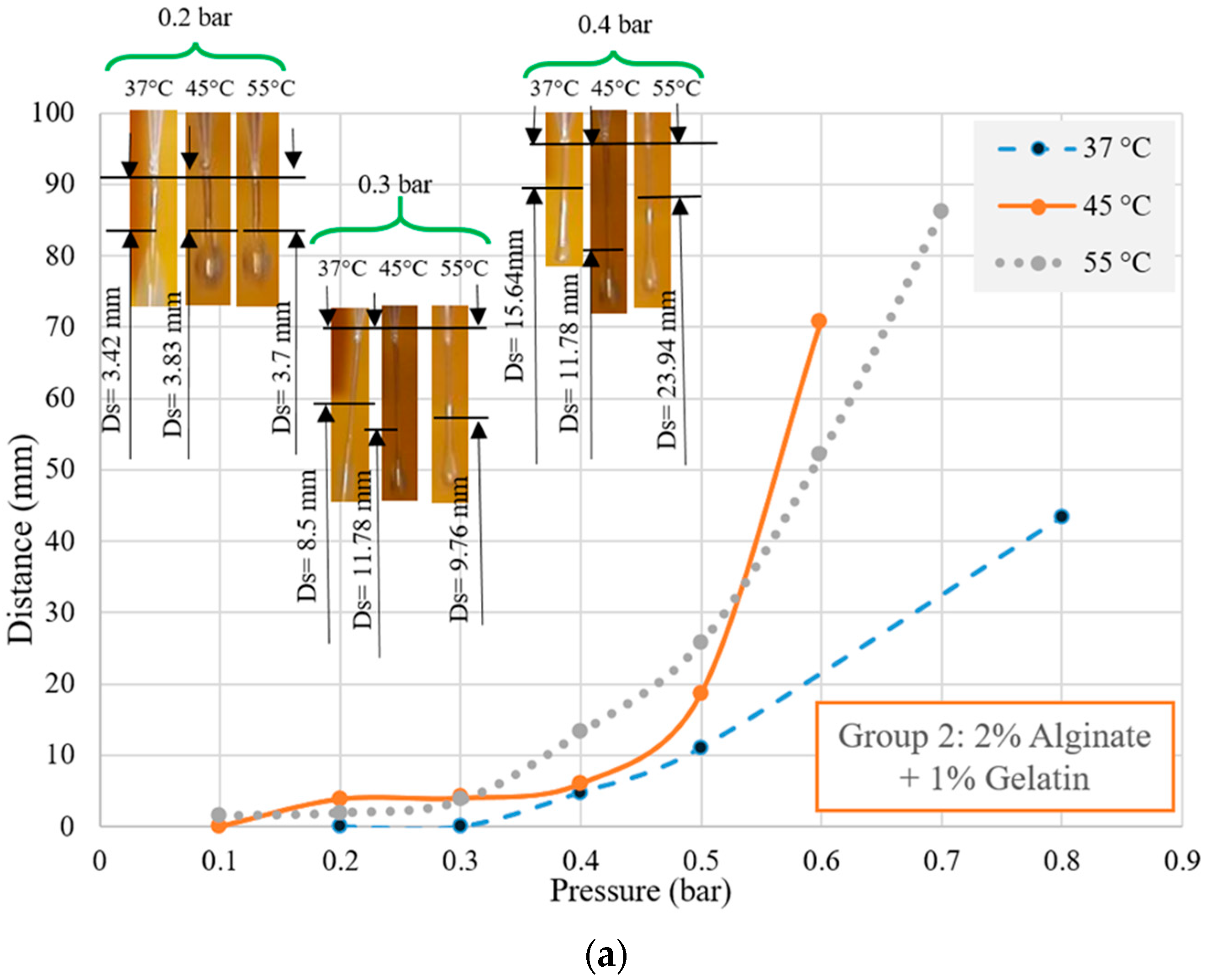
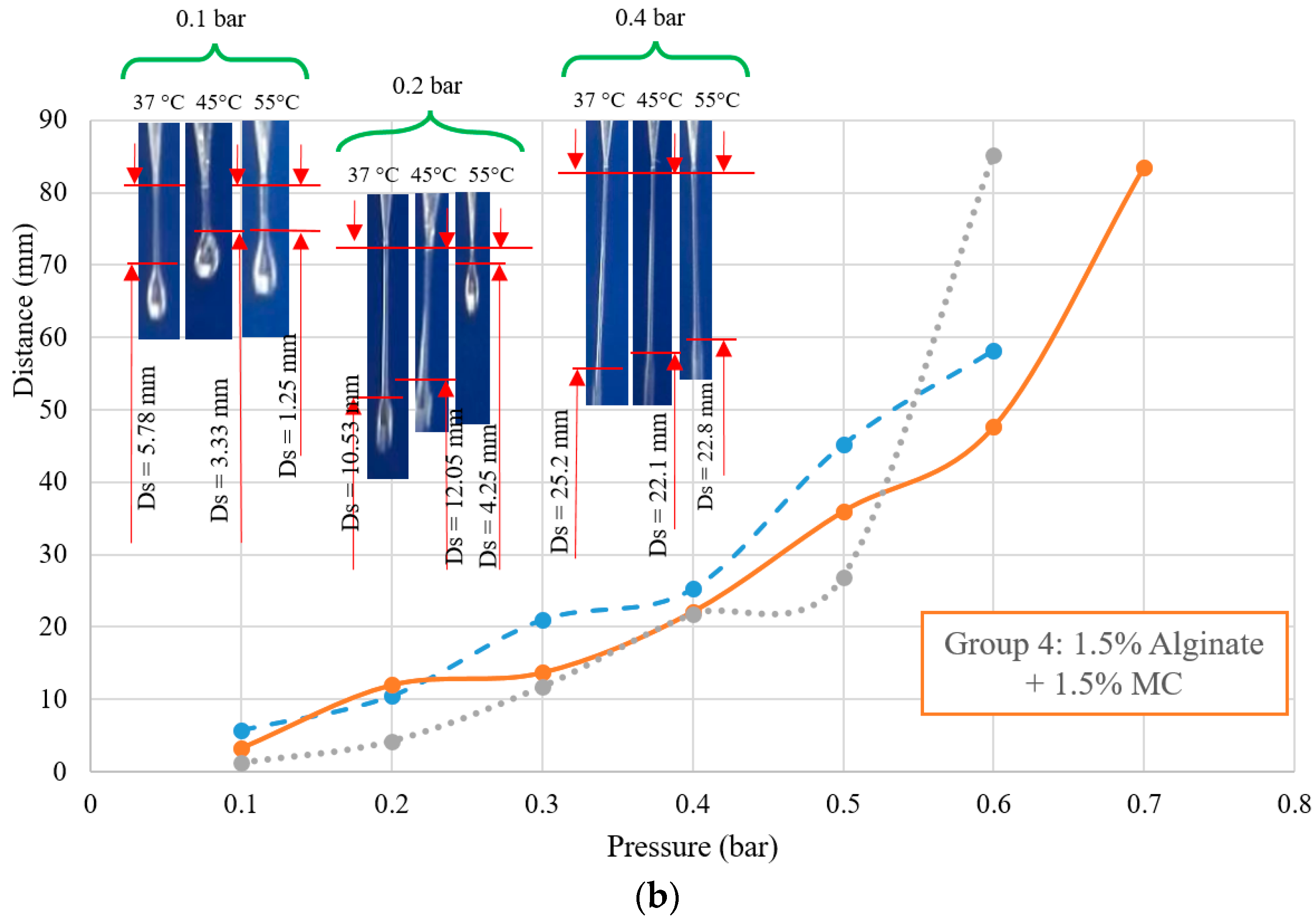
Air pressure is one of the most critical factors affecting printability [2]. Every biomaterial has surface tension and to print a biomaterial, a pressure more than the surface tension of the biomaterials should be applied. Figure 5 shows the effect of printing pressure on purging status of groups 2 and 4 at different temperatures, as an illustration. We defined Ds as the distance between the end of the needle and the position separated by the droplet of biomaterial. As such, for different biomaterials, Ds can be measured and to this end, suitable pressure and temperature can be selected. As shown, for some groups, even at 0.3 bar, the biomaterial was not printable and it was like a droplet hanging from the needle. On the other hand, higher pressures caused instability of extruded biomaterial, and subsequently, poor printability. Group 1 behaved like a highly viscous biomaterial and was not printable at 37 (0.2 bar). At higher pressures, Ds was between 4.8 to 25.8 mm and higher pressures showed higher Ds. Group 3 showed a non-viscous behavior and even at 0.2 bar pressure, Ds of more than 7.5 mm was observed. Our results showed that 0.2 bar was a suitable pressure to dominate the surface tension of biomaterials for groups 1, 2, and 4, while 0.1 bar was found to be more suitable for Group 3.
3.3.2. Nozzle Speed Test
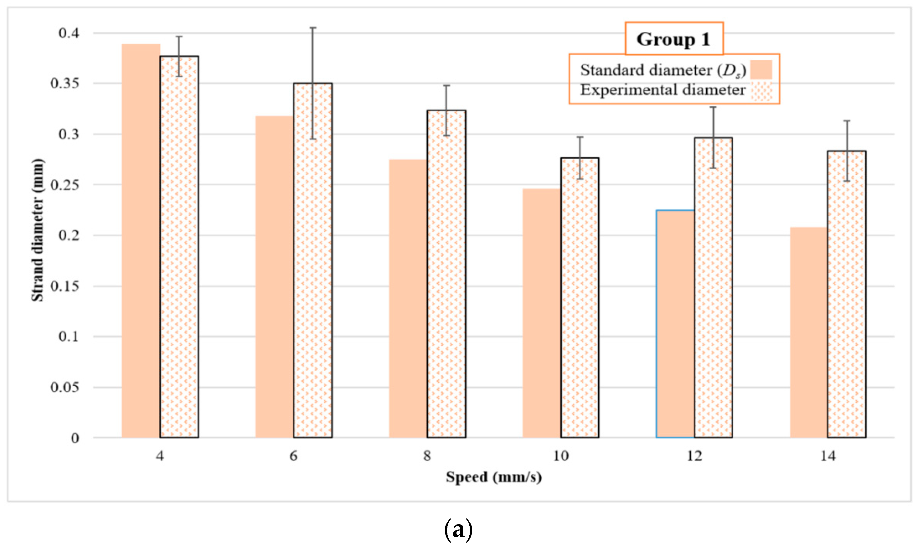
For this set of experiments, nozzle speed was subjected to changes. Firstly, physical crosslinking was used, and groups 2, 3 and 4 were printed on a cold bed (10 °C). However, poor printability was observed for all groups (results not shown here). Hence, chemical crosslinking was implemented using a 50 mM CaCl2. Using Equations (1)–(4), the standard strand diameter was calculated for all groups. Figure 6 shows the results for all groups including experimental and standard strand diameter (inset images are printed scaffolds for group 2 at different nozzle speeds of 6, 14, 18, and 26 mm/s, as an illustration). Results showed that the experimental and theoretical values of strand diameter for Group 1 were similar at a nozzle speed of less than 8 mm/s, while 12 mm/s was observed as a suitable speed for Group 2. For Group 3, the experimental and theoretical values were more similar at higher speeds of more than 30 mm/s while 18 to 24 mm/s were identified as more suitable for Group 4. Overall, in all groups, there was a range of nozzle speeds under which theoretical and experimental values were close, and speeds that fell under or above that range caused poor strand printability. In addition, by increasing the nozzle speed, thinner strand diameters were achieved.
Strand printability and pore printability results are shown in Table 2. Values that were close to 1 ± 0.1 were considered acceptable for both pore and strand printability.
3.3.3. Offset Test
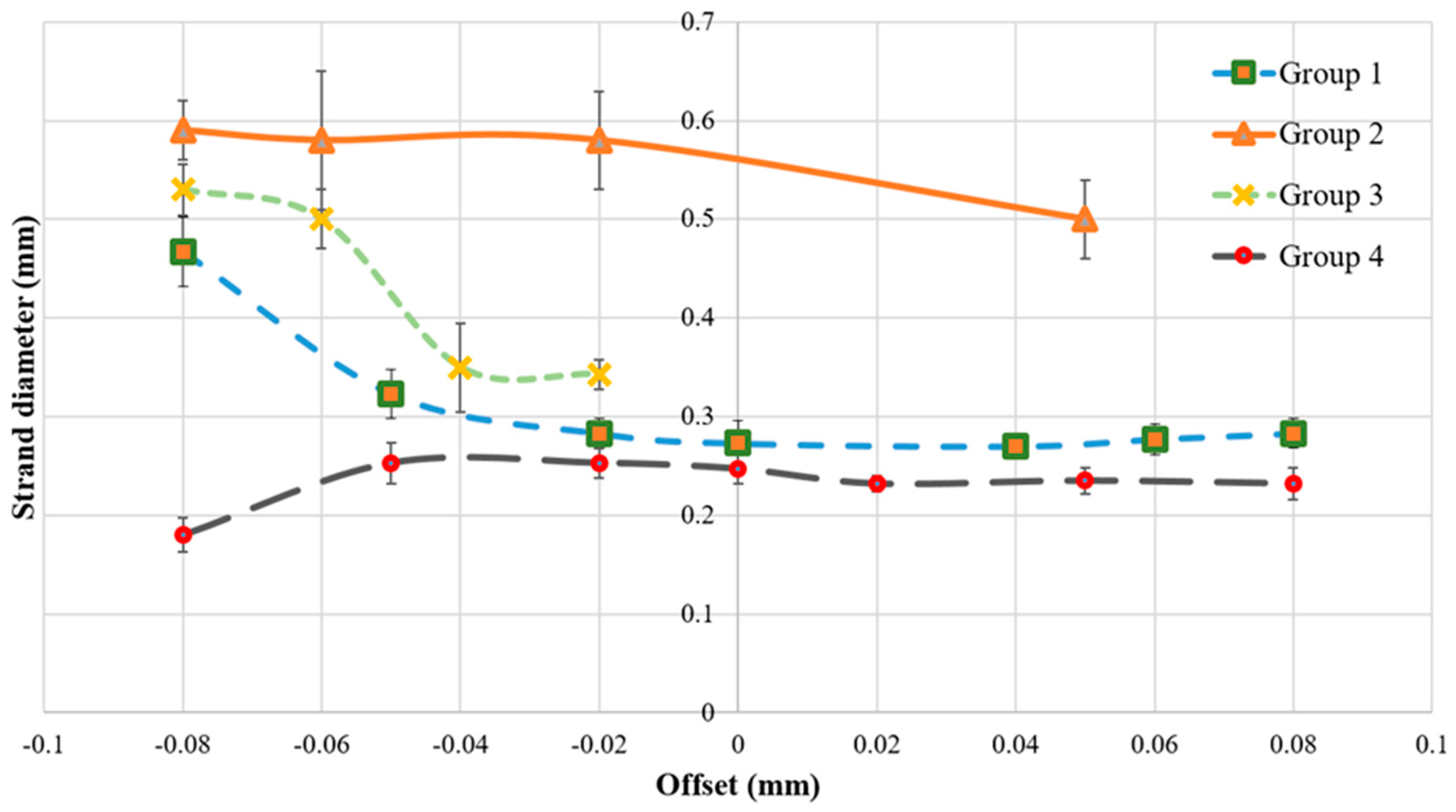
For this section of studies, the offset was modulated to study its influence on printability. Figure 7 shows that offset can significantly affect strand diameter. All groups printed with a 200 µm needle, but with a wide range of strand diameters (between 0.1 to 0.6 mm), were observed as modulating the offset.
3.3.4. Printing Angular Patterns
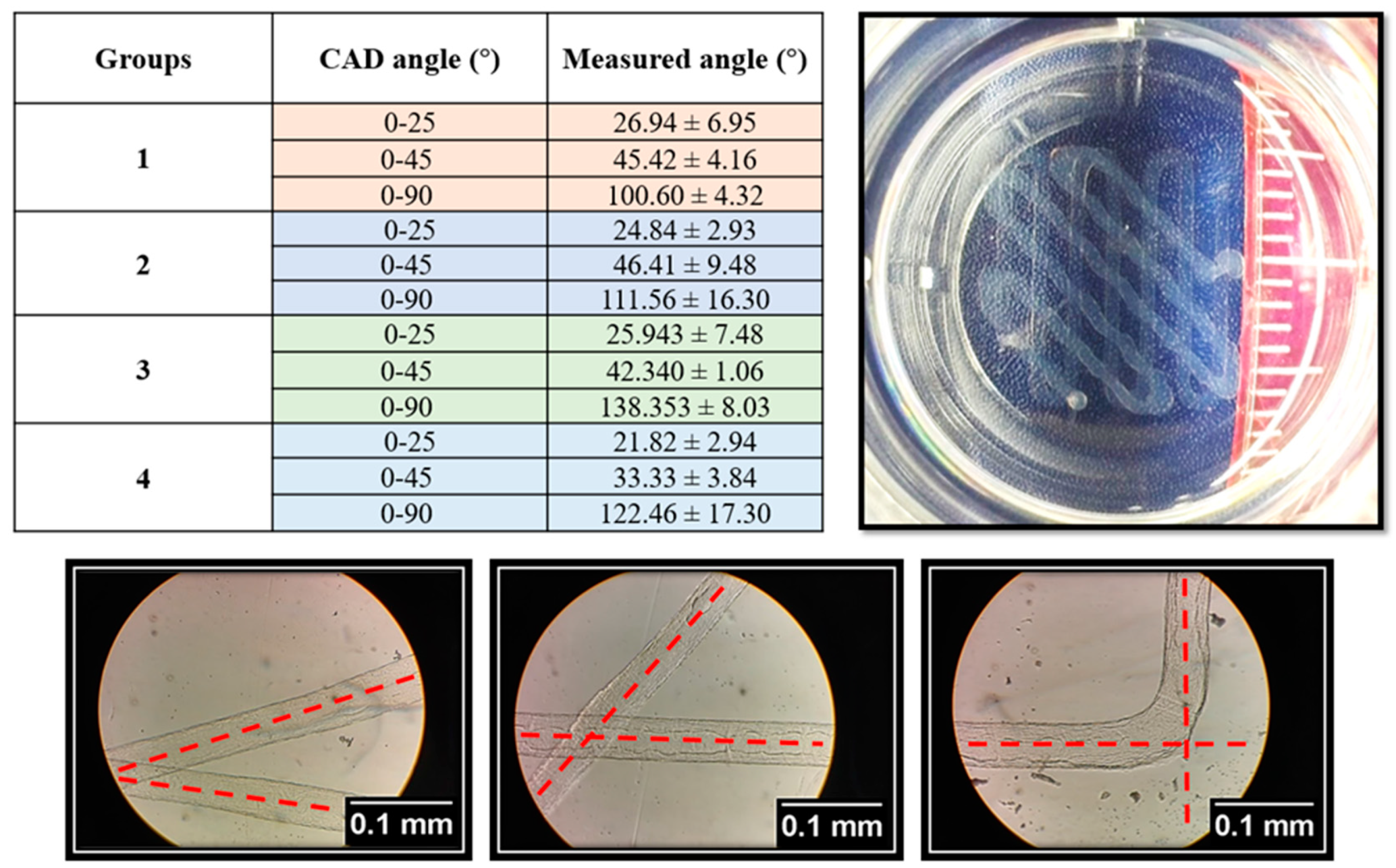
Scaffolds with acute, right, and obtuse angles were printed (Figure 8). Angular pattern printability results showed that not all groups could achieve good angle printability for 25° and 45°. The printing quality became worse at right angles, such that a huge difference was observed in the scaffolds that printed with a 0–90° laydown pattern, as compared to the 0–25° ones.
3.4. Effect of Printing Parameters on 3D Printability
In the proceeding sections, 2D printability was presented. In these sections, 3D printability was discussed in terms of irregularity in the X and Y directions, pore printability, and strand printability for the scaffolds made from different groups of given biomaterials (5, 10, and 15 layers). Table 3 shows the results for irregularity, pore and strand printability, as well as top views of scaffolds with 5, 10, and 15 layers.
4. Discussion
Different methods of scaffold design can be used to manipulate the mechanical properties of hydrogel scaffolds to achieve properties that are best suited for cell support. Various studies have shown that the mechanical properties of scaffolds must be carefully controlled to successfully simulate the extracellular matrix that supports cells in human tissue. This is because there is a dynamic relationship between cell growth and viability and the extracellular matrix [25,31,32,33,34]. These experiments have shown that the water retention rate, elasticity, and degradation rate of a hydrogel construct can, to some extent, be controlled by changing the material composition of the scaffold. In this study, hydrogels containing alginate-gelatin showed a higher water retention capacity than the pure alginate gels. One possible explanation for this observation was that pure alginate molecules experienced stronger intermolecular forces with one another compared to when they were part of hybrid hydrogels. Adding gelatin or MC may interfere with the intermolecular forces between adjacent alginate molecules, and as a result, the attraction between the alginate molecules and surrounding water molecules may be stronger than in pure alginate hydrogels. This leads to greater water absorption. Furthermore, the melting point of gelatin is about 35 °C [35]; therefore, at 37 °C gelatin would be in liquid form, and as a result, there would be gaps in the scaffold which would be replaced by the surrounding water molecules. This result would lead to a higher absorption rate when compared to a pure alginate hydrogel sample. This high water retention capacity allows cells to readily exchange important molecules such as ions and signaling molecules with their environment [25].
Additionally, hybrid hydrogels containing gelatin had a lower elastic modulus compared to alginate-MC hybrid hydrogels, possibly because of the degradation of gelatin at physiological temperatures. The decomposition of gelatin due to its melting point of around 35 °C would cause the formation of gaps in the construct, and this could compromise its mechanical stability and result in a lower elastic modulus. These results indicated that hydrogels could be constructed with different materials depending on the degree of stiffness necessary for the tissue type that requires regeneration. This outcome allows for better specificity and control in scaffold design and construction. Notably, in future studies, water syneresis can be evaluated to consider the effect of shrinkage.
Group 3 showed the highest percentage of degradation in comparison to the other hydrogels. MC is soluble in water at temperatures lower than 40–50 °C, as mentioned earlier, and it has a melting point of about 35 °C [35,36]. The weakened intermolecular interactions of MC and gelatin at physiological temperatures would, therefore, lead to a high rate of degradation of this gel over time. Here, we proposed some compositions with various mechanical and swelling/degradation rates.
Our results also showed different flow behaviors from Newtonian to non-Newtonian ones. Group 1, having the highest viscosity, showed good printability discussed later on. It meant that the more viscous the biomaterial, the more appropriate printability could be achieved. However, high viscous biomaterials may not printable. Referring back to the mentioned general rule, we recommend an appropriate range of viscosity from 300 to 30,000 cps (0.3–30 PaS). Group 4 was not in the recommended range, which agreed with our printability results so that a poor printability was observed for this group. Notably, as we use lower viscous biomaterials; likewise, higher speeds should be implemented. However, it may cause difficulties in printing, such as sudden direction changes in the edges of scaffolds.
From the air pressure perspective, Group 1 behaved like a highly viscous biomaterial. However, it is recommended to mix alginate with other biomaterials to achieve synergistic properties. However, adding gelatin or MC to alginate reduced the viscosity of the final solutions, as discussed previously on the variation of viscosity observed in different groups. Therefore, compared to Group 1, for other groups, a lower amount of pressure is required to dominate the surface tension of biomaterials. Studying the effect of pressure on Ds can clarify an appropriate range of pressure that is suitable for printing. Owing to several groups with different viscosities, pressures between 0.1 to 0.2 showed good results, and at either lower or higher pressures, the biomaterials were not printable or had an unstable printing condition due to the application of high pressure. Referring to the changes in viscosity among the different groups, the lower viscous groups were printable at relatively higher nozzle speeds. It meant that due to their relatively lower viscosities (e.g., Groups 3 and 4), the biomaterials flowed easily and at the same pressure required to increase the nozzle speed to prevent extra deposition of biomaterials. As mentioned earlier, Group 1 was printable at speeds around 10 mm/s while the starting point of speed for groups 3 and 4 was more than 18 mm/s (Figure 6).
From a 2D strand and pore printability point of view, Group 1 had acceptable strand printability for speeds ranging from 4 to 8 mm/s, whereas pore printability showed acceptable results for speeds between 4 and 14 mm/s. However, Group 2 did not have acceptable strand printability for speeds less than 8 mm/s. This result might be due to a lower viscosity compared to Group 1, and so higher speeds were required to reach acceptable printability. In addition, speeds higher than 14 mm/s showed poor strand printability for Group 2 whereas, for all speeds in between 6 and 22 mm/s, the pore printability was acceptable. It meant that using some speeds; we may achieve acceptable pore printability while strand printability may not be acceptable. Hence, both pore and strand printability should be considered together to find a suitable nozzle printing speed rather than considering either pore or strand printability separately. It should be noted that the criteria used only accounted for pore shape. In this case, it meant that for the cited parameters, the scaffolds still presented perfectly square pores but with different sizes from the design. For Group 3, speeds more than 30 mm/s showed an appropriate range of pore and strand printability. For the last group, all speeds between 18 and 24 mm/s showed acceptable printability.
Using an offset of −0.02 to 0.08 mm, we observed strand diameter between 200 and 300 µm for groups 1 and 4. At the offset less than −0.02 mm, a significant change in strand diameter was observed. For Group 3, strand diameters of more than 300 µm were observed and this may have been due to having low viscosity resulting in quick biomaterial flow leading to a relatively large strand diameter. Group 4 showed a decrease in strand diameter by increasing the offset. The offset should be selected carefully because having a large space between the printing bed and needle leads to non-continuous printing. Meanwhile, having a small offset may lead to squeezing of the biomaterial and prevention of the proper flow of biomaterial during the deposition.
Regarding angle printing, at acute angles, angle printability was acceptable while, for example, at 90, poor printability was observed in terms of angle. These results were interpreted as meaning that changing the needle direction by having a sharp angle of more than 90 may lead to poor angle printability due to a sudden change of the direction of the nozzle. Such a change in direction may cause stretching of the strands and results in modulating the strand diameter.
In agreement with the 2D printability results, 3D printability studies showed that all printed scaffolds had acceptable pore printability while strand printability was not acceptable (most values were more than 1 ± 0.1). As mentioned, the criteria used only accounted for pore shape. Hence, both pore and strand printability should be considered. Surprisingly, strand printability has been neglected in the literature and our results showed that while having acceptable pore printability, scaffolds can also have poor strand printability. One possible solution to address poor strand printability is to modulate the nozzle speed at constant pressures to get closer to the theoretical values. However, using such an approach, other interrelated factors, such as poor printability, can be affected. Except for Group 4, all the groups showed less than 10 percent irregularity in the X and Y directions. For Groups 1 and 2, scaffolds with 15 layers were printed but Groups 3 and 4 showed poor printability for scaffolds made from more than five layers. Referring back to Section 3.2, Groups 3 and 4 with relatively lower viscosities showed poor printability while other groups showed better printability. The viscosity of biomaterials can significantly influence the printability of the bioplotted scaffolds, such that high viscosity biomaterials need higher pressure and low viscous materials require less pressure to be extruded.
Overall, many factors are causing a deviancy between experimental and theoretical values, including pressure, nozzle speed, and offset. These are interrelated elements from a printability perspective and, thus, modulating one of them can affect the other elements. That said, all elements should be selected carefully to avoid, on the one hand, any strand coiling owing to over-extrusion of an extruded strand, and on the other hand, using a low pressure that cannot dominate the surface tension of the biomaterial. To create a clear picture of printability and significantly effective elements, we developed the following linear regression models (R2 more than 85%) to map the relationship between the studied parameters including nozzle speed, pore, and strand printability for 2D printing (Table 4), based on the results presented in Table 2.
It is worthwhile to cite the fact that a high concentration of alginate is not an appropriate environment for cells [37]. High concentrations of alginate can interrupt diffusion mass transfer mechanisms and lead to low cell viability. Inhabitation of cell migration/proliferation is another reason to avoid high concentration alginate. That being said, the present study showed that we could mix other cell-friendly hydrogels such as gelatin to have a low concentration of alginate along with improving the printability of such low concentration alginate.
It should be noted that this study investigated factors that affected printability. However, it should be noted that cell viability is a vital factor to be considered alongside other mentioned factors. It means that factors affecting printability such as pressure can directly affect cell viability and that is why it is important to consider cell viability. Readers are encouraged to check a recent study on printability and cell viability for more information [29].
5. Conclusions
Hydrogels are valuable concerning their ability to serve as an appropriate environment for cells due to their ease of preparation and similarity to the extracellular matrix of many human tissues. The extrusion-based bioprinting method is used widely to create hydrogel scaffolds for different tissue engineering applications. In this regard, it is recommended to mix hydrogels to achieve synergistic properties. Here, we examined the swelling, as well as degradation, rate, and mechanical properties (elastic moduli) of hydrogels with various compositions of alginate, gelatin, and MC. The results showed that composite hydrogels had better water absorption ability compared to a pure alginate hydrogel. Additionally, all combinations of hydrogels showed a decreasing pattern of elastic modulus with time, while alginate-MC combination gels showed the highest elastic moduli. After evaluating scaffolds from the mechanical perspective, more experiments were conducted to investigate the hydrogel printability. The results showed that biomaterial-related elements, e.g., viscosity, and fabrication-related ones, e.g., air pressure, nozzle speed, offset, and selected angular pattern, could influence the printing quality. Modulating these parameters, we improved the printability of different groups of hydrogels, including alginate, gelatin, and MC. Conducting research studies on printability can open the door for further improvements in the fabrication of hydrogel scaffolds using the extrusion-based technique. To conclude, taking biomaterial- and fabrication-related elements, printability can be improved and accordingly, scaffolds can be specialized depending on which tissue requires regenerative tissue therapy.
Author Contributions
Conceptualization, S.N. and X.C.; Methodology, S.N., M.S., Z.B; Software, S.N.; Validation, S.N., N.K.S. and Z.B.; Formal Analysis, S.N., N.K.S., Z.B.; Investigation, S.N., Z.B.; Resources, X.C.; Data Curation, S.N.; Writing-Original Draft Preparation, S.N.; Writing-Review & Editing, S.N., X.C.; Visualization, S.N., M.S., and N.K.S.; Supervision, X.C.; Project Administration, S.N.; Funding Acquisition, X.C. All authors have read and agreed to the published version of the manuscript.
Funding
This study was funded by the Natural Sciences and Engineering Research Council of Canada (NSERC, grant number RGPIN-2014-05648). Furthermore, we thank Eva Karki for assistance with the degradation test.
Conflicts of Interest
The authors declare no conflict of interest.
References
- Naghieh, S.; Sarker, M.; Izadifar, M.; Chen, X. Dispensing-based bioprinting of mechanically-functional hybrid scaffolds with vessel-like channels for tissue engineering applications—A brief review. J. Mech. Behav. Biomed. Mater. 2018, 78, 298–314. [Google Scholar] [CrossRef] [PubMed]
- He, Y.; Yang, F.; Zhao, H.; Gao, Q.; Xia, B.; Fu, J. Research on the printability of hydrogels in 3D bioprinting. Sci. Rep. 2016, 6, 29977. [Google Scholar] [CrossRef] [PubMed]
- Naghieh, S.; Karamooz-Ravari, M.R.; Sarker, M.; Karki, E.; Chen, X. Influence of crosslinking on the mechanical behavior of 3D printed alginate scaffolds: Experimental and numerical approaches. J. Mech. Behav. Biomed. Mater. 2018, 80, 111–118. [Google Scholar] [CrossRef] [PubMed] [Green Version]
- Skardal, A.; Atala, A. Biomaterials for integration with 3-D bioprinting. Ann. Biomed. Eng. 2015, 43, 730–746. [Google Scholar] [CrossRef] [PubMed]
- Ding, H.; Chang, R.C. Printability Study of Bioprinted Tubular Structures Using Liquid Hydrogel Precursors in a Support Bath. Appl. Sci. 2018, 8, 403. [Google Scholar] [CrossRef] [Green Version]
- Wen, J.H.; Vincent, L.G.; Fuhrmann, A.; Choi, Y.S.; Hribar, K.C.; Taylor-Weiner, H.; Chen, S.; Engler, A.J. Interplay of matrix stiffness and protein tethering in stem cell differentiation. Nat. Mater. 2014, 13, 979–987. [Google Scholar] [CrossRef] [Green Version]
- Chung, J.H.Y.; Naficy, S.; Yue, Z.; Kapsa, R.; Quigley, A.; Moulton, S.E.; Wallace, G.G. Bio-ink properties and printability for extrusion printing living cells. Biomater. Sci. 2013, 1, 763–773. [Google Scholar] [CrossRef] [Green Version]
- Ouyang, L.; Yao, R.; Zhao, Y.; Sun, W. Effect of bioink properties on printability and cell viability for 3D bioplotting of embryonic stem cells. Biofabrication 2016, 8, 035020. [Google Scholar] [CrossRef]
- Bertassoni, L.E.; Cardoso, J.C.; Manoharan, V.; Cristino, A.L.; Bhise, N.S.; Araujo, W.A.; Zorlutuna, P.; Vrana, N.E.; Ghaemmaghami, A.M.; Dokmeci, M.R.; et al. Direct-write Bioprinting of Cell-laden Methacrylated Gelatin Hydrogels. Biofabrication 2014, 6, 024105. [Google Scholar] [CrossRef] [Green Version]
- Sarker, M.; Izadifar, M.; Schreyer, D.; Chen, X. Influence of ionic crosslinkers (Ca2+/Ba2+/Zn2+) on the mechanical and biological properties of 3D Bioplotted Hydrogel Scaffolds. J. Biomater. Sci. Polym. Ed. 2018, 29, 1126–1154. [Google Scholar] [CrossRef]
- Sarker, M.D.; Naghieh, S.; McInnes, A.D.; Ning, L.; Schreyer, D.; Chen, X. Bio-fabrication of peptide-modified alginate scaffolds: Printability, mechanical stability and neurite outgrowth assessments. Bioprinting 2019, 14, e00045. [Google Scholar] [CrossRef]
- You, F.; Wu, X.; Chen, X. 3D Printing of Porous Alginate/gelatin Hydrogel Scaffolds and Their Mechanical Property Characterization. Int. J. Polym. Mater. Polym. Biomater. 2016, 66, 299–306. [Google Scholar] [CrossRef]
- Murphy, S.V.; Atala, A. 3D bioprinting of tissues and organs. Nat. Biotechnol. 2014, 32, 773–785. [Google Scholar] [CrossRef] [PubMed]
- Göhl, J.; Markstedt, K.; Mark, A.; Håkansson, K.; Gatenholm, P.; Edelvik, F. Simulations of 3D bioprinting: Predicting bioprintability of nanofibrillar inks. Biofabrication 2018, 10, 34105. [Google Scholar] [CrossRef]
- Kyle, S.; Kyle, S.; Jessop, Z.M.; Al-sabah, A.; Whitaker, I.S. ‘Printability’ of Candidate Biomaterials for Extrusion Based 3D Printing: State-of-the-Art. Adv. Healthc. Mater. 2017, 6, 1700264. [Google Scholar] [CrossRef]
- Müller, M.; Öztürk, E.; Arlov, Ø.; Gatenholm, P.; Zenobi-Wong, M. Alginate Sulfate-Nanocellulose Bioinks for Cartilage Bioprinting Applications. Ann. Biomed. Eng. 2016, 45, 1–14. [Google Scholar] [CrossRef]
- Gandhi, J.K.; Opara, E.C.; Brey, E.M. Alginate-based strategies for therapeutic vascularization. Ther. Deliv. 2013, 4, 327–341. [Google Scholar] [CrossRef]
- Freeman, F.E.; Kelly, D.J. Tuning Alginate Bioink Stiffness and Composition for Controlled Growth Factor Delivery and to Spatially Direct MSC Fate within Bioprinted Tissues. Sci. Rep. 2017, 7, 1–12. [Google Scholar] [CrossRef] [Green Version]
- Ivanovska, J.; Zehnder, T.; Lennert, P.; Sarker, B.; Boccaccini, A.R.; Hartmann, A.; Schneider-Stock, R.; Detsch, R. Biofabrication of 3D Alginate-Based Hydrogel for Cancer Research: Comparison of Cell Spreading, Viability, and Adhesion Characteristics of Colorectal HCT116 Tumor Cells. Tissue Eng. Part C Methods 2016, 22, 708–715. [Google Scholar] [CrossRef]
- Bohari, S.P.M.; Hukins, D.W.L.; Grover, L.M. Effect of calcium alginate concentration on viability and proliferation of encapsulated fibroblasts. Biomed. Mater. Eng. 2011, 21, 159–170. [Google Scholar] [CrossRef]
- Luo, Y.; Luo, G.; Gelinsky, M.; Huang, P.; Ruan, C. 3D bioprinting scaffold using alginate/polyvinyl alcohol bioinks. Mater. Lett. 2017, 189, 295–298. [Google Scholar] [CrossRef]
- Ning, L.; Xu, Y.; Chen, X.; Schreyer, D.J. Influence of mechanical properties of alginate-based substrates on the performance of Schwann cells in culture. J. Biomater. Sci. Polym. Ed. 2016, 27, 898–915. [Google Scholar] [CrossRef] [PubMed]
- Markstedt, K.; Mantas, A.; Tournier, I.; Ávila, H.M.; Hägg, D.; Gatenholm, P. 3D Bioprinting Human Chondrocytes with Nanocellulose Alginate Bioink for Cartilage Tissue Engineering Applications. Biomacromolecules 2015, 16, 1489–1496. [Google Scholar] [CrossRef] [PubMed]
- Habib, A.; Sathish, V.; Mallik, S.; Khoda, B. 3D printability of alginate-carboxymethyl cellulose hydrogel. Materials. 2018, 11, 454. [Google Scholar] [CrossRef] [Green Version]
- Ivanov, C.; Popa, M.; Ivanov, M.; Popa, A.A. Synthesis of poly (vinyl alcohol)-methyl cellulose hydrogel as possible scaffolds in tissue engineering. J. Optoelectron. Adv. Mater. 2007, 9, 3440–3444. [Google Scholar]
- Pan, T.; Song, W.; Cao, X.; Wang, Y. 3D bioplotting of gelatin/alginate scaffolds for tissue engineering: Influence of crosslinking degree and pore architecture on physicochemical properties. J. Mater. Sci. Technol. 2016, 32, 889–900. [Google Scholar] [CrossRef]
- Gao, T.; Gillispie, G.J.; Copus, J.S.; PR, A.K.; Seol, Y.-J.; Atala, A.; Yoo, J.J.; Lee, S.J. Optimization of gelatin-alginate composite bioink printability using rheological parameters: A systematic approach. Biofabrication 2018, 10, 034106. [Google Scholar] [CrossRef]
- Lee, S.-H.; Lee, J.H.; Cho, Y.-S. Analysis of degradation rate for dimensionless surface area of well-interconnected PCL scaffold via in-vitro accelerated degradation experiment. Tissue Eng. Regen. Med. 2014, 11, 446–452. [Google Scholar] [CrossRef]
- Naghieh, S.; Sarker, M.D.; Abelseth, E.; Chen, X. Indirect 3D bioprinting and characterization of alginate scaffolds for potential nerve tissue engineering applications. J. Mech. Behav. Biomed. Mater. 2019, 93, 183–193. [Google Scholar] [CrossRef] [Green Version]
- Huang, T.; Fan, C.; Zhu, M.; Zhu, Y.; Zhang, W.; Li, L. 3D-printed scaffolds of biomineralized hydroxyapatite nanocomposite on silk fibroin for improving bone regeneration. Appl. Surf. Sci. 2019, 467, 345–353. [Google Scholar] [CrossRef]
- Singhvi, R.; Kumar, A. Engineering cell shape and function. Science 1994, 264, 696–698. [Google Scholar] [CrossRef] [PubMed] [Green Version]
- Chen, C.S.; Mrksich, M.; Huang, S.; Whitesides, G.M.; Ingber, D.E. Geometric Control of Cell Life and Death. Science 1997, 276, 1425–1428. [Google Scholar] [CrossRef] [PubMed] [Green Version]
- Nanda, S.; Sood, N.; Reddy, B.V.K.; Markandeywar, T.S. Preparation and Characterization of Poly ( vinyl alcohol)-chondroitin Sulphate Hydrogel as Scaffolds for Articular Cartilage Regeneration. Indian J. Mater. Sci. 2013, 2013, 01636236564. [Google Scholar] [CrossRef] [Green Version]
- Tibbitt, M.W.; Anseth, K.S. Hydrogels as extracellular matrix mimics for 3D cell culture. Biotechnol. Bioeng. 2009, 103, 655–663. [Google Scholar] [CrossRef] [Green Version]
- Shariff, S.; Kaler, A.K. Principles & Interpretation of Laboratory Practices in Surgical Pathology; JP Medical Ltd.: Bhotahity, Kathmandu, Nepal, 2016. [Google Scholar]
- Ruel-Gariepy, E.; Leroux, J.-C. In situ-forming hydrogels—Review of temperature-sensitive systems. Eur. J. Pharm. Biopharm. 2004, 58, 409–426. [Google Scholar] [CrossRef]
- Matyash, M.; Despang, F.; Mandal, R.; Fiore, D.; Gelinsky, M.; Ikonomidou, C. Novel Soft Alginate Hydrogel Strongly Supports Neurite Growth and Protects Neurons Against Oxidative Stress. Tissue Eng. Part A 2012, 18, 55–66. [Google Scholar] [CrossRef]
Figure 1.
The schematic diagram of an extrusion-based 3D bio-printer.

Figure 2.
The rate of absorption of the samples composed of various biomaterials is indicated by the change in mass of the samples over time.
Figure 2.
The rate of absorption of the samples composed of various biomaterials is indicated by the change in mass of the samples over time.

Figure 3.
The compressive strength of the scaffolds of varying composition over time is shown here. Statistical significance was calculated using a Student’s t-test (* was, and ** were used to represent p < 0.05 and p < 0.01, respectively).
Figure 3.
The compressive strength of the scaffolds of varying composition over time is shown here. Statistical significance was calculated using a Student’s t-test (* was, and ** were used to represent p < 0.05 and p < 0.01, respectively).

Figure 4.
Shear stress as a function of the Shear rate for each solution.

Figure 5.
Effect of printing pressure on Ds for (a) group 2; (b) and group 4, as an illustration.


Figure 6.
Effect of nozzle speed on the printability of Groups 1 to 3 (pressure: 0.2 bar) and 4 (pressure: 0.1 bar): comparison between Ds and experimental strand diameter (inset images are printed scaffolds for Group 2 at different nozzle speeds of 6, 14, 18, and 26 mm/s, as an illustration). (a) group 1; (b) group 2; (c) group 3; and (d) group 4.


Figure 7.
Effect of offset on the strand diameter of scaffolds made of Groups 1 to 4.

Figure 8.
Effect of the angular pattern on the printability of scaffolds with acute, right, and obtuse angles.
Figure 8.
Effect of the angular pattern on the printability of scaffolds with acute, right, and obtuse angles.


Table 1.
Viscosity behavior for different groups.
| Groups | Min Viscosity (PaS) | Max Viscosity (PaS) |
|---|---|---|
| 1 | 2.25 ± 0.04 | 6.58 ± 0.06 |
| 2 | 0.78 ± 0.06 | 1.38 ± 0.07 |
| 3 | 0.48 ± 0.004 | 0.84 ± 0.07 |
| 4 | 0.21 ± 0.01 | 0.47 ± 0.03 |
Table 2.
Effect of nozzle speed on strand and pore printability.
| Groups | Pressure (bar) | Speed | Strand Printability | Pore Printability |
|---|---|---|---|---|
| 1 | 0.2 | 4 | 0.97 ± 0.060 | 1.01 ± 0.002 |
| 0.2 | 6 | 1.10 ± 0.180 | 1.01 ± 0.012 | |
| 0.2 | 8 | 1.18 ± 0.090 | 1.01 ± 0.009 | |
| 0.2 | 10 | 1.12 ± 0.140 | 1.01 ± 0.003 | |
| 0.2 | 12 | 1.32 ± 0.150 | 1.00 ± 0.003 | |
| 0.2 | 14 | 1.36 ± 0.150 | 0.98 ± 0.022 | |
| 2 | 0.2 | 6 | 0.81 ± 0.066 | 1.139 ± 0.086 |
| 0.2 | 8 | 0.89 ± 0.069 | 1.050 ± 0.042 | |
| 0.2 | 10 | 0.91 ± 0.083 | 1.066 ± 0.070 | |
| 0.2 | 12 | 0.95 ± 0.062 | 1.010 ± 0.006 | |
| 0.2 | 14 | 1.09 ± 0.049 | 1.048 ± 0.054 | |
| 0.2 | 18 | 1.22 ± 0.077 | 1.002 ± 0.015 | |
| 0.2 | 22 | 1.26 ± 0.111 | 1.04 ± 0.027 | |
| 3 | 0.1 | 20 | 1.203 ± 0.136 | 1.152 ± 0.135 |
| 0.1 | 30 | 0.997 ± 0.067 | 1.012 ± 0.019 | |
| 0.1 | 35 | 0.871 ± 0.059 | 1.010 ± 0.010 | |
| 0.1 | 40 | 0.897 ± 0.106 | 1.010 ± 0.018 | |
| 0.1 | 45 | 0.925 ± 0.056 | 1.045 ± 0.065 | |
| 0.1 | 50 | 0.975 ± 0.059 | 1.033 ± 0.041 | |
| 0.1 | 55 | 0.923 ± 0.052 | 0.937 ± 0.122 | |
| 4 | 0.2 | 18 | 1.075 ± 0.110 | 1.338 ± 0.488 |
| 0.2 | 20 | 0.931 ± 0.138 | 0.974 ± 0.036 | |
| 0.2 | 22 | 0.939 ± 0.097 | 0.982 ± 0.056 | |
| 0.2 | 24 | 0.947 ± 0.116 | 1.039 ± 0.029 |
Table 3.
The 3D printability results for the bioplotted scaffolds made from Groups 1 to 4. ✕ shows that biomaterials are not printable or a large deviation is observed.
Table 3.
The 3D printability results for the bioplotted scaffolds made from Groups 1 to 4. ✕ shows that biomaterials are not printable or a large deviation is observed.
| Groups | Printed Layers | Irregularity X | Irregularity Y | Pore Printability | Strand Printability | Printed Scaffold (Top View) |
|---|---|---|---|---|---|---|
| 1 | 5 | 0.08 | 0.05 | 0.96 ± 0.02 | 1.29 ± 0.07 |  |
| 10 | 0.05 | 0.06 | 1.00 ± 0.04 | 1.71 ± 0.07 |  | |
| 15 | 0.10 | 0.07 | 1.00 ± 0.01 | 1.64 ± 0.09 |  | |
| 2 | 5 | 0.07 | 0.03 | 0.97 ± 0.02 | 1.22 ± 0.02 |  |
| 10 | 0.09 | 0.03 | 1.01 ± 0.01 | 1.92 ± 0.27 |  | |
| 15 | 0.09 | 0.08 | 0.97 ± 0.02 | 1.70 ± 0.25 |  | |
| 3 | 5 | 0.07 | 0.03 | 1.02 ± 0.07 | ✕ |  |
| 10 | ✕ | ✕ | ✕ | ✕ |  | |
| 4 | 5 | 0.11 | 0.06 | 1.05 ± 0.45 | 1.10 ± 0.34 |  |
| 10 | 0.08 | 0.07 | 0.97 ± 0.05 | 1.01 ± 0.11 |  | |
| 15 | ✕ | ✕ | ✕ | ✕ |  |
Table 4.
Linear regression models created based on the experimental results reported in Table 2.
Table 4.
Linear regression models created based on the experimental results reported in Table 2.
| Groups | Applied Pressure (bar) | Linear Regression Models (Nozzle Speed: Ns, Pore Printability: P, Strand Printability: S) |
|---|---|---|
| 1 | 0.2 | S = 51.5 − 3.39 Ns − 50.1 P + 3.38 Ns × P |
| 2 | 0.2 | S = 0.08 + 0.108 Ns + 0.53 P − 0.075 Ns × P |
| 3 | 0.1 | S = −2.06 + 0.0528 Ns + 2.96 P − 0.0525 Ns × P |
| 4 | 0.2 | S = −0.6298 + 0.06394 Ns + 1.534 P − 0.06222 Ns × P |
© 2019 by the authors. Licensee MDPI, Basel, Switzerland. This article is an open access article distributed under the terms and conditions of the Creative Commons Attribution (CC BY) license (http://creativecommons.org/licenses/by/4.0/).
Share and Cite
MDPI and ACS Style
Naghieh, S.; Sarker, M.; Sharma, N.K.; Barhoumi, Z.; Chen, X. Printability of 3D Printed Hydrogel Scaffolds: Influence of Hydrogel Composition and Printing Parameters. Appl. Sci. 2020, 10, 292. https://doi.org/10.3390/app10010292
AMA Style
Naghieh S, Sarker M, Sharma NK, Barhoumi Z, Chen X. Printability of 3D Printed Hydrogel Scaffolds: Influence of Hydrogel Composition and Printing Parameters. Applied Sciences. 2020; 10(1):292. https://doi.org/10.3390/app10010292
Chicago/Turabian StyleNaghieh, Saman, MD Sarker, N. K. Sharma, Zohra Barhoumi, and Xiongbiao Chen. 2020. "Printability of 3D Printed Hydrogel Scaffolds: Influence of Hydrogel Composition and Printing Parameters" Applied Sciences 10, no. 1: 292. https://doi.org/10.3390/app10010292
Note that from the first issue of 2016, this journal uses article numbers instead of page numbers. See further details here.