Crosslinked Facilitated Transport Membranes Based on Carboxymethylated NFC and Amine-Based Fixed Carriers for Carbon Capture, Utilization, and Storage Applications


 , , and
Abstract
:Featured Application
Abstract
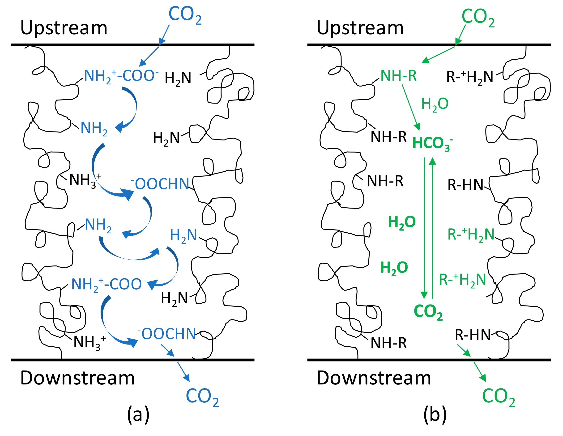
1. Introduction
2. Materials and Methods
2.1. Materials
2.2. Preparation of Carboxymethylated NFC
2.3. Elaboration of Amine-Functionalized cmNFC-Based Crosslinked Membranes
2.4. Kinetics Followed by 29Si NMR Spectroscopy
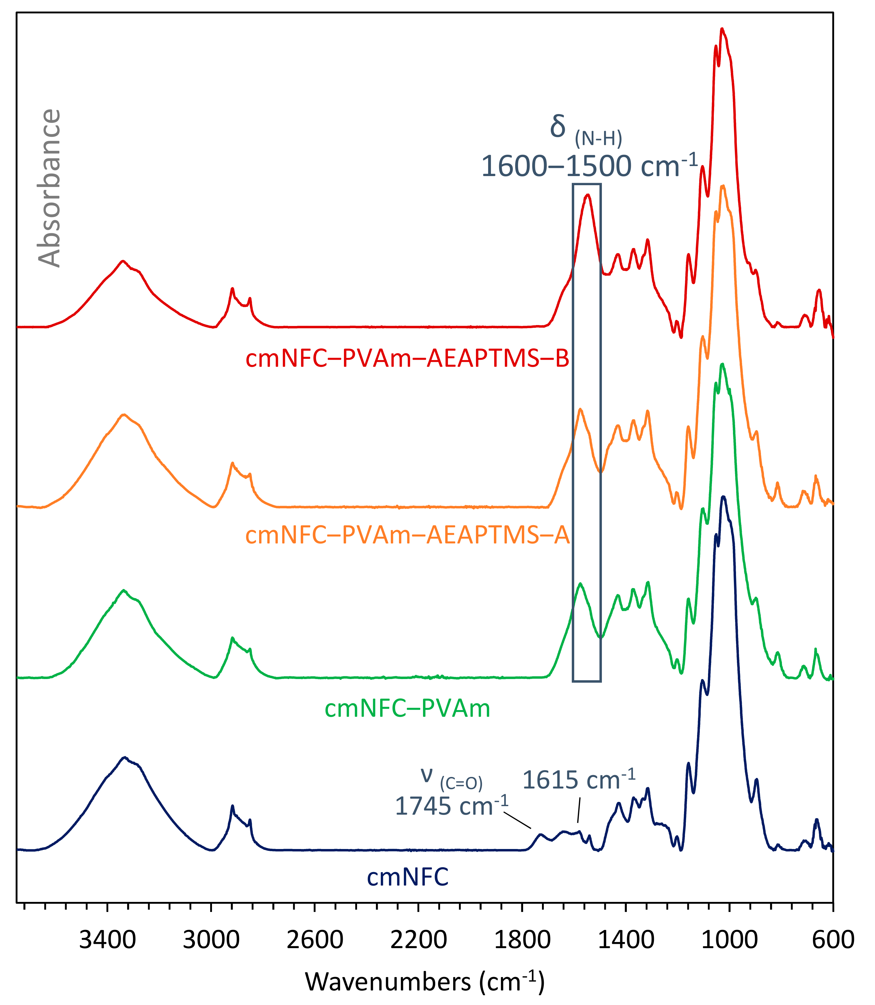
2.5. FTIR Spectroscopy
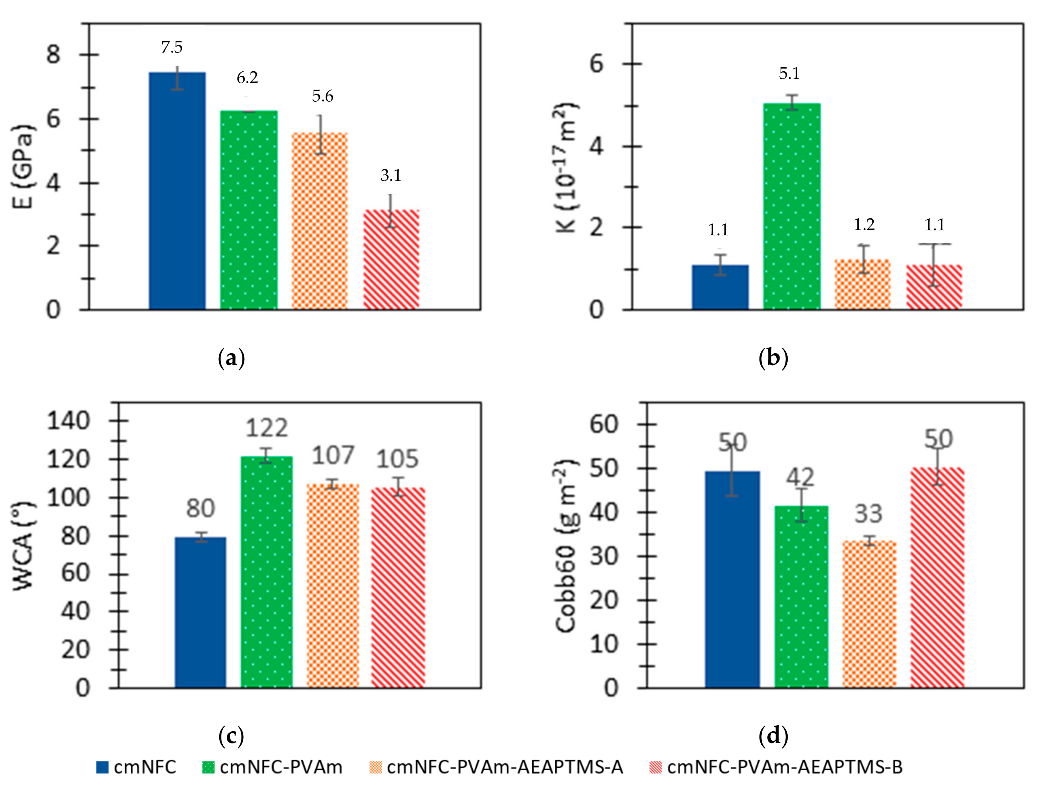
2.6. Tensile Tests
2.7. Intrinsic Air Permeability Measurements
2.8. Water Contact Angle Measurements
2.9. Water Absorption Measurements
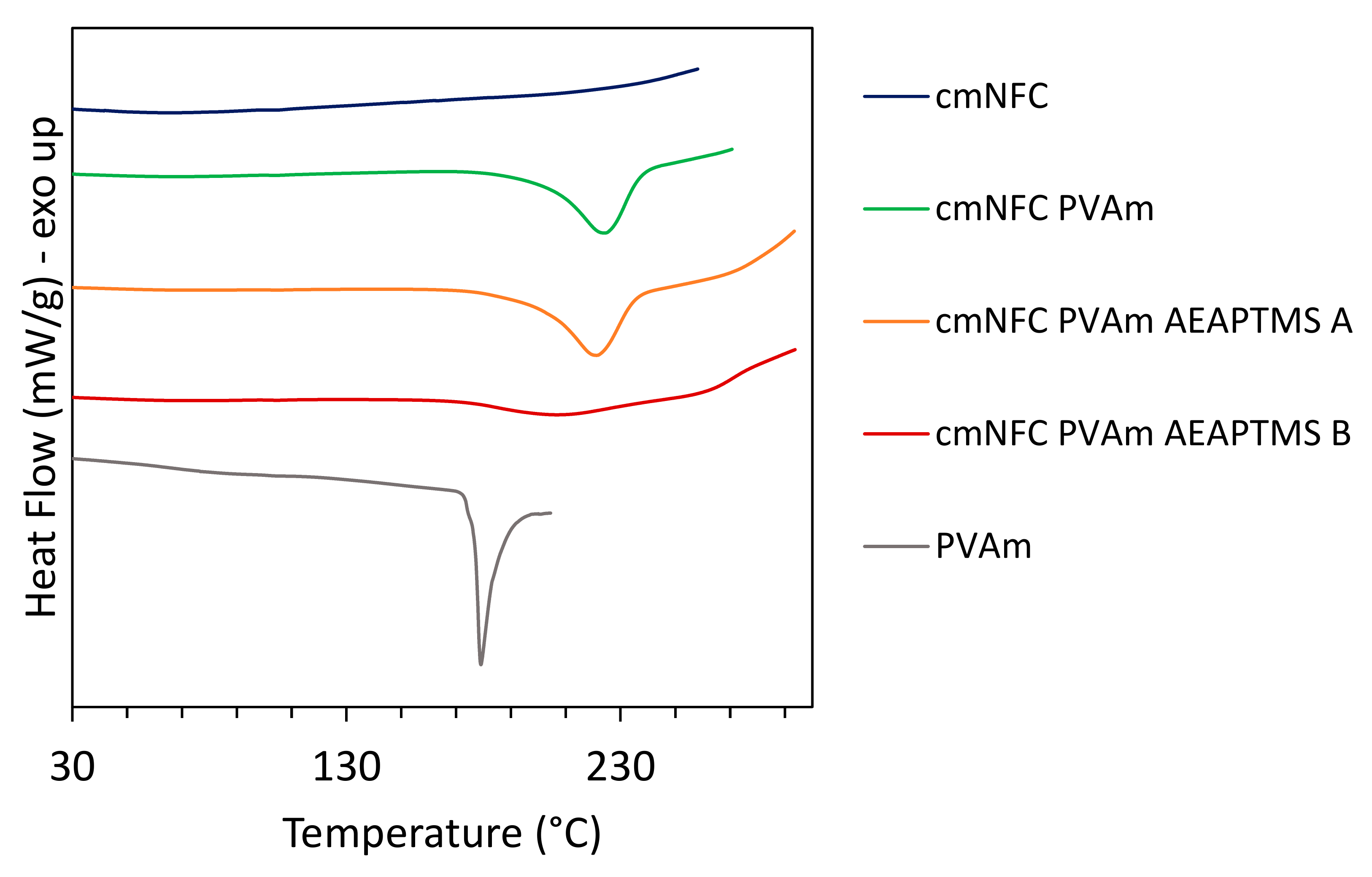
2.10. DSC Analysis
2.11. Field Emission Gun-Scanning Electron Microscopy
2.12. Energy-Dispersive X-ray Spectroscopy
2.13. Elemental Analysis
2.14. Gas Permeability Measurements
3. Results and Discussion
3.1. Membrane Preparation
3.2. Characterizations of the Membranes
3.3. Properties of the Membranes
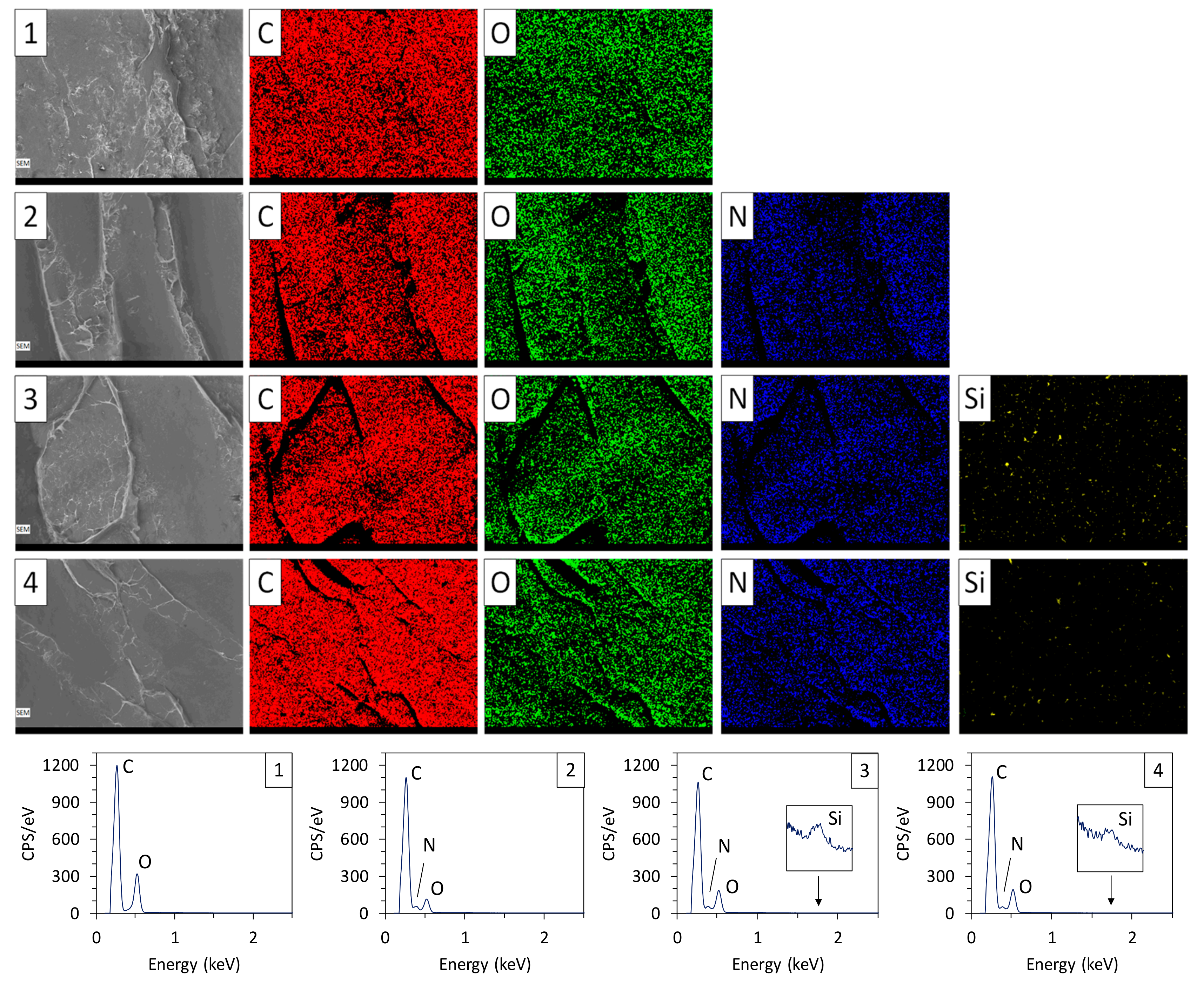
3.4. Morphology of the Membranes and Elemental Quantification
3.5. Separation Performance
4. Conclusions
Author Contributions
Funding
Acknowledgments
Conflicts of Interest
References
- Earth System Research Laboratory Global Monitoring Division. Available online: https://www.esrl.noaa.gov/gmd/ccgg/trends/full.html (accessed on 8 May 2019).
- Aaron, D.; Tsouris, C. Separation of CO2 from Flue Gas: A Review. Sep. Sci. Technol. 2005, 40, 321–348. [Google Scholar] [CrossRef]
- D’Alessandro, D.M.; Smit, B. Carbon Dioxide Capture. Angew. Chem. Int. Ed. 2010, 49, 6058–6082. [Google Scholar] [CrossRef] [PubMed] [Green Version]
- Baker, R.W. Future Directions of Membrane Gas Separation Technology. Ind. Eng. Chem. Res. 2002, 41, 1393–1411. [Google Scholar] [CrossRef]
- Lee, A.L.; Feldkirchner, H.L.; Stern, S.A.; Houde, A.Y.; Gamez, J.P.; Meyer, H.S. Field tests of membrane modules for the separation of carbon dioxide from low-quality natural gas. Gas Sep Purif. 1995, 9, 35. [Google Scholar] [CrossRef]
- Bernardo, P.; Clarizia, G. 30 Years of Membrane Technology for Gas Separation. Chem. Eng. 2013, 32, 1999–2004. [Google Scholar]
- Favre, E. Carbon dioxide recovery from post-combustion processes: Can gas permeation membranes compete with absorption? J. Membr. Sci. 2007, 294, 50–59. [Google Scholar] [CrossRef]
- Bernardo, P.; Drioli, E.; Golemme, G. Membrane gas separation: 1 review of state of the art. Ind. Chem. Eng. 2009, 48, 4638–4663. [Google Scholar] [CrossRef]
- Khalilpour, R.; Mumford, K.; Zhai, H.; Abbas, A.; Stevens, G.; Rubin, E.S. Membrane-based carbon capture from flue gas: A review. J. Clean. Prod. 2015, 103, 286–300. [Google Scholar] [CrossRef]
- Baker, R.W.; Lokhandwala, K. Natural Gas Processing with Membranes: An Overview. Ind. Eng. Chem. Res. 2008, 47, 2109–2121. [Google Scholar] [CrossRef]
- Robeson, L.M. The upper bound revisited. J. Membr. Sci. 2008, 320, 390–400. [Google Scholar] [CrossRef]
- Wijmans, J.G.; Baker, R.W. The Solution-Diffusion Model—A Review. J. Membr. Sci. 1995, 107, 1–21. [Google Scholar] [CrossRef]
- Fernández-Barquín, A.; Rea, R.; Venturi, D.; Giacinti-Baschetti, M.; De Angelis, M.G.; Casado-Coterillo, C.; Irabien, Á. Effect of relative humidity on the gas transport properties of zeolite A/PTMSP mixed matrix membranes. RSC Adv. 2018, 8, 3536–3546. [Google Scholar] [CrossRef] [Green Version]
- Rezakazemi, M.; Ebadi Amooghin, A.; Montazer-Rahmati, M.M.; Ismail, A.F.; Matsuura, T. State-of-the-art membrane based CO2 separation using mixed matrix membranes (MMMs): An overview on current status and future directions. Prog. Polym. Sci. 2014, 39, 817–861. [Google Scholar] [CrossRef]
- Mahmoudi, A.; Asghari, M.; Zargar, V. CO2/CH4 separation through a novel commercializable three-phase PEBA/PEG/NaX nanocomposite membrane. J. Ind. Eng. Chem. 2015, 23, 238–242. [Google Scholar] [CrossRef]
- Chen, Y.; Wang, B.; Zhao, L.; Dutta, P.; Winston Ho, W.S. New Pebax®/zeolite Y composite membranes for CO2 capture from flue gas. J. Membr. Sci. 2015, 495, 415–423. [Google Scholar] [CrossRef] [Green Version]
- Nafisi, V.; Hägg, M.B. Development of dual layer of ZIF-8/PEBAX-2533 mixed matrix membrane for CO2 capture. J. Membr. Sci. 2014, 459, 244–255. [Google Scholar] [CrossRef]
- Scholes, C.A.; Bacus, J.; Chen, G.Q.; Tao, W.X.; Li, G.; Qader, A.; Stevens, G.W.; Kentish, S.E. Pilot plant performance of rubbery polymeric membranes for carbon dioxide separation from syngas. J. Membr. Sci. 2012, 389, 470–477. [Google Scholar] [CrossRef]
- Tena, A.; Shishatskiy, S.; Filiz, V. Poly(ether-amide) vs. poly(ether-imide) copolymers for post-combustion membrane separation processes. RSC Adv. 2015, 5, 22310–22318. [Google Scholar] [CrossRef] [Green Version]
- Matsuyama, H.; Teramoto, M.; Sakakura, H.; Iwai, K. Facilitated transport of CO2 through various ion exchange membranes prepared by plasma graft polymerization. J. Membr. Sci. 1996, 117, 251–260. [Google Scholar] [CrossRef]
- Matsuyama, H.; Terada, A.; Nakagawara, T.; Kitamura, Y.; Teramoto, M. Facilitated transport of CO2 through polyethylenimine/poly(vinyl alcohol) blend membrane. J. Membr. Sci. 1999, 163, 221–227. [Google Scholar] [CrossRef]
- Noble, R.D. Generalized microscopic mechanism of facilitated transport in fixed site carrier membranes. J. Membr. Sci. 1992, 75, 121–129. [Google Scholar] [CrossRef]
- Ward, W.J.; Robb, W.L. Carbon dioxide-oxygen separation: Facilitated transport of carbon dioxide across a liquid film. Science 1967, 156, 1481–1484. [Google Scholar] [CrossRef] [PubMed]
- Huang, J.; Zou, J.; Ho, W.S.W. Carbon Dioxide Capture Using a CO2—Selective Facilitated Transport Membrane. Ind. Eng. Chem. Res. 2008, 47, 1261–1267. [Google Scholar] [CrossRef]
- Rea, R.; De Angelis, M.G.; Baschetti, M.G. Models for facilitated transport membranes: A review. Membranes 2019, 9, 26. [Google Scholar] [CrossRef] [Green Version]
- Teramoto, M.; Huang, Q.; Maki, T.; Matsuyama, H. Facilitated transport of SO2 through supported liquid membrane using water as a carrier. Sep. Purif. Technol. 1999, 16, 109–118. [Google Scholar] [CrossRef]
- Matsuyama, H.; Teramoto, M.; Sakakura, H. Selective permeation of CO2 through poly 2-(N,Ndimethyl) aminoethyl methacrylate membrane prepared by plasma-graft polymerization technique. J. Membr. Sci. 1996, 114, 193–200. [Google Scholar] [CrossRef]
- Deng, L.; Kim, T.J.; Hägg, M.B. Facilitated transport of CO2 in novel PVAm/PVA blend membrane. J. Membr. Sci. 2009, 340, 154–163. [Google Scholar] [CrossRef]
- Kim, T.J.; Baoan, L.I.; Hägg, M.B. Novel fixed-site-carrier polyvinylamine membrane for carbon dioxide capture. J. Polym. Sci. Part B Polym. Phys. 2004, 42, 4326–4336. [Google Scholar] [CrossRef]
- Zhao, Y.; Winston Ho, W.S. Steric hindrance effect on amine demonstrated in solid polymer membranes for CO2 transport. J. Membr. Sci. 2012, 415, 132–138. [Google Scholar] [CrossRef]
- Tong, Z.; Ho, W.S.W. New sterically hindered polyvinylamine membranes for CO2 separation and capture. J. Membr. Sci. 2017, 543, 202–211. [Google Scholar] [CrossRef]
- Sandru, M.; Kim, T.J.; Hägg, M.B. High molecular fixed-site-carrier PVAm membrane for CO2 capture. Desalination 2009, 240, 298–300. [Google Scholar] [CrossRef]
- Caplow, M. Kinetics of carbamate formation and breakdown. J. Am. Chem. Soc. 1968, 90, 6795–6803. [Google Scholar] [CrossRef]
- Ward, W.J. Facilitated Transport Liquid Membrane. US Patent 3,676,220, 11 July 1972. [Google Scholar]
- Kovvali, A.S.; Sirkar, K.K. Dendrimer Liquid Membranes: CO2 Separation from Gas Mixtures. Ind. Eng. Chem. Res. 2001, 40, 2502–2511. [Google Scholar] [CrossRef]
- Li, F.; Li, Y.; Chung, T.-S.; Kawi, S. Facilitated transport by hybrid POSS®–Matrimid®–Zn2+ nanocomposite membranes for the separation of natural gas. J. Membr. Sci. 2010, 356, 14–21. [Google Scholar] [CrossRef]
- Matsuyama, H.; Teramoto, M.; Iwau, K. Development of a new functional cation-exchange membrane and its application to facilitated transport of CO2. J. Membr. Sci. 1994, 93, 237–244. [Google Scholar] [CrossRef]
- Matsuyama, H.; Hirai, K.; Teramoto, M. Selective permeation of carbon dioxide through plasma polymerized membrane from diisopropylamine. J. Membr. Sci. 1994, 92, 257–265. [Google Scholar] [CrossRef]
- Yoshikawa, M.; Ezaki, T.; Sanui, K.; Ogata, N. Selective permeation of carbon dioxide through synthetic polymer membranes having pyridine moiety as a fixed carrier. J. Appl. Polym. Sci. 1988, 35, 145–154. [Google Scholar] [CrossRef]
- Yoshikawa, M.; Fujimoto, K.; Kinugawa, H.; Kitao, T.; Ogata, N. Selective Permeation of Carbon Dioxide through Synthetic Polymeric Membranes Having Amine Moiety. Chem. Lett. 1994, 23, 243–246. [Google Scholar] [CrossRef]
- Yamaguchi, T.; Boetje, L.M.; Koval, C.A.; Noble, R.D.; Bowman, C.N. Transport Properties of Carbon Dioxide through Amine Functionalized Carrier Membranes. Ind. Eng. Chem. Res. 1995, 34, 4071. [Google Scholar] [CrossRef]
- Yamaguchi, T.; Koval, C.A.; Noble, R.D.; Bowman, C.N. Transport mechanism of carbon dioxide through perfluorosulfonate ionomer membranes containing an amine carrier. Chem. Eng. Sci. 1996, 51, 4781. [Google Scholar] [CrossRef]
- Ho, W.W.; Li, K. Recent advances in separations. Curr. Opin. Chem. Eng. 2013, 2, 207–208. [Google Scholar] [CrossRef]
- Ansaloni, L.; Zhao, Y.; Jung, B.T.; Ramasubramanian, K.; Baschetti, M.G.; Ho, W.S.W. Facilitated transport membranes containing amino-functionalized multi-walled carbon nanotubes for high-pressure CO2 separations. J. Memb. Sci. 2015, 490, 96–102. [Google Scholar] [CrossRef] [Green Version]
- Zhang, Y.; Sunarso, J.; Liu, S.; Wang, R. Current status and development of membranes for CO2/CH4 separation: A review. Int. J. Greenh. Gas Control 2013, 12, 84–107. [Google Scholar] [CrossRef]
- Deng, L.; Hägg, M.-B. Carbon nanotube reinforced PVAm/PVA blend FSC nanocomposite membrane for CO2/CH4 separation. Int. J. Greenh. Gas Control 2014, 26, 127–134. [Google Scholar] [CrossRef]
- He, Y.; Wang, Z.; Dong, S.; Zhao, S.; Qiao, Z.; Cao, X.; Wang, J.; Wang, S. Polymeric composite membrane fabricated by 2-aminoterephthalic acid chemically crosslinked polyvinylamine for CO2 separation under high temperature. J. Membr. Sci. 2016, 518, 60–71. [Google Scholar] [CrossRef]
- Zou, J.; Ho, W.S.W. CO2-selective polymeric membranes containing amines in crosslinked poly(vinyl alcohol). J. Membr. Sci. 2006, 286, 310–321. [Google Scholar] [CrossRef]
- He, X.; Kim, T.J.; Hägg, M.B. Hybrid fixed-site-carrier membranes for CO2 removal from high pressure natural gas: Membrane optimization and process condition investigation. J. Membr. Sci. 2014, 470, 266–274. [Google Scholar] [CrossRef]
- Deng, L.; Kim, T.J.; Hägg, M.B. PVA/PVAm blend FSC membrane for CO2-capture. Desalination 2006, 199, 523–524. [Google Scholar] [CrossRef]
- Zhao, Y.; Jung, B.T.; Ansaloni, L.; Ho, W.S.W. Multiwalled carbon nanotube mixed matrix membranes containing amines for high pressure CO2/H2 separation. J. Membr. Sci. 2014, 459, 233–243. [Google Scholar] [CrossRef]
- Ansaloni, L.; Salas-Gay, J.; Ligi, S.; Baschetti, M.G. Nanocellulose-based membranes for CO2 capture. J. Membr. Sci. 2017, 522, 216–225. [Google Scholar] [CrossRef]
- Venturi, D.; Ansaloni, L.; Baschetti, M.G. Nanocellulose based facilitated transport membranes for CO2 separation. Chem. Eng. Trans. 2016, 47, 349–354. [Google Scholar] [CrossRef]
- Chen, Y.; Ho, W.S.W. High-molecular-weight polyvinylamine/piperazine glycinate membranes for CO2 capture from flue gas. J. Membr. Sci. 2016, 514, 376–384. [Google Scholar] [CrossRef] [Green Version]
- Turbak, A.F.; Snyder, F.W.; Sandberg, K.R. Microfibrillated cellulose, a new cellulose product: Properties, and commercial potential. In Proceedings of the Conference: 9. Cellulose Conference, Syracuse, Syracuse, NY, USA, 24 May 1982. [Google Scholar]
- Dufresne, A. Nanocellulose: A new ageless bionanomaterial. Mater. Today 2013, 16, 220–227. [Google Scholar] [CrossRef]
- Nechyporchuk, O.; Belgacem, M.N.; Bras, J. Production of cellulose nanofibrils: A review of recent advances. Ind. Crops Prod. 2016, 93, 2–25. [Google Scholar] [CrossRef]
- Lavoine, N.; Desloges, I.; Dufresne, A.; Bras, J. Microfibrillated cellulose—Its barrier properties and applications in cellulosic materials: A review. Carbohydr. Polym. 2012, 90, 735–764. [Google Scholar] [CrossRef]
- Klemm, D.; Kramer, F.; Moritz, S.; Lindström, T.; Ankerfors, M.; Gray, D.; Dorris, A. Nanocelluloses: A new family of nature-based materials. Angew. Chem. Int. Ed. 2011, 50, 5438–5466. [Google Scholar] [CrossRef]
- Brodin, F.W.; Gregersen, Ø.W.; Syverud, K. Cellulose nanofibrils: Challenges and possibilities as a paper additive or coating material—A review. Nord. Pulp Pap. Res. J. 2014, 29, 156–166. [Google Scholar] [CrossRef]
- Oksman, K.; Aitomäki, Y.; Mathew, A.P.; Siqueira, G.; Zhou, Q.; Butylina, S.; Tanpichai, S.; Zhou, X.; Hooshmand, S. Review of the recent developments in cellulose nanocomposite processing. Compos. Part A Appl. Sci. Manuf. 2016, 83, 2–18. [Google Scholar] [CrossRef] [Green Version]
- Hoeng, F.; Denneulin, A.; Bras, J. Use of nanocellulose in printed electronics: A review. Nanoscale 2016, 8, 13131–13154. [Google Scholar] [CrossRef]
- Jorfi, M.; Foster, E.J. Recent advances in nanocellulose for biomedical applications. J. Appl. Polym. Sci. 2015, 132, 1–19. [Google Scholar] [CrossRef]
- Venturi, D.; Chrysanthou, A.; Dhuiège, B.; Missoum, K.; Baschetti, M.G. Arginine/Nanocellulose Membranes for Carbon Capture Applications. Nanomaterials 2019, 9, 877. [Google Scholar] [CrossRef] [PubMed] [Green Version]
- Venturi, D.; Grupkovic, D.; Sisti, L.; Baschetti, M.G. Effect of humidity and nanocellulose content on Polyvinylamine-nanocellulose hybrid membranes for CO2 capture. J. Membr. Sci. 2018, 548, 263–274. [Google Scholar] [CrossRef]
- Torstensen, J.; Helberg, R.M.L.; Deng, L.; Gregersen, Ø.W.; Syverud, K. PVA/nanocellulose nanocomposite membranes for CO2 separation from flue gas. Int. J. Greenh. Gas Control 2019, 81, 93–102. [Google Scholar] [CrossRef]
- Pääkko, M.; Ankerfors, M.; Kosonen, H.; Nykänen, A.; Ahola, S.; Österberg, M.; Ruokolainen, J.; Laine, J.; Larsson, P.T.; Ikkala, O. Enzymatic hydrolysis combined with mechanical shearing and high-pressure homogenization for nanoscale cellulose fibrils and strong gels. Biomacromolecules 2007, 8, 1934–1941. [Google Scholar] [CrossRef] [PubMed]
- Spence, K.L.; Venditti, R.A.; Rojas, O.J.; Habibi, Y.; Pawlak, J.J. A comparative study of energy consumption and physical properties of microfibrillated cellulose produced by different processing methods. Cellulose 2011, 18, 1097–1111. [Google Scholar] [CrossRef]
- Jonoobi, M.; Mathew, A.P.; Oksman, K. Producing low-cost cellulose nanofiber from sludge as new source of raw materials. Ind. Crops Prod. 2012, 40, 232–238. [Google Scholar] [CrossRef]
- Josset, S.; Orsolini, P.; Siqueira, G.; Tejado, A.; Tingaut, P.; Zimmermann, T. Energy consumption of the nanofibrillation of bleached pulp, wheat straw and recycled newspaper through a grinding process. Nord. Pulp Pap. Res. J. 2014, 29, 167–175. [Google Scholar] [CrossRef] [Green Version]
- Miao, C.; Hamad, W.Y. Cellulose reinforced polymer composites and nanocomposites: A critical review. Cellulose 2013, 20, 2221–2262. [Google Scholar] [CrossRef]
- Siqueira, G.; Bras, J.; Dufresne, A. Cellulosic bionanocomposites: A review of preparation, properties and applications. Polymers 2010, 2, 728–765. [Google Scholar] [CrossRef] [Green Version]
- Wågberg, L.; Decher, G.; Norgren, M.; Lindström, T.; Ankerfors, M.; Axnäs, K. The build-up of polyelectrolyte multilayers of microfibrillated cellulose and cationic polyelectrolytes. Langmuir 2008, 24, 784–795. [Google Scholar] [CrossRef]
- Naderi, A.; Lindström, T.; Sundström, J. Repeated homogenization, a route for decreasing the energy consumption in the manufacturing process of carboxymethylated nanofibrillated cellulose? Cellulose 2015, 22, 1147–1157. [Google Scholar] [CrossRef]
- Missoum, K.; Belgacem, M.N.; Bras, J. Nanofibrillated cellulose surface modification: A review. Materials 2013, 6, 1745–1766. [Google Scholar] [CrossRef] [PubMed] [Green Version]
- Rol, F.; Belgacem, M.N.; Gandini, A.; Bras, J. Recent advances in surface-modified cellulose nanofibrils. Prog. Polym. Sci. 2019, 88, 241–264. [Google Scholar] [CrossRef]
- Jursic, B.S.; Zdravkovski, Z. A Simple Preparation of Amides from Acids and Amines by Heating of Their Mixture. Synth. Commun. 1993, 23, 2761–2770. [Google Scholar] [CrossRef]
- Brochier Salon, M.-C.; Gerbaud, G.; Abdelmouleh, M.; Bruzzese, C.; Boufi, S.; Belgacem, M.N. Studies of interactions between silane coupling agents and cellulose fibers with liquid and solid-state NMR. Magn. Reson. Chem. 2007, 45, 473–483. [Google Scholar] [CrossRef]
- Gebald, C.; Wurzbacher, J.A.; Tingaut, P.; Zimmermann, T.; Steinfeld, A. Amine-Based Nanofibrillated Cellulose as Adsorbent for CO2 Capture from Air. Environ. Sci. Technol. 2011, 45, 9101–9108. [Google Scholar] [CrossRef]
- Missoum, K.; Belgacem, M.N.; Barnes, J.-P.; Brochier-Salon, M.-C.; Bras, J. Nanofibrillated cellulose surface grafting in ionic liquid. Soft Matter 2012, 8, 8338–8349. [Google Scholar] [CrossRef]
- Lavoine, N.; Bras, J.; Saito, T.; Isogai, A. Improvement of the Thermal Stability of TEMPO-Oxidized Cellulose Nanofi brils by Heat-Induced Conversion of Ionic Bonds to Amide Bonds. Macromol. Rapid Commun. 2016, 37, 1033–1039. [Google Scholar] [CrossRef]
- Brochier Salon, M.-C.; Belgacem, M.N. Competition between hydrolysis and condensation reactions of trialkoxysilanes, as a function of the amount of water and the nature of the organic group. Colloids Surf. A Physicochem. Eng. Asp. 2010, 366, 147–154. [Google Scholar] [CrossRef]
- Brochier Salon, M.-C.; Belgacem, M. N, Hydrolysis-condensation kinetics of different silane coupling agents, Phosphorus. Sulfur Silicon 2011, 186, 240–254. [Google Scholar] [CrossRef]
- Beari, F.; Brand, M.; Jenkner, P.; Lehnert, R.; Metternich, H.; Monkiewicz, J.; Siesler, H. Organofunctional alkoxysilanes in dilute aqueous solution: New accounts on the dynamic structural mutability. J. Organomet. Chem. 2001, 625, 208–216. [Google Scholar] [CrossRef]
- Liao, J.W.; Wang, Z.; Gao, C.; Wang, M.; Yan, K.; Xie, X.; Zhao, S.; Wang, J.; Wang, S. A high performance PVAm–HT membrane containing high-speed facilitated transport channels for CO2 separation. J. Mater. Chem. A 2015, 3, 16746–16761. [Google Scholar] [CrossRef]
- Labet, M.T.; Thielemans, W.; Dufresne, A. Polymer Grafting onto Starch Nanocrystals. Biomacromolecules 2007, 8, 2916–2927. [Google Scholar] [CrossRef] [PubMed]


| Membranes | Weight Per Surface Unit (g m−2) | Thickness (µm) |
|---|---|---|
| cmNFC | 20.3 | 23.3 ± 2.8 |
| cmNFC-PVAm | 21.2 | 35.5 ± 3.2 |
| cmNFC-PVAm-AEAPTMS-A | 21.3 | 34.7 ± 3.5 |
| cmNFC-PVAm-AEAPTMS-B | 20.7 | 30.8 ± 3.0 |
| Materials | Tm (°C) | Hm (J/g) |
|---|---|---|
| cmNFC | - | - |
| PVAm | 179 | 71.4 |
| cmNFC-PVAm | 225 | 96.1 |
| cmNFC-PVAm-AEAPTMS-A | 221 | 106.1 |
| cmNFC-PVAm-AEAPTMS-B | 207 | 42.3 |
| Materials | % C | % O | % N | % Si | I O/C | I N/C | I Si/C |
|---|---|---|---|---|---|---|---|
| cmNFC | 62.1 | 37.9 | - | - | 0.56 | - | - |
| cmNFC-PVAm | 63.6 | 24.3 | 12.2 | - | 0.32 | 0.09 | - |
| cmNFC-PVAm-AEAPTMS-A | 62.0 | 26.7 | 11.1 | 0.2 | 0.36 | 0.08 | 0.005 |
| cmNFC-PVAm-AEAPTMS-B | 62.6 | 26.8 | 10.4 | 0.1 | 0.36 | 0.08 | 0.003 |
| Samples | Elemental Weight Concentration | DS a,b | ||||
|---|---|---|---|---|---|---|
| %C | %O | %H | %N | %Si | ||
| cmNFC | 44.1 | 50.0 | 5.9 | 0.0 | - | 0.32 a |
| (44.1) * | (49.8) * | (6.0) * | (-) * | (-) * | ||
| cmNFC-PVAm | 44.0 | 41.5 | 8.1 | 6.4 | - | 0.76 b |
| (46.6) * | (39.7) * | (7.1) * | (6.5) * | (-) * | ||
| cmNFC-PVAm-AEAPTMS-A | 43.8 | 42.4 | 7.6 | 6.1 | 0.1 | 0.64 b |
| (43.4) * | (36.6) * | (7.6) * | (8.7) * | (3.8) * | ||
| cmNFC-PVAm-AEAPTMS-B | 44.2 | 42.8 | 7.8 | 5.0 | 0.2 | 0.92 b |
| (43.4) * | (36.6) * | (7.6) * | (8.7) * | (3.8) * | ||
| PermCO2[Barrer] [+/−5%] | Selectivity CO2/N2 | |||
|---|---|---|---|---|
| RH = 75% | RH = 95% | RH = 75% | RH = 95% | |
| cmNFC [64] | 3 | 40 | 25 | 56 |
| cmNFC-PVAm | 10 | 50 | 20 | 71 |
| cmNFC-PVAm-AEAPTMS-A | 20 | 92 | 40 | 131 |
| cmNFC-PVAm-AEAPTMS-B | 20 | 90 | 40 | 128 |
© 2020 by the authors. Licensee MDPI, Basel, Switzerland. This article is an open access article distributed under the terms and conditions of the Creative Commons Attribution (CC BY) license (http://creativecommons.org/licenses/by/4.0/).
Share and Cite
Dhuiège, B.; Lasseuguette, E.; Brochier-Salon, M.-C.; Ferrari, M.-C.; Missoum, K. Crosslinked Facilitated Transport Membranes Based on Carboxymethylated NFC and Amine-Based Fixed Carriers for Carbon Capture, Utilization, and Storage Applications. Appl. Sci. 2020, 10, 414. https://doi.org/10.3390/app10010414
Dhuiège B, Lasseuguette E, Brochier-Salon M-C, Ferrari M-C, Missoum K. Crosslinked Facilitated Transport Membranes Based on Carboxymethylated NFC and Amine-Based Fixed Carriers for Carbon Capture, Utilization, and Storage Applications. Applied Sciences. 2020; 10(1):414. https://doi.org/10.3390/app10010414
Chicago/Turabian StyleDhuiège, Benjamin, Elsa Lasseuguette, Marie-Christine Brochier-Salon, Maria-Chiara Ferrari, and Karim Missoum. 2020. "Crosslinked Facilitated Transport Membranes Based on Carboxymethylated NFC and Amine-Based Fixed Carriers for Carbon Capture, Utilization, and Storage Applications" Applied Sciences 10, no. 1: 414. https://doi.org/10.3390/app10010414