Structural Colors Based on Amorphous Arrays Comprised Solely of Silica Particles


Department of Aerospace Engineering, Chosun University, Gwangju 61452, Korea
*
Author to whom correspondence should be addressed.
Appl. Sci. 2020, 10(1), 420; https://doi.org/10.3390/app10010420
Submission received: 30 November 2019
/
Revised: 19 December 2019
/
Accepted: 2 January 2020
/
Published: 6 January 2020
(This article belongs to the Special Issue Selected Papers from the ICMR 2019)
Abstract
:In this study, structural colors were fabricated by producing an amorphous array with atypical silica particles. The colors were controlled by an array of silica particles with different sizes. In previous research, the process required inducement of the amorphous array, which was complex. Meanwhile, in this paper, we proposed a simple one-step process. First, spherical silica nanoparticles were synthesized using the sol-gel process of the Stöber method. Atypical silica particles that induced an amorphous array were produced by adding a small amount of phenol-formaldehyde resin. Subsequently, the colloidal silica was converted to a powder using a convection oven. The characteristics of the synthesized silica particles were confirmed using a scanning electron microscope (SEM). All the synthesized silica powders obtained structural colors. Finally, the silica powders were dispersed in deionized (DI) water and coated on a glass slide. We confirmed that the silica particles showed different structural colors depending on the size of the particles. We also found that the color was highly independent of the viewing angle.
1. Introduction
Generally, the color of a substance is determined by its dyestuff and pigment. However, the colors of these chemicals can degrade after prolonged exposure to ultraviolet radiation, which can lead to environmental pollution and product cost issues. Structural colors are gaining attention as a way to solve the problems above. The structural color is composed of micro-structures with intervals at the wavelengths level of light. This structure causes a constructive interference effect for a specific wavelength of light and destructive interference for the other light wavelengths [1,2,3,4,5]. Additionally, structural color is generated by the Bragg’s diffraction condition, upon occasion, producing a rainbow of colors [6]. Structural colors have physical properties that can overcome the limitations of color expression, which occur when conventional chemically colored artificial pigments are used. Moreover, it has the advantages of environmental friendliness, productivity, low cost, and high sustainability [7,8,9,10].
Structural color expression in colloidal particles is classified into two types: a regular array and an irregular array of particles. Structural color with a regular array of particles changes color depending on the viewing angle. This material is called a photonic crystal. The structural color associated with an irregular array of particles is less dependent on the viewing angle. This substance is called a photonic glass [11,12,13]. In particular, photonic glasses without angle dependency have the same optical characteristics in all directions. These characteristics can increase the energy efficiency of solar cells and can be used in paint or cosmetic materials with super-hydrophobicity and high sustainability.
Over the past two decades, research on photonic glasses has been actively pursued. Forster et al. [14] fabricated structural color films on glass coverslips using spin-cast spherical polystyrene particles with average diameters of 226 nm and 271 nm. The produced film did not change color with the change in the viewing angle and it appeared blue-green. Additionally, spherical polystyrene particles and carbon black were mixed to express structural color intuitively, where the carbon black content controlled color saturation. Similarly, in research on carbon particles, Takeoka et al. [15] attempted to induce an amorphous array of micrometer-sized spherical silica particles by rapid evaporation of the solvent. However, iridescence appeared due to the crystalline arrays. To solve this problem, the authors induced an amorphous array by mixing silica particles and carbon black. This mixture resulted in the fabrication of structural color without angle dependency, with different colors arising depending on the size of the silica particles. In another case, Teshima et al. [16] created structural colors by producing monodispersed spherical aggregates using micro-flow-focusing devices. The various colors produced depended on the concentration of colloidal silica, the size of the silica particles, and the amount of magnetite colloidal particles used. In recent years, Zhang et al. [17] finely controlled the ratio by mixing spherical polystyrene particles and cuttlefish ink particles to obtain various high purity colors. Additionally, Gokhan et al. [18] used a centrifuge to replace the solvent of the colloidal particles with ethanol. They then dispersed it on a substrate to form colloidal aggregates with non-iridescent properties.
However, the evaporation process is complicated when a variety of structural colors are fabricated under various conditions. Therefore, this calls for a method that can simplify the formation of a photonic glass without using an additional process or particles. In this paper, a simple method for fabricating structural colors using the sol-gel process with low angle-dependence was proposed, which did not require the addition of other particles. Atypical silica was prepared by adding phenol-formaldehyde resin. Silica powders appeared in a blue, green, and red color depending on the particle size, and the colors of the powders were independent of various viewing angles. Moreover, photonic glass was obtained by evaporating the silica solution redispersed in DI water on a glass slide. Both spherical silica nanoparticles and atypical silica particles inducing an amorphous arrangement were fabricated through the one-step synthesis process. Structural color arising solely from silica particles has different colors depending on the sizes of the silica particles, and it is highly independent of viewing angle change.
2. Experimental Setup
2.1. Measurements and Materials
The arrangement and particle shape of the silica particles were monitored using scanning electron microscopy (SEM, S-4800, Hitachi, Tokyo, Japan). The product synthesized through the sol-gel process was examined using x-ray diffraction (XRD, X’pert Pro MRD, PANalytical, Almelo, The Netherlands). The size of the silica particles was measured using a nano-micro particle size analyzer (PSA, Scatteroscope-I, Qudix, Seoul, Korea). The reagents used for silica synthesis were deionized (DI) water (extra pure grade, Duksan, Gyeonggi-do, Korea), ethanol (EtOH, 95%, Duksan), ammonia water (28.0–30.0%, Samchun, Seoul, Korea), tetraethyl orthosilicate (TEOS, 95%, Samchun), and phenol-formaldehyde resin. The phenol-formaldehyde resin was synthesized from phenol (99%, Samchun) and formaldehyde (35%, Samchun) in a ratio of 1:1.5 [19].
2.2. Synthesis of Spherical Silica Nanoparticles
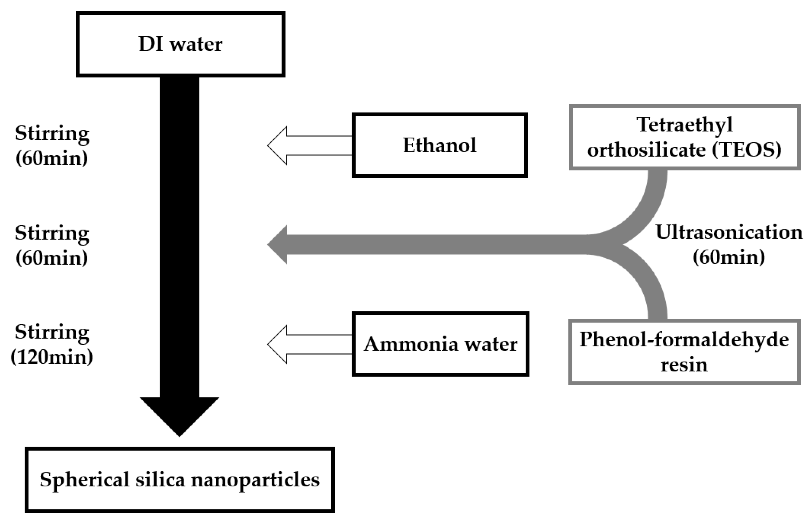
Figure 1 shows the manufacturing process for the silica particles. The phenol-formaldehyde resin was dispersed ultrasonically in tetraethyl orthosilicate (TEOS) for 60 min. Ethanol and DI water for the hydrolysis and condensation reactions were added to a round bottom flask and stirred at 600 rpm for 60 min. The phenol-formaldehyde resin/TEOS dispersion was injected into the ethanol/DI water solution and then stirred at 600 rpm for 60 min. Next, ammonia water was injected and stirred at 600 rpm for 120 min. The resulting solution was dried at 90 °C in a convection oven. Finally, the agglomerates of dried silica were ground to a powder. The content of the phenol-formaldehyde resin was changed to control the particle size of the silica. Three conditions were tested using 0.027 g, 0.030 g, and 0.033 g of the phenol-formaldehyde resin. Through this method, we prepared spherical silica nanoparticles. Additionally, spherical silica nanoparticles were prepared for comparison without injecting the phenol-formaldehyde resin. Table 1 shows the amounts of the reagents used in the synthesis of the spherical silica nanoparticles.
2.3. Coating and Synthesis of Silica Solutions
Figure 2 shows the coating process for producing structural color using silica solutions. It is impossible to arrange spherical silica nanoparticles in powder form amorphously. Therefore, silica powder was dispersed in a liquid and used in the liquid solution state. In our study, deionized water was used as the solvent. Silica powder was added to the DI water, and the concentration was adjusted to 0.1 g/mL. The resulting solution containing silica powder was dispersed for 4 h using an ultrasonic disperser. The silica solutions were then ready for use. The prepared silica solution was coated on an alcohol-washed glass slide (76 mm × 26 mm × 1 mm) to express the structural colors.
3. Experimental Results and Discussion
3.1. Spherical Silica Nanoparticles
Figure 3 shows the XRD patterns for the products synthesized by the sol-gel process. Each pattern shows a peak in the range of 15–30°. No additional peaks were found in other regions. The trend for these XRD patterns was the same as that for the silica obtained by the sol-gel process reported by Lin et al. [20]. The measured pattern (88%) was consistent with the SiO2 pattern reported in the crystallography open database (COD, no. 96-901-3492) [21]. We could confirm that the material produced using this method was SiO2.
Figure 4 presents the SEM images of the silica powder. Figure 4a shows a silica powder synthesized without the phenol-formaldehyde resin, and the silica particles show uniform spherical shapes and sizes. On the other hand, the silica powders in Figure 4b–d are synthesized with phenol-formaldehyde resin. Spherical or atypical particles were formed. Unlike Figure 4a, some necks are observed between the nanoparticles. This result was due to the phenol-formaldehyde resin.
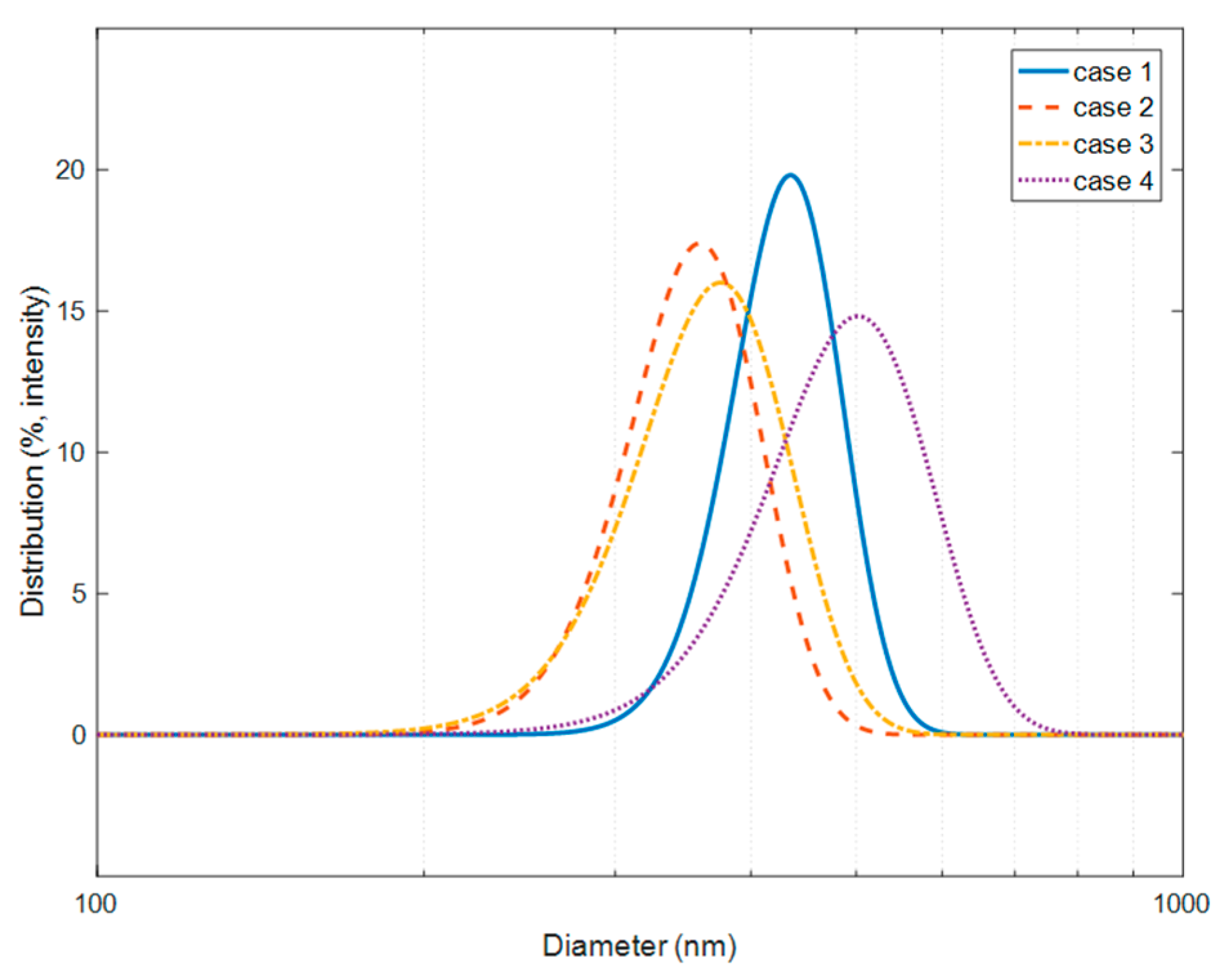
Figure 5 indicates the particle size distribution of the manufactured silica powders. Each silica powder was mixed with DI water at a concentration of 0.01 g/mL to determine the size of the particles. Subsequently, the mixture was ground in an ultrasonicator for 15 min. Next, the size of the silica particles was measured using a nano-micro particle size analyzer. The average size of the spherical silica nanoparticles without the phenol-formaldehyde resin was 435 nm (Case 1). Meanwhile, the average size of nanoparticles with the phenol-formaldehyde resin was 359 nm, 375 nm, and 502 nm, respectively (Case 2–4). Consequently, the average size of the silica nanoparticles increased with the increasing phenol-formaldehyde resin content.
Figure 6 shows photographs of the manufactured silica powders. The silica powder of Figure 6a shows an ivory white color typical of silica. The reason for this color was that light scattering off a single particle passes through the surrounding particles, causing multiple scatterings such that the intensity of the scattered light in all wavelengths is the same. Figure 6b–d shows the various structural colors depending on the sizes of the spherical silica nanoparticles. The spherical silica nanoparticles show a blue color at 359 nm, a green color at 375 nm, and red color at 502 nm. Owing to particle aggregation by neck formation and the presence of atypical silica in Figure 4b–d, silica powders show structural color. Aggregated particles suppress multiple scatterings and increase the size of the specific wavelength [14,18].
3.2. Coating of Silica Solutions
Figure 7 shows the SEM images of the silica solutions coated on a glass slide. Figure 7a shows a crystal lattice structure of a silica solution consisting of homogeneously sized, monodispersed, spherical silica nanoparticles. However, in the case of Figure 7b–d, silica particles are arranged in amorphous form instead of a lattice structure. The reason is that the particles of uniform size and shape were arranged in a crystal lattice without disturbing other particles during the self-assembly process. Meanwhile, the spherical silica nanoparticles did not form a lattice structure due to the presence of atypical silica.
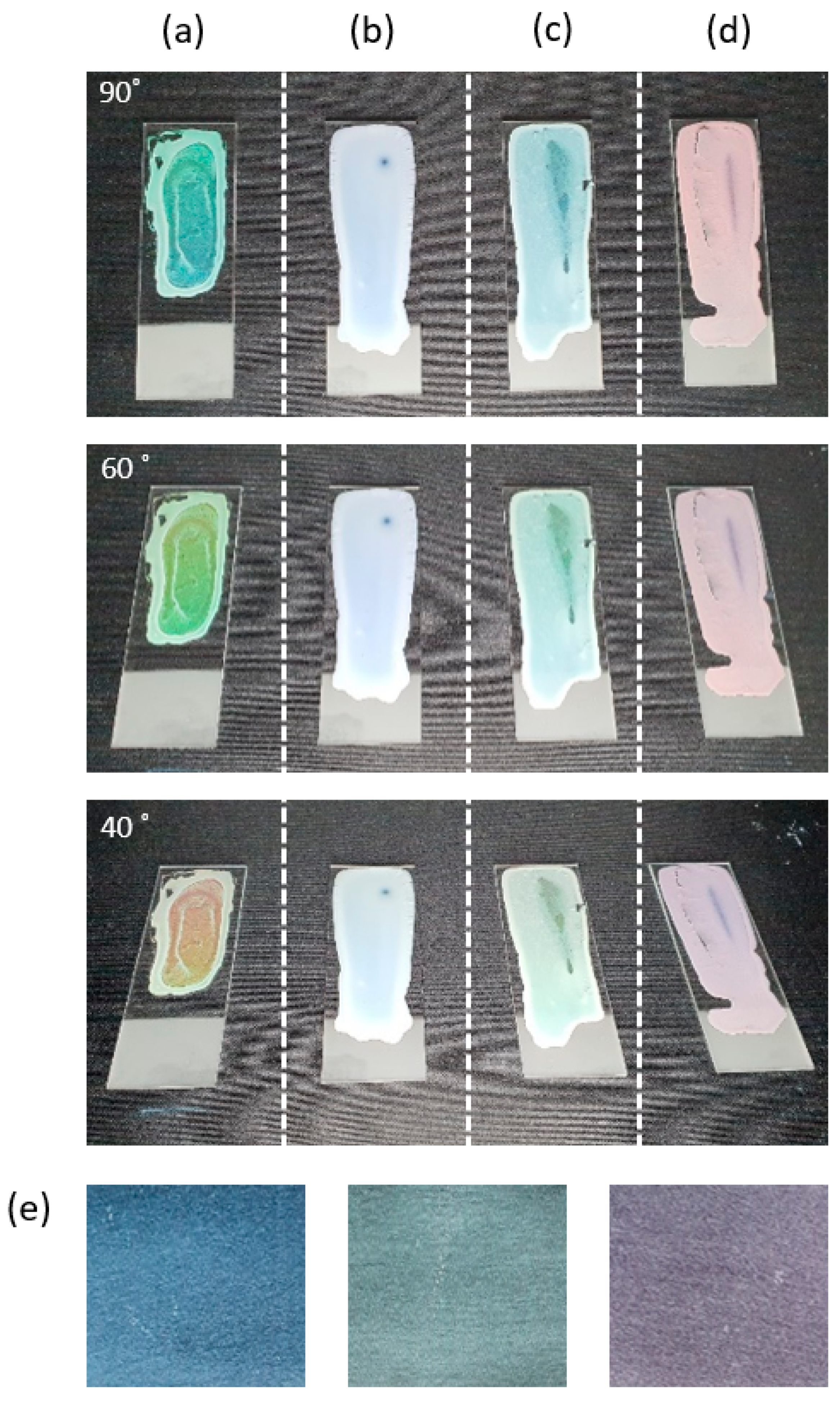
Figure 8 shows photographs of the coated silica solutions at three viewing angles and photographs of spherical silica nanoparticles rubbed on a black substrate. Figure 8a shows that the coated silica solution changes color to blue, green, and red at viewing angles of 90°, 60°, and 40°. These changes occurred because the crystal lattice structure in case 1 satisfied the Bragg’s equation (Equation (1) [11,22]).
where , , , and denote the size of the spherical silica nanoparticle, the reflection wavelength, the angle of light incidence, and the effective refractive index, respectively. As shown in Figure 4a, the average size of the spherical silica nanoparticles is 435 nm, and the effective refractive index is 1.35 [18]. The sizes of the particles were calculated theoretically from 438 nm to 704 nm with colors, as shown in Figure 8a. In contrast, in Figure 8b–d, the silica solutions coated on glass slides show a different color depending on the size of the spherical silica nanoparticles, and the same color as the silica powder is observed. Furthermore, the colors did not change with the change in the viewing angle. These results occurred because spherical silica nanoparticles did not form a crystal lattice structure, but formed an amorphous array due to particle aggregation, as shown in Figure 7b–d. That is, atypical silica particles interfered with the crystal arrangement of spherical silica nanoparticles. This amorphous array was similar to the arrangement induced by the addition of carbon black particles, and similar results were reported in Reference [14]. Figure 8e indicates that various colored membranes comprise solely of spherical silica nanoparticles. The average sizes of the particles were 300 nm, 400 nm, and 500 nm (from the left in the figure). It is confirmed that the color appeared differently according to the size of the spherical silica nanoparticles. The color of the silica solution coated in this study and the membrane color composed only of spherical silica nanoparticles showed similar trends to Reference [15].
4. Conclusions
The process of structural color fabrication is challenging, owing to the complicated specific conditions required. Thus, a simple fabricating method with low angle-dependence was proposed without using additional processes or particles. Atypical silica particles and spherical silica nanoparticles were synthesized simultaneously through a one-step process, and structural colors were produced by inducing an amorphous array. The one-step process used the sol-gel process in which TEOS and a small amount of phenol-formaldehyde were mixed before injecting the silica precursor. Subsequently, spherical silica nanoparticles and atypical silica particles were produced. Moreover, the size of the synthesized spherical silica nanoparticles increased proportionately with the amount of phenol-formaldehyde resin added. Similarly, the size of the atypical silica particles also increased. Atypical silica particles form necks between spherical silica nanoparticles and inhibit the formation of a crystal array. Consequently, silica powder shows a different color depending on the size of the spherical silica nanoparticles. On the contrary, silica powder without atypical silica particle appears ivory white. Synthesized silica powder was dispersed in DI water to obtain a photonic glass. Once the colloidal particles are separated and packed, it is difficult to redistribute the individual particles because the surface energy has already been reduced by aggregation. For this reason, aggregated silica particles were suspended in DI water due to the presence of atypical silica. Therefore, the coated silica solution showed the same color as the silica powder. We confirmed that the coated silica solution induced an amorphous arrangement from the SEM images. The results showed that the simple one-step method for fabricating a photonic glass produced structural colors that were independent of viewing angle.
Author Contributions
D.-S.C. participated in the experiment design, experiment, analysis, and writing. J.-H.C. participated in the experiment. C.-Y.L. participated in the supervision, project administration, and review. All authors have read and agreed to the published version of the manuscript.
Funding
This work was supported by the National Research Foundation of Korea (NRF) grant funded by the Korean Government (MSIT) (2017R1C1B2007217). This research was supported by the Basic Science Research Program through the National Research Foundation of Korea (NRF) funded by the Ministry of Education (2019R1I1 A3A01060180).
Conflicts of Interest
The authors declare no conflict of interest.
References
- Kinoshita, S.; Yoshioka, S. Structural colors in nature: The role of regularity and irregularity in the structure. Chem. Phys. Chem. 2005, 6, 1442–1459. [Google Scholar] [CrossRef] [PubMed]
- Fudouzi, H. Optical properties caused by periodical array structure with colloidal particles and their applications. Adv. Powder Technol. 2009, 20, 502–508. [Google Scholar] [CrossRef]
- Kriegel, I.; Scotognella, F. Indium tin oxide nanoparticle: Air layers for one-dimensional multilayer photonic structures. Appl. Sci. Basel 2019, 9, 2564. [Google Scholar] [CrossRef] [Green Version]
- Muller, M.; Zentel, R.; Maka, T.; Romanov, S.G.; Torres, C.M.S. Photonic crystal films with high refractive index contrast. Adv. Mater. 2000, 12, 1499–1503. [Google Scholar] [CrossRef]
- Li, Z.Y.; Zhang, Z.Q. Photonic bandgaps in disordered inverse-opal photonic crystals. Adv. Mater. 2001, 13, 433–436. [Google Scholar] [CrossRef]
- Liu, K.; Schmedake, T.A.; Tsu, R. A comparative study of colloidal silica spheres: Photonic crystals versus Bragg’s law. Phys. Lett. A 2008, 372, 4517–4520. [Google Scholar] [CrossRef]
- Kanamori, Y.; Katsube, H.; Furuta, T.; Hasegawa, S.; Hane, K. Design and fabrication of structural color filters with polymer-based guided-mode resonant gratings by nanoimprint lithography. Jpn. J. Appl. Phys. 2009, 48, 06FH04. [Google Scholar] [CrossRef]
- Mizeikis, V.; Mijulskas, I.; Tomasiunas, R.; Juodkazis, S.; Matsuo, S.; Misawa, H. Optical characteristics of two-dimensional photonic crystals in anodic aluminum oxide films. Jpn. J. Appl. Phys. 2004, 43, 36–43. [Google Scholar] [CrossRef]
- Ko, Y.L.; Tsai, H.P.; Lin, K.Y.; Chen, Y.C.; Yang, H. Reusable macroporous photonic crystal-based ethanol vapor detectors by doctor blade coating. J. Colloid Interface Sci. 2016, 487, 360–369. [Google Scholar] [CrossRef]
- Xiao, F.X.; Pagliaro, M.; Xu, Y.J.; Liu, B. Layer-by-layer assembly of versatile nanoarchitectures with diverse dimensionality: A new perspective for rational construction of multilayer assemblies. Chem. Soc. Rev. 2016, 45, 3088–3121. [Google Scholar] [CrossRef]
- Kuo, W.K.; Weng, H.P.; Hsu, J.J. Photonic crystal-based sensors for detecting alcohol concentration. Appl. Sci. 2016, 6, 67. [Google Scholar] [CrossRef]
- Yu, Y.; Fang, Z.; Ma, C.; Inoue, H.; Yang, G.; Zheng, S.; Chen, D.; Yang, Z.; Masuno, A.; Orava, J.; et al. Mesoscale engineering of photonic glass for tunable luminescence. NPG Asia Mater. 2016, 8, e318. [Google Scholar] [CrossRef] [Green Version]
- Armstrong, E.; O’Dwyer, C. Artificial opal photonic crystals and inverse opal structures—Fundamentals and applications from optics to energy storage. J. Mater. Chem. C 2015, 3, 2109–6143. [Google Scholar] [CrossRef] [Green Version]
- Forster, D.J.; Noh, H.; Liew, S.F.; Saranathan, V.; Schreck, C.F.; Yang, L.; Park, J.G.; O.Prum, R.; Mochrie, S.G.J.; O’Hern, C.S.; et al. Biomimetic isotropic nanostructures for structural coloration. Adv. Mater. 2010, 22, 2939–2944. [Google Scholar] [CrossRef] [Green Version]
- Takeoka, Y.; Yoshioka, S.; Takano, A.; Arai, S.; Nueangnoraj, K.; Nishhara, H.; Teshima, M.; Ohtsuka, Y.; Seki, T. Production of colored pigments with amorphous arrays of black and white colloidal particles. Angew. Chem. 2013, 125, 7402–7406. [Google Scholar] [CrossRef]
- Teshima, M.; Seki, T.; Kawano, R.; Takeuchi, S.; Yoshioka, S.; Takeoka, Y. Preparation of structurally colored, monodisperse spherical assemblies composed of black and white colloidal particles using a micro-flow-focusing device. J. Mater. Chem. C 2014, 3, 769–777. [Google Scholar] [CrossRef]
- Zhang, Y.; Dong, B.; Chen, A.; Lui, X.; Shi, L.; Zi, J. Using cuttlefish ink as an additive to produce non-iridescent structural colors of high color visibility. Adv. Mater. 2015, 27, 4719–4724. [Google Scholar] [CrossRef]
- Gokhan, T.; Tugrul, G.; Mustafa, G.; Mustafa, M.D. Non-iridescent structural colors from uniform-sized SiO2 colloids. Photonics Nanostruct. 2017, 29, 22–29. [Google Scholar]
- Qiao, W.; Li, S.; Guo, G.; Han, S.; Ren, S.; Ma, Y. Synthesis and characterization of phenol-formaldehyde resin using enzymatic hydrolysis lignin. J. Ind. Eng. Chem. 2015, 21, 1417–1422. [Google Scholar] [CrossRef]
- Lin, W.; Zheng, J.; Yan, L.; Zhang, X. Sol-gel preparation of self-cleaning SiO2-TiO2/SiO2-TiO2 double-layer antireflective coating for solar glass. Results Phys. 2018, 8, 532–536. [Google Scholar] [CrossRef]
- Patel, M.; Mukhopadhyday, I.; Ray, A. Annealing influence over structural and optical properties of sprayed SnS thin films. Opt. Mater. 2013, 35, 1693–1699. [Google Scholar] [CrossRef]
- Mayonado, G.; Mian, S.M.; Robbiano, V.; Cacialli, F. Investigation of the bragg-snell law in photonic crystals. In Proceedings of the 2015 Laboratory Instruction Beyond the First Year, College Park, MD, USA, 22–24 July 2015. [Google Scholar]
Figure 1.
The manufacturing process for silica nanoparticles.

Figure 2.
Coating process for the silica solutions.
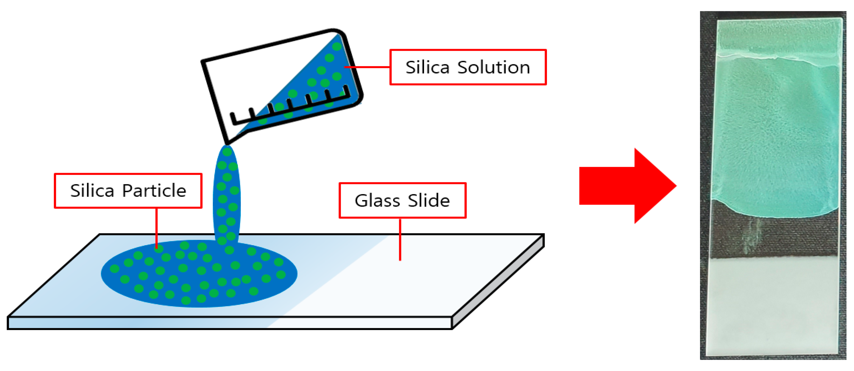
Figure 3.
X-ray diffraction (XRD) patterns of the silica powders. Case 1: No added phenol-formaldehyde resin; Case 2: 0.027 g of added phenol-formaldehyde resin; Case 3: 0.030 g of added phenol-formaldehyde resin; Case 4: 0.033 g of added phenol-formaldehyde resin.
Figure 3.
X-ray diffraction (XRD) patterns of the silica powders. Case 1: No added phenol-formaldehyde resin; Case 2: 0.027 g of added phenol-formaldehyde resin; Case 3: 0.030 g of added phenol-formaldehyde resin; Case 4: 0.033 g of added phenol-formaldehyde resin.
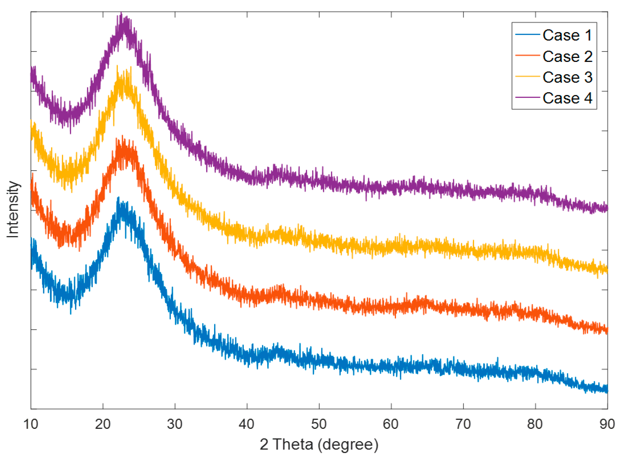
Figure 4.
Scanning electron microscopy (SEM) photographs of the silica powders: (a) No added phenol-formaldehyde resin (Case 1); (b) 0.027 g of added phenol-formaldehyde resin (Case 2); (c) 0.030 g of added phenol-formaldehyde resin (Case 3); (d) 0.033 g of added phenol-formaldehyde resin (Case 4).
Figure 4.
Scanning electron microscopy (SEM) photographs of the silica powders: (a) No added phenol-formaldehyde resin (Case 1); (b) 0.027 g of added phenol-formaldehyde resin (Case 2); (c) 0.030 g of added phenol-formaldehyde resin (Case 3); (d) 0.033 g of added phenol-formaldehyde resin (Case 4).
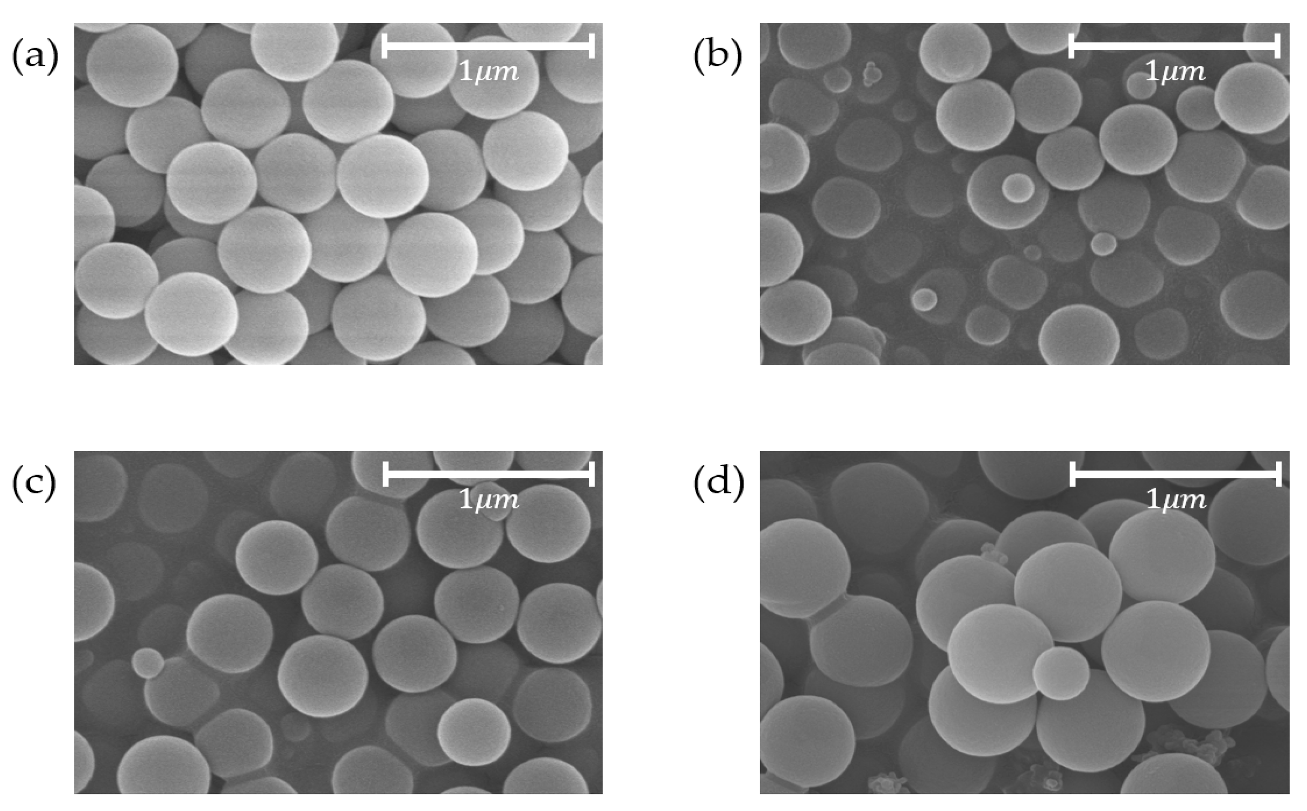
Figure 5.
Particle sizes of synthesized silica distributions. No added phenol-formaldehyde resin (Case 1); 0.027 g of added phenol-formaldehyde resin (Case 2); 0.030 g of added phenol-formaldehyde resin (Case 3); 0.033 g of added phenol-formaldehyde resin (Case 4).
Figure 5.
Particle sizes of synthesized silica distributions. No added phenol-formaldehyde resin (Case 1); 0.027 g of added phenol-formaldehyde resin (Case 2); 0.030 g of added phenol-formaldehyde resin (Case 3); 0.033 g of added phenol-formaldehyde resin (Case 4).

Figure 6.
Photographs of the silica powders: (a) No added phenol-formaldehyde resin (Case 1); (b) 0.027 g of added phenol-formaldehyde resin (Case 2); (c) 0.030 g of added phenol-formaldehyde resin (Case 3); (d) 0.033 g of added phenol-formaldehyde resin (Case 4).
Figure 6.
Photographs of the silica powders: (a) No added phenol-formaldehyde resin (Case 1); (b) 0.027 g of added phenol-formaldehyde resin (Case 2); (c) 0.030 g of added phenol-formaldehyde resin (Case 3); (d) 0.033 g of added phenol-formaldehyde resin (Case 4).
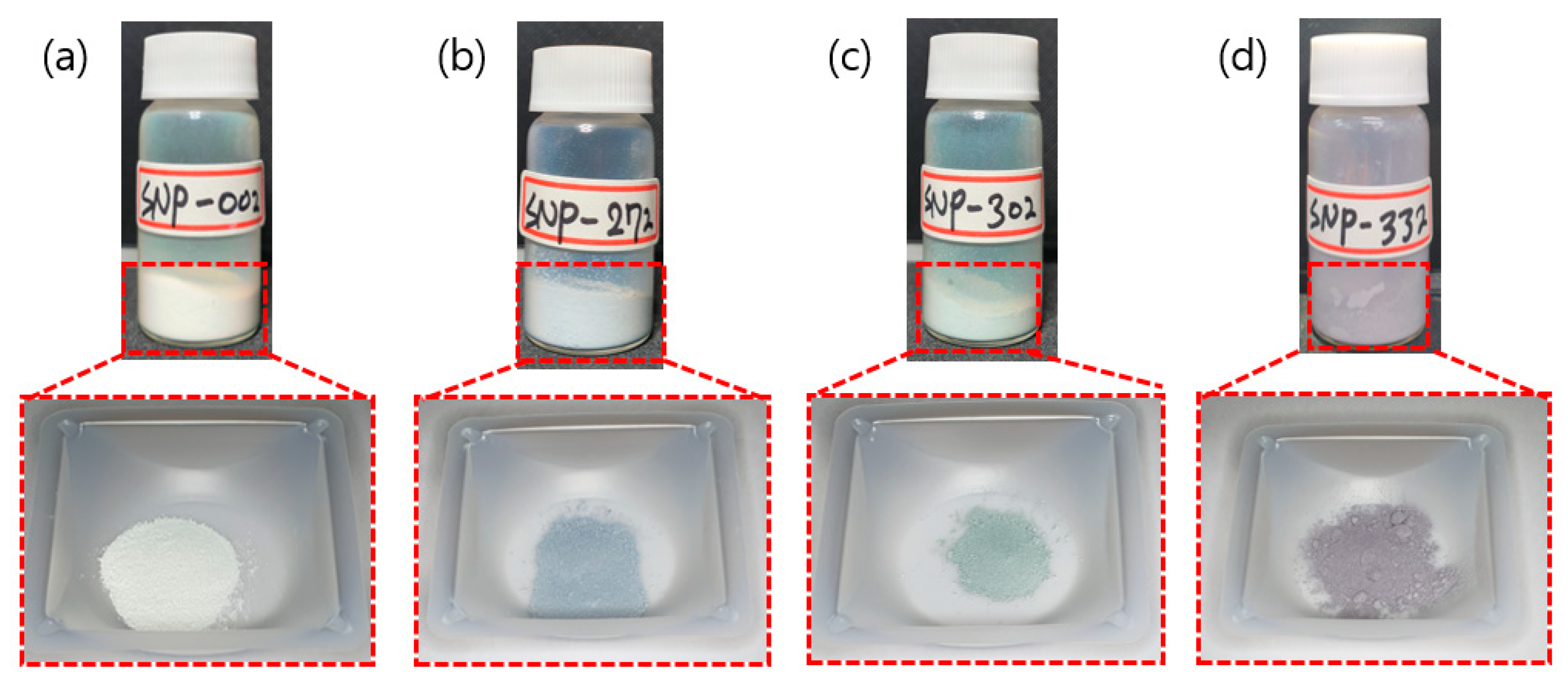
Figure 7.
SEM photographs of the silica solution coatings: (a) No added phenol-formaldehyde resin (Case 1); (b) 0.027 g of added phenol-formaldehyde resin (Case 2); (c) 0.030 g of added phenol-formaldehyde resin (Case 3); (d) 0.033 g of added phenol-formaldehyde resin (Case 4).
Figure 7.
SEM photographs of the silica solution coatings: (a) No added phenol-formaldehyde resin (Case 1); (b) 0.027 g of added phenol-formaldehyde resin (Case 2); (c) 0.030 g of added phenol-formaldehyde resin (Case 3); (d) 0.033 g of added phenol-formaldehyde resin (Case 4).
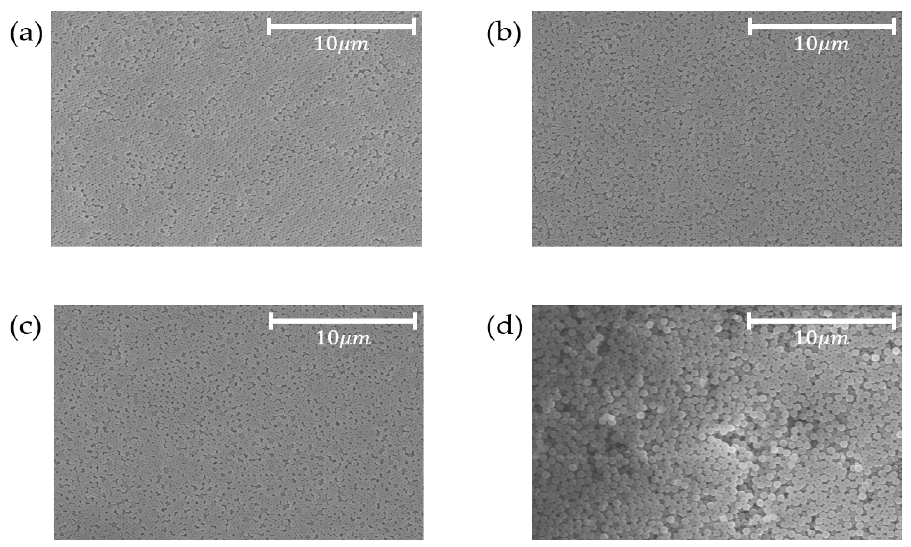
Figure 8.
Photographs of the silica solution coatings under three viewing angles: (a) Case 1 (various colors depending on angles); (b) Case 2 (blue); (c) Case 3 (green); (d) Case 4 (red); (e) Colored membranes consist of solely of spherical silica particles.
Figure 8.
Photographs of the silica solution coatings under three viewing angles: (a) Case 1 (various colors depending on angles); (b) Case 2 (blue); (c) Case 3 (green); (d) Case 4 (red); (e) Colored membranes consist of solely of spherical silica particles.

Table 1.
Reagents used in the synthesis of spherical silica nanoparticles.
| Sample | Phenol-Formaldehyde Resin [g] | TEOS [mL] | Ethanol [mL] | DI Water [mL] | Ammonia Water [mL] |
|---|---|---|---|---|---|
| Case 1 | - | 20 | 50 | 50 | 6 |
| Case 2 | 0.027 | 20 | 50 | 50 | 6 |
| Case 3 | 0.030 | 20 | 50 | 50 | 6 |
| Case 4 | 0.033 | 20 | 50 | 50 | 6 |
© 2020 by the authors. Licensee MDPI, Basel, Switzerland. This article is an open access article distributed under the terms and conditions of the Creative Commons Attribution (CC BY) license (http://creativecommons.org/licenses/by/4.0/).
Share and Cite
MDPI and ACS Style
Choi, D.-S.; Choi, J.-H.; Lee, C.-Y. Structural Colors Based on Amorphous Arrays Comprised Solely of Silica Particles. Appl. Sci. 2020, 10, 420. https://doi.org/10.3390/app10010420
AMA Style
Choi D-S, Choi J-H, Lee C-Y. Structural Colors Based on Amorphous Arrays Comprised Solely of Silica Particles. Applied Sciences. 2020; 10(1):420. https://doi.org/10.3390/app10010420
Chicago/Turabian StyleChoi, Dae-San, Ju-Hwan Choi, and Chang-Yull Lee. 2020. "Structural Colors Based on Amorphous Arrays Comprised Solely of Silica Particles" Applied Sciences 10, no. 1: 420. https://doi.org/10.3390/app10010420
Note that from the first issue of 2016, this journal uses article numbers instead of page numbers. See further details here.