Article

Rigorous Study on Hump Phenomena in Surrounding Channel Nanowire (SCNW) Tunnel Field-Effect Transistor (TFET)

1
Department of Electrical and Computer Engineering, Ajou University, Suwon 16499, Korea
2
Department of Electronic Engineering, Myongji University, Yongin 17058, Korea
3
School of Electrical Engineering, Pukyong National University, Busan 48513, Korea
*
Authors to whom correspondence should be addressed.
Appl. Sci. 2020, 10(10), 3596; https://doi.org/10.3390/app10103596
Submission received: 16 April 2020 / Revised: 15 May 2020 / Accepted: 18 May 2020 / Published: 22 May 2020
(This article belongs to the Special Issue New Aspects of Si-Based Material and Device)

Abstract

:
In this paper, analysis and optimization of surrounding channel nanowire (SCNW) tunnel field-effect transistor (TFET) has been discussed with the help of technology computer-aided design (TCAD) simulation. The SCNW TFET features an ultra-thin tunnel layer at source sidewall and shows a high on-current (ION). In spite of the high electrical performance, the SCNW TFET suffers from hump effect which deteriorates subthreshold swing (S). In order to solve the issue, an origin of hump effect is analyzed firstly. Based on the simulation, the transfer curve in SCNW TFET is decoupled into vertical- and lateral-BTBTs. In addition, the lateral-BTBT causes the hump effect due to low turn-on voltage (VON) and low ION. Therefore, the device design parameter is optimized to suppress the hump effect by adjusting thickness of the ultra-thin tunnel layer. Finally, we compared the electrical properties of the planar, nanowire and SCNW TFET. As a result, the optimized SCNW TFET shows better electrical performance compared with other TFETs.

1. Introduction

A reduction of power density in complementary metal-oxide-semiconductor (CMOS) technology becomes one of the major concerns as the CMOS devices have been scaled down [1], [2]. A tunnel FET (TFET) has been attracted as a substitutable device for an ultra-low power logic circuit since it can achieve subthreshold swing (S) less than 60 mV/decade at room temperature which allows TFET to be operated with the lower supply voltage (<0.5 V) maintaining a high on-off current ratio (ION/IOFF) [3,4,5,6]. However, experimental results have demonstrated that the TFET suffers from some critical issues such as low-level ION, ambipolar current and poor S [7,8]. There are several studies to address them with the help of narrow band gap materials [9,10,11], abrupt doping profile [12] and novel geometrical structures [13,14,15]. Among these studies, many papers propose a TFET with an ultra-thin tunnel layer at source sidewall which enables band-to-band tunneling (BTBT) perpendicular to the channel direction (vertical-BTBT) [16,17,18,19,20,21,22,23]. It can improve ION as well as S with the help of a large BTBT junction area and a short tunnel barrier width. However, it only considers a vertical-BTBT and ignores the other BTBT component including a BTBT parallel to the channel direction (lateral-BTBT), [24,25]. Since BTBT at sharp source corner is deeply related to the hump effect which degrades average S and ION, it should be examined rigorously for a device design optimization [26]. Therefore, more precise analysis are required considering both vertical- and lateral-BTBTs in technology computer-aided design (TCAD) simulation [27,28,29,30].
This paper is composed as follow. First of all, device design parameters and TCAD simulation conditions for a gate-all-around (GAA)-NW TFET with an ultra-thin tunnel layer at source sidewall are explained. Second, after examining the basic operation of studied TFET, a fundamental origin of hump effect is analyzed by two-dimensional (2D) contour plots. Third, the influences of geometrical parameters on hump effect are investigated and analyzed to minimize undesired effect which degrades switching performance. Last of all, the optimized structure is compared with the control devices.

2. Device Fabrication

The device structure used in this work is similar to that in [16], except a lateral channel direction considering the compatibility with the state-of-the-art CMOS technology for a sub-5 nm-technology nodes [31] (Figure 1). It is named as a surrounding channel nanowire (SCNW) TFET, since its intrinsic (or lightly doped) channel which is named as tunnel region surrounds conventional nanowire structure. All the materials except for gate oxide are Si. The gate oxide is SiO2. In TCAD simulation, a channel length (LCH) is set by 30 nm to exclude short-channel effect. Considering the latest CMOS technology, a nanowire radius except surrounding channel (i.e., tunnel region) (TB) and a gate oxide thickness (TOX) are set by 7 nm and 1 nm, respectively. The other important design parameters are summarized in Figure 1 and Table 1. All the parameter variations in this simulation are set in consideration of the fabrication processes [32,33]. The following models are used for an accurate simulation result: Shockey-Read-Hall recombination, doping and field dependent mobility, and dynamic non-local BTBT after calibration by referring [17]. Since the thickness of tunnel region (TTUN) is less than 8 nm, modified local density approximation is also used to consider quantum effect. In addition, the physical characteristics for BTBT is reflected by the calibrated current model based on the fabricated device [34,35,36,37]. For the calculation of BTBT generation rate (G) per unit volume in uniform electric field, Kane’s model is use as follows:
G = A ( F F 0 ) P exp ( B F ) ,
where F0 = 1 V/m, P = 2.5 for indirect BTBT, A = 4.0 × 1014 cm−1·s−1, and B = 1.9 × 10⁷ V·cm−1 are the Kane’s model parameters and F is the electric field [34]. The pre-factor A and the exponential factor B parameter are calibrated by referring [17].

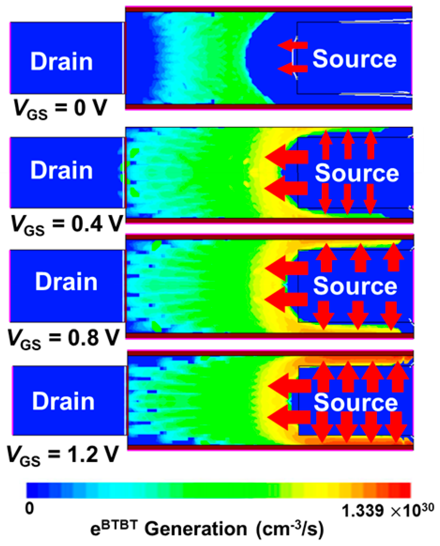
3. Hump Effect in SCNW TFET

Figure 2 shows drain current (ID) versus gate voltage (VGS) curves with 2 nm-TTUN and 0.5 V-drain voltage (VDS) while LTUN is varied from 20 to 60 nm. The ION is extracted at 2.0 V-VGS and 0.5 V-VDS. The ION increases linearly proportional to the LTUN which confirms that the BTBT junction area of SCNW TFET is determined by the LTUN. Generally, the FETs based on a NW channel have a disadvantage for enhancing current drivability, which can be achieved by increasing a NW radius or using a multi-channel structure [38]. On the other hand, SCNW TFET can easily adjust ION by controlling a LTUN. However, as shown in Figure 3a, there is a hump in the subthreshold region of SCNW TFET. The transfer curves are simulated with various VDS values. At all the VDS values, the hump current appears. In addition to this, with the higher the doping concentration, the better the ON-current is shown however, the hump effect is noticeable from 5×10¹⁹-NS cm−3 as shown in Figure 3b. The hump effect should be addressed for TFET’s low-power application since it deteriorates average S which results in the degradation of ION/IOFF and/or supply power (VDD)-scaling. Therefore, optimization for other parameters is needed to achieve high ON-current and hump-less transfer curve. In order to analyze the cause of hump effect, the electron BTBT generation rates (eBTBT) are examined by 2D contour plots with different VGS conditions (Figure 4). When VGS is applied near a turn-ON voltage (VON), defined as VGS when BTBT starts to occur, a lateral-BTBT is predominant. As VGS increases, a vertical-BTBT starts to occur at 0.4 V-VGS and finally surpasses the lateral-BTBT at 1.2 V-VGS. Therefore, the current of SCNW TFET can be decoupled into two different BTBTs. In addition, transfer curves with various LTUN are plotted in Figure 5. The ID at low VGS (< 0.9 V) is unchanged regardless of LTUN, while ID increases with longer LTUN at high VGS (> 0.9 V). The VGS at this point is defined as hump voltage (VHUMP). Since the tunnel junction area of vertical-BTBT component is only affected by LTUN.

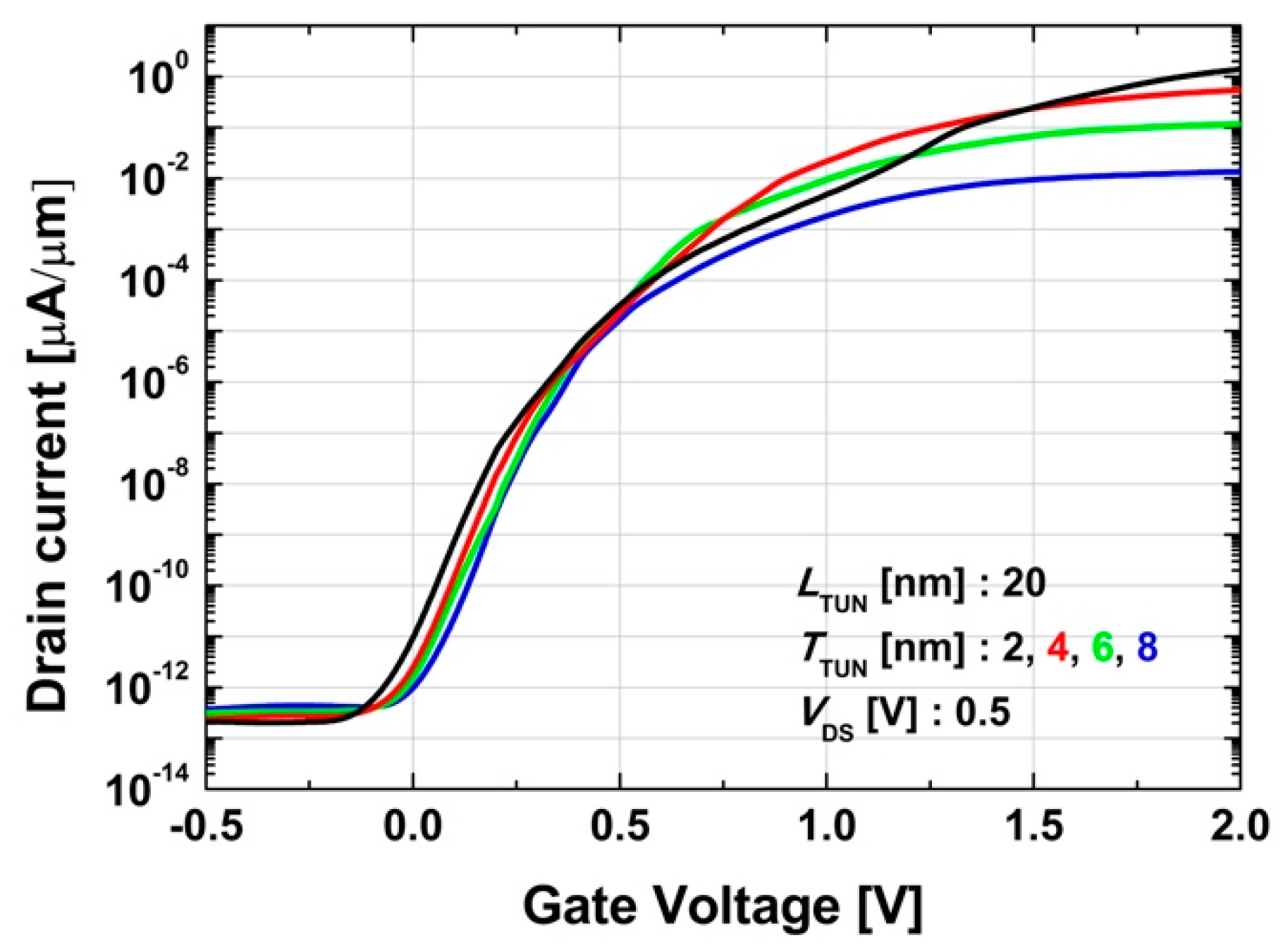
4. Device Optimization

In Section 3, we confirmed that the hump behavior in SCNW TFET is mainly attributed to the two BTBT paths (i.e., vertical and lateral) which have different VON and BTBT rates. Therefore, a design optimization is needed to achieve maximum electrical performance (low S and high ION). In this Section, the influences of LTUN and TTUN on SCNW TFET’s electrical characteristic are investigated since the vertical-BTBT mostly occurs in the tunnel region. Figure 6a shows transfer curves with 50, 80, 100 nm of LTUN and 2, 3, 4, 5 nm of TTUN. As shown in the inset of Figure 6a, the VHUMP is clearly decreased as TTUN increases. The results can be quantitatively analyzed and calculated by voltage division model in which the gate oxide and depletion capacitors (Cox and CSi) are connected in series (Figure 6b) [13]. Since TTUN is ultra-thin (< 10 nm) and source is highly doped, it can be assumed that the tunnel region is entirely depleted; the CSi is constant. Therefore, surface potential ( ψ S ) is expressed as (2), where ε Si and ε ox are permittivity of Si and SiO2, respectively. If TTUN increases, ψ S becomes large and vertical-BTBT occurs with the smaller VGS which results in the decrease of VHUMP as discussed in Figure 6a.
ψ s = C ox C ox + C si V GS = ε ox T ox ε ox T ox + ε Si T tun V GS = 1 1 + 3 T ox T tun V GS ψ s = V GS 3 T ox T tun + 3 T ox V GS ,   where   ε Si 3 ε ox  
Figure 7 shows transfer curves with various TTUN from 2 to 8 nm, where LTUN and VDS are fixed at 20 nm and 0.5 V, respectively. According to the results, the ID is clearly increased, and S is deteriorated as TTUN becomes thinner. It is attributed to the enhanced vertical-BTBT rate with the smaller TTUN, because the tunnel resistance (i.e., tunnel barrier width) of SCNW TFET is geometrically determined by the TTUN [39]. However, an aggressive scaling-down of TTUN is contradictory to the process capability and the S which gets worse as the TTUN decreases due to an increased VHUMP. Consequently, an optimization of TTUN can be a strategy for SCNW TFET to compensate its weakness (i.e., low ION and hump effect) and/or enhance its strength (i.e., under 60 mV/dec-S at room temperature). Finally, TTUN is optimized as 4 nm. Then, the performances of planar TFET, SCNW TFETs and nanowire TFET are compared. Figure 8a shows the average subthreshold swing (Savg) and point-to-point minimum subthreshold swing (Smin) of SCNW, nanowire and planar TFETs. The Savg is defined as the average inverse slope of the transfer curve while ID changes from 10−12 μA/ μm to 10−2 μA/ μm. For Smin, the planar TFET, SCNW TFETs and nanowire TFET show similar values, all of which are less than 60 mV/dec. For Savg, SCNW TFET shows the lowest value. Figure 8b shows transfer curve of planar TFET, SCNW TFETs and nanowire TFET. For fair comparison, the IOFF of these devices should be adjusted to the same level. The above adjustment is achieved by changing the work function and channel doping concentration. The adjusted IOFF is 10−7 μA/μm, referring to actual IOFF in nanowire TFET [40]. The Figure 8b shows that the SCNW TFET has a larger ION than that of the planar and nanowire TFETs. In detail, its ION is enhanced 2.4 times more than that of nanowire TFET and 4.7 times more than that of planar TFET. In addition, the SCNW TFET shows higher ION than other devices at 0.53 V-VGS and fully operates within 0.7 V-VGS.

5. Conclusions

The SCNW TFET has been studied for high electrical performance. It features nanowire TFET with a thin tunnel layer at source region. Based on the simulation, the transfer curve in SCNW TFET is analyzed and decoupled into vertical- and lateral-BTBTs. The vertical-BTBT is attributed to excellent ION rate and S. However, the lateral-BTBT causes the hump effect due to low VON and low ION. Therefore, the design optimization is suggested to reduce the hump effect and achieve maximum electrical performance (low S and high ION). Finally, the electrical performance without hump effect is optimized by adjusting the thin tunnel layer. In future work, novel design strategy to reduce lateral-BTBT will be suggested to eliminate the hump effect.

Author Contributions

Writing-Original Draft & Data curation, S.-H.L. and J.-U.P.; Formal analysis, G.K. and D.-W.J.; Writing-Review & Editing, J.H.K. and S.K.; Validation J.H.K.; Supervision S.K. All authors have read and agreed to the published version of the manuscript.

Funding

This research was supported in part by the Ajou University research fund, in part by the Brain Korea 21 Plus Project, in part by the MOTIE/KSRC under Grant 10080575 (Future Semiconductor Device Technology Development Program), and in part by the NRF of Korea funded by the MSIT under Grant NRF-2019M3F3A1A03079739 and NRF-2019M3F3A1A02072091 (Intelligent Semiconductor Technology Development Program). The EDA tool was supported by the IC Design Education Center (IDEC), Korea.

Conflicts of Interest

The authors declare no conflict of interest.

References

  1. Sakurai, T. Perspectives of low-power VLSI’s. IEICE Trans. Electron. 2004, E87-C, 429–436. [Google Scholar]
  2. Seabaugh, A.C.; Zhang, Q. Low-voltage tunnel transistors for beyond CMOS logic. Proc. IEEE 2010, 98, 2095–2110. [Google Scholar] [CrossRef]
  3. Choi, W.Y.; Park, B.G.; Lee, J.D.; Liu, T.J.K. Tunneling field-effect transistors (TFETs) with subthreshold swing (SS) less than 60 mV/dec. IEEE Electron Device Lett. 2007, 28, 743–745. [Google Scholar] [CrossRef]
  4. Bernstein, K.; Cavin, R.K.; Porod, W.; Seabaugh, A.; Welser, J. Device and architecture outlook for beyond CMOS switches. Proc. IEEE 2010, 98, 2169–2184. [Google Scholar] [CrossRef]
  5. Lattanzio, L.; De Michielis, L.; Ionescu, A.M. Complementary germanium electron-hole bilayer tunnel FET for sub-0.5-V operation. IEEE Electron Device Lett. 2012, 33, 167–169. [Google Scholar] [CrossRef]
  6. Cheng, W.; Liang, R.; Xu, G.; Yu, G.; Zhang, S.; Yin, H.; Zhao, C.; Ren, T.L.; Xu, J. Fabrication and characterization of a novel Si line tunneling TFET with high drive current. IEEE J. Electron Devices Soc. 2020, 8, 336–340. [Google Scholar] [CrossRef]
  7. Seabaugh, A. The tunneling transistor. IEEE Spectr. 2013, 50, 34–62. [Google Scholar] [CrossRef]
  8. Joshi, T.; Singh, B.; Singh, Y. Controlling the ambipolar current in ultrathin SOI tunnel FETs using the back-bias effect. J. Comput. Electron. 2020. [Google Scholar] [CrossRef]
  9. Sung, H.K.; Kam, H.; Hu, C.; Liu, T.J.K. Germanium-source tunnel field effect transistors with record high I ON/IOFF. In Proceedings of the Digest of Technical Papers—Symposium on VLSI Technology, Honolulu, HI, USA, 15–17 June 2009; pp. 178–179. [Google Scholar]
  10. Mayer, F.; Le Royer, C.; Damlencourt, J.F.; Romanjek, K.; Andrieu, F.; Tabone, C.; Previtali, B.; Deleonibus, S. Impact of SOI, Si1-xGexOI and GeOI Substrates on CMOS Compatible Tunnel FET performance. In Proceedings of the 2008 IEEE International Electron Devices Meeting, San Francisco, CA, USA, 15–17 December 2008; ISBN 9781424423781. [Google Scholar]
  11. Villalon, A.; Le Royer, C.; Nguyen, P.; Barraud, S.; Glowacki, F.; Revelant, A.; Selmi, L.; Cristoloveanu, S.; Tosti, L.; Vizioz, C.; et al. First demonstration of strained SiGe nanowires TFETs with ION beyond 700μA/μm. In Proceedings of the Digest of Technical Papers—Symposium on VLSI Technology, Honolulu, HI, USA, 9–12 June 2014; pp. 1–2. [Google Scholar]
  12. Ionescu, A.M.; Riel, H. Tunnel field-effect transistors as energy-efficient electronic switches. Nature 2011, 479, 329–337. [Google Scholar] [CrossRef]
  13. Kim, S.W.; Kim, J.H.; Liu, T.J.K.; Choi, W.Y.; Park, B.G. Demonstration of L-Shaped Tunnel Field-Effect Transistors. IEEE Trans. Electron Devices 2016, 63, 1774–1778. [Google Scholar] [CrossRef]
  14. Toh, E.H.; Wang, G.H.; Samudra, G.; Yeo, Y.C. Device physics and design of double-gate tunneling field-effect transistor by silicon film thickness optimization. Appl. Phys. Lett. 2007, 90, 263507. [Google Scholar] [CrossRef]
  15. Verhulst, A.S.; Vandenberghe, W.G.; Maex, K.; Groeseneken, G. Tunnel field-effect transistor without gate-drain overlap. Appl. Phys. Lett. 2007, 91, 53102. [Google Scholar] [CrossRef]
  16. Seo, J.H.; Yoon, Y.J.; Lee, S.; Lee, J.H.; Cho, S.; Kang, I.M. Design and analysis of Si-based arch-shaped gate-all-around (GAA) tunneling field-effect transistor (TFET). Curr. Appl. Phys. 2015, 15, 208–212. [Google Scholar] [CrossRef]
  17. Kao, K.H.; Verhulst, A.S.; Vandenberghe, W.G.; Soree, B.; Groeseneken, G.; De Meyer, K. Direct and indirect band-to-band tunneling in germanium-based TFETs. IEEE Trans. Electron Devices 2012, 59, 292–301. [Google Scholar] [CrossRef]
  18. Kao, K.H.; Verhulst, A.S.; Vandenberghe, W.G.; Sorée, B.; Magnus, W.; Leonelli, D.; Groeseneken, G.; De Meyer, K. Optimization of gate-on-source-only tunnel FETs with counter-doped pockets. IEEE Trans. Electron Devices 2012, 59, 2070–2077. [Google Scholar] [CrossRef]
  19. Kao, K.H.; Verhulst, A.S.; Vandenberghe, W.G.; De Meyer, K. Counterdoped pocket thickness optimization of gate-on-source-only tunnel FETs. IEEE Trans. Electron Devices 2013, 60, 6–12. [Google Scholar] [CrossRef]
  20. Betti Beneventi, G.; Gnani, E.; Gnudi, A.; Reggiani, S.; Baccarani, G. Optimization of a pocketed dual-metal-gate TFET by means of TCAD simulations accounting for quantization-induced bandgap widening. IEEE Trans. Electron Devices 2015, 62, 44–51. [Google Scholar] [CrossRef]
  21. Asai, H.; Mori, T.; Matsukawa, T.; Hattori, J.; Endo, K.; Fukuda, K. Steep switching less than 15 mV dec-1 in silicon-on-insulator tunnel FETs by a trimmed-gate structure. Jpn. J. Appl. Phys. 2019, 58, SBBA16. [Google Scholar] [CrossRef]
  22. Ashita; Loan, S.A.; Rafat, M. A High-Performance Inverted-C Tunnel Junction FET with Source-Channel Overlap Pockets. IEEE Trans. Electron Devices 2018, 65, 763–768. [Google Scholar] [CrossRef]
  23. Devi, W.V.; Bhowmick, B.; Pukhrambam, P.D. Investigation of dual MOSCAP TFET with improved vertical tunneling and its near infra-red sensing application. Semicond. Sci. Technol. 2020. [Google Scholar] [CrossRef]
  24. Software, D.S. ATLAS User’ s Manual; Scientific Software Development GmbH: Santa Clara, CA, USA, 2010; Volume II. [Google Scholar]
  25. Shaker, A.; Maged, A.; Elshorbagy, A.; AbouElainain, A.; Elsabbagh, M. Source-all-around tunnel field-effect transistor (SAA-TFET): Proposal and design. Semicond. Sci. Technol. 2019, 35, 25007. [Google Scholar] [CrossRef]
  26. Kim, S.W.; Choi, W.Y. Hump Effects of Germanium/Silicon Heterojunction Tunnel Field-Effect Transistors. IEEE Trans. Electron Devices 2016, 63, 2583–2588. [Google Scholar] [CrossRef]
  27. Synopsys Inc. Sentaurus Device User Guide-v.K-2015.06; Synopsys Inc.: Mountain View, CA, USA, 2009. [Google Scholar]
  28. Knoch, J. Optimizing tunnel FET performance—Impact of device structure, transistor dimensions and choice of material. In Proceedings of the International Symposium on VLSI Technology, Systems, and Applications, Hsinchu, Taiwan, 27–29 April 2009; pp. 45–46. [Google Scholar]
  29. Alper, C.; Palestri, P.; Padilla, J.L.; Ionescu, A.M. The electron-hole bilayer TFET: Dimensionality effects and optimization. IEEE Trans. Electron Devices 2016, 63, 2603–2609. [Google Scholar] [CrossRef]
  30. Ko, E.; Lee, H.; Park, J.D.; Shin, C. Vertical tunnel FET: Design optimization with triple metal-gate Layers. IEEE Trans. Electron Devices 2016, 63, 5030–5035. [Google Scholar] [CrossRef]
  31. Singh, N.; Agarwal, A.; Bera, L.K.; Liow, T.Y.; Yang, R.; Rustagi, S.C.; Tung, C.H.; Kumar, R.; Lo, G.Q.; Balasubramanian, N.; et al. High-performance fully depleted silicon nanowire (diameter ≤ 5 nm) gate-all-around CMOS devices. IEEE Electron Device Lett. 2006, 27, 383–386. [Google Scholar] [CrossRef]
  32. Duffy, R.; Meaney, F.; Galluccio, E. Doping considerations for finfet, gate-all-around, and nanosheet based devices. ECS Trans. 2020, 97, 63–74. [Google Scholar] [CrossRef]
  33. Hazbun, R.; Hart, J.; Hickey, R.; Ghosh, A.; Fernando, N.; Zollner, S.; Adam, T.N.; Kolodzey, J. Silicon epitaxy using tetrasilane at low temperatures in ultra-high vacuum chemical vapor deposition. J. Cryst. Growth 2016, 444, 21–27. [Google Scholar] [CrossRef]
  34. Smets, Q.; Verhulst, A.S.; El Kazzi, S.; Gundlach, D.; Richter, C.A.; Mocuta, A.; Collaert, N.; Thean, A.V.Y.; Heyns, M.M. Calibration of the effective tunneling bandgap in GaAsSb/InGaAs for improved TFET performance prediction. IEEE Trans. Electron Devices 2016, 63, 4248–4254. [Google Scholar] [CrossRef]
  35. Verhulst, A.S.; Verreck, D.; Smets, Q.; Kao, K.H.; Van De Put, M.; Rooyackers, R.; Sorée, B.; Vandooren, A.; De Meyer, K.; Groeseneken, G.; et al. Perspective of tunnel-FET for future low-power technology nodes. In Proceedings of the Technical Digest—International Electron Devices Meeting, IEDM, San Francisco, CA, USA, 15–17 December 2014. [Google Scholar]
  36. Kranthi, N.K.; Shrivastava, M. ESD Behavior of Tunnel FET Devices. IEEE Trans. Electron Devices 2017, 64, 28–36. [Google Scholar] [CrossRef]
  37. Madan, J.; Chaujar, R. Interfacial charge analysis of heterogeneous gate dielectric-gate all around-tunnel FET for improved device reliability. IEEE Trans. Device Mater. Reliab. 2016, 16, 227–234. [Google Scholar] [CrossRef]
  38. Zhu, H.; Li, Q.; Yuan, H.; Baumgart, H.; Ioannou, D.E.; Richter, C.A. Self-aligned multi-channel silicon nanowire field-effect transistors. Solid-State Electron. 2012, 78, 92–96. [Google Scholar] [CrossRef]
  39. Kim, S.W.; Choi, W.Y.; Sun, M.C.; Kim, H.W.; Park, B.G. Design guideline of Si-based L-shaped tunneling field-effect transistors. Jpn. J. Appl. Phys. 2012, 51, 06FE09. [Google Scholar] [CrossRef]
  40. Gandhi, R.; Chen, Z.; Singh, N.; Banerjee, K.; Lee, S. Vertical Si-Nanowire n-type tunneling FETs with low subthreshold swing ≤ 50 mV/decade) at room temperature. IEEE Electron Device Lett. 2011, 32, 437–439. [Google Scholar] [CrossRef]
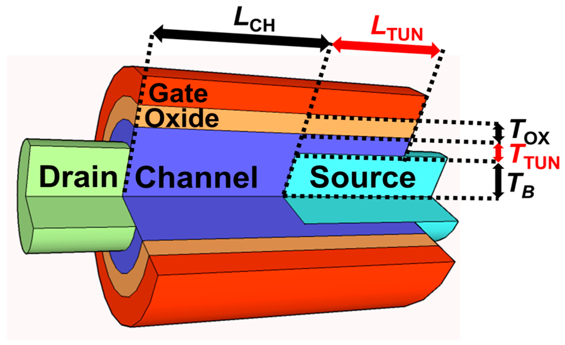
Figure 1. Schematic structure diagram and definitions of design parameters in SCNW TFET.
Applsci 10 03596 g001
Figure 2. (Simulation) ID-VGS curves of SCNW TFET with 2 nm-TTUN and 0.5 V-VDS depending on the LTUN. The inset shows ION as a function of LTUN. For the SCNW TFET, the ION increases proportional to LTUN.
Applsci 10 03596 g002
Figure 3. (Simulation) Log(ID)-VGS curves of SCNW TFET depending on the (a) VDS (b) NS. In spite of changing VDS and NS, the hump effect still remains.
Applsci 10 03596 g003
Figure 4. (Simulation) eBTBT of SCNW TFET as VGS increases from 0 to 1.2 V with 0.4 V step. TTUN = 2 nm, LTUN = 20 nm, and VDS = 0.5 V.
Applsci 10 03596 g004
Figure 5. (Simulation) Log(ID)-VGS curves of the SCNW TFET when the LTUN varies between 50, 80 and 100 nm.
Applsci 10 03596 g005
Figure 6. (Simulation) (a) Log(ID)-VGS curves of SCNW TFET according to TTUN with the various LTUN. The inset shows that the VHUMP is clearly decreased as TTUN increases. (b) (Calculation) The capacitance model in the area of SCNW TFET where vertical-BTBT occurs.
Applsci 10 03596 g006
Figure 7. (Simulation) Log(ID)-VGS curves of the SCNW TFET with various TTUN. The hump effect appears clearly, and S is deteriorated as TTUN becomes thinner.
Applsci 10 03596 g007
Figure 8. (Simulation) (a) Savg and Smin (b) ID-VGS curves of planar TFET, SCNW TFETs and nanowire TFET.
Applsci 10 03596 g008
Table 1. SCNW TFET design parameters used for TCAD simulation.
ParametersValue
Source doping concentration, p-type (NS)1020 cm−3
Drain doping concentration, n-type (ND)1020 cm−3
Body doping concentration, p-type (NCH)1017 cm−3
Gate work function4.05 eV
Channel length (LCH)30 nm
Nanowire radius except tunnel region (TB)7 nm
Gate oxide thickness (TOX)1 nm
Length of tunnel region (LTUN)Variable
Thickness of tunnel region (TTUN)Variable
Drain voltage (VDS)0.5 V

