Numerical Investigation of Blast Performance of Plate-Reinforced Moment-Resisting Connection Using Large Concrete Filled Tubular Section


1
Department of Architectural Engineering, Catholic Kwandong University, Gangneung 25601, Korea
2
Department of Civil and Environmental Engineering, Hanyang University, Seoul 04763, Korea
3
School of Architecture and Architectural Engineering, Hanyang University, Ansan 15588, Korea
*
Author to whom correspondence should be addressed.
Appl. Sci. 2020, 10(11), 3700; https://doi.org/10.3390/app10113700
Submission received: 27 April 2020
/
Revised: 18 May 2020
/
Accepted: 20 May 2020
/
Published: 27 May 2020
(This article belongs to the Section Civil Engineering)
Abstract
:This paper presents a numerical study to investigate the blast performance of a plate-reinforced moment-resisting connection using a large concrete filled tubular (CFT) column with dimensions of 1000 × 1000 mm and a thickness of 40 mm. A steel H-section with dimensions of 700 × 300 × 13 × 24 mm is used for beam. The plate-reinforced large CFT connection is analyzed numerically using a finite element code to evaluate its blast resistance. The methodology of modeling the connection is validated based on a past experimental study and verified using an alternate finite element code. Five improvised explosive devices (IED) are considered as blast loadings. The blast resistance of the proposed connection against the IED attacks is investigated based on the design criteria specified in the U.S. government document, UFC 3-340-02, and in comparison to that of a widely used through-diaphragm moment connection. Local failure modes in the vicinity of the connections are also examined. Recommendation is provided for design practice.
1. Introduction
Moment resisting beam-column connections for buildings typically consist of steel H-section members because of their stable structural performance and good workability during construction. The connections using hollow structural sections (HSSs) have been used rarely at construction sites due to their worse workability and complex details for connecting beams to columns, e.g., [1,2,3]. However, with development of construction technologies, including one-way bolts, a wide variety of studies to develop moment-resisting connections using the HSS or concrete-filled tubular (CFT) section have been performed, e.g., [3,4,5,6,7,8,9,10].
The CFT section, comprising HSS and infilled concrete, is a composite structural system that makes good use of the merits of steel and concrete, namely, high tensile strength and ductility for steel and high compressive strength for concrete. This CFT section has been recently used in engineering applications including tall buildings, bridges, and plant facilities, e.g., [5,11]. The interaction between the HSS and concrete enables the delay of the local buckling of the HSS by preventing the strength degradation of beam to column connection, and the increase of the concrete compressive strength by the confinement effect of the HSS. In addition, since the steel plate is positioned at the perimeter of the CFT section, the flexural performance of the HSS is maximized. This CFT construction requires no formwork, reducing the construction period and the corresponding cost, because the HSS serves as a form for concrete placement.
Connection details with the CFT sections, used commonly on the construction site, are those reinforced with a through-diaphragm, internal diaphragm, and external diaphragm, as shown in Figure 1, e.g., [4,12,13,14,15,16]. Kurobane et al. [12] provided a design guide for structural HSS connections, where various HSS moment-resisting connections with a through-diaphragm, reduced beam section (RBS), internal diaphragm, external diaphragm, and end plate are available. More recently, Kim et al. [6] proposed a CFT connection detail using a vertical diaphragm, but the gravity load tests showed that the structural performance of the connection was not obtained due to the welding failure on the beam flange. This welding problem has been one of the primary issues in the conventional HSS and CFT connection details. Jin et al. [3] proposed a new seismic connection using a square HSS and H-beam. This connection was developed to resolve the issue of welding failure so that the beam and column in the proposed connection were connected only using one-way bolts, without welding. Although this connection was validated experimentally for their rotational capacity and the construction workability was dramatically improved, the problems of the integrity of the column whose upper, mid, and lower parts are connected by bolts have been raised continuously. Efforts need to be made to improve the details of the CFT connections.
With rising heights of buildings, larger column sizes have been required, and sizes of HSS up to a width of 1000 mm and a thickness of 40 mm are currently available, e.g., [17]. However, there has been little information in the open literature to apply the large HSS to the beam-column connections of buildings. Furthermore, increasing terrorist threats since the 9/11 attacks have required an assessment of the blast resistance of connections for design of high-rise buildings and safety-related structures such as nuclear power plants, chemical facilities, bridges, banks, and government facilities.
This paper presents a numerical study to investigate the blast performance of a pate-reinforced connection using a large square CFT column with dimensions of 1000 × 40 mm and a H-beam with dimensions of 700 × 300 × 13 × 24 mm. The reinforcing plate, used by Kim et al. [18] for moment connections with steel H-section columns, is herein adopted to secure the structural performance of the proposed connection.
Blast analysis for the proposed plate-reinforced connection is conducted using a finite element (FE) code, LS-DYNA [19], where the numerical model involves the effect of strain rate and material erosion. Various improvised explosive devices (IED) with scaled distances ranged from 0.2 to 0.98 m/kg1/3 are considered. Blast loadings for the IEDs are modeled in LS-DYNA using Load Blast Enhanced (LBE) [19] assuming hemispherical surface burst, noting that the LBE has been based on ConWep [20] and UFC 3-340-02 [21]. They are verified based on design charts available in the U.S. government document, UFC 3-340-02 [21]. The accuracy of the numerical model of the connection is validated using past experimental data of Lee [16] and is verified with an alternate finite element code, ABAQUS [22]. The blast performance for the proposed connection is investigated using design criteria specified in UFC 3-340-02 for end rotation of a member. Failure modes caused by IED explosions are also examined.
2. Plate-Reinforced Moment Connection with Large CFT Column
Figure 2 shows details for a plate-reinforced moment connection using a large square CFT column, mainly considered in this study. The CFT column had cross-section dimensions of 1000 × 1000 mm and a thickness of 40 mm, which are the maximum sizes currently available. A steel H-section beam with dimensions of 700 × 300 × 13 × 24 mm was chosen as the beam. The column with dimensions of 1000 × 1000 mm and a thickness of 40 mm were chosen because the column length and thickness were the largest available for production, e.g., [17]. The beam with dimensions of 700 × 300 × 13 × 24 mm was selected because this beam size was one of the most commonly used in construction sites, e.g., [6]. The reinforcing plate had wide and narrow widths of 900 mm considering the column corner curves and 300 mm, which was the same as the beam flange width, a length of 700 mm, and a thickness of 36 mm. Both beam flange and web were welded to the column, and the reinforcing plate was welded to the beam and column flanges. The access hole was designed based on FEMA-350 [23] to prevent welding failure. Concrete was filled into the large HSS column, as shown in Figure 2c.
3. Blast Scenario
3.1. Model Description
Blast scenarios were established in consideration of actual dimensions for the first story of typical high-rise buildings, as shown in Figure 3. The height of the column consisted of three parts: (1) the clear length of 8 m for the first story, (2) the length of 0.3 m corresponding to the beam depth, and (3) 1 m above the beam. The total height of the column thus became 9.3 m. The clear length of the beam was defined as 8 m. An explosive was assumed to be located 6 m below the center of the beam, 2 m above the ground and 4 m away from the column.
The blast performance of the beam, column, and connection were evaluated using design criteria in UFC 3-340-02 [21] for member end rotation. Failure modes were examined using von Mises stress distributions of the numerical model. Various blast loadings were considered to estimate the performance capacity of the connection for blast loads.
3.2. Blast Loading
Blast loading was determined using the improvised explosive devices (IEDs) standoff distance chart available in the Homeland Security Digital Library (HSDL), as shown in Table 1, which provides information for explosive masses, building evacuation distances, and outdoor evacuation distances according to various types of IEDs.
Five IEDs using a compact sedan, sedan, passenger/cargo van, small moving van/delivery truck, and moving van/water truck were chosen as blast loads, as shown in Table 2, where Z is the scaled distance defined as the standoff distance, R, divided by the weight of charge, W, to the power of one-third. The standoff distances, R, from the beam and column were 6 and 4 m, respectively. The charge weight, W, of 13,608 kg for moving van/water truck was decreased to 11,000 kg because the blast loadings were modeled using LBE in LS-DYNA [19] and the range of applicability in LBE used scaled distances, Z, from 0.178 to 40 m/kg1/3, where the hemispherical surface burst was selected. Using hemispherical surface burst for detonations 2 m above the ground surface for the 6 and 4 m standoff distances may lead to considerably greater overpressures. However, the use of hemispherical surface burst was considered reasonable in terms of design basis accident (DBA) in that the LBE, as described in Section 1, for spherical air burst cannot involve the effect of ground reflection and the structural behavior is governed primarily by blast impulses, including those generated from the ground effects, rather than overpressures. In other words, the hemispherical surface burst 2 m above the ground surface without the ground reflection would still lead to somewhat conservative results compared to a spherical air burst 2 m above the ground surface including the ground reflection, but this is desirable in the perspective of safety design. The considered scaled distances, Z, thus ranged from 0.20 to 0.98 m/kg1/3. These scaled distances correspond to near- and intermediate-field detonations, noting that a fireball expands to a scaled distance of approximately 0.8 m/kg1/3 or a shock front expansion of approximately 15 [24].
4. Numerical Modeling of Connection
4.1. Numerical Model
A numerical model of the plate-reinforced large CFT column to H-beam connection was constructed, as shown in Figure 4, using a finite element code, LS-DYNA [19], for evaluation of the beam, column, and connection subjected to blast loadings. All steel and concrete components were modeled using one-point quadrature eight-node solid elements. The Flanagan–Belytschko hourglass control with exact volume integration was defined with CONTROL_HOURGLASS to prevent zero energy deformation modes of elements, where the hourglass coefficient was defined to be 0.1, as suggested by Erhart [25].
One-half of the connection was modeled, as shown in Figure 4a, to reduce the computational expense. A plane of symmetry was invoked at the center of the beam, i.e., 4 mm away from the column face. The top and bottom of the CFT column were pinned. Finer mesh with element sizes of approximately 10 to 15 mm in the vicinity of the connection was applied, as shown in Figure 4b, to reasonably predict the complex behavior around the connection. For other parts, element sizes up to approximately 70 mm were used. This mesh scheme is considered appropriate because the structural behavior of the connection model in ABAQUS was validated previously using experimental results and the numerical model in LS-DYNA was generated by importing the entire mesh itself of the ABAQUS model. The total number of elements for the numerical model was 334,084. All steel members of column, beam and reinforcing plate were connected to each other with node merging and CONTACT_TIED_SURFACE_TO_SURFACE. The composite action between steel and concrete was modeled using CONTACT_AUTOMATIC_SURFACE_TO_ SURFACE.
4.2. Material Properties
Steel components were assumed to be made of SM355. The material properties of steel were defined using MAT_PIECEWISE_LINEAR_PLASTICITY [19]. The modulus of elasticity and the Poisson’s ratio were 210,000 MPa and 0.3, respectively. For the plastic properties, the expected strengths, i.e., the nominal strengths multiplied by the strength increase factors per Ministry of Land, Infrastructure and Transport [26] were used. The nominal yield strength for the SM355 steel varied with thickness, i.e., 355 MPa for thicknesses less than 16 mm, and 345 MPa for thicknesses greater than 40 mm. The nominal tensile strength was 410 MPa regardless of thickness. The strength increase factors for both yield and tensile strengths were set to be 1.2 so that the expected yield strengths were estimated to be 425 and 413 MPa, respectively; the expected tensile strengths were 588 MPa.
Concrete was assumed to have the compressive strength of 49 MPa based on the work of Kim et al. [6], who experimentally studied CFD connections reinforced with a vertical diaphragm, noting that the beam size was also selected referring to their study, as described previously, and was modeled using MAT_CSCM_CONCRETE, developed for the United States Federal Highway Administration to model the crashworthiness of structural components of concrete [27,28]. This concrete model is based on a continuous surface cap model (CSCM) and involves the yield surface, strain-rate effects, damage-based material erosion, and strain softening for compression and tension.
4.3. Blast Loading Implementation
Five IED blast loadings based on the blast scenarios in Table 2 were modeled using LBE [19], as described previously. The incident and normally reflected overpressure histories of beam and column generated from the five IED detonations are shown in Figure 5. The peak incident overpressures for column ranged from 3.02 to 19.5 MPa, as shown in Figure 5a, and the corresponding incident impulses ranged from 0.16 to 0.44 MPa-ms/kg1/3; the peak normal reflected overpressures ranged from 22.4 to 218 MPa, as shown in Figure 5b, and the corresponding reflected impulses ranged from 1.58 to 12.7 MPa-ms/kg1/3. Similarly, the peak incident overpressures for beam ranged from 1.40 to 11.6 MPa, as shown in Figure 5c, and the corresponding incident impulses ranged from 0.17 to 0.24 MPa-ms/kg1/3; the peak normal reflected overpressures ranged from 8.5 to 115 MPa, as shown in Figure 5d, and the corresponding reflected impulses ranged from 0.91 to 6.30 MPa-ms/kg1/3. These blast load histories are verified later in this paper.
4.4. Effect of Strain Rate
The effect of strain rate is often addressed when analyzing structures subjected to blast loads because for this kind of impulsive load the shock waves generated from detonation can significantly change the material strengths. The strain-rate effects for steel were modeled using the Cowper–Symond relationship, e.g., [29], where the strain-rate parameters were determined using the equations proposed by Choung et al. [30]. For concrete, the dynamic increase factor versus strain rate per CEB [31] was implemented in the CSCM model described in Section 4.2.
4.5. Material Erosion
Erosion of materials was considered for blast analysis because the extremely high overpressures from close-in detonations such as truck bombs can generate excessive strains, and these strains may lead to extensive material failures and large deformations. The failure strain of steel was assumed to be 0.25. For concrete, the erosion was implemented using the damage algorithms in the CSCM model, for which elements are eroded when the damage parameter reaches 1.0 and the maximum principal strain exceeds 0.05 [28,29].
5. Verification and Validation
Verification and validation studies are performed in this section to show the reliability of the numerical model described previously and the corresponding simulation results. The targets to be verified or validated are the blast loadings and numerical model of the proposed plate-reinforced large CFT connection.
5.1. Blast Loading
The incident and normally reflected overpressure histories from detonation, as shown in Figure 5, were verified using the empirical design chart in UFC 3-340-02 [21]. Figure 6 enables a comparison of the blast load parameters of peak incident overpressure, Ps, incident scaled impulse, Is,/W1/3, peak reflected overpressure, Pr, and reflected scaled impulse, Ir/W1/3, for beam and column between the numerical predictions and UFC data. It is evident that the values generated in LS-DYNA were quite similar to the UFC values for all considered blast load parameters. The blast loadings were thus considered to be verified.
5.2. Structural Performance of Numerical Model
The methodology of modeling the plate-reinforced large CFT connection described previously was verified and validated in terms of its structural performance. The experimental data in [16] were used for validating the numerical model. Lee performed cyclic tests based on AISC [32] to assess the rotational performance of a ribbed through-diaphragm connection with an HSS column with dimensions of 300 × 12 mm and a H-beam with dimensions of 400 × 200 × 8 × 13 mm, which was numerically modeled, as shown in Figure 7. The connection modeled in LS-DYNA is shown in Figure 7a. A monotonic loading with the maximum drift angle of 0.05 radians was assigned around the beam free end of the numerical model to investigate the rotational capacity of the connection. For verification, the LS-DYNA results were compared to those analyzed using an alternate finite element code, ABAQUS [22]. The mesh of the LS-DYNA model was imported in ABAQUS, as shown in Figure 7b. The contact and tie algorithms, material properties, loading and boundary conditions, element formulation of eight-node linear brick element with reduced integration, and hourglass control were defined similarly.
Results are presented in Figure 8, and show that the LS-DYNA model well predicted the experimental moment-drift relationship in terms of the stiffness in the elastic range and the yield and maximum strengths. Furthermore, it is seen that there were negligible differences in the moment-drift relationship between the two different codes.
Figure 9 enables comparison of failure modes of beam web and flange for the test specimen and maximum principal strain distributions on beam web and flange for numerical models in ABAQUS and LS-DYNA. This figure shows that the maximum principal strains were concentrated at the failure locations of beam web and flange for the test specimen. The modeling methodology was therefore considered to be verified and validated.
Further study was performed using finite element models, as shown in Figure 10, (1) to show the rotational performance of the proposed plate-reinforced large CFT connection, which has a 1000 × 1000 × 40 CFT column and the 700 × 300 × 13 × 24 H-beam, and (2) to ensure the accuracy of the simulation results. The connection, shown in Figure 2, was modeled in both LS-DYNA and ABAQUS, as shown in Figure 10a and Figure 10b, respectively.
The results were generated using the moment-drift curve normalized by the plastic moment of beam, Mp, as shown in Figure 11. As expected, the two codes led to similar rotational responses. Further, the connection models attained the plastic moment, Mp, at drift angles of approximately 1.5% to 1.7% radians and approximately 1.4 Mp at the drift angle of 4% radians. This indicates that the proposed plate-reinforced large CFT connection showed satisfactory rotational performance based on AISC [32]. It is therefore considered that the structural performance of the proposed connection was numerically verified.
6. Blast Performance of Proposed Connection
6.1. Evaluation Criteria
The blast performance for structural members is typically evaluated using the member end rotation, θ, which is defined as:
where dmax is the maximum deflection of the column and Ls is the smaller of the distances from the location corresponding to the maximum deflection to both ends. In the case that blast loading is applied to the center of a simply-supported member, Ls, typically becomes half of the member length. UFC 3-340-02 [21] specifies that the member end rotations shall be less than 2.0% radians for beam and column so that the column is evaluated to have no ability to resist blast loads if the end rotations exceed 2.0% radians.
6.2. Results
The blast performance of the plate-reinforced large CFT connection was evaluated in comparison to that of the widely used through-diaphragm large CFT connection. Simulation results are presented in Figure 12, which shows von Mises stress distributions and overall deformed shapes of the through-diaphragm and plate-reinforced large CFT connections for the five blast loadings at t = 20 ms.
This analysis time was considered sufficient to obtain the maximum responses of the connection. Similarly, the von Mises stress distributions in the vicinity of the connection were generated, as shown in Figure 13. In these contours, the maximum stresses were fixed at 400 MPa for direction comparison of stress distribution between the two connection types. Significant damages for the through-diaphragm connection were observed for W = 1814 kg and greater with separation of the beam from the column, whereas the beam separation for the plate-reinforced connection occurred for W = 4536 kg and greater. These results indicate that the plate reinforcement is more efficient for connection to resist blast loads.
Figure 14 and Figure 15 show deflection histories of beam and column for the through-diaphragm and plate-reinforced large CFT connections, respectively. There were negligible differences in the deflection histories of the column for both connection types, as shown in Figure 14b and Figure 15b, where it is seen that the deflections of the column for both connections continued to increase for W = 4536 and 11,000 kg, indicating the column’s failure. The maximum deflections of the beam for W = 227 and 454 kg were obtained similarly as approximately 27 and 51 mm, respectively, as shown in Figure 14a and Figure 15a. For W = 1814 kg, the maximum deflection for the plate-reinforced connection was approximately 269 mm, whereas that for the through-diaphragm connection increased continuously due to the separation of the beam from the column. For W = 4536 and 11,000 kg, both connections resulted in beam separation from the column. These numerical results are discussed in more detail in the following section.
6.3. Discussion
The simulation results for through-diaphragm and plate-reinforced large CFT connections are summarized in Table 3 and Table 4, respectively. The blast performances of the two connection models based on the evaluation criteria described previously were virtually identical, but the failure modes were somewhat different. Both connections satisfied the design criteria for W = 223 and 454 kg; the end rotations for beam and column did not exceed 2.0°.
There was no damage to the beam and column for these charge weights, as shown in Figure 13a,b. For W = 1814 kg, the end rotation of the beam for both connections exceeded the specified limit but it did not for the column. Significant damages were observed for the beam of the through-diaphragm connection, whereas minor damage was identified at both of the side ends of the reinforcing plate in contact with the column for the plate-reinforced connection, as shown in Figure 13c. For the column, minor damage was observed at the bottom of the through-diaphragm connection and near the bottom of the plate-reinforced connection.
Both connections for W = 4536 and 11,000 kg did not meet the design criteria for beam and column. For W = 4536 kg, the beam of the through-diaphragm connection was separated from the column at t = 20 ms, as shown in Figure 13d. There was no beam separation for the plate-reinforced connection but serious damage to the beam near the column face was accompanied by the blast loads. The columns for both connections suffered a wide range of damage for this charge weight. For W = 11,000 kg, both connections led to similar failure modes, as shown in Figure 13e; the beams were disconnected from the columns, which were significantly damaged.
Figure 16 enables a comparison of beam and column end rotation between the through-diaphragm and plate-reinforced connections.
It is evident that the plate-reinforced connection subjected to the cargo van and delivery truck explosions, corresponding to W = 1814 and 4536 kg, respectively, shows greater blast performance; the end rotations were smaller by factors of 1.56 and 1.5, respectively, as shown in Figure 17.
The blast loading from the moving van explosion, corresponding to W = 11,000 kg, was so large that the end rotations of the beams for both connections were similar. For all charge weights, there were insignificant differences in the end rotation for column.
7. Summary and Conclusions
The blast performance of a plate-reinforced moment connection with a large square CFT column was investigated numerically using LS-DYNA. In previous research, there has been no precedent of applying plate reinforcement and a large, square CFT for beam-column connections. Blast loadings were determined using five IEDs. This blast analysis aimed to provide insight into the structural performance of moment-resisting connections using a large CFT column and reinforcing plate for blast loading. The key findings and recommendations are as follows:
1. The numerical model of the proposed plate-reinforced large CFT connection in LS-DYNA was validated using past experimental data and verified in comparison to finite element analysis using ABAQUS. Furthermore, the blast loadings generated in LS-DYNA were verified using the design charts of UFC 3-340-02.
2. For cargo van (W = 1814 kg) and delivery truck (W = 4536 kg) explosions, the plate-reinforced connection resulted in better blast resistance than the through-diaphragm connection. Both connections for compact sedan (W = 227 kg) and sedan (W = 454 kg) explosions led to similar deflections, as did for the largest explosion (W = 11,000 kg).
3. For a typical moment-resisting frame with an 8 m beam and 8 m column, the beam can fail for the cargo van (W = 1814 kg) and greater explosions and the column can collapse for the delivery truck or greater explosion (W = 4536 kg) for both the through-diaphragm and plate-reinforced connections.
4. Shear failure modes for large blast loads were observed at the beam on the column face. The plate reinforcement was more efficient because there was no shear reinforcement in the beam of the through-diaphragm connection.
5. The amounts of explosive were considered sufficient for evaluation of practical design of structures, but computational fluid dynamics analysis would be required if very near-field detonations were to be considered because of the limitation of LBE for very small-scaled distances. In addition, further study needs to be performed for various blast events, namely, varying charge weights, standoff distance, member sizes, story heights, beam lengths, and connection details.
Author Contributions
The authors contribute as follows: Conceptualization, J.S. and J.K.; Data Curation, J.K.; Formal Analysis, J.S. and S.-H.H.; Funding Acquisition, J.S.; Investigation, J.S. and J.K.; Methodology, J.K.; Project administration, J.K.; Resources, S.-H.H.; Software, J.S.; Validation, J.S. and J.K.; Visualization, J.S. and S.-H.H.; Writing—Original Draft, J.S.; Writing—Review & Editing, J.K. All authors have read and agreed to the published version of the manuscript.
Funding
This work was supported by the National Research Foundation of Korea (NRF) grant funded by the Korean Government (MSIT) (No. NRF-2018R1C1B6006275).
Conflicts of Interest
The authors declare that they have no conflict of interest.
References
- Shin, K.-J.; Kim, Y.-J.; Oh, Y.-S.; Moon, T.-S. Behavior of welded CFT column to H-beam connections with external stiffener. Eng. Struct. 2004, 26, 1877–1887. [Google Scholar] [CrossRef]
- Shin, H.J.; Jang, B.; Chung, J.A.; Lee, E.T. Performance Evaluation of Connection of Seismic Rectangular Steel Tube Column-H Beam Using One-side Bolts. J. Korean Soc. Steel Const. 2010, 22, 355–363. [Google Scholar]
- Jin, J.; Kim, D.; Kim, H.; Shin, J.; Park, K.; Lee, K. Experimental Evaluation of New Seismic Connections between Rectangular Steel Tube Column and H-shaped Beam. J. Korean Soc. Steel Const. 2018, 30, 77–85. [Google Scholar] [CrossRef] [Green Version]
- Qin, Y.; Chen, Z.; Wang, X.; Zhou, T. Seismic behavior of through-diaphragm connections between CFRT columns and steel beam-experimental study. Adv. Steel Constr. 2014, 10, 351–371. [Google Scholar]
- Chen, Z.; Qin, Y.; Wang, X. Development of connections to concrete-filled rectangular tubular columns. Adv. Steel Constr. 2015, 11, 408–426. [Google Scholar]
- Kim, K.; Lee, H.W.; Kim, Y.K.; Kim, T.; Kim, J.H. Structural strength of beam-to-CFT connections with vertical diaphragm. J. Korean Soc. Steel Const. 2017, 36, 237–247. [Google Scholar]
- Jeddi, M.Z.; Sulong, N.H.R.; Khanouki, M.M.A. Seismic performance of a new through rib stiffener beam connection to concrete-filled steel tubular columns: An experimental study. Eng. Struct. 2017, 131, 477–491. [Google Scholar] [CrossRef]
- Huang, Y.; Young, B. Design of cold-formed stainless steel circular hollow section columns using direct strength method. Eng. Struct. 2018, 163, 177–183. [Google Scholar] [CrossRef] [Green Version]
- Eslami, M.; Namba, H.; Kodur, V.; Mahamid, M.; Moro, M.A. Seismic behavior of composite beam connected to HSS column with large width-to-thickness ratio. Eng. Struct. 2019, 183, 423–442. [Google Scholar] [CrossRef]
- Wu, L.-Y.; Chung, L.-L.; Tsai, S.-F.; Lu, C.-F.; Huang, G.-L. Seismic behavior of bidirectional bolted connections for CFT columns and H-beams. Eng. Struct. 2019, 29, 395–407. [Google Scholar] [CrossRef]
- Wang, Y. Development of New CFT Column-CFT Beam Frame Structure Using Self-Compacting Concrete. Ph.D. Thesis, Kochi University of Technology Academic Resource Repository, Kochi, Japan, 2006. [Google Scholar]
- Kurobane, Y.; Packer, J.A.; Wardenier, J.; Yeomans, N. Design Guide for Structural Hollow Section Column Connections; CIDECT Design Guide No. 9; CIDECT and Verlag TÜV Rheinland GmbH: Köln, Germany, 2004. [Google Scholar]
- Seo, S.Y.; Jung, J.A.; Choi, S.M.; Kim, S.Y. Seismic behavior of H shaped beam to square column connection with outer diaphragm using field welding. J. Korean Soc. Steel Const. 2005, 17, 459–467. [Google Scholar]
- Kim, S.H.; Yom, K.S.; Choi, S.M. Seismic Evaluation of Welded-formed square Column-Beam Connection for External Diaphragm Stress path. J. Korean Soc. Steel Const. 2014, 26, 322–331. [Google Scholar] [CrossRef] [Green Version]
- Lee, S.H.; Kim, Y.H.; Choi, S.M. Structural Behavior of Welded Built-up Square CFT Column to Beam Connections with External Diaphragm. J. Korean Soc. Steel Const. 2016, 28, 75–83. [Google Scholar] [CrossRef] [Green Version]
- Lee, G. Structural Performance Evaluation of Prefabricated Steel Square Hollow Section Column to H-Shaped Beam Connections Using Inner Diaphragm. Master’s Thesis, Dankook University, Yongin, Korea, 2018. [Google Scholar]
- JFE Steel Corporation. JFE Column. Available online: https://www.jfe-steel.co.jp/en/products/pipes/catalog/e1e-004.pdf (accessed on 1 December 2019).
- Kim, T.; Whittaker, A.S.; Gilani, A.S.J.; Bertero, V.V.; Takhirov, S.M. Cover-Plate and Flange-Plate Steel Moment-Resisting Connections. J. Struct. Eng. 2002, 128, 474. [Google Scholar] [CrossRef]
- LSTC. LS-DYNA Keyword User’s Manual Ver. R11; Livermore Software Technology Corporation: Livermore, CA, USA, 2018. [Google Scholar]
- Hyde, D.W. ConWep: Conventional Weapons Effects (Application of TM 5-855-1); US Army Corps of Enigneers, Waterways Experiment Station: Vicksburg, MS, USA, 1992. [Google Scholar]
- DoD. Unified Facilities Criteria (UFC): Structures to Resist the Effects of Accidental Explosions (UFC 3-340-02); Departments of Defense: Washington, DC, USA, 2008. [Google Scholar]
- Dassault Systèmes. ABAQUS/CAE User’s Guide 6.14; Dassault Systèmes Simulia Corp.: Providence, RI, USA, 2014. [Google Scholar]
- FEMA. Recommended Seismic Design Criteria for New Steel Moment-Frame Buildings (FEMA-350); Federal Emergency Management Agency: Washington, DC, USA, 2000. [Google Scholar]
- Shin, J.; Whittaker, A.S.; Cormie, D.; Wilkinson, W. Numerical modeling of close-in detonations of high explosives. Eng. Struct. 2014, 81, 88–97. [Google Scholar] [CrossRef]
- Erhart, T. Review of Solid Element Formulations in LS-DYNA; LS-DYNA Forum: Stuttgart, Germany, 2011. [Google Scholar]
- Ministry of Land, Infrastructure and Transport. Korean Building Code for Steel Structures (KDS 41 30 00: 2019); Ministry of Land, Infrastructure and Transport: Sejong Special Governing City, Korea, 2019. (In Korean) [Google Scholar]
- Murray, Y.D. Evaluation of LS-DYNA Concrete Material Model 159; Report No. FHWA-HRT-05-063; Federal Highway Administration: Washington, DC, USA, 2007.
- Murray, Y.D. User’s Manual for LS-DYNA Concrete Material Model 159; Report No. FHWA-HRT-05-062; Federal Highway Administration: Washington, DC, USA, 2007.
- Gyliene, V.; Ostasevicius, V. Cowper-Symonds material deformation law application in material cutting process using LS-DYNA FE code: Turning and milling. In Proceedings of the 8th European LS-DYNA Users’ Conference, Strasbourg, France, 23–24 May 2011. [Google Scholar]
- Choung, J.; Im, S.-W.; Kim, K.S. Plasticity and fracture behaviors of marine structural steel, part V: Effects of strain rate and temperature. J. Ocean Eng. Technol. 2011, 25, 73–84. [Google Scholar] [CrossRef] [Green Version]
- Comité Euro-International du Béton (CEB). CEB-FIP Model Code 1990: Design Code; T. Telford: London, UK, 1993. [Google Scholar]
- AISC. Seismic Provisions for Structural Steel Buildings (ANSI/AISC 341-16); American Institute of Steel Construction: Chicago, IL, USA, 2016. [Google Scholar]
Figure 1.
Typical H-section beam to hollow structural section (HSS) column diaphragm connections [16], with permission. (a) Through-diaphragm; (b) internal diaphragm; (c) external diaphragm.
Figure 1.
Typical H-section beam to hollow structural section (HSS) column diaphragm connections [16], with permission. (a) Through-diaphragm; (b) internal diaphragm; (c) external diaphragm.
Figure 2.
Details for plate-reinforced connection using large concrete-filled tubular (CFT) column. (a) Side view; (b) front view; (c) top view.
Figure 2.
Details for plate-reinforced connection using large concrete-filled tubular (CFT) column. (a) Side view; (b) front view; (c) top view.
Figure 3.
Blast scenario for evaluation of plate-reinforced large CFT connection subjected to detonation.
Figure 3.
Blast scenario for evaluation of plate-reinforced large CFT connection subjected to detonation.
Figure 4.
Numerical model of plate-reinforced large CFT column-H-section beam connection. (a) Beam, column and connection model; (b) mesh in the vicinity of connection.
Figure 4.
Numerical model of plate-reinforced large CFT column-H-section beam connection. (a) Beam, column and connection model; (b) mesh in the vicinity of connection.

Figure 5.
Incident, Ps, and normally reflected, Pr, histories for beam and column. (a) Column, Ps; (b) Column, Pr; (c) Beam, Ps; (d) Beam, Pr.
Figure 5.
Incident, Ps, and normally reflected, Pr, histories for beam and column. (a) Column, Ps; (b) Column, Pr; (c) Beam, Ps; (d) Beam, Pr.
Figure 6.
Verification of blast loadings based on UFC 3-340-02. (a) Ps; (b) Is; (c) Pr; (d) Ir.

Figure 7.
Finite element models for verification and validation. (a) LS-DYNA model; (b) ABAQUS model.
Figure 7.
Finite element models for verification and validation. (a) LS-DYNA model; (b) ABAQUS model.
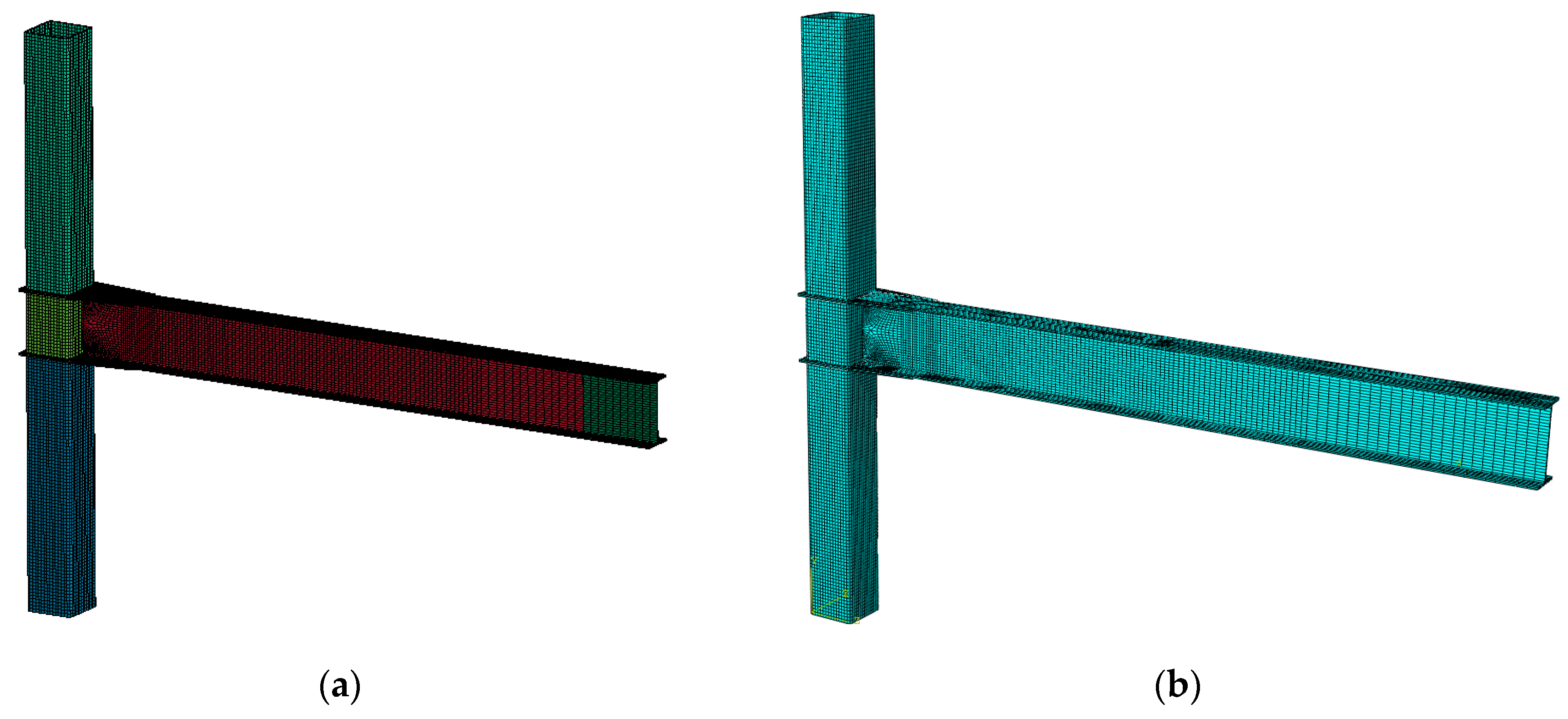
Figure 8.
Moment-drift curves calculated numerically using finite element codes and obtained experimentally by Lee [16] for verification and validation.
Figure 8.
Moment-drift curves calculated numerically using finite element codes and obtained experimentally by Lee [16] for verification and validation.
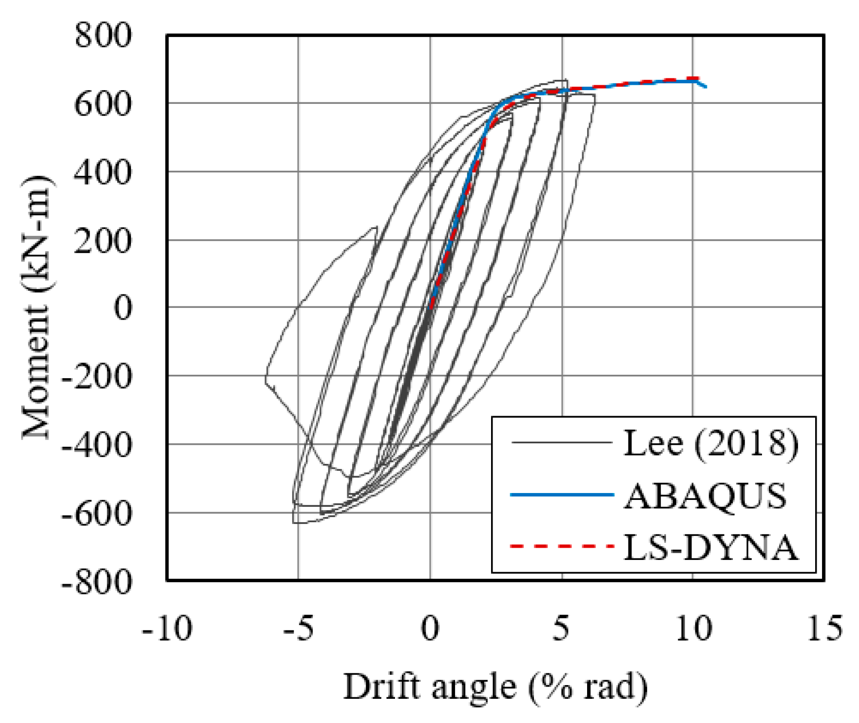
Figure 9.
Comparison between failure modes of test specimen [16], with permission, and maximum principal strain distributions of numerical models at the drift angle of 5.0%. (a) Failure of beam web for test specimen; (b) maximum principal strain distribution on beam web for LS-DYNA model; (c) maximum principal strain distribution on beam web for ABAQUS model; (d) failure of beam flange for test specimen; (e) maximum principal strain distribution on beam flange for LS-DYNA model; (f) maximum principal strain distribution on beam flange for ABAQUS model.
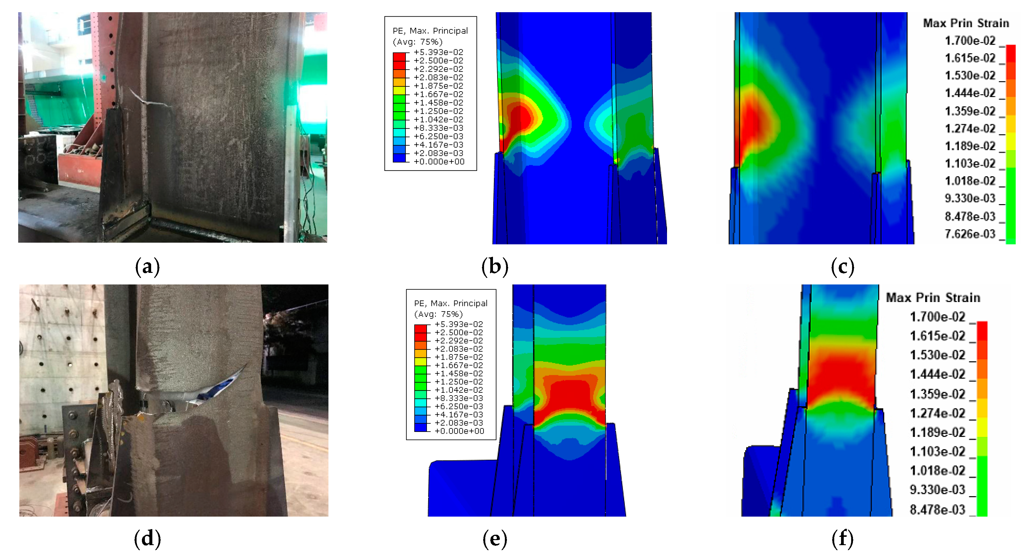
Figure 10.
Finite element models of plate-reinforced large CFT connection. (a) LS-DYNA model; (b) ABAQUS model.
Figure 10.
Finite element models of plate-reinforced large CFT connection. (a) LS-DYNA model; (b) ABAQUS model.
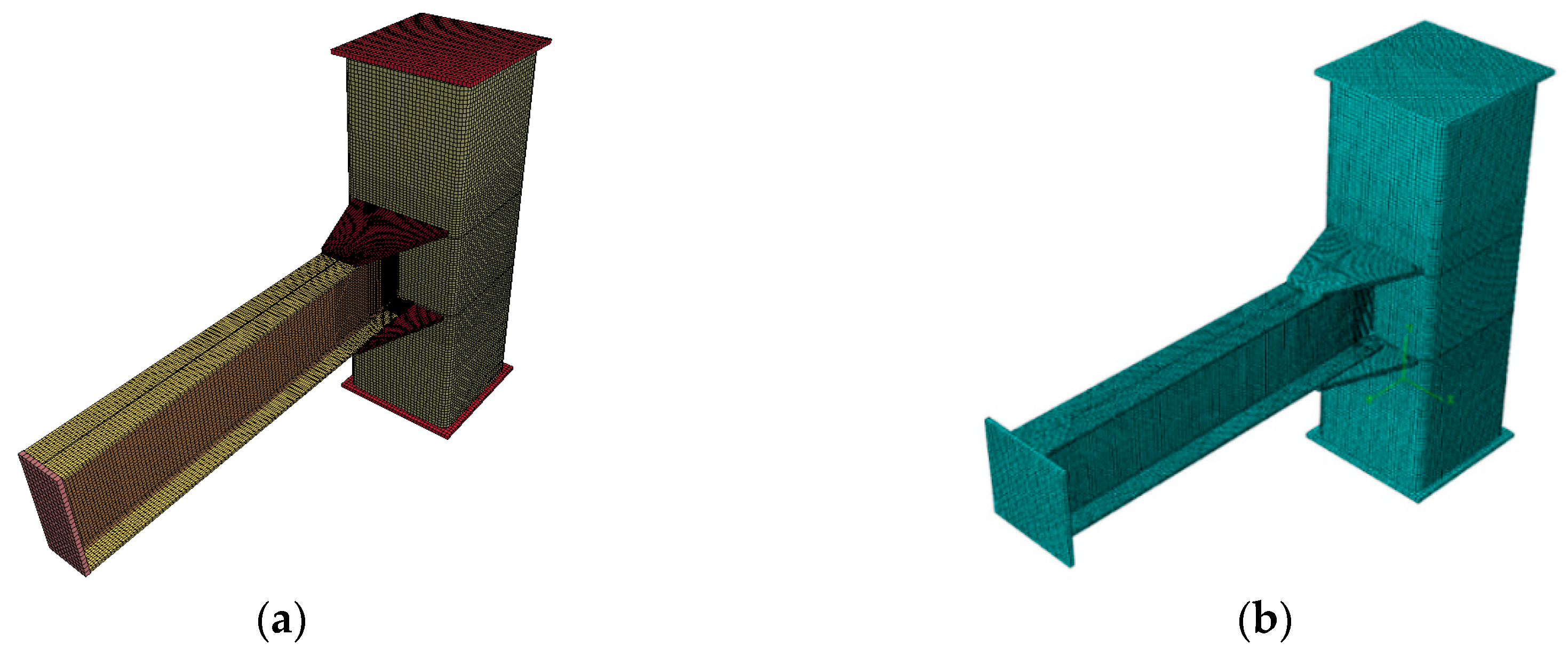
Figure 11.
Normalized moment-drift curves generated by two different finite element codes for the proposed column.
Figure 11.
Normalized moment-drift curves generated by two different finite element codes for the proposed column.
Figure 12.
Simulation results for large CFT connections at t = 20 ms. (a) W = 227 kg; (b) W = 454 kg; (c) W = 1814 kg; (d) W = 4536 kg; (e) W = 11,000 kg.
Figure 12.
Simulation results for large CFT connections at t = 20 ms. (a) W = 227 kg; (b) W = 454 kg; (c) W = 1814 kg; (d) W = 4536 kg; (e) W = 11,000 kg.


Figure 13.
Von Mises stress distribution in the vicinity of connection of numerical models at t = 20 ms. (a) W = 227 kg; (b) W = 454 kg; (c) W = 1814 kg; (d) W = 4536 kg; (e) W = 11,000 kg.
Figure 13.
Von Mises stress distribution in the vicinity of connection of numerical models at t = 20 ms. (a) W = 227 kg; (b) W = 454 kg; (c) W = 1814 kg; (d) W = 4536 kg; (e) W = 11,000 kg.
Figure 14.
Deflection histories of beam and column for through-diaphragm large CFT connection. (a) Beam; (b) column.
Figure 14.
Deflection histories of beam and column for through-diaphragm large CFT connection. (a) Beam; (b) column.

Figure 15.
Deflection histories of beam and column for plate-reinforced large CFT connection. (a) Beam; (b) column.
Figure 15.
Deflection histories of beam and column for plate-reinforced large CFT connection. (a) Beam; (b) column.
Figure 16.
Comparison of end rotation between two different connections. (a) Beam; (b) column.
Figure 17.
Deflection ratio of through-diaphragm to plate-reinforced connection.

Table 1.
Improvised explosive device (IED) standoff distance chart.
| Improvised Explosive Device (IED) | Explosive Mass (kg) (TNT Equivalent) | Building Evacuation Distance (m) | Outdoor Evacuation Distance (m) |
|---|---|---|---|
| Pipe bomb | 2.3 | 21 | 259 |
| Suicide belt | 4.5 | 27 | 330 |
| Suicide vest | 9 | 34 | 415 |
| Briefcase/suitcase bomb | 23 | 46 | 564 |
| Compact sedan | 227 | 98 | 457 |
| Sedan | 454 | 122 | 534 |
| Passenger/cargo van | 1814 | 195 | 838 |
| Small moving van/delivery truck | 4536 | 263 | 1143 |
| Moving van/water truck | 13,608 | 375 | 1982 |
| Semitrailer | 27,216 | 475 | 2134 |
Table 2.
Determination of blast loading.
| Blast Scenario | W (kg) | R (m) | Target | Z (m/kg1/3) |
|---|---|---|---|---|
| 1 | 227 | 6 | Beam | 0.98 |
| 227 | 4 | Column | 0.66 | |
| 2 | 454 | 6 | Beam | 0.78 |
| 454 | 4 | Column | 0.52 | |
| 3 | 1814 | 6 | Beam | 0.49 |
| 1814 | 4 | Column | 0.33 | |
| 4 | 4536 | 6 | Beam | 0.36 |
| 4536 | 4 | Column | 0.24 | |
| 5 | 11,000 | 6 | Beam | 0.25 |
| 11,000 | 4 | Column | 0.18 |
Table 3.
Through-diaphragm large CFT connection.
| W (kg) | Max Deflection (mm) | End Rotation (Degrees) | Evaluation | Failure Mode at t = 20 ms | ||||
|---|---|---|---|---|---|---|---|---|
| Beam | Column | Beam | Column | Beam | Column | Beam | Column | |
| 224 | 27 | 13 | 0.39 | 0.19 | A 1 | A | No damage | No damage |
| 454 | 52 | 23 | 0.74 | 0.33 | A | A | No damage | No damage |
| 1814 | 421 | 95 | 6.01 | 1.36 | NA 1 | A | Significant damage to beam near column face | Minor damage to concrete at bottom |
| 4536 | 1042 | 342 | 14.6 | 4.89 | NA | NA | Separation of beam from column | Entire damage to concrete |
| 11,000 | 2082 | 906 | 27.5 | 12.8 | NA | NA | Separation of beam from column | Entire damage to concrete |
1 A and NA indicate “Accepted” and “Not Acceptable”, respectively, based on design criteria in UFC 3-340-02 [21] for end rotation of the member.
Table 4.
Plate-reinforced large CFT connection.
| W (kg) | Max Deflection (mm) | End Rotation (Degrees) | Evaluation | Failure Mode at t = 20 ms | ||||
|---|---|---|---|---|---|---|---|---|
| Beam | Column | Beam | Column | Beam | Column | Beam | Column | |
| 224 | 26 | 14 | 0.37 | 0.20 | A 1 | A | No damage | No damage |
| 454 | 48 | 24 | 0.69 | 0.34 | A | A | No damage | No damage |
| 1814 | 269 | 93 | 3.85 | 1.33 | NA 1 | A | Minor damage to reinforcing plate | Minor damage to concrete near bottom and connection |
| 4536 | 682 | 328 | 9.68 | 4.69 | NA | NA | Significant damage to beam near column face | Entire damage to concrete |
| 11,000 | 2004 | 923 | 26.6 | 13.0 | NA | NA | Separation of beam from column | Entire damage to concrete |
1 A and NA indicate “Accepted” and “Not Acceptable”, respectively, based on design criteria in UFC 3-340-02 [21] for end rotation of the member.
© 2020 by the authors. Licensee MDPI, Basel, Switzerland. This article is an open access article distributed under the terms and conditions of the Creative Commons Attribution (CC BY) license (http://creativecommons.org/licenses/by/4.0/).
Share and Cite
MDPI and ACS Style
Shin, J.; Hwang, S.-H.; Kim, J. Numerical Investigation of Blast Performance of Plate-Reinforced Moment-Resisting Connection Using Large Concrete Filled Tubular Section. Appl. Sci. 2020, 10, 3700. https://doi.org/10.3390/app10113700
AMA Style
Shin J, Hwang S-H, Kim J. Numerical Investigation of Blast Performance of Plate-Reinforced Moment-Resisting Connection Using Large Concrete Filled Tubular Section. Applied Sciences. 2020; 10(11):3700. https://doi.org/10.3390/app10113700
Chicago/Turabian StyleShin, Jinwon, Seong-Hoon Hwang, and Jinkyu Kim. 2020. "Numerical Investigation of Blast Performance of Plate-Reinforced Moment-Resisting Connection Using Large Concrete Filled Tubular Section" Applied Sciences 10, no. 11: 3700. https://doi.org/10.3390/app10113700
Note that from the first issue of 2016, this journal uses article numbers instead of page numbers. See further details here.