Article

NSHT: New Smart Hybrid Transducer for Structural and Geotechnical Applications

1
Department of Engineering Università degli Studi della Campania “Luigi Vanvitelli” Via Roma 29, 81031 Aversa (CE), Italy
2
HPSYSTEM srl, Via Papini n.12, 80024 San Giorgio a Cremano (NA), Italy
*
Author to whom correspondence should be addressed.
Appl. Sci. 2020, 10(13), 4498; https://doi.org/10.3390/app10134498
Submission received: 4 June 2020 / Revised: 23 June 2020 / Accepted: 25 June 2020 / Published: 29 June 2020
(This article belongs to the Special Issue Computational and Experimental Assessment in Structural Engineering)

Abstract

:

Featured Application

The proposed work provided a structural transducer able to continuously measure the strain on linear structures in time and space. The transducer has been realized connecting fiber-reinforced tapes and optical fiber sensors. It has been possible, then, to overcome some weaknesses of traditional optical fiber sensors, like fragility and critical positioning, in actual civil structures. The system has been tested in some real scale examples and was shown to satisfy the requirements of easy on-site applications. The feasibility of the sensor and the transducer allow for using it in connection with fiber-reinforced tapes as an integrated system for smart structural reinforcement as well those which can be used for the continuous health monitoring of structures consequent to restoration and repair.

Abstract

This work describes the application of a new transducer prototype for continuous monitoring in both the structural and geotechnical fields. The transducer is synthetically constituted by a wire of optical fiber embedded between two fiber tapes (fiberglass or carbon fiber) and glued by a matrix of polyester resin. The fiber optical wire ends have been connected to a control unit whose detection system is based on Brillouin optical time-domain frequency analysis. Three laboratory tests were carried out to evaluate the sensor’s reliability and accuracy. In each experiment, the transducer was applied to a sample of inclinometer casing sets in different configurations and with different constraint conditions. The experimental collected data were compared with theoretical models and with data obtained from the use of different measuring instruments to perform validation and calibration of the transducer at the same time. Several diagrams can compare the transducer and highlight its suitability for the monitoring and maintenance of structures. The characteristic of the transducer suggests its use as a mixed system for reinforcing and monitoring, especially in the lifetime maintenance of critical infrastructures such as transportation and service networks, and historical heritage.

1. Introduction

An increasing number of territories and engineering works are seriously threatened by a combination of adverse effects related to natural disasters (e.g., landslides, earthquakes) or human-made causes (such as traffic-induced vibrations, degradation of structures, absence of maintenance). This problem mainly affects the countries characterized by old infrastructures and old towns of historical, artistic, and cultural interest.
In this context, it becomes essential to develop Early Warning Systems (EWS) to quickly detect potentially dangerous events which occurred in specific areas or on engineering works [1] to define an appropriate intervention strategy consisting of stabilization works or structural reinforcements.
Several studies [2,3,4,5] and analyses exist in the literature that used conventional transducers, among others, for structural and geotechnical EWS or Structural Health Monitoring (SHM).
Generally, such procedures used local sensors such as strain gauges, accelerometers, laser sensors, doppler, and reticles with multicore optical fiber.
Damaged buildings, monuments, cavities, and infrastructures are significantly increasing due to the broader exposed areas to natural hazards and due to the old age of the civil constructions and require a strong effort for their surveillance and maintenance. In this context, it becomes essential to develop innovative Early-Warning Systems (EWS), as well as Structural Health Monitoring and Reinforcement (SHMR), able to detect any anomalous behavior [6,7,8,9,10,11]. These systems contain conventional and unconventional, distributed, and local sensors. These EWSs can collect the information and manage it remotely.
In the following report, two experimental approaches have been described. One concerns the development of a New Hybrid Distributed Transducer to be used both for the detection of landslide movements and for structural monitoring and reinforcement. The second approach consists of the development of a smart system of local sensors based on a wired data acquisition system to collect and analyze structural data from different locations in a structure. The measured data are addressed toward a central acquisition unit that can be interrogated remotely. The approach exploits the variety of low-cost sensors included in a smartphone and a set of libraries of protocols and programming tools (API).
Regarding the first approach, in the laboratories of Department of Engineering of the University of Campania, "Luigi Vanvitelli" distributed strain and temperature measurement devices have been developed using an optical fiber cable for communications as a sensor. The proposed method is based on a technique described in [12]. The acquisition system is based on the device reported in [13]. The system allows for measuring temperature and strain as high as 10 με along with the fiber with a spatial resolution of about 0.8 m at a low frequency (0.1 Hz).
Such a type of distributed strain measurements can be performed in slopes or along with linear infrastructures even over long distances, representing a significant advantage for conventional pointwise strain measurements (topographic measurements, inclinometers, strain gauges, among the others), which can provide only local data, with the risk of missing critical points, [14].
Several applications of optical fiber as strain sensors in the geotechnical field have been performed in recent years. Iten and Puzrin [15] used optical fiber embedded in a natural slope subjected to extremely slow movement to locate the boundaries of the sliding mass. Examples of seepage and strain monitoring systems realized by using optical fiber sensors in embankment dams can be found in [16,17], and other applications are available in geosynthetics and reinforced soil slopes used on artificial and small-scale physical models [18,19].
Optical fibers have also been used for the measurement of soil displacement profiles based on the principle of the inclinometer tube [20,21,22]. The work presented in [23] describes one of the first applications in an embankment slope, ad hoc instrumented with inclinometers with optical fiber sensors glued on. The described set-up shows the suitability of that array of sensors to detect soil strain increasing during rainwater infiltration. However, the cost of such type of monitoring was not competitive, and technical problems due to the instrumentation of the inclinometer’s tubes made this application only a prototype. Moreover, most of these researches were based on the Fiber Bragg Grating (FBG) sensing technique [24,25,26,27,28]: with this method, only small portions of the optical cable constitute the sensors. The FBG sensors connected and glued onto the surface of a plastic rod for measuring bending strains and axial strains give pointwise information along the inclinometer tube. In landslide detection, where often the sliding surface localizes in a very narrow shear band, pointwise measurements can fail to recognize actual soil movements. Consequently, distributed sensing results in a more effective tool.
In [29,30,31], further investigation on landslide monitoring using physical models highlights the difficulties in setting up and analyzing the coupling between the soil and the sensor. Moreover, since the optical fiber sensor is simply embedded into the soil, it is recognized that the strain transfer between the soil and the sensor is not wholly ensured, and also depends on the overburden pressure.
The qualification and surveillance of structures require testing and monitoring that are usually done using pointwise sensors. The acquisition time is limited to the initial lifetime of the structure or at the end of manufacturing. Several analyses for SHMR can be found in the literature based on ultrasonic testing [32,33], thermography [34,35], and measurements of static deformation and dynamic vibrations [36,37]. Moreover, some static stress and dynamic vibration analyses using strain gauges, accelerometers [38] or contactless laser Doppler vibrometers, broadband reflection gratings with multicore optical fiber [39,40,41] are often described. However, many research works suggest that one of the biggest challenges of SHMR is to prevent the sensor from damage [42,43,44]. In this respect, optical fibers for telecommunications, which are the sensing devices when Brillouin Optical Time Domain Analysis (BOTDA) is used, are very robust and do not suffer time or chemical degradation, provided the fiber is adequately protected from mechanical injuries, as it is the case of the sensor proposed here [45,46].
Barrias and Bao describe the evolution of the SHMR with a review of the major experiments and results carried out to date and show the effectiveness of the use of optical fiber sensors [47,48].
Many works describe embedded sensors for different types of structures: reinforced concrete wall, pre-stressed concrete bridge [49], the optical fiber in wind turbine blade [50], integrated optical fiber in functionalized carbon structures (FCS) [51] and also for the detection of vibration, surface cracking and buckling phenomena [52,53,54] in reinforced concrete, pre-stressed concrete (PSC) [55], and post-tensioned PSC [56], where the effectiveness of distributed sensors is highlighted.
In [51], an example of the integration of functionalized carbon structure with optical fiber sensing is reported, but experimental results concerning integrated reinforcement and sensors are not yet present to the authors’ knowledge.
The present paper aims to show a prototype of an improved transducer (New Smart Hybrid Transducer (NSHT)) that can overcome the drawbacks of traditional solutions based on pointwise sensors [57].
At first, one must specify that NSHT is a transducer, which is a complex system of which the sensor is only one of the constituents.
The system allows for the continuous monitoring of engineering works and terrestrial portions, even for lengths of hundreds of meters, while providing information about mechanical deformations and thermal variations.
NSHT can be assembled in implants and safely transported thanks to its design features that also can avoid breaking during transportation and installation, overcoming the drawbacks of existing solutions based on distributed sensors. [58,59,60,61,62,63]
In this paper, we propose two examples of the application of NSHT: the first as a smart inclinometer and the second as a Structural Health Monitoring and Reinforcement device (SHMR). In these two applications, we analyze the accuracy and the reliability of the NSHT transducer using a conventional optical acquisition system.
In this work, the experimental analysis is presented describing the application of NSHT made of a BOTDA optical fiber sensor joined to mechanical support, suited ad hoc designed to fulfill safety and secure handling during installation and lifetime. The proposed experiments consider the effectiveness of the system. Moreover, the correlation between the hard measures and mechanical interpretation of structural behavior is proposed as well. The central aspect here considered is focused on the following point solution:
The connection systems between the sensor and the element under observation do not realize a fully coupled stress transfer, making the strain measurements only qualitative;
The use of glue to fix the fiber on the structural element does not assure the possibility of performing long-time observations, as it is unstable from a thermomechanical point of view and disconnections of the fiber in many points along the element can occur, which reduce the efficiency of the system;
When the sensor must be used in hard environments, such as slopes and rail tracks, where repeated long-time measurements must be done, it is necessary to realize appropriate coating of the fiber to avoid damage;
Monitoring over long distances (in the order of several tens of meters) requires appropriate technical solutions for transporting and assembling the distributed transducer.
In subsequent sections, laboratory tests, results, and discussion of the application of NSHT in a simple beam structure and inclinometer tube are reported.

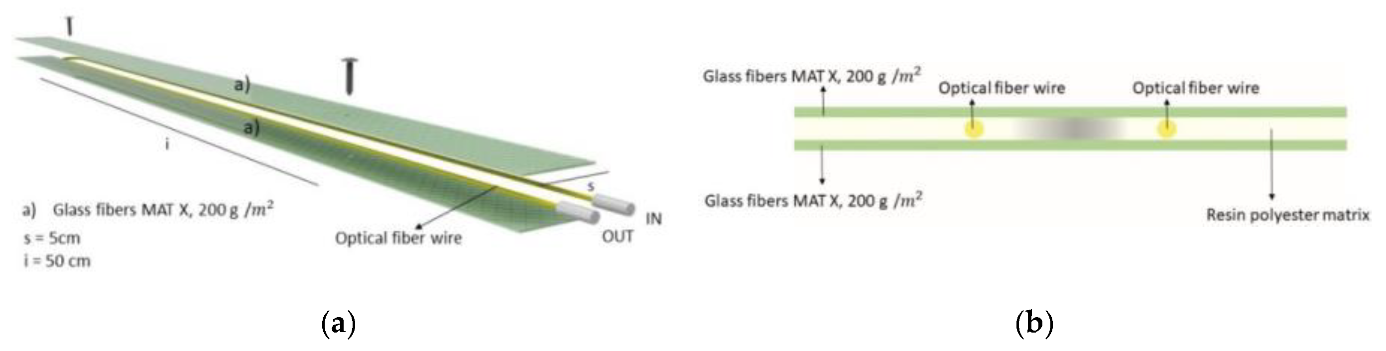
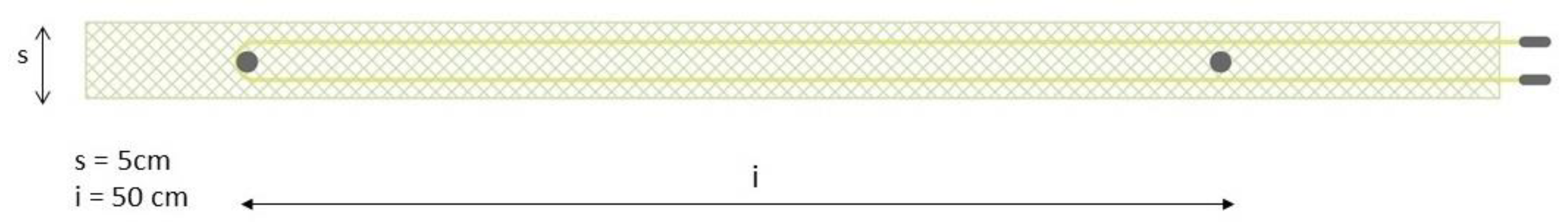
2. Materials and Methods

Three different types of tests were carried out to validate the accuracy and reliability of the transducer measurements. The transducer is synthetically constituted by a wire of optical fiber embedded between two fiber tapes and glued by a matrix of polyester resin. Two kinds of sensors were made, the first merging two glass fiber tapes (GG) (Figure 1) and the second pairing the glass tape with a carbon one (CG) (Figure 2). In Figure 3, top view of the embedded transducer is depicted
The fiber filament runs along with the support with a U-shaped path to determine an Inner segment and an Outer one, whose endpoints were connected to the control unit. There are fastening elements every 50 cm, to ensure perfect adhesion to the substrate. The configurations of the sensors are shown in the pictures below.
This system was applied to the specimen constituted in an inclinometer casing (Cross-section depicted in Figure 4) by a structural glue to ensure the perfect splinting of the elements.
The data acquisition is performed by control units with different levels of accuracy, whose detection system is based on Brillouin optical time-domain frequency analysis (BOTDA).
In the following paragraphs, both the materials used, then the methods of data acquisition, are described.

2.1. First Test: Supported Beam Equipped with GG

The tests aimed to evaluate the accuracy of the transducer by comparing experimental strain measures with the analytical results from beam theory.
The transducer was installed over a specimen that consists of an inclinometer casing. The structural scheme and the mechanical and geometrical properties are reported in Figure 5 and Table 1.
The pipe was equipped with two sensors located at 90 degrees. The experimental set-up is described in Table 2.
During the experiment, the structure was subjected to increasing constrained displacement in the middle span section. The transducer has recorded the strain along with the structure at the following load steps:
  • v = 0 ;
  • v = 2.5   cm ;
  • v = 4.5   cm ;
  • v = 6.5   cm .

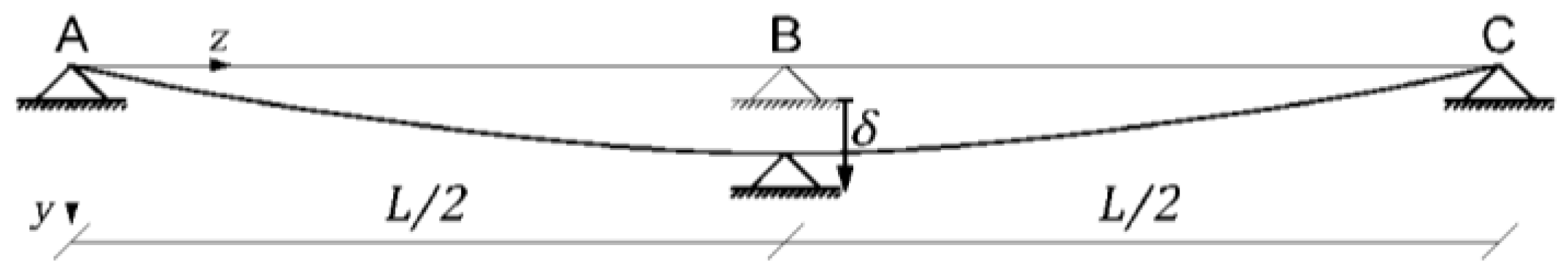
2.2. Experimental Interpretation Through Flexure Beam Theory

In this section, the analytical solution of the bending beam is briefly recalled, and it is used to relate the measured strain with the expected deflection of the structure. The theoretical model of the beam is its axis, i.e., the straight line of the centroids of the cross-sections. The z axis of the reference frame coincides with the beam axis. The beam deforms into a line belonging to the vertical y z plane. The y coordinate of the curved line is the bending displacement v ( z ) .
Starting from the measured strains ε and knowing the aluminum tube radius,   R , it was possible to calculate the beam curvature χ
χ = d φ d s
Recalling that under the Bernoulli’s hypothesis of plane sections that remain perpendicular to the beam’s deformed axis, and the assumption that the displacements are infinitesimal, d s d z , d v d φ d z , one obtains the curvature-displacement linear law
χ = d φ d z = d 2 v d z 2 = ε y
By a first numerical integration of the χ function, one gets the rotation function of the beam ( v i   ( z ) ),
v i ( z ) = ( μ ε i + μ ε i 1 2 R 10 6 ) Δ z i + v i 1 ( z )
where the factor 1 10 6 is the conversion factor from μ ε to ε ;
R = 0.041   m is the radius of the tube-sensor system, given by the sum of the radius of the aluminum tube R 1 = 0.04   m and an estimate of half the sensor radius set equal to R 2 = 0.001   m
Δ z i = z i z i 1
Moreover, by a second numerical integration, one obtains the displacement function
v i ( z ) = ( v i ( z ) + v i 1 ( z ) 2 ) Δ z i + v i 1 ( z )
The integration requires the knowledge of the initial value of displacement and its derivative, which must be evaluated by imposing the following boundary condition:
{ v ( 0 ) = 0 v ( l ) = 0

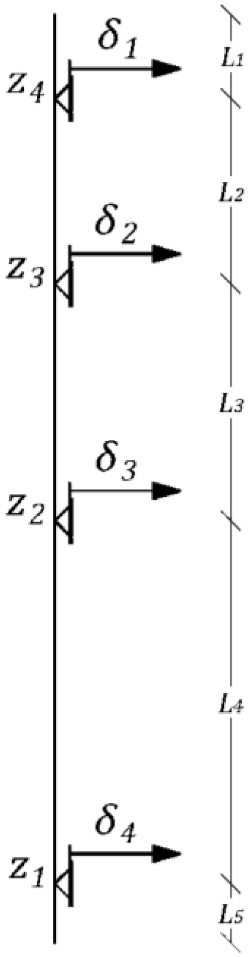
2.3. Second Test: Horizontal Inclinometer Equipped with GG Transducer

The tested specimen consisted of an inclinometer casing tube equipped with standard displacement transducers. The tube (with the same cross-section as the previous experiment) consisted of three segments joined to form the whole cylinder. The three segments were fastened, employing two collars that caused a little disturbance to the alignment of the transducer. The optical fiber-based transducers instrumented the inclinometer casing. The transducer was fastened to the cylinder along its generatrix. Table 3 below reported the geometry data of the structure used for the test and the experimental set-up is described in Table 4.
The GG transducer is made according to the scheme reported in Figure 6. The inclinometer measures, in terms of displacements, have been converted into strains by numerical derivation, then they were compared with the transducer output. The inclinometer, indeed, furnishes displacement measures that must be elaborated in order to convert them into strain by means of derivation with respect to the length coordinate.
The experiment consisted of the application of a constrained displacement at the first end of the structure, while the opposite end was kept clamped; namely, neither displacement nor rotations were allowed. The applied displacement ran from 0 to 0.014 m.

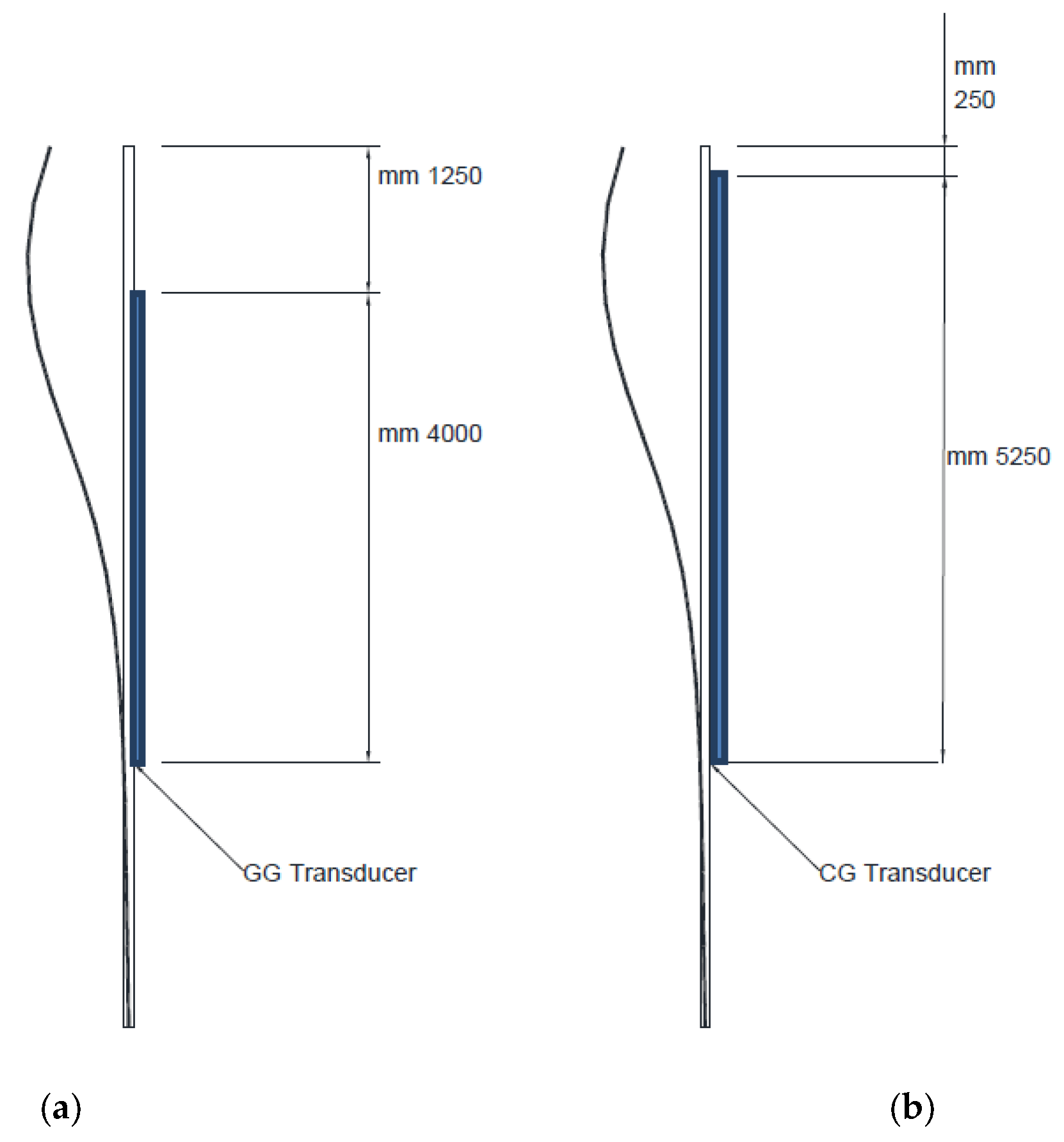
2.4. Third Test: Vertical Inclinometer Equipped with GG and CG Transducer

One of the most critical aspects regarding the evaluation of the experimental results is structural identification. That means determining a numerical model suitable for providing accurate predictions of the behavior of the structural element subjected to specific stresses. The identification of the structural model consists of applying inverse calculation techniques to correlate the test results to the actual stresses or displacements. This approach consists of the identification of mechanical properties, modifying their values appropriately, and minimizing a suitable functional norm of the difference between the experimental results and the expected theoretical ones. Therefore, based on experimental data and reliable information on geometry and materials, it is possible to define a predictive model that represents the behavior of the tested elements.
The third experiment has been designed to apply structural identification techniques to the measured data. To the scope, the inclinometer has been disposed vertically and fixed to support using flexible collars; the structure was subjected to prescribed displacements at some of the supports whilst the remainder was kept fixed. The inclinometer pipe was instrumented with the proposed transducer and with its traditional displacement acquisition system.
Figure 7 represents the structural model of the third experiment. Prescribed displacements acted on the structure. In particular, the displacements δ 1 and δ 2 are the prescribed displacements of magnitude 2.5   cm that were applied to the pipe. The displacements δ 3 δ 4 are unknown, due to the flexibility of the supporting devices. The displacement depended on the fastening devices that evidenced rewardable mobility. The structural identification consisted of finding the minimal difference norm between the measured and calculated strain along the beam. As design variables, we chose, besides the constraint displacements δ i ,   i { 1 , , 4 } , the span measures L 1 ,   L 2 ,   L 3 ,   L 4 ,   L 5 (Figure 7).
The tested specimen was equipped with two kinds of transducers, as shown in Table 5.
The test set-up is represented in Figure 8, where the inclinometer cylinder has been schematically represented as a one-dimensional beam subjected to prescribed boundary displacements.
Like in the previous example, the procedure consists of comparing the strain obtained from displacement measurements via space derivation to the strain measured with the NSHT.
The measured strain using the CG and the GG transducers was acquired according to two different set-ups. The first set-up concerned a CG transducer that was fastened to the cylinder starting at a depth of 250   mm , see Figure 8a. The second set-up is described in Figure 8b. Both experimental set-ups are described in Table 6

3. Results and Discussion

The results of the measurements and calculations obtained from the tests are reported in diagrams in order to make a better comparison both in quantitative and qualitative terms.

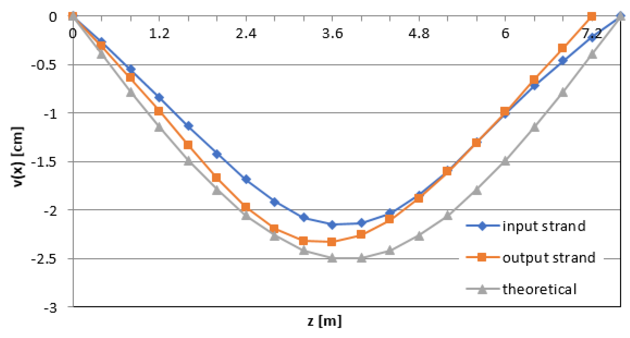
3.1. Test 1: Beam Deflection and Imposed Deformation

As described in the previous section, the experiment concerned a three-supports beam subjected to the central support settlement. The curved line of the beam centroids was calculated by the beam theory, and it was obtained from the experimental results through numerical integration of the curvature, calculated from the measured strain. In the pictures below (Figure 9, Figure 10 and Figure 11), the data comparison related to the 2.5 , 4.5 , and 6.5   cm displacements is shown.
The difference shown in the graph between the measured values and the theoretical model could undoubtedly be attributed to the fact that the theoretical values refer to the axis of the pipe, while the measured ones refer to the fiber positioned at the boundary of the cross-section.

3.2. Test 2: Horizontal Inclinometer Measurement and GG Transducer

In Figure 12, the GG transducer strain measures from NSHT are compared with the strain calculated from the displacement derivative of the inclinometer measurements.
The diagram shows the agreement of the strain measurements from the GG transducer and the calculated strain from the inclinometer measurements. The percentage differences between the two sets showed picks of 20% in correspondence with the metallic collars that fastened the inclinometer pipe. If we considered only smooth points, the average difference percentage was 1%.

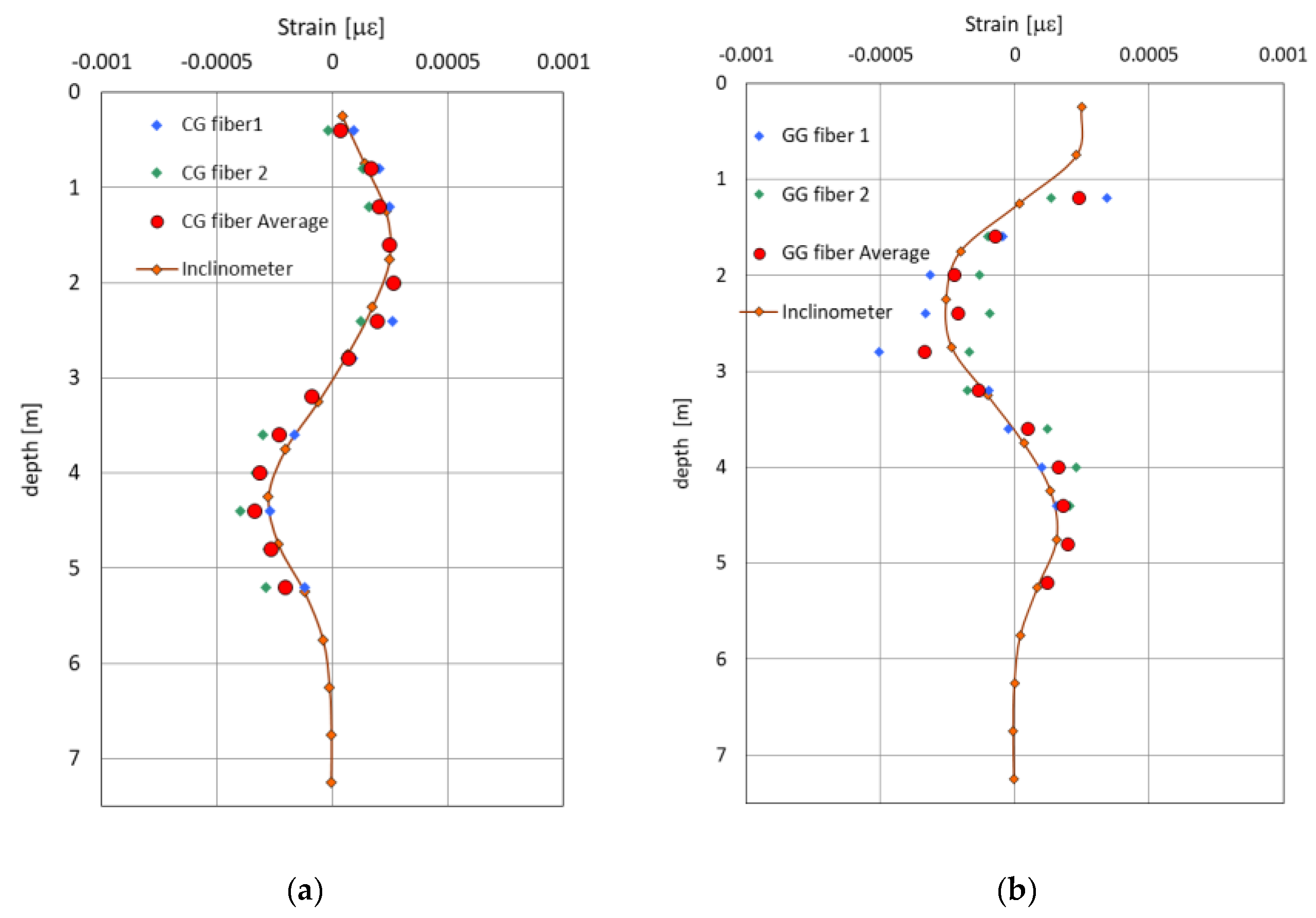
3.3. Test 3: Vertical Inclinometer Measurement and GG and CG Transducers

In the following, Figure 13 shows the comparison of the strain measures obtained using CG and GG transducers with the strain arising from the derivative of the displacement obtained by the inclinometer cylinder. In the figures below, the transducer measures refer to two pickup phases, namely fiber 1 and fiber 2; subsequently, the two measures were averaged, resulting in the fiber average dataset. Furthermore, in the diagram, the strain obtained by the inclinometer displacement measure is drawn as well.
From the comparison of Figure 13, it can be seen that the strain obtained using the CG transducer presents fewer errors due to the quality of the used fiber and the transducer building technique compared to the GG transducer. The GG transducer, indeed, was realized with G.652 fiber that suffers a more significant loss of signal in the presence of relatively high curvatures. The CG transducer was made of G.657 fiber that presents less loss of signal in the presence of curvatures of the fiber. Moreover, the manufacturing process in the case of the GG transducer has suffered some little, but not negligible, localized curvatures of the fiber. Henceforth, the diagrams show recognizing that the CG transducer, equipped with ITU (International Telecommunication Union) G.657 fiber, furnishes a better strain map than the GG transducer equipped with G.652 fiber. The worst result, at the GG transducer, is obtained at a position near to the collar joining the cylinder segments, at a point about 1250   mm from the inclinometer casing top.

4. Conclusions

The present paper showed the feasibility of using optical fiber sensors in the behavior evaluation and monitoring of structures and craftworks; the purpose of the NSHT application is to have feasible and robust continuous measurements of structural stress in time and space. Indeed, the transducer can monitor the strain and, consequently, the stress, directly. The proposed sensor and the techniques used in the experimental activity showed that continuous measures of strain are useful to reconstruct the structure’s displacement. Moreover, the tests directly give the strain and stress measures correlated to the structure’s safety factor. The proposed transducer showed its peculiarities during the application and set-up. Indeed, it does not suffer a hazardous environment due to the coupling to a fiber-resins-based composite. Moreover, it furnished the continuous, in-space strain pattern along with the structure.
The proposed experiment has focused on the inverse method devoted to reconstructing the displacement field upon the strain measures that could evaluate the complete response of the structure under the loading path.
The fitting between theoretical and experimental results showed that the strain measurements are reliable for displacement calculation. The measured strain was revealed to have low error and uncertainty thanks to NSHT. Finally, the proposed sensor allowed the user to read displacements and all related structural information along the axis of the structure instead of the section strain.

Author Contributions

Conceptualization, V.M., L.O., and E.D.; methodology, V.M., L.O., and E.D.; software, V.M., L.O., E.D., P.F., R.Z., L.D.G., M.D.C., M.M., L.E. and E.C.; validation, V.M., A.C., L.O., E.D., P.F., R.Z., L.D.G., M.D.C., and E.C.; formal analysis, V.M., L.O., E.D., P.F., R.Z., L.D.G., M.D.C., and E.C.; investigation, L.E., V.M., L.O., E.D., P.F., R.Z., L.D.G., M.D.C., and E.C.; resources, V.M., L.O., E.D., P.F., R.Z., L.D.G., M.D.C., and E.C.; data curation, V.M., L.O., E.D., P.F., R.Z., L.D.G., M.D.C., and E.C.; writing—original draft preparation, L.E., V.M., L.O., E.D., P.F., R.Z., L.D.G., M.D.C., and E.C.; writing—review and editing, V.M., L.O., E.D., P.F., R.Z., L.D.G., M.D.C., L.E. and E.C.; visualization, V.M., L.O., E.D., P.F., R.Z., L.D.G., M.D.C., and E.C.; supervision, V.M., L.O., and E.D.; project administration, V.M., L.O., and E.D.; funding acquisition, V.M., L.O., and E.D. All authors have read and agreed to the published version of the manuscript.

Funding

This research was funded by the Università degli Studi della Campania “L.Vanvitelli”, grant Programma VALERE: “VAnviteLli pEr la RicErca”, DDG n. 516–24/05/2018.

Conflicts of Interest

The authors declare no conflict of interest.

References

  1. Olivares, L.; Damiano, E.; Netti, N.; de Cristofaro, M. Geothecnical properties of two pyroclastic deposits involved in catastrophic flowslides for implementation in early warning systems. Geosciences 2019, 9, 24. [Google Scholar] [CrossRef] [Green Version]
  2. Liu, B.; Xi, P.; Guo, Y.; Zhang, D. Field test study of soil displacement screw pile using distributed optical fiber based on BOTDA technique. J. Cent. South Univ. 2017, 48, 779–786. [Google Scholar] [CrossRef]
  3. Damiano, E.; Avolio, B.; Minardo, A.; Olivares, L.; Picarelli, L.; Zeni, L. A laboratory study on the use of optical fibers for early detection of pre-failure slope movements in shallow granular soil deposits. Geotech. Test. J. 2017, 40. [Google Scholar] [CrossRef]
  4. Damiano, E.; Greco, R.; Guida, A.; Olivares, L.; Picarelli, L. Investigation on rainwater infiltration into layered shallow covers in pyroclastic soils and its effect on slope stability. Eng. Geol. 2017, 220, 208–218. [Google Scholar] [CrossRef]
  5. Palladino, S.; Esposito, L.; Ferla, P.; Totaro, E.; Zona, R.; Minutolo, V. Experimental and numerical evaluation of residual displacement and ductility in ratcheting and shakedown of an aluminum beam. Appl. Sci. 2020, 10, 3610. [Google Scholar] [CrossRef]
  6. Damiano, E.; Mercogliano, P.; Netti, N.; Olivares, L. A “simulation chain” to define a multidisciplinary decision support system for landslide risk management in pyroclastic soils. Nat. Hazards Earth Syst. Sci. 2012, 12, 989–1008. [Google Scholar] [CrossRef]
  7. Olivares, L.; Damiano, E.; Mercogliano, P.; Picarelli, L.; Netti, N.; Schiano, P.; Savastano, V.; Cotroneo, F.; Manzi, M.P. A simulation chain for early prediction of rainfall-induced landslides. Landslides 2014, 11, 765–777. [Google Scholar] [CrossRef]
  8. Minutolo, V.; Di Ronza, S.; Eramo, C.; Ferla, P.; Palladino, S.; Zona, R. The use of destructive and non-destructive testing in concrete strength assessment for a school building. Int. J. Adv. Res. Eng. Technol. 2019, 10, 252–267. [Google Scholar]
  9. Smarsly, K.; Lehner, K.; Hartmann, D. structural health monitoring based on artificial intelligence techniques. In Congress on Computing in Civil Engineering; ASCE: Pittsburgh, PA, USA, 2007; pp. 111–118. [Google Scholar] [CrossRef]
  10. Minardo, A.; Catalano, E.; Coscetta, A.; Zeni, G.; Zhang, L.; Di Maio, C.; Vassallo, R.; Coviello, R.; Macchia, G.; Picarelli, L.; et al. Distributed fiber optic sensors for the monitoring of a tunnel crossing a landslide. Remote Sens. 2018, 10, 1291. [Google Scholar] [CrossRef] [Green Version]
  11. Chen, X.; Topac, T.; Smith, W.; Ladpli, P.; Liu, C.; Chang, F.-K. Characterization of distributed microfabricated strain gauges on stretchable sensor networks for structural applications. Sensors 2018, 18, 3260. [Google Scholar] [CrossRef] [Green Version]
  12. Allen, R.M. The potential for earthquake early warning in southern california. Science 2003, 300, 786–789. [Google Scholar] [CrossRef] [Green Version]
  13. Bernini, R.; Minardo, A.; Zeni, L. Metodo di ricostruzione del profilo di shift Brillouin in fibra ottica a partire da misure di scattering di Brillouin eseguite nel dominio della frequenza. IT Patent 0,001,408,170, 6 June 2014. [Google Scholar]
  14. Coscetta, A. Apparato per la misura di profilo di shift brillouin in fibra ottica basato sull’acquisizione in tempo reale del segnale differenziale. IT Patent 0,001,422,139, 3 May 2016. [Google Scholar]
  15. Iten, M.; Puzrin, A.M. BOTDA road-embedded strain sensing system for landslide boundary localization. Smart Sens. Phenom. Technol. Netw. Syst. 2009, 7293. [Google Scholar] [CrossRef]
  16. Farhadiroushan, M.; Johansson, S. Seepage and strain monitoring in embankment dams using distributed sensing in optical fibers-theoretical background and experiences from some installations in Sweden. In Proceedings of the International Symposium on Dam Safety and Detection of Hidden Troubles, Xi’an, China, 1–3 November 2005. [Google Scholar]
  17. Gao, P. The application of distributed optical fiber sensing in seepage flow monitoring system. Int. J. Digit. Content Technol. Appl. 2012, 6, 75–181. [Google Scholar]
  18. Lee, K.M.; Manjunath, V.R. Experimental and numerical studies of geosynthetic-reinforced sand slopes loaded with a footing. Can. Geotech. J. 2000, 37, 828–842. [Google Scholar] [CrossRef]
  19. Moser, F.; Lienhart, W.; Woschitz, H.; Schuller, H. Long-term monitoring of reinforced earth structures using distributed fiber optic sensing. J. Civ. Struct. Health Monit. 2016, 6, 321–327. [Google Scholar] [CrossRef] [Green Version]
  20. Pei, H.; Cui, P.; Yin, J.; Zhu, H.; Chen, X.; Pei, L.; Xu, D. Monitoring and warning of landslides and debris flows using an optical fiber sensor technology. J. Mt. Sci. 2011, 8, 728–738. [Google Scholar] [CrossRef]
  21. Zeni, L.; Picarelli, L.; Avolio, B.; Coscetta, A.; Papa, R.; Zeni, G.; Di Maio, C.; Vassallo, R.; Minardo, A. Brillouin optical time-domain analysis for geotechnical monitoring. J. Rock Mech. Geotech. Eng. 2015, 7, 458–462. [Google Scholar] [CrossRef] [Green Version]
  22. Minardo, A.; Damiano, E.; Olivares, L.; Picarelli, L.; Zeni, L.; Avolio, B.; Coscetta, A. Soil Slope Monitoring by Use of A Brillouin Distributed Sensor. In Proceedings of the 2015 Fotonica AEIT Italian Conference on Photonics Technologies, Turin, Italy, 6–8 May 2015; pp. 1–4. [Google Scholar] [CrossRef]
  23. Shi, B.; Sui, H.; Liu, J.; Zhang, D. The BOTDR-Based Distributed Monitoring System for Slope Engineering. In Proceedings of the 10th IAEG International Congress, Nottingham, UK, 6–10 September 2006. [Google Scholar]
  24. Pei, H.; Yin, J.; Zhu, H.; Hong, C. Development and Application of an Optical Fiber Sensor Based In-Place Inclinometer for Geotechnical Monitoring. In Proceedings of the ASCE Geo-Frontiers Congress, Dallas, TX, USA, 13–16 March 2011; Volume 1, pp. 1111–1120. [Google Scholar]
  25. Bao, H.; Dong, X.; Shao, L.-Y.; Zhao, C.-L.; Chan, C.C.; Shum, P. Temperature-insensitive 2-D pendulum clinometer using two fiber bragg gratings. Ieee Photonics Technol. Lett. 2010, 22, 863–865. [Google Scholar] [CrossRef] [Green Version]
  26. Di Ronza, S.; Eramo, C.; Minutolo, V.; Palladino, S.; Totaro, E.; Ferla, P.; Zona, R.; Ronga, T.; Pomicino, C.C. Experimental tests on gully tops and manhole TOPS devices according to EN124 standard. Int. J. Adv. Res. Eng. Technol. 2020, 11, 276–295. [Google Scholar]
  27. Guo, C.; Chen, D.; Shen, C.; Lu, Y.; Liu, H. Optical inclinometer based on a tilted fiber Bragg grating with a fused taper. Opt. Fiber Technol. 2015, 24, 30–33. [Google Scholar] [CrossRef]
  28. Anastasopoulos, D.; Smedt, M.D.; Roeck, G.D.; Vandewalle, L.; Reynders, E.P.B. Damage identification using sub-microstrain fbg data from a pre-stressed concrete beam during progressive damage testing. Proceedings 2018, 2, 462. [Google Scholar] [CrossRef] [Green Version]
  29. Olivares, L.; Damiano, E. Postfailure mechanics of landslides: Laboratory investigation of flowslides in pyroclastic soils. J. Geotech. Geoenviron. Eng. 2007, 133, 51–62. [Google Scholar] [CrossRef]
  30. Schenato, L.; Palmieri, L.; Camporese, M.; Bersan, S.; Cola, S.; Pasuto, A.; Galtarossa, A.; Salandin, P.; Simonini, P. Distributed optical fiber sensing for early detection of shallow landslides triggering. Sci. Rep. 2017, 7, 14686. [Google Scholar] [CrossRef] [PubMed]
  31. Zhu, H.-H.; Shi, B.; Zhang, J.; Yan, J.-F.; Zhang, C.-C. Distributed fiber optic monitoring and stability analysis of a model slope under surcharge loading. J. Mt. Sci. 2014, 11, 979–989. [Google Scholar] [CrossRef]
  32. Katunin, A.; Dragan, K.; Dziendzikowski, M. Damage identification in aircraft composite structures: A case study using various non-destructive testing techniques. Compos. Struct. 2015, 127, 1–9. [Google Scholar] [CrossRef]
  33. Polimeno, U.; Meo, M. Detecting barely visible impact damage detection on aircraft composites structures. Compos. Struct. 2009, 91, 398–402. [Google Scholar]
  34. Avdelidis, N.; Almond, D.; Dobbinson, A.; Hawtin, B.; Ibarra-Castanedo, C.; Maldague, X. Aircraft composites assessment by means of transient thermal NDT. Prog. Aerosp. Sci. 2004, 40, 143–162. [Google Scholar] [CrossRef]
  35. Usamentiaga, R.; Venegas, P.; Guerediaga, J.; Vega, L.; López, I. Automatic detection of impact damage in carbon fiber composites using active thermography. Infrared Phys. Technol. 2013, 58, 36–46. [Google Scholar] [CrossRef]
  36. Trendafilova, I.; Cartmell, M.; Ostachowicz, W. Vibration-based damage detection in an aircraft wing scaled model using principal component analysis and pattern recognition. J. Sound Vib. 2008, 313, 560–566. [Google Scholar] [CrossRef] [Green Version]
  37. Loutas, T.; Panopoulou, A.; Roulias, D.; Kostopoulos, V. Intelligent health monitoring of aerospace composite structures based on dynamic strain measurements. Expert Syst. Appl. 2012, 39, 8412–8422. [Google Scholar] [CrossRef]
  38. Ratcliffe, C.; Heider, D.; Crane, R.; Krauthauser, C.; Yoon, M.K.; Gillespie, J.W. Investigation into the use of low cost MEMS accelerometers for vibration based damage detection. Compos. Struct. 2008, 82, 61–70. [Google Scholar] [CrossRef]
  39. Zou, Y.; Tong, L.; Steven, G. Vibration-based model-dependent damage (delamination) identification and health monitoring for composite structures—A review. J. Sound Vib. 2000, 230, 357–378. [Google Scholar] [CrossRef]
  40. Westbrook, P.S.; Kremp, T.; Feder, K.S.; Ko, W.; Monberg, E.M.; Wu, H.; Simoff, D.A.; Taunay, T.F.; Ortiz, R.M. Continuous multicore optical fiber grating arrays for distributed sensing applications. J. Lightwave Technol. 2017, 35, 1248–1252. [Google Scholar] [CrossRef]
  41. Floris, I.; Sales, S.; Calderón, P.A.; Adam, J.M. Measurement uncertainty of multicore optical fiber sensors used to sense curvature and bending direction. Measurement 2019, 132, 35–46. [Google Scholar] [CrossRef]
  42. Hong, C.-Y.; Yin, J.-H.; Zhang, Y.-F. Deformation monitoring of long GFRP bar soil nails using distributed optical fiber sensing technology. Smart Mater. Struct. 2016, 25, 085044. [Google Scholar] [CrossRef]
  43. Huang, X.; Yang, M.; Feng, L.; Gu, H.; Su, H.; Cui, X.; Cao, W. Crack detection study for hydraulic concrete using PPP-BOTDA. Smart Struct. Syst. 2017, 20, 75–83. [Google Scholar]
  44. Fajkus, M.; Nedoma, J.; Mec, P.; Hrubesova, E.; Martinek, R.; Vasinek, V. Analysis of the highway tunnels monitoring using an optical fiber implemented into primary lining. J. Electr. Eng. 2017, 68, 364–370. [Google Scholar] [CrossRef] [Green Version]
  45. Stern, Y.; London, Y.; Preter, E.; Antman, Y.; Diamandi, H.; Silbiger, M.; Adler, G.; Levenberg, E.; Shalev, D.; Zadok, A. Brillouin optical correlation domain analysis in composite material beams. Sensors 2017, 17, 2266. [Google Scholar] [CrossRef] [Green Version]
  46. Dragic, P.; Ballato, J. A brief review of specialty optical fibers for brillouin-scattering-based distributed sensors. Appl. Sci. 2018, 8, 1996. [Google Scholar] [CrossRef] [Green Version]
  47. Barrias, A.; Casas, J.; Villalba, S. A review of distributed optical fiber sensors for civil engineering applications. Sensors 2016, 16, 748. [Google Scholar] [CrossRef] [PubMed] [Green Version]
  48. Bao, X.; Chen, L. Recent progress in optical fiber sensors based on Brillouin scattering at University of Ottawa. Photonic Sens. 2011, 1, 102–117. [Google Scholar] [CrossRef] [Green Version]
  49. Banerji, P.; Chikermane, S.; Grattan, K.; Tong, S.; Surre, F.; Scott, R. Application of fiber-optic strain sensors for monitoring of a pre-stressed concrete box girder bridge. IEEE Sens. Proc. 2011, 1345–1348. [Google Scholar] [CrossRef]
  50. Coscetta, A.; Minardo, A.; Olivares, L.; Mirabile, M.; Longo, M.; Damiano, M.; Zeni, L. Wind turbine blade monitoring with brillouin-based fiber-optic sensors. J. Sens. 2017, 2017, 1–5. [Google Scholar] [CrossRef]
  51. Bremer, K.; Weigand, F.; Zheng, Y.; Alwis, L.; Helbig, R.; Roth, B. Structural health monitoring using textile reinforcement structures with integrated optical fiber sensors. Sensors 2017, 17, 345. [Google Scholar] [CrossRef] [PubMed] [Green Version]
  52. Rodríguez, G.; Casas, J.R.; Villaba, S. Cracking assessment in concrete structures by distributed optical fiber. Smart Mater. Struct. 2015, 24, 035005. [Google Scholar] [CrossRef] [Green Version]
  53. Wang, Y.; Jin, B.; Wang, Y.; Wang, D.; Liu, X.; Dong, Q. Distributed fiber-optic vibration detection system. In Proceedings of the 13th International Conference on Ubiquitous Robots and Ambient Intelligence (URAI), Xian, China, 19–22 August 2016. [Google Scholar]
  54. Ruocco, E.; Minutolo, V. Buckling analysis of mindlin plates under the green–lagrange strain hypothesis. Int. J. Struct. Stab. Dyn. 2015, 15, 1450079. [Google Scholar] [CrossRef]
  55. Uva, G.; Porco, F.; Fiore, A.; Porco, G. Structural monitoring using fiber optic sensors of a pre-stressed concrete viaduct during construction phases. Case Stud. Nondestruct. Test. Eval. 2014, 2, 27–37. [Google Scholar] [CrossRef] [Green Version]
  56. Glišić, B.; Hubbell, D.; Sigurdardottir, D.H.; Yao, Y. Damage detection and characterization using long-gauge and distributed fiber optic sensors. Opt. Eng. 2013, 52, 087101. [Google Scholar] [CrossRef]
  57. Coscetta, A.; Damiano, E.; De Cristofaro, M.; Di Gennaro, L.; Esposito, L.; Ferla, P.; Giarusso, G.A.; Iavazzo, L.; Minutolo, V.; Mirabile, M.; et al. An integrated structural and geotechnical early-warning system for deep-seated landslides. 2020; Unpublished Work. [Google Scholar]
  58. Minutolo, V.; Ruocco, E.; Zeni, L. Strain measure in laboratory experiments on concrete beams by means of optical fiber sensors. AIMETA 2017. In Proceedings of the 23rd Conference of the Italian Association of Theoretical and Applied Mechanics, Salento, Italy, 4–7 September 2017; Volume 4, pp. 472–479. [Google Scholar]
  59. Bernini, R.; Minardo, A.; Ciaramella, S.; Minutolo, V.; Zeni, L. Distributed strain measurement along a concrete beam via stimulated brillouin scattering in optical fibers. Int. J. Geophys. 2011, 5. [Google Scholar] [CrossRef] [Green Version]
  60. Bernini, R.; Fraldi, M.; Minardo, A.; Minutolo, V.; Nunziante, L.; Zeni, L. Identification of defects and strain error estimation for bending steel beams using time-domain Brillouin distributed optical fiber sensors. Smart Mater. Struct. 2006, 15, 612–622. [Google Scholar] [CrossRef]
  61. Bernini, R.; Fraldi, M.; Minardo, A.; Minutolo, V.; Nunziante, L.; Zeni, L. Damage detection in bending beams through Brillouin distributed optic-fiber sensor. Bridge Struct. 2005, 1, 355–363. [Google Scholar] [CrossRef]
  62. Zhu, C.; Chen, Y.; Zhuang, Y.; Tang, F.; Huang, J. An embeddable strain sensor with 30 nano-strain resolution based on optical interferometry. Inventions 2018, 3, 20. [Google Scholar] [CrossRef] [Green Version]
  63. Gu, L.; Zhang, L.; Bao, X.; Zhang, M.; Zhang, C.; Dong, Y. Detection of thermal strain in steel rails with BOTDA. Appl. Sci. 2018, 8, 2013. [Google Scholar] [CrossRef] [Green Version]
Figure 1. Glass fiber tapes (GG) Transducer (a) axonometric view, (b) cross-section.
Applsci 10 04498 g001
Figure 2. CG Transducer (a) axonometric view, (b) cross-section.
Applsci 10 04498 g002
Figure 3. Transducer top view.
Applsci 10 04498 g003
Figure 4. Cross-section of inclinometer casing.
Applsci 10 04498 g004
Figure 5. First test–structural scheme.
Applsci 10 04498 g005
Figure 6. Second test: Structural scheme.
Applsci 10 04498 g006
Figure 7. Third test: structural identification.
Applsci 10 04498 g007
Figure 8. Layouts of vertical inclinometer: (a) GG transducer side, (b) CG transducer side.
Applsci 10 04498 g008
Figure 9. Centerline deformation imposed at 2.5 cm.
Applsci 10 04498 g009
Figure 10. Centerline deformation imposed at 4.5 cm.
Applsci 10 04498 g010
Figure 11. Centerline deformation imposed at 6.5 cm.
Applsci 10 04498 g011
Figure 12. Strain diagram GG transducer.
Applsci 10 04498 g012
Figure 13. Experiment 3 strain diagram: (a) CG transducer, (b) GG transducer.
Applsci 10 04498 g013
Table 1. First test: Geometrical parameters.
Length [mm]Radius [mm]Thickness [mm]Inertia [cm4]
760080356.4871
Table 2. First test: Specimen parameters.
TypeStructural GlueFiberLength [mm]Optical FiberResinControl UnitResolution [mm]
GGADEKIT 140 by Axon (bi-component epoxy resin)Glass–Glass7400G.657 single-mode optical fibersPOLIPLAST M608 M11 R OPTO SENSING 400
Table 3. Second test: geometrical parameters.
Length [mm]Radius [mm]Thickness [mm]Inertia [cm4]
750080356.4871
Table 4. Second test: transducer parameters.
TypeStructural GlueFiberLength [mm]Optical FiberResinControl UnitResolution [mm]
GGADEKIT 140 by Axon (bi-component epoxy resin)Glass–Glass
(mat220 fiberglass polyester composite)
6500G.652 single-mode optical fibersBIRESIN® CR80
(AXSON)
OPTO SENSING50
Table 5. Third test–geometrical parameters.
Length [mm]Radius [mm]Thickness [mm]Inertia [cm4]
760080356.4871
Table 6. Third test: specimen parameters.
TypeStructural GlueFiberLength [mm]Optical FiberResinControl UnitResolution [mm]
GGADEKIT 140 by AxonGlass–Glass
(mat220 fiberglass polyester)
4000G.652 single-mode optical fibersBIRESIN® CR80
(AXSON)
OPTO SENSING OSD-1"400
CGADEKIT 140 by AxonCarbon–Glass
(biaxial 200 carbon fiber composite and two mat100 fiberglass polyester composite)
5250G.657 single-mode optical fibersBIRESIN® CR80
(AXSON)
OPTO SENSING OSD-1"400

