Structural Optimization of Slotting Nozzle Used to Improve Coal-Seam Permeability
by
Zhaolong Ge
1,2, 
Jianyu Zhong
1,2,
Jianguo Zhang
3,4,*,
Yingwei Wang
3,4,
Youchang Lvu
3,4 and
Sai Zhang
1,2 1
State Key Laboratory of Coal Mine Disaster Dynamics and Control, Chongqing University, Chongqing 400044, China
2
School of Resources and Safety Engineering, Chongqing University, Chongqing 400044, China
3
State Key Laboratory of Coking Coal Exploitation and Comprehensive Utilization, Pingdingshan 467000, China
4
Pingdingshan Tianan Coal. Mining Co., Ltd., Pingdingshan 467000, China
*
Author to whom correspondence should be addressed.
Appl. Sci. 2020, 10(2), 699; https://doi.org/10.3390/app10020699
Submission received: 17 December 2019
/
Revised: 9 January 2020
/
Accepted: 15 January 2020
/
Published: 19 January 2020
Abstract
:Slotting directional hydraulic fracturing is a new method for improving permeability of a coal seam in underground coal mines that can solve problems related to non-uniform permeability enhancement in the seam. A slotting nozzle is the key to this technology: its performance determines the length and stability of the slotted hole. In this study, computational fluid dynamics was used to study the effects of stable segment length L, convergent angle θ, and straight segment length l on the performance of slotting nozzles. The results showed that the order of parameters affecting nozzle performance is: θ > L > l. When the total length of the slotting nozzle was fixed, the dynamic pressure gradually decreased with an increase of L and the rate of decrease slowed down. With an increase of θ, dynamic pressure increased quadratically and the rate of change gradually decreased. With an increase of l, the dynamic pressure decreased quadratically and the rate of change gradually increased. A slotting nozzle (L = 0 mm, θ = 30°, l = 9 mm) was manufactured and measurements of flow coefficient, water jet morphology, and a slotting experiment were carried out. The experimental results showed that the flow coefficient, water jet convergence, and slotting depth of the optimized slotting nozzle were obviously higher than those of the original design, which proved the validity of using this numerical method to optimize the slotting nozzle structure.
1. Introduction
Coalbed methane (CBM) is a green resource with high energy efficiency. Extraction of CBM not only increases energy supply, but can also reduce greenhouse gas emissions and the occurrence of gas disasters. China is rich in CBM resources, ranking third in the world [1], but is highly dependent on natural gas imports. In 2018, China became the world’s largest importer of natural gas, with an import volume of 125.4 billion m3 [2,3,4]. CBM occurrence conditions in China are complex, mainly due to three factors: (i) low gas saturation, with an average gas content of 45%; (ii) low reservoir pressure, with a pressure coefficient of generally less than 0.8; and (iii) high degree of coal-seam metamorphism [5]. Therefore, CBM is mainly exploited by underground extraction in China. CBM reservoir permeability in China is extremely low (10−4–10−3 mD), which is three to four orders of magnitude lower than that in Australia and the United States [6]. Therefore, improving coal-seam permeability and increasing underground extraction of CBM has become a focus of research.
Methods that have been employed to increase the permeability of coal seams include dense boreholes, deep-hole blasting, hydraulic flushing, hydraulic slotting, and hydraulic fracturing [7,8,9,10]; however, these technologies have drawbacks. In particular, the range of coal-seam permeability enhancement is small and uneven, and the construction cost is high. To solve these problems, some scholars have proposed the use of slotting directional hydraulic fracturing (SDHF), which combines hydraulic slotting with hydraulic fracturing [11,12,13]. The principle of this method is connecting a coal-seam slotting device with a high-pressure sealing drill rod. Water is forced into the slotting device through the drill rod by a pump and the water forms a high-speed jet after acceleration through the slotting nozzle; the slotting device simultaneously moves slowly into the borehole. In this way, coal around the borehole will be slotted and a regular slotted hole will be formed [14]. After hydraulic slotting, the slotted hole is sealed and then connected to a high-pressure pump for hydraulic fracturing. Hence, the exposed area, coal-seam structure ratio, and permeability are increased. The gas flow conditions are improved and the gas extraction rate will increase. Use of this technology significantly decreases the number of drill rods required and shortens the time required for gas pre-drainage.
Ge found that the size of the slotted hole is the key parameter affecting slotting–directional hydraulic fracturing (SDHF) [4]. The design of the slotting nozzle can enhance the water jet and its structure will significantly affect its ability to slot the coal seam [15]. To improve the effectiveness of slotting, much research into optimized structures has been undertaken, based on various conditions [16,17,18,19,20,21]. Nikonov first proposed a conical straight slotting nozzle structure [22]. Due to its high energy-transfer efficiency and simple manufacture, this nozzle has been widely used in mining, petroleum, fire, and other industries. Some scholars have found that streamlined inner-surface slotting nozzles designed on the basis of hydrodynamic theory have high energy-transfer efficiency. Li used a simple conical slotting nozzle to study the cavitation of a water jet [23]. The results showed that the slotting nozzle can intensify the shear between the water jet and the surrounding liquid, resulting in a large amount of cavitation. The Rankin–Shape water jet slotting nozzle manufactured by Aqua-Dyne (USA) can maintain convergence and high efficiency of the water jet for a larger target distance [24]. Liu studied the influence of slotting nozzle shape on the water jet flow coefficient and flow field [25]. Vijay analyzed the influence of throat length of a convergent–expansion slotting nozzle on the flow-field parameters, both theoretically and experimentally [26]. The slotting nozzle used in coal-seam slotting is, however, quite different from common slotting nozzles, especially with respect to limited slotting nozzle length and the sudden change of channel direction. The performance of slotting nozzles designed by existing experience is unsatisfactory, which seriously restricts application of this technology.
To design a slotting nozzle suitable for SDHF in coal mines, we used computational fluid dynamics (CFD) to study the effects of stable segment length L, convergent angle θ, and straight segment length l on the performance of a slotting nozzle using an orthogonal test. The slotting nozzle structure was optimized according to the performance. The optimized slotting nozzle was then used for flow measurements and slotting experiments, and compared with the existing slotting nozzle design to verify the validity of using this numerical method to optimize its structure.
2. Structural Optimization of Slotting Nozzle Design
2.1. Structural Parameters Affecting Performance of Slotting Nozzle
A conical straight slotting nozzle is most commonly used in coal-seam hydraulic slotting, as shown in Figure 1. Due to its special working environment, the total length of the slotting nozzle is limited, and its special runner structure needs selection of different structural parameters from those of a conventional nozzle. The structure of a slotting nozzle comprises total length L0, outlet diameter D, stable segment length L, convergent angle θ, and straight segment length l.
According to calculations using a 75 mm drill pipe commonly used in coal mines, the maximum length of the slotting nozzle is 26 mm. At present, the rating of high-pressure pumps commonly used in coal mines is 31.5 MPa, the flow rate is 200 L/min, and so the diameter of the slotting nozzle outlet was determined to be 3 mm. Hence, the three factors that affect the performance of slotting nozzle are stable segment length L, convergent angle θ, and straight segment length l. Reasonable values of these three factors will influence the slotting ability.
2.2. Design of Slotting Nozzle Structural Parameters Orthogonal Optimization
Orthogonal design is a scientific method used to select a suitable number of representative experimental points from a large number of experimental points according to the principle of mathematical statistics, and to rationally arrange multi-factor experiments using a standardized “orthogonal table”. The above analysis showed that the performance of a slotting nozzle is mainly related to stable segment length L, convergent angle θ, and straight segment length l. Each factor was considered at four levels in the appropriate ranges for these three factors. According to the selected model of three factors and four levels, an orthogonal table was selected to include sixteen numerical experiments, as shown in Table 1.
A slotting nozzle suitable for coal-seam slotting conditions requires not only good convergence of the water jet, but also higher velocity and striking force of the jet for the same target distance. The striking force of a water jet on a target is directly related to its dynamic pressure (pk). The dynamic pressure of a water jet is proportional to the jet velocity, so we used dynamic pressure as the evaluation index. The performances of 16 different types of slotting nozzles were compared by investigating the water jet dynamic pressure under the same working pressure: specifically, the axial dynamic pressure (pk1) and longitudinal profile dynamic pressure (pk2) of the water jet were evaluated at a distance of 150 mm from the slotting nozzle outlet.
2.3. Numerical Experiments to Optimize Slotting Nozzle Index
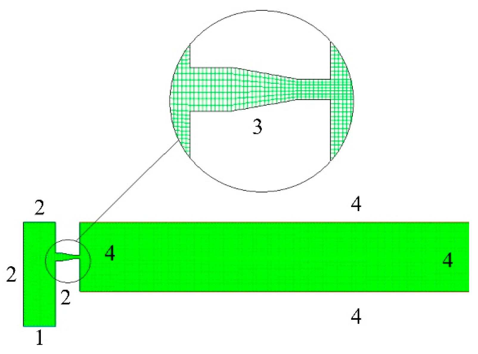
Numerical simulation of the performances of the slotting nozzles was carried out using CFD modeling. Each slotting nozzle was installed vertically on the slotting device, within which there was high-speed turbulent flow. The control equation therefore comprised equations of continuity, the Navier–Stokes equation, and realizable k–ε equations. The geometric model was relatively small; therefore, quadrilateral mesh generation was used to generate the meshes of the inner and outer flow fields. The grid spacing was 0.5 mm. The geometric model of the slotting nozzle flow field is shown in Figure 2.
The finite-volume method was used to disperse the control equation; simple algorithms were used to couple the pressure and velocity. The fluid was assumed to be ideal, that is, the flow was steady, and gravity and cavitation were not be taken into consideration. The boundary conditions are shown in Table 2.
In the process of optimizing the slotting nozzle structural parameters, a submerged water jet was used to simulate the inner and outer flow fields. Since the submerged water jet had the characteristics of fast attenuation, using a smaller model to simulate the slotting nozzle outflow could clearly distinguish the advantages and disadvantages of the structure and save calculation time. The numerical simulation results of Experiment 1 are shown in Figure 3.
Figure 3 shows that the high-pressure water underwent acceleration inside the slotting nozzle, and the dynamic pressure gradually increased in this section; however, the dynamic pressure on the section did not change uniformly. In particular, in the area between the bend of the flow channel and the convergent section, the distribution of the slotting dynamic pressure was greatly influenced by the structure of the flow channel. At the turning point of the main channel of the slotting device into the slotting nozzle, the dynamic pressure distribution was larger in the upper part of the nozzle axis, but smaller in the lower part. When high-pressure water entered the stable section of the slotting nozzle, the distribution of dynamic pressure was high in the middle and low on both sides of the same cross-section. An obvious low-pressure zone formed near the inner wall of the slotting nozzle. The non-uniform distribution of the dynamic pressure inside the slotting nozzle created conditions for the generation of vortices and flow recirculation. The formation of a large number of vortices and recirculation greatly reduce the quality of the water jet.
Based on simulated data of internal and external flow fields of sixteen different slotting nozzles, the axial and longitudinal dynamic pressure curves of the water jet at a distance of 150 mm from the slotting nozzle outlet were plotted, as shown in Figure 4.
The curves of Figure 4a show that with an increase of the abscissa, the dynamic pressure gradually decreased and its rate of change gradually decreased. Slotting nozzles with different structural parameters had different outlet dynamic pressures for the same pressure source. The type 0-30-9 slotting nozzle (stable segment length L = 0 mm, convergent angle θ = 30°, and straight segment length l = 9 mm) had the best performance. Not only was the outlet dynamic pressure larger than those of other slotting nozzles, but the attenuation of the axial pressure was slower. Slotting nozzle type 9-10-12 had the worst performance. Figure 4b presents longitudinal profiles of the dynamic pressures of the sixteen different types of slotting nozzles at a distance of 150 mm from the slotting nozzle outlet under submerged conditions. The maximum dynamic pressure at the slotting nozzle axis gradually decreased with increase of the distance from the axis to both sides, and the rate of change gradually decreased. Slotting nozzles with different structural parameters had different dynamic pressures at the outlet of the slotting nozzle under the same pressure source: the difference was most obvious at the axis. The above optimization results showed that the slotting nozzle with structural parameters of 0-30-9 had the best performance.
2.4. Numerical Experiment Results and Discussion
The performance of a slotting nozzle is mainly related to stable segment length L, convergent angle θ, and straight segment length l. To evaluate the influence of each parameter on its performance and to provide a basis for the processing accuracy of each parameter, the significance of each parameter was analyzed. The results are shown in Table 3.
As seen from Table 3, the convergent angle θ had the largest range; the ranges of the stable segment length L and straight segment length l were similar. The data show that the convergent angle θ had the greatest influence on slotting nozzle performance, while the influences of stable segment length L and straight segment length l were small. According to the magnitude of range, the primary and secondary orders of parameters affecting nozzle performance are: nozzle convergent angle θ > stable segment length L > straight segment length l.
Taking the influencing factors as the abscissa and the water jet pressure at a distance of 150 mm from the outlet as the ordinate, the trends of slotting nozzle structure parameters and performance were plotted, as shown in Figure 5.
When the total length of the slotting nozzle was fixed, the dynamic pressure gradually decreased and the rate of decrease slowed down with an increase of the length of the stable section L. With an increase of convergent angle θ, the dynamic pressure increased quadratically and the rate of change gradually decreased. With an increase of straight segment length l, the dynamic pressure decreased quadratically and the rate of change gradually increased.
3. Materials and Methods
Since numerical simulation simplifies many practical problems in a calculation process, physical experiments were carried out to compare the performance of the optimized slotting nozzle with the original slotting nozzle to verify the optimization results. The main components of the experiment were determination of the flow coefficient and slotting tests. The structural parameters of the original and optimized slotting nozzles are shown in Table 4.
3.1. Experimental System and Equipment
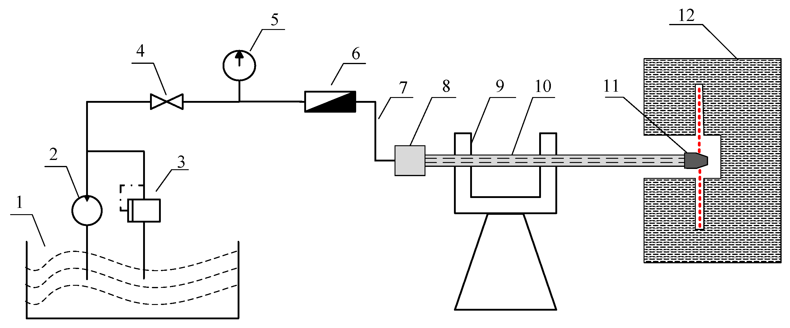
The experimental system consisted of two parts: a flow-coefficient test system and a hydraulic slotting system. A diagram of the system is shown in Figure 6. Real-time monitoring of pressure and flow were achieved with an accuracy of 0.1 MPa and 0.1 mL/min, respectively, using a data-processing system. The water-injection system comprised a plunger pump with a maximum pressure of 31.5 MPa and a maximum flow of 200 L/min.
In the slotting experiment, the slotted material was concrete. The mass ratio of cement, river sand, and stone in the concrete was 1:4:4. Its average uniaxial compressive strength was 6.13 MPa, as determined by uniaxial testing. Specimens are shown in Figure 7.
The flow coefficient of a slotting nozzle represents its energy-transfer efficiency: a higher value indicates better performance. In this experiment, a seismic pressure gauge was used, and the influence of density on the flow coefficient was considered. The formula for calculating the flow coefficient is as follows:
where Q is flow rate, m3/s; A0 is slotting nozzle section area, m2; ρ is water density, kg/m3; ΔP is the pressure difference between two sections of slotting nozzle, MPa.
To minimize reading errors, three flowmeter readings were repeatedly recorded once the pressure and flow of the system were stable. Test data recording and flow-coefficient calculations are shown in Table 5. The results show that the flow coefficient of the optimized slotting nozzle was higher than that of the original slotting nozzle. The optimized structure was, therefore, more conducive to the passage of fluid.
3.2. Experimental Design and Procedures
For the same working conditions, the outlet water jet slotting depth of a slotting nozzle is a key factor to evaluate its real working performance. In this study, the slotting capacities of the original and optimized slotting nozzles were compared. The experimental specimens were poured with concrete. The size of the test box was 1 m3 and water was used as the jet. The experimental procedures were as follows:
- (1)
- The high-pressure pipeline connection was completed and the slotting device was pushed to the appropriate position in the test box;
- (2)
- The test box was closed, the pipeline connection checked, and the pump switched on;
- (3)
- When the pump was stable, the pressure rose rapidly to 28 MPa and measurement of elapsed time was started;
- (4)
- Every 60 s, the pump was rapidly switched off, the water jet slotting depth was measured, and the characteristics of the slots were photographed and recorded; and
- (5)
- Steps (1)–(4) were repeated until the specimen was penetrated or the slotting depth no longer increased with slotting time.
3.3. Results and Discussion
To fully compare the performances of the original and optimized slotting nozzles, the water jet shape, and slotting depth were studied. The results are shown in Figure 8.
Figure 8a provides an intuitive comparison of the original and optimized slotting nozzles at a distance of 600 mm from the nozzle. The photographs were taken at a fixed angle. It is obvious that convergence of the optimized slotting nozzle jet was better than that of the original. Figure 8b compares the slotting results of the two nozzles. It is obvious that the slotting depth of the optimized slotting nozzle was better. The relationships between slot depths and time are shown in Figure 9.
Figure 9 shows that the slotting depth rapidly increased from 0 to 2 min; from 2 to 8 min, the slotting depth increased slowly; after 8 min, the slotting depth hardly changed further. The slotting depth of the optimized slotting nozzle was 1.64 times that of the original slotting nozzle, confirming that the optimized slotting nozzle had higher slotting ability.
4. Conclusions
- (1)
- CFD was used to study effects of stable segment length L, convergent angle θ, and straight segment length l on the performance of slotting nozzles using orthogonal testing. The results showed that the order of parameters affecting nozzle performance is: nozzle convergent angle θ > stable segment length L > straight segment length l.
- (2)
- When the total length of the slotting nozzle was fixed, the dynamic pressure gradually decreased and the rate of decrease slowed down with an increase in the length of the stable section L. With an increase of convergent angle θ, the dynamic pressure increased quadratically and the rate of change gradually decreased. With an increase of straight segment length l, the dynamic pressure decreased quadratically and the rate of change gradually increased.
- (3)
- When the total length of the slotting nozzle was 18 mm, the stable segment length L = 0 mm, convergent angle θ = 30°, and straight segment length l = 9 mm, the slotting nozzle gave the best slotting performance. This design (L = 0 mm, θ = 30°, l = 9 mm) was manufactured and the flow-coefficient measurement, water jet morphology observation, and slotting experiments were carried out. The experimental results showed that the flow coefficient, water jet convergence, and slotting depth of the optimized slotting nozzle were obviously higher than those of the original nozzle, which proved the validity of using this numerical method to optimize the slotting nozzle structure.
Author Contributions
Z.G., J.Z. (Jianyu Zhong), J.Z. (Jianguo Zhang), and Y.W. contributed to the numerical simulation, design of the experiments, analysis of the results, and writing the paper. Y.L. and S.Z. performed the experiments. All authors have read and agreed to the published version of the manuscript.
Funding
This work was supported by the National Natural Science Foundation of China (grant numbers 51504046, 51774055, and 51625401).
Acknowledgments
We thank Kathryn Sole, from Liwen Bianji, Edanz Group China (www.liwenbianji.cn/ac), for editing the English text of a draft of this manuscript.
Conflicts of Interest
The authors declare no conflict of interest.
List of Symbols
| D | Diameter of slotting nozzle outlet |
| L0 | Total length of slotting nozzle |
| L | Stable segment length of slotting nozzle |
| θ | Convergent angle of slotting nozzle |
| l | Straight segment length of slotting nozzle |
| pk | Dynamic pressure of water jet |
| pk1 | Axial dynamic pressure of water jet |
| pk2 | Longitudinal profile dynamic pressure of water jet |
| Q | Flow rate |
| A0 | Slotting nozzle section area |
| ρ | Water density |
| ΔP | Pressure difference between two sections of slotting nozzle |
| d | Slotting depth |
References
- Lu, Y.Y.; Xiao, S.Q.; Ge, Z.L.; Zhou, Z.; Ling, Y.F.; Wang, L. Experimental study on rock-breaking performance of water jets generated by self-rotatory bit and rock failure mechanism. Powder Technol. 2019, 346, 203–216. [Google Scholar] [CrossRef]
- Li, L.G.; Wang, H.Y.; Liu, H. Natural gas fueling the world’s future: A brief summary. In Proceedings of the 27th World Gas Conference (WGC), Natural Gas Industry, Washington, DC, USA, 25–29 June 2018; Volume 38, pp. 1–9. [Google Scholar]
- Guo, W.; Pan, J.P. Mid-term evaluation and prospect of the implementation of the 13th Five-Year Plan for the national oil and gas resources exploration and mining plan. Nat. Gas Ind. 2019, 39, 111–117. [Google Scholar]
- Ge, Z.L.; Zhong, J.Y.; Lu, Y.Y.; Cheng, L.; Zheng, J.W.; Zhou, Z.; Cheng, Y.G. Directional distance prediction model of slotting-directional hydraulic fracturing (SDHF) for coalbed methane (CBM) extraction. J. Pet. Sci. Eng. 2019, 183, 106429. [Google Scholar] [CrossRef]
- Li, Q.; Lu, Y.Y.; Ge, Z.L.; Zhou, Z.; Zheng, J.W.; Xiao, S.Q. A new tree-type fracturing method for stimulating coal seam gas reservoirs. Energies 2017, 10, 1388. [Google Scholar] [CrossRef] [Green Version]
- Lu, Y.Y.; Zuo, S.J.; Ge, Z.L.; Xiao, S.Q.; Cheng, Y.G. Experimental study of crack initiation and extension induced by hydraulic fracturing in a tree-type borehole array. Energies 2016, 9, 514. [Google Scholar] [CrossRef]
- Lu, T.K.; Yu, H.; Zhou, T.Y.; Mao, J.S.; Guo, B.H. Improvement of methane drainage in high gassy coal seam using waterjet technique. Int. J. Coal Geol. 2009, 79, 40–48. [Google Scholar] [CrossRef]
- Chao, M.U.; Wang, H.L.; Huang, W.Y.; Kuang, C.J. Increasing permeability mechanism using directional cumulative blasting in coal seams with high concentration of gas and low permeability. Rock Soil Mech. 2013, 9, 2496–2500. [Google Scholar]
- Kong, X.G.; Wang, E.Y.; Liu, X.F.; Li, N.; Liang Chen, L.; Feng, J.J.; Kong, B.; Li, D.X.; Liu, Q.L. Coupled analysis about multi-factors to the effective influence radius of hydraulic flushing: Application of response surface methodology. J. Gas. Sci. Eng. 2016, 32, 538–548. [Google Scholar] [CrossRef]
- Zhang, Z.B.; Li, X. Numerical study on the formation of shear fracture network. Energies 2016, 9, 299. [Google Scholar] [CrossRef] [Green Version]
- Deng, J.Q.; Lin, C.; Yang, Q.; Liu, Y.R.; Tao, Z.F.; Duan, H.F. Investigation of directional hydraulic fracturing based on true tri-axial experiment and finite element modeling. Comput. Geotech. 2016, 75, 28–47. [Google Scholar] [CrossRef]
- Mao, R.B.; Feng, Z.J.; Liu, Z.H.; Zhao, Y.S. Laboratory hydraulic fracturing test on large-scale pre-cracked granite specimens. J. Nat. Gas Sci. Eng. 2017, 44, 278–286. [Google Scholar] [CrossRef]
- Cheng, Y.G.; Lu, Y.Y.; Ge, Z.L.; Cheng, L.; Zheng, J.W.; Zhang, W.F. Experimental study on crack propagation control and mechanism analysis of directional hydraulic fracturing. Fuel 2018, 218, 316–324. [Google Scholar] [CrossRef]
- Lu, Y.Y.; Ge, Z.L.; Li, X.H.; Chen, J.F.; Liu, Y. Investigation of a self-excited pulsed water jet for rock cross-cutting to uncover coal. J. China Univ. Min. Technol. 2010, 39, 55–58. [Google Scholar]
- Zou, Q.L.; Li, Q.G.; Liu, T.; Li, X.L.; Liang, Y.P. Peak strength property of the pre-cracked similar material: Implications for the application of hydraulic slotting in ECBM. J. Nat. Gas Sci. Eng. 2017, 37, 106–115. [Google Scholar] [CrossRef]
- Quinn, W.R.; Militzer, J. Effects of nonparallel exit flow on round turbulent free jets. Int. J. Heat Fluid Flow 1989, 10, 139–145. [Google Scholar] [CrossRef]
- Yang, G.Y.; Choi, M.S.; Lee, J.S. An experimental study of slot jet impingement cooling on concave surface: Effects of nozzle configuration and curvature. Int. J. Heat Mass Transf. 1999, 42, 2199–2209. [Google Scholar] [CrossRef]
- Guo, S.; Hu, J.; Luo, L.; Xu, Z.S.; Yao, Z. Analysis of assist gas glow and the structural optimizing. Appl. Laser 2007, 27, 403–407. [Google Scholar]
- Zhao, Y.P.; Lu, Y.Y.; Ge, Z.L.; Zuo, W.Q. Study on optimal design of abrasive water jet nozzle used in gas mining. Fluid Mach. 2010, 38. [Google Scholar]
- Ding, X.Q. Abrasive waterjet nozzle structural design and optimization. Modul. Mach. Tool Autom. Manuf. Tech. 2016, 11, 115–118. [Google Scholar]
- Gao, Q.; Zhou, M.; Zhu, L.L. Flow field analysis and structure optimization of FDM 3D printer nozzle. Modul. Mach. Tool Autom. Manuf. Tech. 2018, 11, 34–47. [Google Scholar]
- Nikonov, G.P.; Kuzmich, I.A.; Garbuz, G.D. Hydraulic Coal or Ore Mining Optimal Output Determination-Uses Shield with Slots for Time Based Jets onto Rock Giving Measurable Breakout Volume Craters. International Patent No. SU305266-A, 25 October 1978. [Google Scholar]
- Li, W.K. Research on the Influence of Structure Parameters of Self-Excited Cavitation Jet Nozzle. Bachelor’s Thesis, Shandong University, Shandong, China, 2015. [Google Scholar]
- Xue, S.X. High pressure water jet technology and application. China Saf. Sci. J. 1999, 9, 92. [Google Scholar]
- Liu, D.D.; Feng, Z.H.; Tan, B.H. Numerical simulation and analysis for the flow field of the main nozzle in an air-jet loom based on fluent. Appl. Mech. Mater. 2012, 105–107, 172–175. [Google Scholar] [CrossRef]
- Vijay, M.M.; Zou, C.; Hu, S.G.; Remisz, J.; Tavoularis, S. A Study of the practicality of cavitating water jets. In Jet Cutting Technology; Fluid Mechanics and Its Applications; Lichtarowicz, A., Ed.; Springer: Dordrecht, The Netherlands, 1992; Volume 13. [Google Scholar]
Figure 1.
Conventional slotting nozzle structure.

Figure 2.
Geometric model of slotting nozzle flow field: 1 is the pressure inlet; 2 and 3 are boundary walls; 4 is the pressure outlet.
Figure 2.
Geometric model of slotting nozzle flow field: 1 is the pressure inlet; 2 and 3 are boundary walls; 4 is the pressure outlet.

Figure 3.
(a) Velocity and (b) dynamic pressure distributions of slotting nozzle in submerged condition, (a,b) have the same model scale.
Figure 3.
(a) Velocity and (b) dynamic pressure distributions of slotting nozzle in submerged condition, (a,b) have the same model scale.

Figure 4.
(a) Attenuation curves of water jet dynamic pressures (pk1) along slotting nozzle axis for different types of slotting nozzle; and (b) distribution of water jet dynamic pressures (pk2) along longitudinal profile for different types of slotting nozzle.
Figure 4.
(a) Attenuation curves of water jet dynamic pressures (pk1) along slotting nozzle axis for different types of slotting nozzle; and (b) distribution of water jet dynamic pressures (pk2) along longitudinal profile for different types of slotting nozzle.

Figure 5.
Relationships between dynamic pressure and (a) length of the stable section L, (b) convergent angle θ, and (c) straight segment length l.
Figure 5.
Relationships between dynamic pressure and (a) length of the stable section L, (b) convergent angle θ, and (c) straight segment length l.

Figure 6.
Diagram of experimental system device. 1: Water tank; 2: emulsion pump; 3: relief valve; 4: treading cutoff value; 5: pressure gauge; 6: flow meter; 7: high-pressure water pipe; 8: sealing drill pipe; 9: drilling rig; 10: sealing drilling rod; 11: slotting device; 12: experimental box.
Figure 6.
Diagram of experimental system device. 1: Water tank; 2: emulsion pump; 3: relief valve; 4: treading cutoff value; 5: pressure gauge; 6: flow meter; 7: high-pressure water pipe; 8: sealing drill pipe; 9: drilling rig; 10: sealing drilling rod; 11: slotting device; 12: experimental box.

Figure 7.
Specimens for uniaxial compressive strength testing.

Figure 8.
(a) Contrast of water jet structures of original and optimized slotting nozzles; and (b) experimental slotting results.
Figure 8.
(a) Contrast of water jet structures of original and optimized slotting nozzles; and (b) experimental slotting results.

Figure 9.
Change in slotting depth d with time.


Table 1.
Slotting nozzle structural parameters orthogonal optimization table L16 (43).
| Experiment Number | Stable Segment Length L (mm) | Convergent Angle θ (°) | Straight Segment Length l (mm) |
|---|---|---|---|
| 1 | 0 | 10 | 3 |
| 2 | 0 | 20 | 6 |
| 3 | 0 | 30 | 9 |
| 4 | 0 | 40 | 12 |
| 5 | 3 | 10 | 6 |
| 6 | 3 | 20 | 3 |
| 7 | 3 | 30 | 12 |
| 8 | 3 | 40 | 9 |
| 9 | 6 | 10 | 9 |
| 10 | 6 | 20 | 12 |
| 11 | 6 | 30 | 3 |
| 12 | 6 | 40 | 6 |
| 13 | 9 | 10 | 12 |
| 14 | 9 | 20 | 9 |
| 15 | 9 | 30 | 6 |
| 16 | 9 | 40 | 3 |
Table 2.
Numerical experiment boundary conditions.
| Inlet Pressure | 28 MPa |
|---|---|
| Inlet turbulence intensity | 10% |
| Inlet flow diameter | 23 mm |
| Outlet pressure | 1 atm |
| Outlet turbulence intensity | 10% |
| Outlet flow diameter | 3 mm |
Table 3.
Extreme difference analysis of orthogonal optimization of slotting nozzle structural parameters.
Table 3.
Extreme difference analysis of orthogonal optimization of slotting nozzle structural parameters.
| Experiment Number | Stable Segment Length L (mm) | Convergent Angle θ (°) | Straight Segment Length l (mm) | Dynamic Pressure pk2 (MPa) |
|---|---|---|---|---|
| 1 | 0 | 10 | 3 | 5.04 |
| 2 | 0 | 20 | 6 | 5.29 |
| 3 | 0 | 30 | 9 | 5.39 |
| 4 | 0 | 40 | 12 | 5.33 |
| 5 | 3 | 10 | 6 | 4.79 |
| 6 | 3 | 20 | 3 | 5.11 |
| 7 | 3 | 30 | 12 | 5.04 |
| 8 | 3 | 40 | 9 | 5.30 |
| 9 | 6 | 10 | 9 | 4.45 |
| 10 | 6 | 20 | 12 | 4.64 |
| 11 | 6 | 30 | 3 | 5.28 |
| 12 | 6 | 40 | 6 | 5.24 |
| 13 | 9 | 10 | 12 | 3.90 |
| 14 | 9 | 20 | 9 | 4.58 |
| 15 | 9 | 30 | 6 | 5.04 |
| 16 | 9 | 40 | 3 | 5.34 |
| Mean Value 1 | 5.626 | 4.545 | 5.192 | - |
| Mean Value 2 | 5.060 | 4.905 | 5.090 | - |
| Mean Value 3 | 4.902 | 5.188 | 4.930 | - |
| Mean Value 4 | 4.715 | 5.303 | 4.728 | - |
| Range | 0.547 | 0.758 | 0.464 | - |
Table 4.
Structural parameters of original and optimized slotting nozzles.
| Slotting Nozzle | Stable Segment Length L (mm) | Convergent Angle θ (°) | Straight Segment Length l (mm) |
|---|---|---|---|
| Original slotting nozzle | 5 | 13 | 6 |
| Optimized slotting nozzle | 0 | 30 | 9 |
Table 5.
Flow-coefficient testing conditions and results.
| Slotting Nozzle | Experiment Number | Q (L/min) | Pressure Difference | Flow Coefficient | |
|---|---|---|---|---|---|
| Calculated Value | Average Value | ||||
| Original slotting nozzle | 1 | 88.2 | 28.0 | 0.8857 | 0.8897 |
| 2 | 89.1 | 28.0 | 0.8948 | ||
| 3 | 88.5 | 28.0 | 0.8884 | ||
| Optimized slotting nozzle | 1 | 87.9 | 28.0 | 0.8824 | 0.8958 |
| 2 | 89.7 | 28.0 | 0.9005 | ||
| 3 | 90.1 | 28.0 | 0.9045 | ||
© 2020 by the authors. Licensee MDPI, Basel, Switzerland. This article is an open access article distributed under the terms and conditions of the Creative Commons Attribution (CC BY) license (http://creativecommons.org/licenses/by/4.0/).
Share and Cite
MDPI and ACS Style
Ge, Z.; Zhong, J.; Zhang, J.; Wang, Y.; Lvu, Y.; Zhang, S. Structural Optimization of Slotting Nozzle Used to Improve Coal-Seam Permeability. Appl. Sci. 2020, 10, 699. https://doi.org/10.3390/app10020699
AMA Style
Ge Z, Zhong J, Zhang J, Wang Y, Lvu Y, Zhang S. Structural Optimization of Slotting Nozzle Used to Improve Coal-Seam Permeability. Applied Sciences. 2020; 10(2):699. https://doi.org/10.3390/app10020699
Chicago/Turabian StyleGe, Zhaolong, Jianyu Zhong, Jianguo Zhang, Yingwei Wang, Youchang Lvu, and Sai Zhang. 2020. "Structural Optimization of Slotting Nozzle Used to Improve Coal-Seam Permeability" Applied Sciences 10, no. 2: 699. https://doi.org/10.3390/app10020699
Note that from the first issue of 2016, this journal uses article numbers instead of page numbers. See further details here.