Article

Effect of Thermal Boundary Condition on Tilting Pad Journal Bearing Behavior

1
School of Mechanical Engineering, Pusan National University, Busan 46241, Korea
2
Daegu Research Center for Medical Devices and Rehabilitation, Korea Institute of Machinery and Materials, Daegu 42994, Korea
3
Department of Mechanical Engineering, Korea Polytechnic University, 237. Sangidaehak-ro, Siheung-si, Gyeonggi-do 15073, Korea
*
Author to whom correspondence should be addressed.
Appl. Sci. 2020, 10(21), 7540; https://doi.org/10.3390/app10217540
Submission received: 30 August 2020 / Revised: 22 October 2020 / Accepted: 23 October 2020 / Published: 26 October 2020
(This article belongs to the Section Mechanical Engineering)

Abstract

:

Featured Application

Turbomachinery, lubrication, compressor, pump, turbines.

Abstract

This research presents the effect of the thermal boundary condition on the tilting pad journal bearing characteristics. The thermal boundary condition includes the temperature around the bearing pad, spinning journal, and lubricant supply temperature. Change in bearing performance according to the temperature around each element constituting the bearing was analyzed without paying attention to how the actual thermal boundary conditions around the bearing are configured. High fidelity numerical model of tilting pad journal bearing is presented for (1) the analysis of heat generation in the thin film, (2) heat transfer in the lubricant, (3) heat flux flowing into the journal and pad, (4) temperature change in the journal and bearing, (5) the resultant thermal deformation, (6) change in the lubricant film thickness arising from the thermal deformation of journal and bearing pads, and (7) the resulting change in the heat generation in the thin film. To reach the steady state of the bearing–journal system, the Runge–Kutta scheme with adaptive time step is adopted where the dynamic and thermal system are solved simultaneously in multi-physics model. Performance change of the bearing according to three changes: (a) boundary temperature around shaft, (b) boundary temperature around bearing pads, and (c) lubricant supply temperature were investigated.

1. Introduction

The performance and temperature prediction of bearings supporting the load of rotating machinery is one of the important analysis requirements from the viewpoint of verifying the operational reliability of turbomachinery. Recently, due to the demand for high efficiency and light weight for turbomachinery, the heat generation problem of bearings is often a critical issue. Various studies have been attempted to predict the temperature of the bearing system based on the high-performance computers and commercial software. There have been many researches to predict the bearing performance with numerical approaches. Knight and Niewiarowski [1] presented a journal bearing model for the analysis of the fluid film thermal characteristics in the cavitated region. Taniguchi et al. [2] presented a three-dimensional (3D) thermo-hydrodynamic (THD) lubrication model of tilting pad journal bearing (TPJB) for the steam turbine. Knight and Ghadimi [3] described the cavitation regime and temperature distribution of the pad surface. Kim et al. [4] presented a finite-element (FE)-model-based two-dimensional (2D) TPJB model with a thermo-elasto-hydrodynamic (TEHD) lubrication model. The varying viscosity Reynolds equation and energy equation were coupled via temperature-dependent viscosity relation.
Kim et al. [5] presented a TEHD-lubrication-approach-based TPJB numerical model with modal reduction technique. Gadangi and Palazzolo [6] presented a transient response of TPJB considering thermal effects and the resultant thermal deformation of bearing structure. Desbordes et al. [7] presented 3D FE pad model to perform a time transient analysis of journal bearing system with the pad elastic deformation. Fillon et al. [8] presented effects of the thermal-elastic deformation of bearing pads on the TPJB dynamic behavior. Gadangi et al. [9] presented the bearing thermal effects on the dynamic response under the sudden unbalance status such as blade loss. Monmousseau and Fillon [10] calculated a transient response of TPJB with TEHD lubrication model with a dynamic loading condition. Nassab and Moayeri [11] performed a computational fluid dynamic (CFD) analysis of an axially grooved journal bearing with a thermo-hydrodynamic lubrication model. 3D Navier–Stokes equation coupled via the energy equation is adopted to solve for the bearing pressure and fluid film temperature. Nicholas [12] discussed a TPJB design to reduce the system temperature. Fatu et al. [13] presented a TEHD lubrication model for the analysis of journal bearings under the time varying loading condition. The finite element (FE) model was used for solving the Reynolds equation, thermal deformation, and elastic deformation of the bearing pads. Brito et al. [14] presented the experimental results of the effects of oil supply temperature and pressure on the journal bearing performance. Liu et al. [15] developed the direct solution method of the varying viscosity Reynolds equation. Fluid film pressure and the cavitation boundary could be determined without iteration scheme. They developed a simplified one-dimensional (1D) thermal approach based on the 2D numerical model. Bang et al. [16] performed an experimental work to compare leading edge groove TPJB with conventional journal bearings under different running conditions. Thorat et al. [17] measured the bearing metal temperatures of TPJB with the configuration of five-pad and load-between-pad (LBP). Temperature was measured at the two loaded bottom pads and thermal behavior was predicted by TEHD lubrication model. Tschoepe and Childs [18] measured a hot and cold clearance at test rig. From 16% to 25%, decreased bearing clearance was measured at a hot temperature condition compared to room temperature. Thermal expansion of journal and bearing were measured and predicted. Suh and Palazzolo [19,20] presented a high-fidelity TPJB numerical model with a TEHD lubrication model. Both elastic and thermal deformation of bearing pad were predicted by 3D FE model adopting nonlinear transient dynamic analysis. Hertzian contact theory was used to predict the pivot elastic deformation. Chang [21] predicted the journal bearing performance with the consideration of thermal and cavitation effect using CFD approach with fluid structure interaction (FSI) model, and the predictions were compared with the published results of other researchers. Mo et al. [22] predicted a journal bearing temperature using ANSYS Fluent. Nichols et al. [23] studied the effects of supply flow rate of lubricant on bearing static and dynamics characteristics at steady state condition. Bouyer et al. [24] studied the effects of geometrical defects of a two-lobe journal bearing on system temperature. Bouyer and Fillon [25] performed an experimental test to study the misalignment effect on plain journal bearing performance. Pressure, oil temperature, oil flow rate, and minimum film thickness were measured at various misalignment conditions. El-Butch and Ashour [26] studied the performance of a misaligned TPJB under unsteady loading condition, adopting a TEHD lubrication model. Both elastic and thermal deformations of bearing pads were considered, and a film thickness equation was newly developed to take the misaligned condition into account.
Suh and Choi [27] developed a 3D FE model of TPJB to study the angular misalignment effect. FE node-based film thickness equation was developed. Minimum film thickness, pad thermal deformation, bearing performance, and lubricant peak temperature were simulated with varying amount of misalignment. Yang et al. [28] performed an experimental test and studied the effect of high-temperature inlet oil on the TPJB characteristics. Oil film thickness, temperature rise, and the rotor dynamic behavior under different inlet temperature were tested and compared. Abdollahi and San Andrés [29] studied bearing side leakage flow and utilized an empirical coefficient to provide the efficient bearing oil feeding configuration. Yang and Palazzolo [30,31] presented a full 3D computation numerical model of TPJB with the consideration of multiphase flow, turbulence effects, and thermal expansion of the spinning journal and bearing pads using a two-way FSI model. Detailed comparisons between the CFD and the Reynolds approach were performed. They accurately analyzed the phenomenon of lubricant mixing between pads and entering the pads using 3D CFD technique, but it is limited in application to the actual bearing design due to excessive analysis resources. Conti et al. [32] presented a 3D TPJB model based on the commercial multi-physics software COMSOL. Their research was oriented to the rotordynamic behavior of the bearing–rotor system. On the other hand, there have been other approaches to overcome the bearing performance adopting the active control unit in the journal bearing system [33,34].
In addition to the references mentioned above, a number of numerical analysis models for bearings have been developed so far. However, there have been no in-depth studies related to the performance change according to the change of the thermal boundary conditions of the bearing–journal system. This is due to the difficulty in modeling the heat transfer of bearing pads and journals and predicting the resulting thermal deformation. The axial thermal boundary condition of the journal cannot be taken into account with the 2D bearing model that has been presented in the earliest studies. In addition, it is difficult to predict the exact performance of bearings with the simplified bearing model suggested by most researchers. The following is a summary of the reasons why the numerical approach developed by various researchers to date has had difficulty in considering precise temperature boundary conditions.
(a)
Difficulty in modeling heat transfer between a spinning journal and an oil film (boundary A, Figure 1a)
(b)
Difficulty in modeling heat transfer between oil film–bearing pads (boundary B, Figure 1a)
(c)
Difficult to consider the axial thermal boundary condition of the shaft. In conventional 2D bearing model, it is impossible. (boundary C, Figure 1b)
(d)
Difficult to calculate the film thickness due to thermal deformation of the journal and bearing pads (Figure 1b)
(e)
Difficulties in multi-physics modeling of bearing systems to simultaneously consider bearing dynamics, lubrication, and heat transfer/heat distortion problems
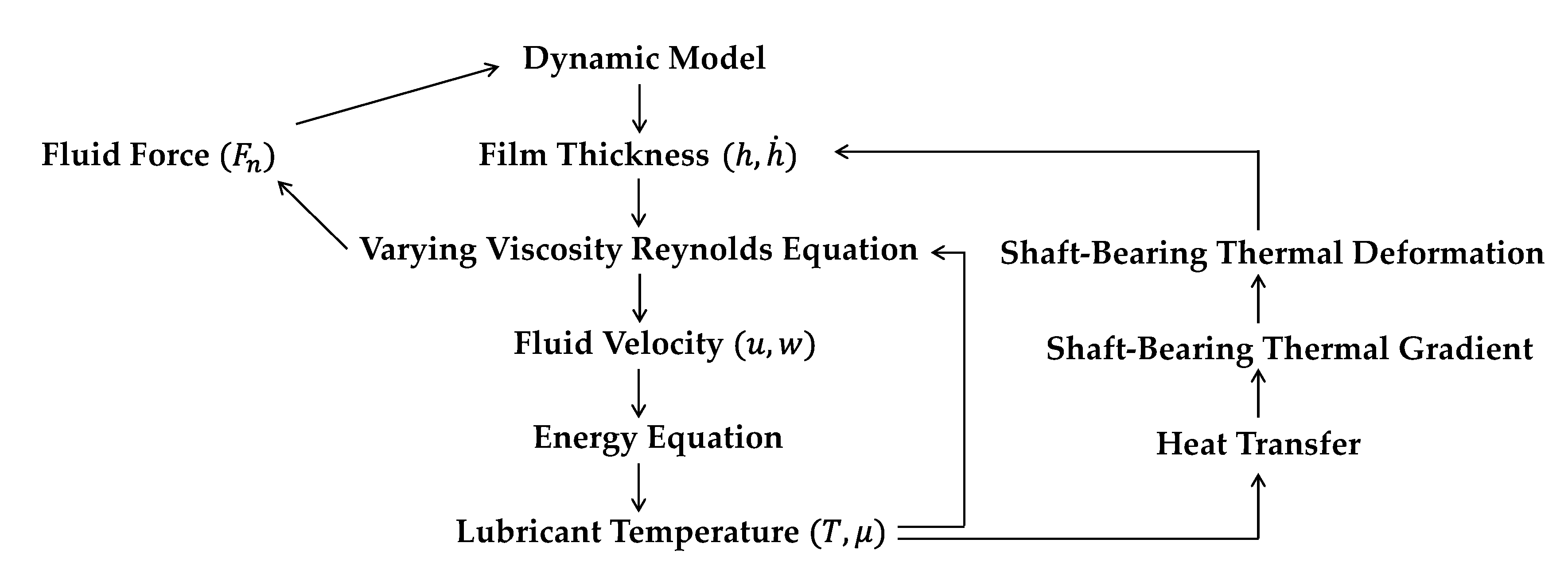
The temperature of the oil film and bearing pad is closely related to the life of the bearing. The temperature of the lubricant affects the oxidation rate of the lubricating oil, and the temperature of the pad influences the life of the Babbitt metal. This is the reason why predicting the temperature of bearings in the design stage of turbomachinery is important. The temperature change of the bearing–journal leads to the thermal deformation of the structure; this thermal deformation changes the oil film thickness at the running condition, and the changed thickness changes the temperature distribution of the bearing system by changing the viscous shearing in the oil film. This complicated interaction makes accurate temperature prediction of the bearing system difficult.
In this study, to overcome these difficulties, a 3D bearing numerical modeling approach and algorithm is presented, and the static, dynamic, and thermal characteristics of the bearing are analyzed according to the change of thermal boundary conditions. The numerical model provided in this research is based on the earlier studies performed by Suh and Palazzolo [19,20], and is an extension of their research. This research is performed based on an in-house code that has been developed in MATLAB, a commercial numerical analysis software, based on the 2019b version. It also has been updated through various research projects since 2015 when the first study was published.
This bearing model was firstly verified through comparison with the published textbook about journal bearing [35] at the development stage, and it was secondarily verified through comparison with Kulhanek’s experimental results [36]. The following are the modified and improved features adopted in this research since the bearing numerical model was first published in 2015 [19,20].
Consideration of the thermal boundary condition around shaft
Addition of Babbitt material at the inner surface of the bearing pad with the consideration of heat transfer and thermal deformation
Addition of the prescribed temperature boundary condition around the bearing–journal structure
Improvement of stability of prediction of pivot stiffness
Improvement of the boundary condition of the FE thermal deformation model
The purpose of this study is to investigate the change in bearing performance according to (a) journal boundary temperature, (b) bearing boundary temperature, and (c) lubricant supply temperature. It was found that the thermal boundary conditions make noticeable changes in bearing behavior.

2. Numerical Methods

2.1. Varying Viscosity Reynolds Equation

Viscous shearing in the thin film is the main heat source in the bearing system. Since the iso-viscosity Reynolds equation does not account for the change in viscosity in the thickness direction of the oil film, a modified equation should be used to consider heat transfer and generation in the thin film. In this study, the generalized Reynolds equation was used to consider the temperature distribution in the film thickness direction and the resulting viscosity change. An FE model was created to calculate the hydraulic pressure by discretizing the Reynolds equation. Equation (1) represents the generalized Reynolds equation derived using Newton’s second law and mass conservation law. The Reynolds equation calculates the fluid film pressure between two surfaces in relative motion.
  ·   ( D 1 p ) +   ( D 2 )   ·   ( U 2 U 1 )   +   ( h )   ·   U 1   + h t = 0
From Equation (1), assuming that the bearing pad does not produce sliding motion results in a more generic form as in Equation (2),
  ·   ( D 1 p ) +   ( D 2 )   ·   U   + h t = 0
where D 1 and D 2 are defined as
D 1 = 0 h   0 z ξ μ d ξ d z   0 h ξ μ d ξ 0 h 1 μ d ξ 0 h   0 z 1 μ d ξ   d z  
D 2 =   0 h 0 z 1 μ d ξ   d z   0 h 1 μ   d ξ  
The time derivatives of the oil film thickness (h) presented in Equations (1) and (2) were used to calculate the bearing damping coefficient, and was also used to calculate the bearing equilibrium state using the time transient approach. Lubricant viscosity is assumed to be a function of only temperature and the following Equation (5) presents the relationship between the viscosity and the temperature, where μ 0 is a viscosity at a reference temperature T 0 and β is a viscosity coefficient.
μ = μ 0 e β ( T T 0 )
For the use of the generalized Reynolds equation, the following assumptions were made.
(a)
Full laminar flow
(b)
Constant pressure in the radial (film thickness) direction
(c)
Negligible shaft curvature effect
(d)
Negligible fluid inertia
(e)
Constant fluid density
(f)
Temperature-affected viscosity as depicted in Equation (4)
(g)
Incompressible Newtonian fluid
(h)
Non-slip at the solid and fluid interface
(i)
Reynolds cavitation boundary condition with a back substitution presented by Lund and Thomsen [37].

2.2. Three-Dimensional Energy Equation

ρ c ( u T x + w T z ) = k ( 2 T x 2 + 2 T y 2 + 2 T z 2 ) + μ [ ( u y ) 2 + ( w y ) 2 ]
In the above Equation (6) x , y , and z are circumferential, radial, and axial direction, respectively. Heat convection is considered in x and z directions, where u and w are lubricant velocity profiles which are calculated by the Reynolds Equation (2), whereas the heat conduction is taken into account along all directions. Since the purpose of this study is to analyze the steady state of the bearing, the temperature change over time was not considered. The FE model is utilized to solve the energy equation using the up-winding scheme to prevent numerical error arising from the convection terms. Thermal boundary conditions should be defined to solve the energy equation. Equations (7) and (8) are heat flux and temperature conditions at the interface between the fluid film and bearing pads, respectively (boundary B, Figure 1a). r represents the bearing radial direction. R is a journal radius, and H indicates the film thickness.
k L T L r | ( r = R + H ) = k B T B r | ( r = R + H )
T L | ( r = R + H ) = T B | ( r = R + H )
Equations (9) and (10) are heat flux and temperature conditions at the interface between the spinning journal and lubricant, respectively (boundary A, Figure 1a). θ represents the bearing circumferential direction. Unlike the thermal boundary condition between the oil film and the bearing pad, the boundary condition between the journal and the oil film is complicated due to the spinning journal. In this study, orbit averaged heat flux boundary condition suggested by Gomiciaga and Keogh [38] is adopted. Their research was not about the bearing performance, but only to calculate the surface temperature of a spinning journal. On the other hand, temperature change of the journal, the resulting thermal expansion, and the corresponding change in the oil film thickness were implemented in MATLAB-based in-house code.
k J T J r | ( θ = 0 , r = R ) = k L T L r | ( θ = ω t , r = R )
T J | ( θ = 0 , r = R ) = T L | ( θ = ω t , r = R )
The temperature at the inlet end of the bearing pad ( T i n ) greatly affects bearing performance, where i denotes the pad number. This is because the temperature of the lubricant changes the viscosity and the change in viscosity affects the bearing oil film pressure. Therefore, it is very important for bearing performance analysis to consider the temperature change of the bearing inlet. Figure 2 explains whether the lubricant from the pad and the lubricant supplied from the outside mix enter the next pad. In most cases, not all lubricants from previous bearing pads enter the next pad. A portion of the hot lubricant flowing out of the bearing pads slips out between the pads, and some is mixed with cold oil supplied from the outside to enter the next pad. In this study, the mixing temperature theory is used to account for the analysis of the inlet oil temperature as described in Equation (11). Mixing coefficient ( η ) limits the amount of oil flowing from the previous pad to the next pad. It is impossible to obtain the mixing coefficient experimentally or numerically, and 0.8, which is used in most previous studies, was also adopted in this study.
T i n i ( z ) = η · Q i n i ( z ) · T o u t i 1 ( z ) + ( Q i n i ( z ) η · Q i n i ( z ) ) · T s u p p l y Q i n i ( z )

2.3. Modeling for Heat Transfer and Thermal Deformation of Journal-Bearing System

The heat generated by the viscous shear in the oil film is transferred to the bearing pads and journals bordering the oil film. The transferred energy heats the bearing and shaft, and the resulting temperature change causes thermal deformation of the structure. In this study, a 3D FE model of bearing and shaft structure was created using in-house code, and heat transfer and thermal deformation were analyzed.
Thermal deformation of the shaft and bearing pad changes the oil film thickness. The changed oil film thickness changes the pressure, thereby changing the viscous shear and changing the temperature boundary conditions of the oil film. Such heat generation, heat transfer, and thermal deformation influence each other and reach a state of dynamic and thermal convergence.
Figure 3 depicts the schematic of the workflow of the THD lubrication model presented in this study. Firstly, the film thickness profile of the TPJB is defined by the user input initial states which includes journal position, initial temperature guess of bearing structure, and the resulting thermal deformation. The film thickness profile is depicted in Equation (12), where each notation is described in Figure 4 schematically. The amount of fluid film thickness reduction by the thermal expansions of the journal and bearing pad are considered as h T E J and h T E P , respectively. Fluid film thickness ( h ) and its time derivative ( h ˙ ) is used in the Reynolds equation for the evaluation of the fluid force ( F n ) and velocity profile ( u ,   w ). The fluid velocity ( u ,   w ) is fed into the energy equation to produce the fluid film temperature and viscosity which are fed back into the generalized Reynolds equation. There, three closed loops in the bearing analysis algorithm as shown in Figure 3. The first one is in the dynamic model, where the fluid force calculated by the Reynolds equation changes the dynamic behavior, and the changed dynamic behavior affects the film thickness again. The second one is in the coupled model of the Reynolds equation and the energy equation. The lubricant temperature updated by the energy equation affects the Reynolds equation, where the changed viscosity affects the pressure distribution. The third closed loop is in the heat flux and thermal deformation model. The lubricant temperature changes the thermal boundary condition among the spinning journal, lubricant, and bearing pads. The changed boundary condition influences the thermal deformation and the resultant lubricant film thickness. The updated film thickness affects the lubricant temperature again. The main three closed loops are implemented in the in-house code. The dynamic model adopted in this study is based on the rigid body dynamic model where the pivot elastic deformation is considered based on the Hertzian contact theory.
h ( θ ) = C L P ( e x p p v t c o s ( θ p ) ) c o s ( θ ) ( e y p p v t s i n ( θ p ) ) s i n ( θ ) ( C L P C L B ) c o s ( θ θ p ) δ t i l t R s s i n ( θ θ p ) h T E J ( θ , z ) h T E P ( θ , z )

2.4. Bearing–Journal Dynamic Model

In this study, time transient analysis was performed for the steady state analysis of bearings without using the Newton–Raphson method used in most previous studies. The transient approach gives simpler algorithm than iteration scheme, where all the degrees of freedom is converging with time. Figure 5 shows the pad–journal dynamic model. The structural flexibility of the pad is ignored, and both pad and journal are assumed to be rigid bodies. For the pad dynamic analysis, fluid force ( F Reynolds ( t ) ) calculated by Reynolds equation and pivot force ( F Pivot ( t ) ) calculated by Hertzian contact theory are applied to the pad as shown in Figure 5a. Equation of motion for the pad is given in Equation (12). Each pad produces both tilting ( θ ( t ) ) and translational motion ( x p ( t ) ) at the pivot location as shown in Figure 5a. For the journal dynamic analysis, fluid force ( F Reynolds ( t ) ) and bearing load (( F Load ( t ) ) are applied as shown in Figure 5b. Journal has two degrees of freedom in x and y directions and the equation of motion is provided in Equation (14).
M pad X ¨ pad = F Reynolds + F Pivot
M journal X ¨ journnal = F Reynolds + F Load

2.5. Validation of Numerical Model

In order to verify the performance of the bearing model presented in this research, the bearing dynamic properties experimentally measured by Kulhenek [36] were compared with the results calculated by the numerical model presented in this study. Table 1 shows the bearing design parameters taken from Kulhanek’s paper [36]. In addition to the factors shown in this table, actual bearings have various factors such as pad thickness, thermal boundary conditions and pivot stiffness, and the resulting change in performance cannot be ignored. The experimental approaches that have been carried out before assumed the negligible influence of these factors. That is why this study attempts to analyze the performance change according to the thermal boundary conditions around the bearing system. In this study, it is assumed that 43 °C of lubricant is flowing around the bearing pad and 50 °C of air is present around the spinning shaft. The thickness of the pad in the radial direction was assumed to be 10mm, and it was modeled as a cylinder–cylinder pivot.
Figure 6 compares the dynamic coefficients measured experimentally by Kulhanek [36] and the results calculated by the numerical model provided in this paper. The results of this analysis predicted a larger value for both the x and y-direction bearing stiffness, and the results of this study showed lower values for the viscosity coefficient. This error is considered to be caused by the addition of the condition assumed in this study in addition to the bearing design factor given in Kulhanek’s paper [36].

2.6. Simulation Model

To investigate the effect of thermal boundary condition on TPJB behavior, the THD lubrication model is adopted. Lubricant and bearing material properties are provided in Table 2 and Table 3, respectively. As described in Table 4, bearing load is applied between pads (LBP). The simulated bearing model is described in Figure 7 where geometry and load direction are described in (a) and the cross section of FE model is in (b). The FE model of shaft and bearing pads are used for the analysis of heat conduction and thermal deformation, where the FE nodal information of both temperature analysis and thermal expansion are identical. The size of the bearing used in this study was reduced being compared with the actual bearing configuration while maintaining the shape ratio of that. In order to consider the same performance as the actual bearing, the operating conditions having the same Sommerfeld number were used by changing the rotor spin speed.
In this study, the thermal boundary conditions around the tilting pad journal bearing system were divided into three areas. Figure 8 describes the three different areas. It is difficult to quantitatively explain the change in bearing performance due to thermal boundary conditions in each area. In this study, in order to quantitatively analyze these effects, a prescribed temperature condition was assigned to the outer surface of the finite element model to give the bearing ( T Pad ) and journal ( T Journal ) thermal boundary conditions, and in the case of lubricant, the supplied lubricant temperature ( T Lube ) was assigned as described in Figure 8.
Table 5 explains the running conditions for the analysis of the thermal boundary effects. Model 1 and 2 have two different rotor spin speeds, and has the identical thermal boundary condition, where five different values of T Pad are applied, and T Journal and T Lube are constant at 50 °C. Model 3 and 4 have the identical thermal boundary conditions and different rotor spin speed, and model 5 and 6 do so. The sixth column of Table 5 indicates the line style for each model number used for describing the simulation results in the following section.

3. Simulation Results and Discussion

3.1. Bearing Static and Dynamic Behavior

Figure 9 depicts the bearing static characteristics. 1000 rpm conditions are illustrated with a square notation and 3600 rpm are illustrated with a diamond notation. Each thermal condition is drawn with different line style as described in Table 5. Firstly, the journal eccentricity ratio is drawn in Figure 9a. With the increasing boundary temperature of pad ( T Pad ) and increasing lubricant supply temperature ( T Lube ), the eccentricity ratio is increasing. On the other hands, increased shaft boundary temperature ( T Journal ) decreases the eccentricity ratio. Increased boundary temperature around the pad ( T Pad ) and supply temperature ( T Lube ) might tighten the bearing clearance, leading to the increased eccentricity ratio; the increased shaft boundary temperature ( T Journal ) might heat the lubricant and the clearance might be increased, leading to the reduced eccentricity ratio.
Journal attitude angle is illustrated in Figure 9b. The ideal tilting pad journal bearing has a zero attitude angle, and this property is closely related to the zero cross-coupled dynamic characteristics. However, due to thermal deformation, elastic deformation, and other unknown reasons of the bearing structure, there may be a case where the attitude angle is not zero, and it is not well seen in general analysis models. The numerical model presented in this research adopts the 3D THD lubrication model where the 3D thermal deformation resulting from the 3D temperature change is considered. With the increasing boundary temperature around the bearing pad ( T Pad ), attitude angle decreased, whereas the increasing lubricant supply temperature ( T Lube ) increased the attitude angle. The tilting angle of bearing pad no. 5 and non-dimensional pivot deformation are illustrated in Figure 9c,d. The non-dimensional is calculated by dividing the pivot deformation by the initial bearing clearance. The effects of boundary temperature around the bearing pad and the shaft have different effects on tilt angle and pivot deformation. The boundary temperature around the bearing system and the lubricant supply temperature leads to complex physical phenomena. For example, increased lubricant supply temperature ( T Lube ) may lead to two different phenomena. The first scenario is that the increased T Lube may decrease lubricant viscosity and lower the heat generation. The decreased heat generation may lead to increase the film clearance arising from the lowered thermal expansion of the journal and bearing pads. The second opposite scenario is that the increased T Lube heats the bearing pad and journal, and the thermally expanded structure may decrease the film clearance. These two different cases are possible but depends on complex physical boundary condition and bearing system configurations.
Bearing dynamic properties are illustrated in Figure 10, where the synchronously reduced dynamic coefficients are used with the assumption of the synchronous vibration of bearing pads [19,20]. In the case of the stiffness coefficients depicted in Figure 10a,b, increased boundary temperature around bearing/journal and lubricant supply temperature stiffen the bearing system except for the T Lube = 80 °C case at 3600 rpm. It seems that the increased boundary temperature ( T Pad ,   T Journal ) causes thermal expansion of the bearing–journal structure leading to the decreased film thickness. It also possible that the increased lubricant supply temperature ( T Lube ) heats the structure and the structure is thermally expanded. This thermal expansion stiffens the bearing. However, for the case of T Lube = 80 °C at 3600 rpm, the bearing is softened by the increased lubricant supply temperature. In this case, the opposite scenario is possible—that the increased lubricant temperature decreases the fluid viscosity, leading to the decreased bearing stiffness.
Unlike the bearing stiffness coefficient, the damping coefficient tends to be complex as shown in Figure 10c,d. When the boundary temperature of the journal is increased, the damping coefficient increases in most cases. However, an increase in the pad boundary temperature decreases the damping coefficient in most cases. In particular, when the pad boundary temperature ( T Pad ) is 80 °C, the reduction rate is remarkable. The change of the damping coefficient according to the lubricant supply temperature ( T Lube ) shows different patterns depending on the direction (x or y). The damping coefficient in the horizontal direction ( C x x ) increases with the increase in the supply temperature of the lubricant, and then decreases significantly when the supply temperature becomes 80 °C. However, it can be seen that the damping coefficient in the vertical direction ( C y y ) shows the opposite tendency depending on the journal spin speed.

3.2. Bearing Thermal Behavior

This section illustrates the bearing thermal behavior with different thermal boundary conditions. In order to understand the tendency of the change in static and dynamic characteristics of the bearing in the previous section, it is necessary to look closely at the change in the thermal characteristics of the bearing in this section. Figure 11a,b illustrates the pad temperature at 75% circumferential position and peak temperature, respectively. The 75% temperature is measured at 75% of the bearing pad circumferential and journal spin direction. They produce almost identical results; that is why the API standard requires 75% temperature as a maximum pad temperature. Increasing pad boundary temperature ( T Pad ) increases pad maximum temperature, which can be easily expected. An increase in the shaft boundary temperature ( T Journal ) does slightly decrease the pad temperature.
Figure 11c shows an interesting phenomenon regarding the maximum oil film temperature. The maximum oil film temperature is an important factor closely related to the bearing pad Babbitt life and oil oxidation. The pad boundary temperature ( T Pad ) has a greater influence on the peak lubricant temperature than the oil supply temperature ( T Lube ). It can be seen that the maximum lubricating oil temperature change when increased from 0 °C to 80 °C is more sensitive to the pad boundary temperature change ( T Pad ) than the lubricating oil supply temperature ( T Lube ). Maximum shaft temperature is more closely related to the lubricant supply temperature ( T Lube ) than the shaft boundary temperature ( T Journal ) as shown in Figure 11d.
Figure 11e shows the non-dimensional thermal expansion of the journal, which is the ratio of journal radial thermal expansion at the axial center and bearing clearance ( C b ). The thermal expansion of the journal seems to be more sensitive to the change in the lubricant supply temperature ( T Lube ) than the change in the boundary temperature of the shaft ( T Journal ) and bearing pad ( T Pad ). This is believed to be due to the direct contact of the supply lubricant with the journal.
Figure 11f shows the non-dimensional minimum film thickness, which is the ratio of minimum film thickness and bearing clearance ( C b ). Increasing the pad boundary ( T Pad ) and supply oil temperature ( T Lube ) reduces the minimum oil film thickness, but increasing the journal boundary temperature creates a complex tendency to increase and decrease the minimum oil film thickness. The results shown in Figure 11f are related to this phenomenon depicted in Figure 9a. With the increasing boundary temperature of pad ( T Pad ) and increasing lubricant supply temperature ( T Lube ), eccentricity ratio was increasing, while increased shaft boundary temperature ( T Journal ) decreased the eccentricity ratio. Reduced eccentricity ratio is analogous to the increased minimum film thickness.
Figure 12 shows the cross-section view of the temperature distribution on spinning journal, lubricant, and bearing pads at the axial center position. Lubricant thickness is exaggerated for the readers to recognize the fluid film temperature easily. Figure 12a,c,e are 1000 rpm cases and b,d,f are 3600 rpm cases. Increased rotor spin speed produces higher maximum temperature. As discussed in Figure 11a,b, 75% location of bearing pad is around the maximum bearing temperature.
Figure 13 presents the film thickness distribution on each bearing pad for three cases (models no. 2, 4, and 6). The film thickness distribution is affected by pivot elastic deformation, pad tilting angle, journal position, and thermal expansion of both pad and journal as described in Equation (12). The red dot on each pad indicates the nodal position of minimum film thickness. Figure 13b shows that the minimum film thickness occurs at the axial end of bearing, whereas it happens at the axial center. It can be seen that the thermal deformation at both axial ends of the journal is greater than at the axial center, so that the minimum oil film thickness occurs at both ends in the axial direction. With the 2D bearing model, it is impossible to predict the bearing performance with the consideration in axial direction. Figure 14 shows the fluid film pressure on each pad for the simulation model no. 6 with T Lube = 80 °C.
In this study, in addition to the temperature boundary condition, the change in the bearing characteristics according to the rotor spin speed was examined. In addition to the rotational speed of the journal, the performance change can be evaluated by changing the shaft radius, bearing clearance, lubricant viscosity, and load. For example, increasing the rotor spin speed increases the Sommerfeld number, so increasing the lubricant viscosity or increasing the journal radius increases the Sommerfeld number. In addition, an increase in the bearing load and a decrease in a bearing clearance increase the Sommerfeld number. Bearings with the same Sommerfeld number have the same dimensionless characteristics if the viscosity change due to bearing heat generation and the performance change due to thermal deformation are ignored. If the design variable or operating condition other than the rotor spin speed is changed, similar performance changes can be predicted according to the change of the Sommerfeld number.

4. Conclusions

Recently, commercial software has been used to analyze complex phenomena in bearings, but for this, a huge amount of time and cost is required, such as there is for using a supercomputer. For this reason, it is almost impossible to analyze considering various conditions as in this study. This study analyzed and compared the static/dynamic and thermal characteristics of the TPJB according to the thermal boundary conditions of bearing pads and shafts and the lubricant supply temperature. For the numerical modeling of TPJB, a 3D FE model was utilized to model the heat transfer and thermal deformation of the bearing pad and journal structure. The varying viscosity Reynolds equation and 3D energy equation were modeled by the FE method and were coupled via the temperature–viscosity relation. Heat flux among the spinning journal–lubricant–bearing pads were modeled with the consideration of the heat flux boundary condition at the interface among the shaft, lubricant, and pad.
It is complicated to quantify the ambient temperature boundary conditions in the actual bearing operating conditions. The bearing pads are surrounded by air and circulating oil, and in the case of journals, they are in contact with hot or cold working fluids and outside air. From cryogenic space launch rocket pumps to hot turbines, the temperature distribution around the bearings can vary widely. In this study, rather than what the actual boundary temperature is, sensitivity and tendency of the change in bearing performance according to the temperature change at the boundary of each element constituting the bearing system were investigated.
Table 6 summarizes the bearing performance changes in accordance with the thermal boundary conditions around the bearing system and the lubricant supply temperature. The results provided in this study provide guidance to bearing designers and troubleshooters of journal bearing for avoiding the unpredictable problems through judicious selection of physical parameters

Author Contributions

Conceptualization, J.S. and J.-H.H.; methodology, C.K.; software, J.S.; validation, J.S.; formal analysis, J.S.; investigation, J.S.; writing—original draft preparation, J.S.; writing—review and editing, J.-H.H. and J.S.; visualization, J.S.; supervision, J.-H.H.; funding acquisition, J.S. and C.K. All authors have read and agreed to the published version of the manuscript.

Funding

This research was partially supported by the National Research Foundation of Korea (NRF) funded by the Ministry of Education (Grant No. NRF-2018R1C1B5043572, NRF-2017R1A6A1A03015562 and NRF-2017R1D1A1B-03035405) and the GRRC program of Gyeonggi province [(GRRC-KPU2020-B02), Multi-material Machining Innovative Technology Research Center].

Conflicts of Interest

The authors declare no conflict of interest.

Nomenclature

The majority of symbols and notations used throughout the paper are defined below for quick reference. Others are clarified with their appearance in case of need.
h Film thickness
μ Lubricant viscosity
U Shaft surface linear velocity
t Time
T Temperature
x Circumferential position
y Radial position
z Axial position
r Radial position
ρ Density
c Heat capacity
k Heat conductivity
Q Flow rate
e x x-component of journal position
e y y-component of journal position
C b Bearing clearance
δ t i l t Pad tilt angle
p p v t Pivot displacement
θ Circumferential nodal position
C p Pad clearance
θ p Pivot angular position
R Journal radius

References

  1. Knight, J.D.; Niewiarowski, A.J. Effects of two film rupture models on the thermal analysis of a journal bearing. J. Tribol. 1990, 112, 183–188. [Google Scholar] [CrossRef]
  2. Taniguchi, S.; Makino, T.; Takeshita, K.; Ichimura, T. A thermohydrodynamic analysis of large tilting-pad journal bearing in laminar and turbulent flow regimes with mixing. J. Tribol. 1990, 112, 542–548. [Google Scholar] [CrossRef]
  3. Knight, J.D.; Ghadimi, P. Effects of modified effective length models of the rupture zone on the analysis of a fluid journal bearing. Tribol. Trans. 1992, 35, 29–36. [Google Scholar] [CrossRef]
  4. Kim, J.; Palazzolo, A.B.; Gadangi, R.K. TEHD analysis for tilting-pad journal bearings using upwind finite element method. Tribol. Trans. 1994, 37, 771–783. [Google Scholar] [CrossRef]
  5. Kim, J.; Palazzolo, A.; Gadangi, R. Dynamic characteristics of TEHD tilt pad journal bearing simulation including multiple mode pad flexibility model. J. Vib. Acoust. 1995, 117, 123–135. [Google Scholar] [CrossRef]
  6. Gadangi, R.K.; Palazzolo, A.B. Transient analysis of tilt pad journal bearings including effects of pad flexibility and fluid film temperature. J. Tribol. 1995, 117, 302–307. [Google Scholar] [CrossRef]
  7. Desbordes, H.; Fillon, M.; Freňe, J.; Wai, C.C.H. The effects of three-dimensional pad deformations on tilting-pad journal bearings under dynamic loading. J. Tribol. 1995, 117, 379–384. [Google Scholar] [CrossRef]
  8. Fillon, M.; Desbordes, H.; Freňe, J.; Wai, C.C.H. A global approach of thermal effects including pad deformations in tilting-pad journal bearings submitted to unbalance load. J. Tribol. 1996, 118, 169–174. [Google Scholar] [CrossRef]
  9. Gadangi, R.K.; Palazzolo, A.B.; Kim, J. Transient analysis of plain and tilt pad journal bearings including fluid film temperature effects. J. Tribol. 1996, 118, 423–430. [Google Scholar] [CrossRef]
  10. Monmousseau, P.; Fillon, M. Frequency effects on the TEHD behavior of a tilting-pad journal bearing under dynamic loading. J. Tribol. 1999, 121, 321–326. [Google Scholar] [CrossRef]
  11. Nassab, S.A.G.; Moayeri, M.S. Three-dimensional thermohydrodynamic analysis of axially grooved journal bearings. Proc. Inst. Mech. Eng. Part J J. Eng. Tribol. 2002, 216, 35–47. [Google Scholar] [CrossRef]
  12. Nicholas, J.C. Tilting pad journal bearings with spray-bar blockers and by-pass cooling for high speed, high load applications. In Proceedings of the 32nd Turbomachinery Symposium, Texas A&M University, Turbomachinery Laboratories, Houston, TX, USA, 8–11 September 2003. [Google Scholar]
  13. Fatu, A.; Hajjam, M.; Bonneau, D. A new model of thermoelastohydrodynamic lubrication in dynamically loaded journal bearings. J. Tribol. 2005, 128, 85–95. [Google Scholar] [CrossRef]
  14. Brito, F.; Miranda, A.; Bouyer, J.; Fillon, M. Experimental investigation of the influence of supply temperature and supply pressure on the performance of a two-axial groove hydrodynamic journal bearing. J. Tribol. 2006, 129, 98–105. [Google Scholar] [CrossRef] [Green Version]
  15. Liu, D.; Zhang, W.; Zheng, T. A simplified one-dimensional thermal model for journal bearings. J. Tribol. 2007, 130, 011003. [Google Scholar] [CrossRef]
  16. Bang, K.-B.; Kim, J.-H.; Cho, Y.-J. Comparison of power loss and pad temperature for leading edge groove tilting pad journal bearings and conventional tilting pad journal bearings. Tribol. Int. 2010, 43, 1287–1293. [Google Scholar] [CrossRef]
  17. Thorat, M.R.; Pettinato, B.C.; De Choudhury, P. Metal temperature correlations in tilting pad journal bearings. J. Eng. Gas. Turbines Power 2014, 136, 112503. [Google Scholar] [CrossRef]
  18. Tschoepe, D.P.; Childs, D. Measurements versus predictions for the static and dynamic characteristics of a four-pad, rocker-pivot, tilting-pad journal bearing. J. Eng. Gas. Turbines Power 2014, 136, 052501. [Google Scholar] [CrossRef] [Green Version]
  19. Suh, J.; Palazzolo, A. Three-dimensional dynamic model of TEHD tilting-pad journal bearing—Part I: Theoretical modeling. J. Tribol. 2015, 137, 041703. [Google Scholar] [CrossRef]
  20. Suh, J.; Palazzolo, A. Three-dimensional dynamic model of TEHD tilting-pad journal bearing—Part II: Parametric studies. J. Tribol. 2015, 137, 041704. [Google Scholar] [CrossRef]
  21. Chang, G.; Wang, Y.; Zhong, N.; Chen, Y.; Yin, Z. Study on the performance of journal bearings in different lubricants by CFD and FSI method with thermal effect and cavitation. MATEC Web Conf. 2018, 249, 03006. [Google Scholar]
  22. Mo, J.; Guangyao, Y.; Pan, X.; Zheng, S.; Shuiying, Z. A thermohydrodynamic analysis of the self-lubricating bearings applied in gear pumps using computational fluid dynamics method. J. Tribol. 2017, 140, 011102. [Google Scholar] [CrossRef]
  23. Nichols, B.R.; Fittro, R.; Goyne, C. Steady-state tilting-pad bearing performance under reduced oil supply flow rates. J. Tribol. 2018, 140, 051701. [Google Scholar] [CrossRef]
  24. Bouyer, J.; Fillon, M.; Hélène, M.; Beaurain, J.; Giraudeau, C. Behavior of a two-lobe journal bearing with a scratched shaft: Comparison between theory and experiment. J. Tribol. 2018, 141, 021702. [Google Scholar] [CrossRef]
  25. Bouyer, J.; Fillon, M. An experimental analysis of misalignment effects on hydrodynamic plain journal bearing performances. J. Tribol. 2001, 124, 313–319. [Google Scholar] [CrossRef]
  26. El-Butch, A.; Ashour, N. Transient analysis of misaligned elastic tilting-pad journal bearing. Tribol. Int. 2005, 38, 41–48. [Google Scholar] [CrossRef]
  27. Suh, J.; Choi, Y.-S. Pivot design and angular misalignment effects on tilting pad journal bearing characteristics: Four pads for load on pad configuration. Tribol. Int. 2016, 102, 580–599. [Google Scholar] [CrossRef]
  28. Yang, P.; Yuan, Q.; Chen, R. Experimental research on the tilting pad bearing under the high temperature of inlet oil. Ind. Lubr. Tribol. 2018, 70, 935–941. [Google Scholar] [CrossRef]
  29. Abdollahi, B.; Andrés, L.S. Improved estimation of bearing pads’ inlet temperature: A model for lubricant mixing at oil feed ports and validation against test data. J. Tribol. 2018, 141, 031703. [Google Scholar] [CrossRef]
  30. Yang, J.; Palazzolo, A. Three-dimensional thermo-elasto-hydrodynamic computational fluid dynamics model of a tilting pad journal bearing—Part I: Static response. J. Tribol. 2019, 141, 1–44. [Google Scholar] [CrossRef]
  31. Yang, J.; Palazzolo, A. Three-dimensional thermo-elasto-hydrodynamic computational fluid dynamics model of a tilting pad journal bearing—Part II: Dynamic response. J. Tribol. 2019, 141, 061703-35. [Google Scholar] [CrossRef]
  32. Rindi, A.; Rossin, S.; Conti, R.; Frilli, A.; Galardi, E.; Meli, E.; Nocciolini, D.; Pugi, L. Efficient models of three-dimensional tilting pad journal bearings for the study of the interactions between rotor and lubricant supply plant. J. Comput. Nonlinear Dyn. 2016, 11, 011011. [Google Scholar] [CrossRef]
  33. Polyakov, R.; Shutin, D.; Savin, L.; Babin, A. Peculiarities of reactions control for rotor positioning in an active journal hybrid bearing. Int. J. Mech. 2016, 10, 62–67. [Google Scholar]
  34. Babin, A.; Kornaev, A.; Rodichev, A.; Savin, L. Active thrust fluid-film bearings: Theoretical and experimental studies. Proc. Inst. Mech. Eng. Part J J. Eng. Tribol. 2019, 234, 261–273. [Google Scholar] [CrossRef]
  35. Someya, T. Journal-Bearing Databook; Springer Science & Business Media: Berlin, Germany, 2013. [Google Scholar]
  36. Kulhanek, C.D.; Childs, D. Measured static and rotordynamic coefficient results for a rocker-pivot, tilting-pad bearing with 50 and 60% offsets. J. Eng. Gas. Turbines Power 2012, 134, 052505. [Google Scholar] [CrossRef]
  37. Lund, J.W.; Thomsen, K.K. A calculation method and data for the dynamic coefficients of oil-lubricated journal bearings. Topics in Fluid Film Bearing and Rotor Bearing System Design and Optimization. 1978, p. 1000118. Available online: https://dyrobes.com/paper/a-calculation-method-and-data-for-the-dynamic-coefficients-of-oil-lubricated-journal-bearings/ (accessed on 20 July 2020).
  38. Gomiciaga, R.; Keogh, P.S. Orbit induced journal temperature variation in hydrodynamic bearings. J. Tribol. 1999, 121, 77–84. [Google Scholar] [CrossRef]
Figure 1. Heat flux boundary conditions and deformation in bearing–journal system.
Applsci 10 07540 g001
Figure 2. Schematic diagram of oil inlet groove and boundary conditions at pad edges.
Applsci 10 07540 g002
Figure 3. Thermo-hydrodynamic lubrication model.
Applsci 10 07540 g003
Figure 4. Schematic diagram for the calculation of the fluid film thickness.
Applsci 10 07540 g004
Figure 5. Tilting pad journal bearing dynamic model: (a) pad dynamic model; (b) journal dynamic model.
Applsci 10 07540 g005
Figure 6. Nondimensionalized dynamic characteristics: (a) k x x ; (b) k y y ; (c) c x x ; (d) c y y .
Applsci 10 07540 g006
Figure 7. Tilting pad journal bearing model: (a) geometry check plot and load direction; (b) bearing finite element model.
Applsci 10 07540 g007
Figure 8. Thermal boundary conditions around bearing-lubricant-shaft numerical model: (a) cross-section view; (b) side view.
Applsci 10 07540 g008
Figure 9. Bearing static characteristics: (a) eccentricity ratio; (b) attitude angle; (c) tilt angle of pad no.5; (d) non-dimensional pivot deformation.
Applsci 10 07540 g009
Figure 10. Nondimensionalized dynamic characteristics: (a) k x x ; (b) k y y ; (c) c x x ; (d) c y y .
Applsci 10 07540 g010
Figure 11. Bearing thermal characteristics: (a) 75% bearing pad temperature; (b) peak bearing pad temperature; (c) peak lubricant temperature; (d) peak journal temperature; (e) non-dimensional journal thermal expansion; (f) non-dimensional minimum film thickness.
Applsci 10 07540 g011
Figure 12. Temperature distribution at the axial center: (a) T Shaft = 60 °C (1000 rpm); (b) T Shaft = 60 °C (3600 rpm); (c) T Pad = 60 °C (1000 rpm); (d) T Pad = 60 °C (3600 rpm); (e) T Lube = 60 °C (1000 rpm); (f) T Lube = 60 °C (3600 rpm).
Applsci 10 07540 g012
Figure 13. Fluid film thickness distribution: (a) model no. 2 ( T Pad = 80 °C, T Shaft = 50 °C, T Lube = 50 °C); (b) model no. 4, ( T Pad = 50 °C, T Shaft = 80 °C, T Lube = 50 °C); (c) model no. 6, ( T Pad = 50 °C, T Shaft = 50 °C, T Lube = 80 °C).
Applsci 10 07540 g013
Figure 14. Pressure distribution: model no. 6 (Pa), ( T Pad = 50 °C, T Shaft = 50 °C, T Lube = 80 °C).
Applsci 10 07540 g014
Table 1. Test bearing parameters. [36].
PropertiesData
Number of pads5
ConfigurationLBP
Pad arc angle (°)57.87
Rotor diameter (mm)101.587
Pad axial length (mm)60.325
Radial pad clearance (mm)0.112
Lubricant typeISO VG 32
Oil supply temperature (°C)43
Unit load (kPa)1034
Table 2. Lubricant properties.
PropertiesData
Viscosity at 40 °C (N·s/m2)0.0365
Viscosity coefficient (Pa·s)0.0297
Heat capacity (J/kg·°C)1,886
Heat conductivity (W/(mK))0.136
Density (kg/m3)877
Table 3. Material properties.
Journal
Reference temperature for thermal expansion (°C)25
Therm. Exp. Coeff (1/°C)0.0000122
Heat Conductivity (W/(m °C))42.6
Heat Capacity (J/(kg °C))453.6
Density (kg/m3)7850
Young’s Modulus (Pa)2.05 × 10¹¹
Poisson’s Ratio0.3
Pad Material
Ref. Temp. for Texp (°C)25
Therm. Exp. Coeff (1/°C)0.0000121
Heat Conductivity (W/(m °C))51.9
Heat Capacity (J/(kg °C)453.6
Density (kg/m3)7858
Young’s Modulus (Pa)2.00 × 10¹¹
Poisson’s Ratio0.3
Babbitt Material
Ref. Temp. for Texp (°C)25
Therm. Exp. Coeff (1/°C)0.000021
Heat Conductivity (W/(m °C))55
Heat Capacity (J/(kg °C)230
Density (kg/m3)7390
Young’s Modulus (Pa)5.3 × 10¹⁰
Poisson’s Ratio0.3
Housing Material
Young’s Modulus (Pa)1.86 × 10¹¹
Poisson’s Ratio0.3
Table 4. Bearing system configurations.
Load TypeLBP
Number of pads5
Pad arc length (°)60
Offset0.5
Preload0.4
Bearing axial length (mm)175
Pad thickness (mm)35
Babbitt thickness (mm)3.5
Journal diameter (mm)245
Shaft left/right length (mm)175
Load direction (deg.)270 (−y)
Load (N)60,270
Table 5. Running conditions.
Model No.Rotor Spin Speed (rpm) T P a d (°C) T J o u r n a l (°C) T L u b e (°C)Line Style
110000, 20, 40, 60, 805050 Applsci 10 07540 i001
236000, 20, 40, 60, 805050 Applsci 10 07540 i002
31000500, 20, 40, 60, 8050 Applsci 10 07540 i003
43600500, 20, 40, 60, 8050 Applsci 10 07540 i004
5100050500, 20, 40, 60, 80 Applsci 10 07540 i005
6360050500, 20, 40, 60, 80 Applsci 10 07540 i006
Table 6. Effect of thermal boundary condition on tilting pad journal bearing behavior.
Bearing Characteristics Increase   in   T P a d Increase   in   T J o u r n a l Increase   in   T L u b e
Eccentricity ratio
Attitude angle
Tilt angle of pad no. 5
Pivot deformation
Bearing stiffness coefficients
Bearing damping coefficients↗↘
Peak temperature of pad
Peak temperature of journal
Peak temperature of lubricant
Journal thermal expansion
Minimum film thickness
Publisher’s Note: MDPI stays neutral with regard to jurisdictional claims in published maps and institutional affiliations.

