1. Introduction
Pumping systems are among the main electrical energy consumers in industry and household applications. These systems account for approximately 22% of the energy consumed by electrical motors [
1]. The problem of the energy efficiency of pumping systems is topical among the researchers [
2,
3]. Although most of the pumping units are still using drives without variable speed control [
3], in some countries almost 20–30% of pumping systems are already supplied with variable speed drives (VSDs), due to their high efficiency [
4].
Often, instead of a high-power single pumping system, a multi-pump system with two or more pumps with a lower power is used [
5,
6,
7]. This type of solution can provide cheap operation costs, easier maintenance, and a longer lifespan of a pumping unit. In addition, there is a possibility of flowrate control in a multi-pump system without a pressure drop and significant efficiency drop of pumping units. It is almost impossible to achieve by means of either throttling or speed control in a single-pump pumping system [
8]. Maintaining the pressure in the system at flowrate control is crucial in applications with high static pressure [
6,
7].
The possibility of energy loss reduction for the multi-pump system is achieved with the help of switching off some of the pumps at low flowrates, as well as by optimizing the operation of separate pumps, in the case where they are supplied with variable speed drives [
6,
7,
8].
A wide variety of articles concern the energy efficiency issues of multi-pump systems. In [
8] for example, the optimization of multi-pump system operation is considered in order to increase reliability and improve the efficiency of the system. The efficiency of the two systems is compared depending on the fluid flowrate. For pumps operating in parallel mode, the possibility of the optimal control strategy is studied with the help of a genetic algorithm. The obtained results show that the highest efficiency is achieved by ensuring the same flowrate of two pumps. This article also studies the comparison of a system consisting of two pumps with one frequency converter and the same system with two separate frequency converters for each pumping unit. It is shown that the latter system has better efficiency.
In [
9], the solution for energy efficiency boosting in a multi-pump system with variable speed drives is proposed. The concept does not include any additional flow meters or measuring instruments for flow-head characteristics. An original strategy for multi-pump system control using throttling and speed control methods based on flow rate estimation is proposed.
In [
10], an original algorithm is proposed for reliable prediction of the operation of parallel controlled pumps in the multi-pump system and the control of the number of working pumps that is optimal from the energy efficiency point of view for variable speed drives without throttling implementation.
In [
11], the parallel operation of two pumps with the same parameters of the nominal pressure and different values of the nominal flow is investigated. It is shown that the overall efficiency of the system decreases with an increase in the ratio of the nominal flow rates for individual pumps. For comparison, 28 various combinations of pump system parameters were investigated.
In [
12,
13], the parallel operation of the multi-pump system consisting of four pumps is considered, where the flowrate is controlled by three different methods (throttling, bypass, and by the speed regulation). A genetic algorithm is used to find the proper energy-efficient management strategy.
In [
14], a system with five parallel pumps is investigated. The power consumption is compared for different cases. For instance, when only one frequency converter is used and in the case of using five separate frequency converters for each particular pump. It is shown that in the case of application of variable speed drives for each pump instead of one variable speed drive leads to a reduction of power consumption from the grid by 2.5%.
In [
15], the optimization of the energy consumption of three parallel pumps without rotational speed regulation is considered. In [
16], the optimization of the energy consumption of a system of seven parallel pumps of various types, some of which are equipped with VSD, is considered. In [
17], the energy consumption of three pumps is compared when varying the number of VSDs. In [
18], the energy consumption of pumping systems employing 2–4 parallel pumps without rotational speed regulation is compared.
The analysis shows that the use of variable speed drives for each pump in a multi-pump system is generally the most energy-efficient solution. A large number of proposed various control strategies achieved by using different optimization methods demonstrate the complexity and necessity to take into account a large number of parameters when optimizing the energy consumption of a multi-pump system. A series of research works are devoted to comparing the energy consumption of various multi-pump systems [
6,
14,
15,
16,
17,
18,
19]. One of the issues that is not sufficiently described in the literature is the strategy for an optimal number of running pump selections in a multi-pump system for specific applications. In the case of low-power pumping units, the preferred option between single-pump and multi-pump configurations may not be obvious.
In particular, despite a large amount of literature on the analysis of the energy efficiency of various schemes of multi-pump systems, the energy efficiency of a pump unit with a single pump equipped with a VSD and a system with two pumps only one of which is equipped with a VSD has not been compared earlier. This case is of great practical importance since both considered configurations can be used in small pumping stations.
The pumping system with two motors and one frequency converter is a special case of multi-motor pumping stations with a single frequency converter (single-drive multi-pump systems) for fluid machinery applications. Such systems are widely used in the electric drive of pumping and compressor stations employing pump/compressor units of low rated power. This makes it possible to significantly reduce the capital costs of such pumping stations while providing the smooth regulation of the pressure/flow rate [
20,
21,
22].
In order to compare the operation of pumps with the mentioned topology, this paper presents a quantitative assessment of the energy consumption of a system consisting of two parallel pumps (0.75 kW), in comparison with a system containing one single pump (1.5 kW) that is driven by a VSD. A single-pump system contains only one variable speed drive for the induction motor (IM). The multi-pump system with two pumps in parallel contains one induction motor, fed directly from the grid, and a second induction motor, fed by the frequency converter. An induction motor connected directly to the grid drives a pump with throttle control. Both pumping systems have the same fluid flowrate that is specific for open loop pumping systems.
With the help of the mathematical model, data from the catalogues provided by the manufacturer, and experimental data, the energy consumption of the two types of pump system topologies is compared. Since the cost of a variable frequency drive is a significant part of the total price of a low-power pump system, the case of parallel operation of two pumps using one VSD is considered. In this study, we examine the feasibility of using two parallel pumps in the multi-pump system instead of a single-pump system, mainly taking into account energy efficiency.
2. Structure of the Examined Pump Systems
The following structures of the pumping system are examined in the project:
The pumping system with a single pump supplied with a VSD, the nominal power of 1500 W, and the nominal speed of 2900 rpm. Water supply is controlled by the speed control method;
The multi-pump system with two parallel pumps, the nominal power of 750 W, and the nominal speed of 2900 rpm. The electric drive of the first pump is equipped with a VSD, and the second pump has an induction motor connected directly to a grid. The water supply is controlled by the VSD of the first pump and by throttling of the second pump.
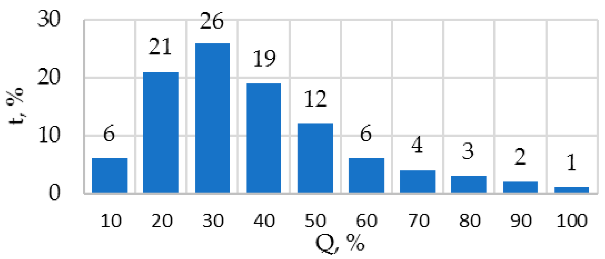
The energy consumption of these pump systems is compared for an application when the water supply during the cycle corresponds to the dependence typical for open loop pump systems [
23]. The dependence is shown in
Figure 1. The period of the cycle equals 24 h.
For a single-pump system, the pump Calpeda—B—40/12C/A (model 1) is chosen; the rated power is 1500 W [
24]. For a multi-pump system, two pumps Calpeda—B—NM 32/12D (model 2) are chosen; the rated power is 750 W [
24]. The rated rotational speed is 2900 rpm.
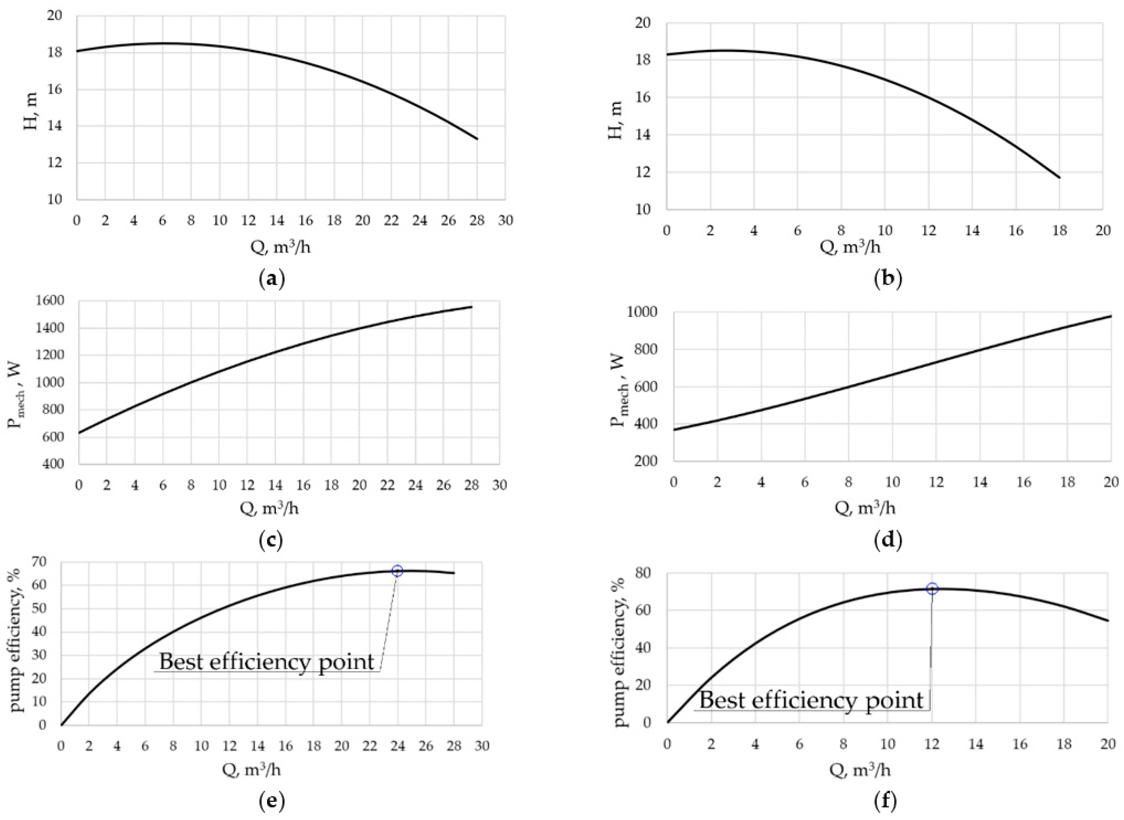
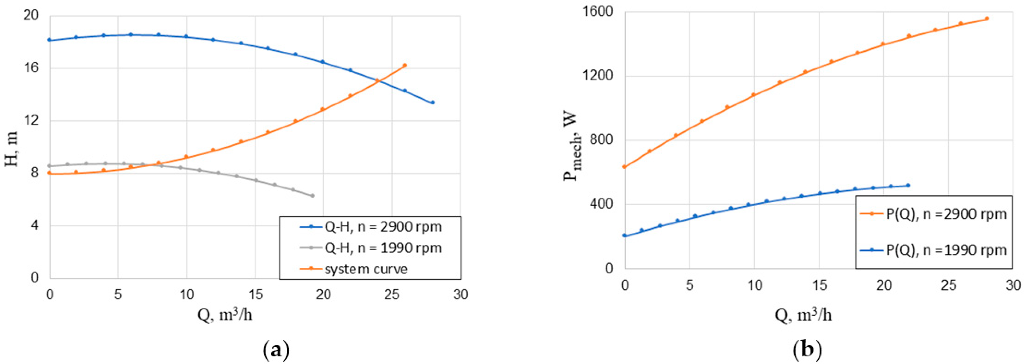
Figure 2 represents the
Q-
H characteristics and the dependencies of the shaft power on the flowrate for both pumps at the rated rotational speed. The two pumps under consideration have an identical no-load head of about 18 m but different maximum flow rates. The required maximum flow rate
Q100% = 24 m
3/h can be provided by the single pump with the rated power of 1.5 kW (
Figure 2a). When using the pumps with the rated power of 750 W, two such pumps are required to provide
Q100% = 24 m
3/h (
Figure 2b). The required mechanical power
Pmech can be calculated as
H∙Q∙g∙ρ/η
pump, where
g = 9.81 m/s
2 is the gravitational acceleration; ρ = 1000 kg/m
3 is the water density; η
pump is the pump efficiency. However, for calculations in this study,
Pmech is obtained from
Pmech(
Q) dependences from the manufacturer’s catalogue (
Figure 2c,d). The maximum required flowrates of both pumping systems were chosen to correspond to the flowrate of the pump Calpeda—B—40/12C/A at the best efficiency point (BEP)
Q100% =
QBEP1 = 24 m
3/h (
Figure 2e).
3. Operating Point Calculation for Pumps
This section briefly describes the mathematical models of the examined pumping systems. In order to assess the characteristics of the operation mode of the pumps, the graphical analysis method is used.
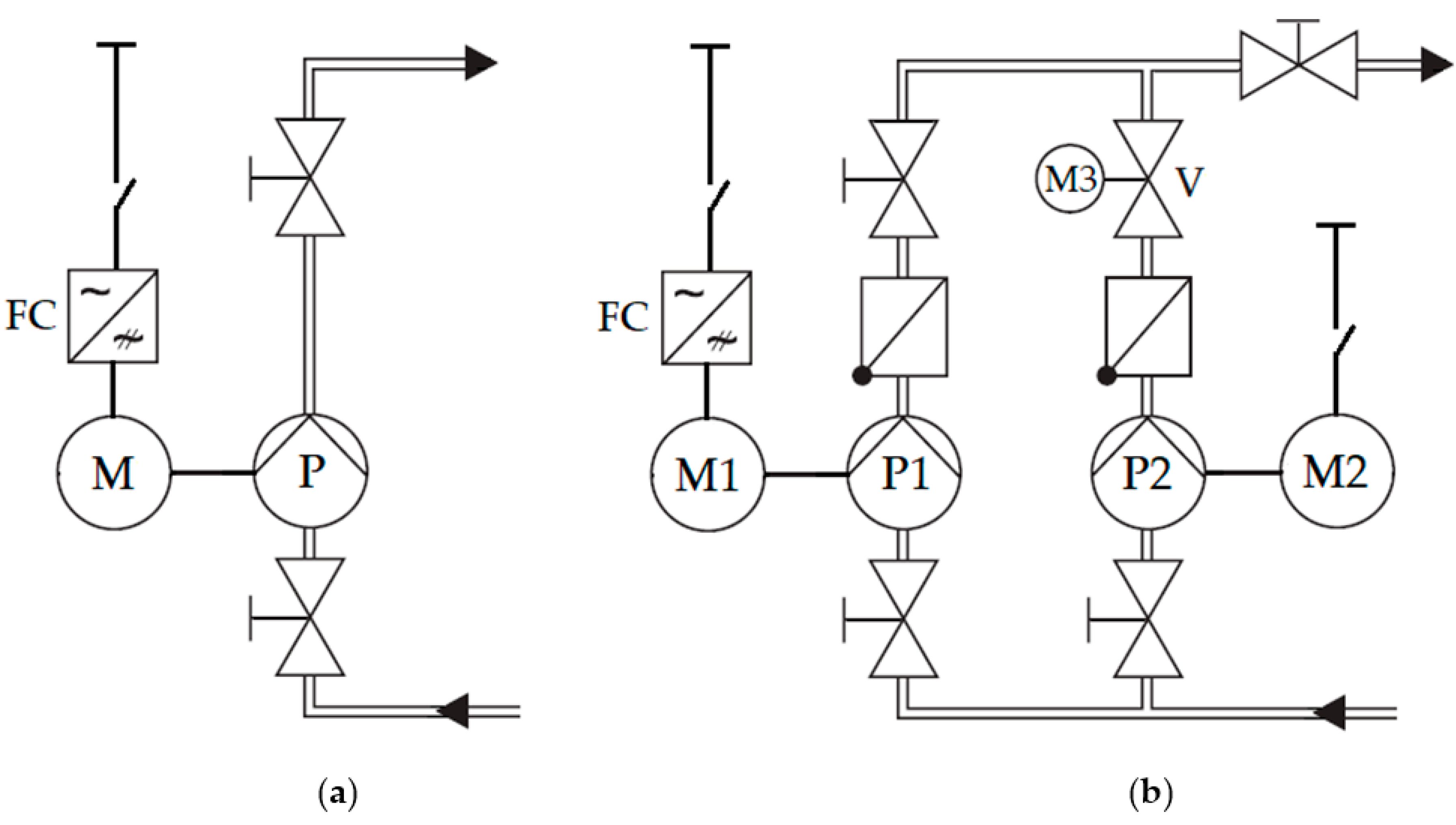
Figure 3a represents a single-pump system.
Figure 3b represents a multi-pump system. Pumps
P and
P1 are coupled with induction motors
M and
M1, respectively. Frequency converters (FC) feed these motors. Pump
P2 is coupled with induction motor
M2. The throttle
V is equipped with drive
M3 (throttle control) and when the pumps operate simultaneously, it is regulated together with the electric drive
M1. The rest of the valves shown in
Figure 3 as well as non-return valves are used for protective purposes not for control.
The values of
Q and
H of individual pumps are calculated according to their technical characteristics (
Figure 2). During the development of a mathematical model for the pump system, polynomial interpolations of the technical characteristics of the pumps are used [
8,
23]. The mathematical model of a multi-pump system consisting of two similar pumps and a hydraulic load is described by the following equations [
8,
23]:
where
Q1 and
H1 are the flowrate and the head of the variable speed controlled pump;
Q2 and
H2 are the flowrate and the head of the non-adjustable speed pump;
a = −0.02903,
b = 0.15655, and
c = 18.284 are the coefficients of the interpolation polynomial obtained according to the
Q-
H characteristics of pump Calpeda—B—NM 32/12D at the rated rotational speed (
Figure 2);
s1 and s
2 are the rotational speeds of the variable speed and non-adjustable speed pumps in relative units (
s1 =
n1/
nrate;
s2 =
n2/
nrate);
n1 and
n2 are the rotational speeds in absolute values;
nrate = 2900 rpm;
Qreq and
Hreq are the required values of the water supply and hydraulic head (hydraulic loads);
Hst and
k are the static head and the hydraulic friction coefficient of the hydraulic system.
The flowrate of separate pumps
Q1 and
Q2 and the total flowrate of the pumping system
Qreq are related according to Equation (4) [
8]:
The friction coefficient
k is defined as:
where
Hmax = 16 m,
Qmax = 24 m
3/h,
Hst = 0.5∙
Hmax [
25].
To calculate the variation of flow
Q, head
H, and power on the shaft
Pmech at different rotational speeds, the affinity laws are applied [
23]:
where
QN1,
HN1 and
PmechN1 are the flowrate, pump head, and power on the shaft at speed
N1 <
nrate;
QN2,
HN2 and
Pmech are the flowrate, pump head, and power on the shaft at speed
N2 =
nrate.
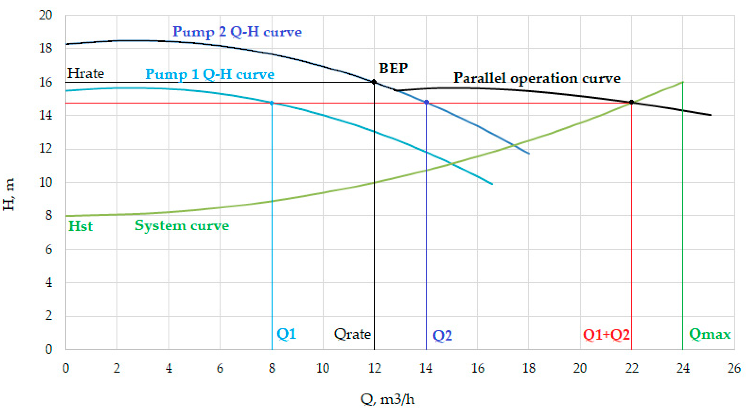
During the operation of pumps in parallel without throttling the flow
Q of pumps in the multi-pump system sums up (4) at the same hydraulic head value. Then, the intersection point of the resulting performance
H-
Q curve and system curve is obtained (
Figure 4).
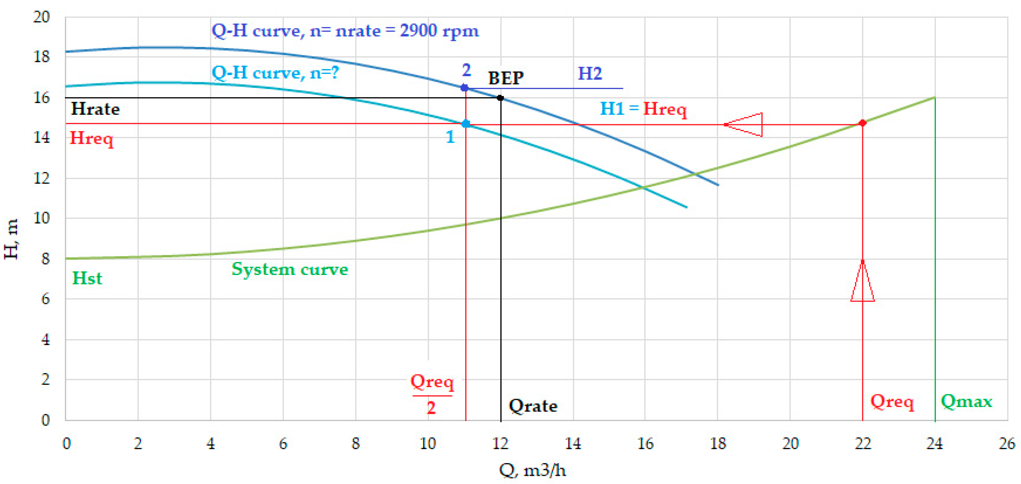
The algorithm for the graphical solution of the system of Equations (1)–(4) is explained below for parallel operation of two pumps, with one VSD. At a given value of the reference flowrate
Qreq, Equation (3) determines the required value of the head
Hreq. Since the pumps operate at different rotational speeds, to achieve the same head
Hpump1 =
Hpump2 =
Hreq, the pump capacity in the absence of throttling should be different. The speed of the second pump with non-adjustable electric drive equals the rated speed (2900 rpm); therefore,
s2 = 1. According to Equations (2) and (4), the values of
Q2 and
Q1 are obtained as follows:
To calculate the hydraulic head of the first pump, the affinity laws can be expressed in the following way (9):
From Equation (1) taking into account affinity laws (6) and (9), the following equation is derived:
The greater the difference in rotational speed between the two pumps, the greater the difference between flowrate
Q1 and
Q2. This condition leads to an overload of the non-adjustable pump and underload of the variable speed pump, which is not acceptable in terms of the energy efficiency point of view (at
Qreq less 75% of
Qmax,
Q1 becomes negative) [
8]. This article considers the parallel operation of the pumps by ensuring equal flowrates of the two pumps with the help of throttling by using throttle
M3 for the non-adjustable pump. Flowrates
Q1 and
Q2 are calculated according (11):
The control law (11) for parallel pumps is described in the literature and is widely used in practice [
8]. In this case, the pump working points will be defined as the intersection points of the pump characteristics
Qreq/2 (points 1 and 2,
Figure 5). The performance curve of the first pump (VSD) should cross point 1 with coordinates (
Qreq/2;
Hreq). The rotational speed of the first pump is determined by equation (9). The regulation throttle of the second pump (non-adjustable) is controlled to maintain
Q2 =
Qreq/2.
4. Determination of Pump Characteristics and Mechanical Power during the Operation Cycle
To determine the performances of the above-mentioned pumping systems, first, mechanical powers
Pmech are calculated, for ten different operation modes shown in
Figure 1.
Table 1 represents the calculated characteristics of the single pump system at ten different water flowrates, according to
Figure 1. In the case of the single-pump system with one variable speed pump, the working points of the pumping system move along the system curve and are defined as intersection points of
Q-
H pump characteristics at a certain rotation speed
n and the hydraulic system curve.
The curve
Q-
H and the mechanical power at a decrease in the pump rotational speed are calculated using affinity laws (6), (
Figure 6).
In the case of the joint operation, two similar pumps operate in parallel, and the total flowrate equals the sum of the flowrates of the individual pumps Q = Q1 + Q2. The first pump has an adjustable speed drive, and the rotation speed of the second pump is constant.
The range of the output flowrate can be divided into two parts:
Water flowrate regulation in the range from 0 to 60% is achieved by speed variation of the variable speed pump. A non-adjustable pump in this range of flows is not switched on and is closed by a return valve to prevent water from flowing through it in the backward direction;
Water flowrate regulation in the range from 60 to 100% is achieved by the operation of both pumps. Water is supplied by joint control of the rotational speed of the 1st pump according to the regulation law (10) and of throttling the 2nd pump. In a dynamic mode, this type of regulation can be achieved with the help of proportional-integral (PI) controllers.
In the case when the operation of the pumps in parallel is provided only by the rotation speed control of one of the pumps without throttling of a non-adjustable pump, the pump loading caused by flowrate will be different. The pump with a non-adjustable drive operating at nominal rotation speed will be overloaded and a variable speed drive will be underloaded. As the value of
Qreq decreases, the load difference will increase. If the flow rate is such that for a given speed
n1 the head
H2 approximately equals or is greater than the shut-off head of the adjustable pump, then the flowrate of a variable speed pump will be close to zero (deadheading), or even negative (reverse flow). The reduction of the total flow of pumps operating in parallel by increasing the reverse flow of one of the pumps is identical to bypass-control. However, continuous operation of the pump in such modes is unacceptable due to low energy efficiency and can lead to deterioration of the pump equipment [
2]. To avoid these operation modes, it is necessary to reduce the pressure in the pipeline connected to a non-adjustable pump with the help of throttling.
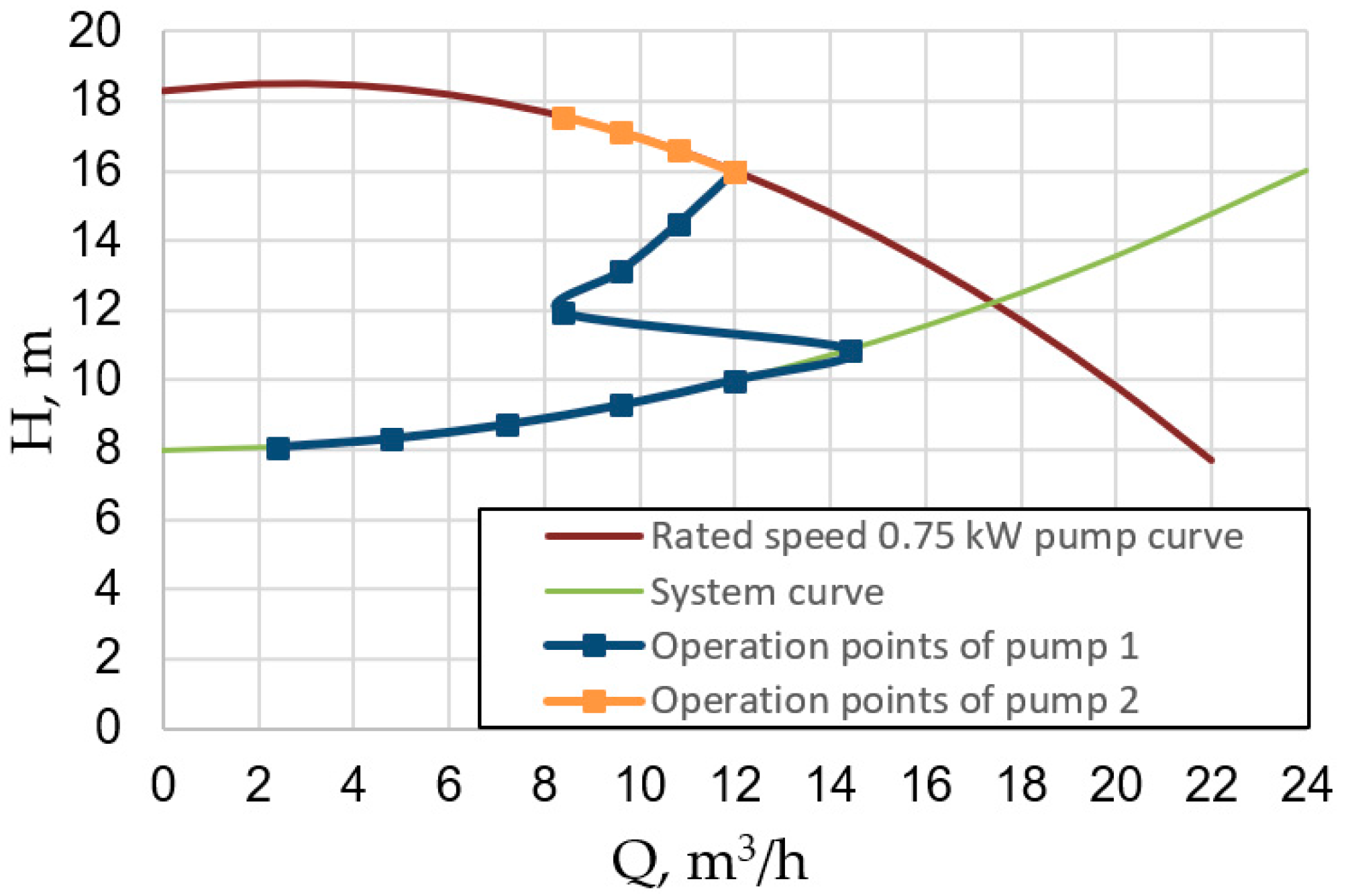
Based on the considerations given above, in the case of calculating the joint operation of two pumps in multi-pump system, the working points of the variable speed pump are determined in the same way as in the case of operation of one pump with a flow
Qreq/2 according to Equations (1)–(3). The working point of the pump with a non-adjustable drive is determined by the intersection of its
Q-
H characteristics and vertical line
Qreq/2.
Table 2 represents the calculation results for these pumps operating in parallel for ten different modes of the cycle with the selected control method
Q1 =
Q2.
Figure 7 also shows the calculated working points of these parallel pumps in terms of
Q-
H axes.
In
Table 2 the following notation is used:
Pmech1 is the mechanical power of the variable speed pump;
Pmech2 is the mechanical power of the non-adjustable pump. As can be seen from
Figure 7 and
Table 2, when using the two pumps, the second parallel pump is used only at the required flow rate of 70% or more. Flow rates in the range of 0–60% can be provided by one of the lower power pumps. When both pumps are used, the equal distribution of the required flow rate
Q1 = Q2 =
Qreq/2 between them is adopted. As mentioned above, this control law provides minimum power consumption in this case. The head values of the two pumps are not equal to each other,
H1 ≠
H2, which is achieved by throttling the output of the second pump. The speed of the first pump
n1 is adjusted by the VSD. The rotational speed of the second pump powered directly from the mains is assumed to be constant,
n2 = 2900 rpm. The
H1,
H2, and
n1 values are calculated according to the method described in
Section 3 (see
Figure 5). The mechanical powers
Pmech1 and
Pmech2 are evaluated using the
Pmeh(Q) dependence shown in
Figure 2b.
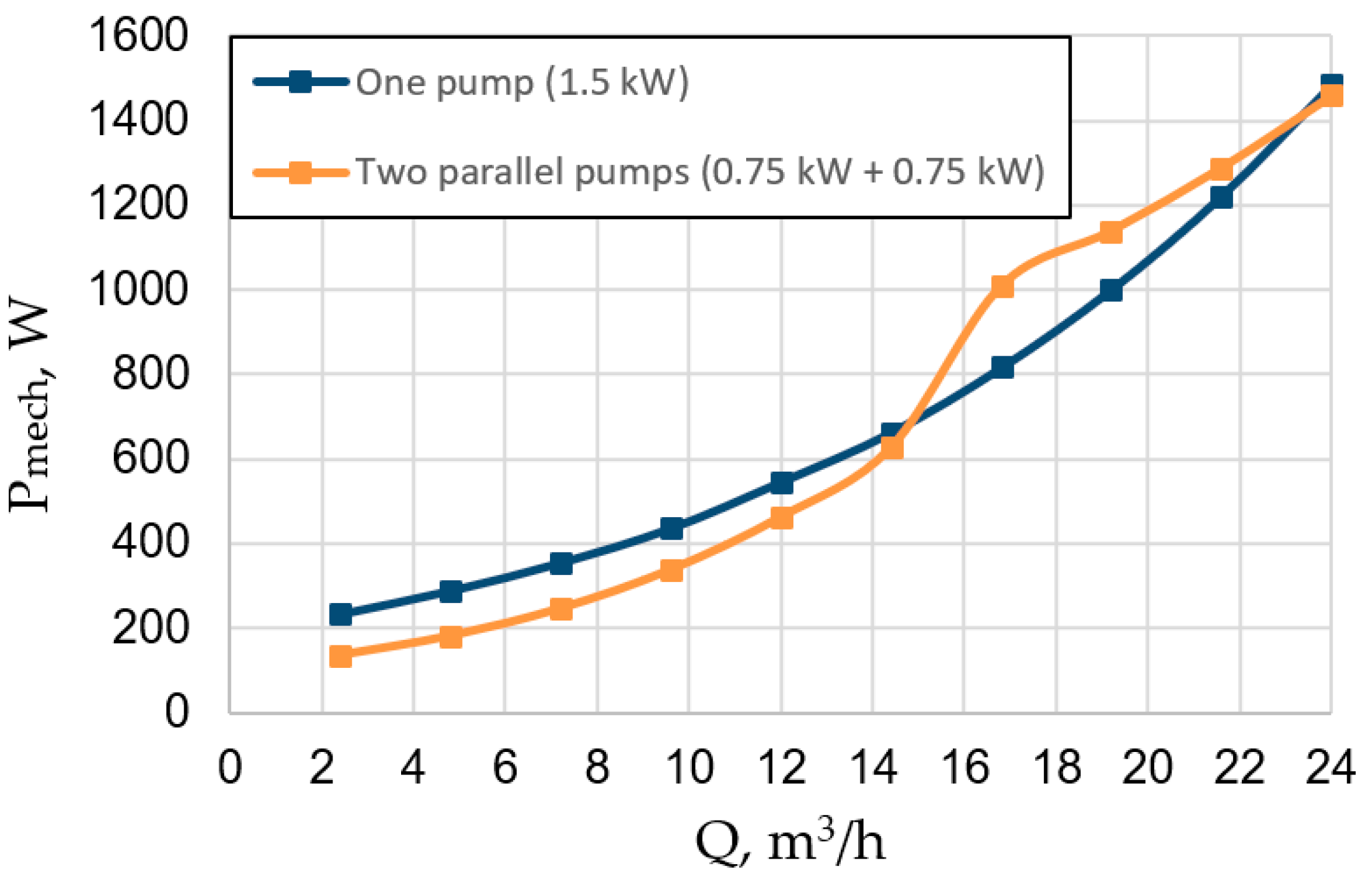
Figure 8 represents graphical dependencies of the total mechanical power of the two configurations of a pumping system on the water flowrate according to
Table 1 and
Table 2. It can be seen that during the variation of the flowrate up to
Qreq = 14.4 m
3/h (60%), the multi-pump system demands less mechanical power. At higher
Qreq, however, it requires more mechanical power than a system with a single pump.
5. Assessment of Energy Consumption of the Two Considered Pump Systems
This section is focused on the electrical energy consumption calculation for the two configurations of the mentioned pump systems: single-pump (
Figure 3a,
Table 1) and multi-pump (
Figure 3b,
Table 2). In the current simulation, it was assumed that 2-pole induction motors with rated powers of 1500 W and 750 W are used in these pumping systems. These motors have the IE3 energy efficiency level. To determine the efficiency of motors and frequency converters at the operating points calculated in the previous section, the data for seven standard modes are used (according to IEC 60034-30-2) at a certain value of
T and
n (
Table 3). Such data are used because the standard IEC 60034-30-2 [
26] requires the motor manufacturers to declare the motor efficiency in these seven operating points. Some of the manufacturers provide such data in their catalogs [
27]. The data in
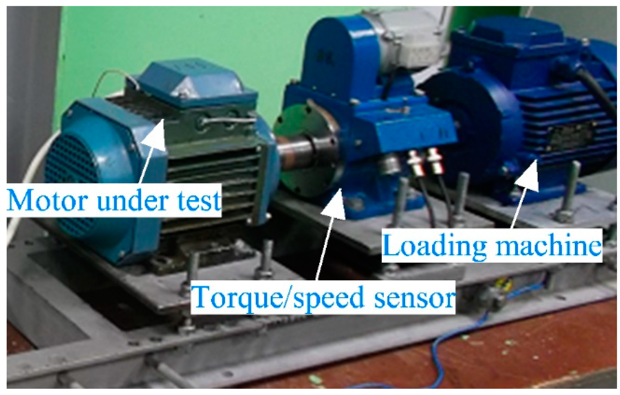
Table 3 related to the efficiency of the considered induction motors and frequency converters are obtained experimentally. These data were obtained from testing of M3AA90L2 and M3AA80B2 motors (IM-1.5 kW and IM-750 W, correspondingly, IE3-class, manufacturer ABB) [
28] powered by a frequency converter with a rated power of 1.5 kW (model Optidrive P2, manufacturer Invertek Drives) [
29]. This test was performed according to IEC 60034-2-3, Method 2-3-C: Input-output method (
Figure 9).
The values of the efficiency of motors and frequency inverters in the considered operating points (
Table 1 and
Table 2) found by the polynomial interpolation of the data in
Table 3 [
4,
30] are shown in
Table 4. The following notations are used in
Table 4: ηmotor is the motor efficiency of the single-pump system; ηconv is the frequency converter efficiency of the single-pump system; ηmotor1 is the motor efficiency of the multi-pump system for variable speed drive; η
conv1 is the frequency converter efficiency of the multi-pump system for variable speed drive; η
motor2 is the efficiency of non-adjustable motor in multi-pump system.
With the help of the obtained results from tables (
Table 1,
Table 2 and
Table 4), we can calculate the electric power consumption from the network (
P1), daily electricity consumption (
Eday), annual electricity consumption (
Eyear), total amount of annual electricity costs (
Cyear), and annual cost savings (
Syear) for the multi-pump system with low-power pumps in comparison with the single-pump system:
where
Pmech, and
ηmotor are the mechanical power and efficiency of
m-th electrical motor in the
i-th operation mode;
ηconv. is the efficiency of
m-th frequency converter in the
i-th operation mode;
t∑ is the 24 h cycle time;
ti is the duration of the
i-th operation mode;
GT = 0.2036 €/kWh is the electrical energy costs in Germany in the second quarter of 2019 for 1 kW∙h for industrial applications [
31];
Cyear 1 and
Cyear 2 are the total annual energy costs of the multi-pump system (two pumps) and single-pump (one pump) system configurations.
The results of the calculation according to Equations (12)–(16) are shown in
Table 5 and
Table 6.
Figure 10 shows the dependence of the electric power consumption by the pumping systems from the grid for the mentioned cases. The energy saving possibilities were calculated according to the data in
Table 5 (
Table 6). Thus, in the case of the multi-pump system (two parallel pumps), the energy consumption is higher in comparison with a single-pump unit, in the rare operation modes when the two pumps operate together. However, significant energy savings can be achieved in operation modes when one of the pumps of the multi-pump system can provide the required flowrate. As a result, in the case of the multi-pump system (two parallel pumps), the energy consumption during the working cycle is reduced by 29.8% in comparison with the single-pump system.


 ,
, 


