Dynamic Balance Method for Grading the Chain Drive Double Threshing Drum of a Combine Harvester


Key Laboratory of Modern Agricultural Equipment and Technology of Ministry of Education, Jiangsu University, Zhenjiang 212013, China
*
Author to whom correspondence should be addressed.
Appl. Sci. 2020, 10(3), 1026; https://doi.org/10.3390/app10031026
Submission received: 2 January 2020
/
Revised: 29 January 2020
/
Accepted: 3 February 2020
/
Published: 4 February 2020
(This article belongs to the Section Mechanical Engineering)
Abstract
:Although the individual threshing drum of a combine harvester was balanced on a dynamic balancing machine before it is assembled, there were still unbalances after multiple drums were assembled with the chain drive. In this paper, the double drums with a chain drive of a crawler combined harvester were selected as the research subject. The aim of this study was to develop a dynamic unbalance mode for grading chain drive double drums. Based on the dynamic unbalance characteristics of the main driven drum, the experimental research on the radial balance of the driven drum end face was carried out. It was known that the chain drive had a direct and obvious influence on the unbalanced phase of the drum. The unbalance of the drive load had an obvious effect on unbalanced amplitude of an active drum through the transfer characteristics of the chain drive. For the multi-stage transmission characteristics of a combine harvester, a step-by-step balanced grading chain drive double drum dynamic balancing method was practiced. Results showed that the unbalanced amplitude after balancing threshing drum I chain transmission mode of the combine harvester can be reduced by a maximum of 91%. Simultaneously, the unbalanced amplitude of threshing drum II can reduced by a maximum of 69.2%. The size and position of the wrap angle of the chain drive would directly affect the phase of the two equivalent unbalanced masses.
1. Introduction
A drum is widely used in agricultural machinery, and unbalance of a drum exacerbates the vibration and noise of the whole machine [1,2,3]. Unbalanced vibration often causes the working failure of the whole machine [4,5]. A threshing drum is the main working part of a rice combine harvester for crop threshing separation. Although it is usually balanced on the dynamic balancing machine before it is assembled, there is still unbalances after the multiple threshing drums are assembled by a chain drive [6,7,8]. The unbalanced state of a threshing drum will exacerbate the meshing vibration while chain driven [9]. The lateral vibration will generate a large dynamic load, which will aggravate the jitter of the chain.
When a combine harvester is working, the threshing drums are often unbalanced and will stimulate the frame vibration. In order to study the unbalanced vibration and excitation characteristics of the threshing drum, Gen et al., (2019) used Automatic Dynamic Analysis of Mechanical Systems to simulate the dynamic balance of the horizontal axial flow corn flexible threshing drum and improved the reliability of the whole machine by correcting the dynamic balance of the threshing system [10]. In order to effectively reduce the vibration caused by the unbalance of a spindle rotor system, Gu et al., (2019) synchronized the exciter and the two cylindrical drums in the super-resonant vibration system using the averaging method of correcting small parameters [11]. Cui et al., (2018) carried out the dynamic unbalance vibration effect analysis of the high-speed cylindrical drum bearing cage and proposed the nonlinear dynamic differential equation of this high-speed cylindrical drum bearing considering the dynamic unbalance of the drum [12]. Therefore, there is an unbalanced vibration problem during the rotation of the drum in many engineering situations. Hu et al., (2018) derived the calculation equation of the exciting force and the exciting torque by analyzing the kinematics and dynamic statics of the main drive system [13]. At present, researches on the dynamic balance of drum mainly focuses on the vibration analysis of the transmission mode, the dynamic balance modeling and the rotary device [14]. In fact, the tension on the belt, the drive chain, and the lateral vibration generated during operation will affect the vibration of the drum.
In the vast majority of agricultural machinery, the chain drive is an important way to transmit power [15,16]. The chain drive has attracted the attention of many scholars. For example, Zhang et al., (2019) introduced the step-by-step design method of sprocket parts [17]. The theoretical calculation was carried out from the sprocket shape to the tooth profile. And then, the physical design comparison was carried out to determine the appropriate cogging shape. Gong et al., (2019) analyzed the dynamic factors affecting the intermittent motion of the transmission chain system, established the dynamic equation of the transmission chain system, and then solved the equation by the modal superposition method [18]. Because the application of the normal and lateral forces generated in the chain drive depends directly on their application points, Velicu et al., (2019) proposed the kinematic modeling of the contact points between the chain sleeve and the sprocket [19]. Chai et al., (2019) studied the stability of the transmission system under the condition of multiple parallel drums. He indicated that there were interactions between adjacent drum [20]. In view of the non-uniformity in the chain drive and the large vibration shock, Song et al., (2018) established the equivalent mechanism of the transmission chain of the coal mine [21]. It is found that the link speed and acceleration show a trend of decreasing first and then increasing with the chain drive. Although the chain drive is widely used in the combine harvester, it is prone to severe meshing impact and vibration. Its lateral vibration will generate a large dynamic load, which will aggravate the lateral vibration of the chain and seriously affect the dynamic balance of the rotary device.
The drum system consists of multiple rotating shafts with the drum and housings on the shaft. Even if each drum is in equilibrium, there is often a large unbalanced state in the entire shaft when the equipment is fully installed in place. Regarding this unbalanced state, the Lagrange method is used to establish the vibration equation of the shaft system and the motion equation of the drum containing the torsional effect of the shaft system by Wang et al., (2019). He indicated that the torsional stiffness of the main shaft had a greater effect on the torsional deformation of the shaft under stable conditions [22]. Zhao et al., (2018) found that coupling had a greater impact on dynamic bearing forces through substructure methods and generalized finite element methods [23]. Aiming at the unbalanced vibration problem of the spindle drum device during high-speed cutting, Qiao et al., (2017) proposed a method for controlling the optimal influence coefficient of multi-node unbalanced vibration of flexible electric spindle [24]. Liu et al., (2019) proposed an innovative dynamic model for vibration analysis of flexible drum bearings [25]. At present, there are many researches on the balance method of multi-drum series shafting, especially methods such as mode balance method and influence coefficient method are optimized and developed relatively mature [26,27]. For the multi-drums parallel type shafting system, the balancing method needs to be changed according to the change of the transmission mode. There are fewer balancing methods for the multi-drums parallel type shafting of the application chain transmission. However, multiple threshing drums on the combine harvester were assembled by chain transmission.
In this paper, the double drum chain drive model of rice crawler combine harvester was selected as the research object. The response equation of the lateral vibration of the chain drive was established. The influence of random weighting on the unbalance of the driven drum and the unbalance effect of the driven drum on the active drum through the chain drive were studied. The equivalent unbalance of the chain drive and a multi-drum dynamic balance model were developed. For the multi-stage transmission characteristics of the combine harvester, a step-by-step balanced grading chain drive double drum dynamic balancing method was proposed and practiced.
2. Material and Methods
2.1. Double Drums Chain Grading Drive Structure Principle
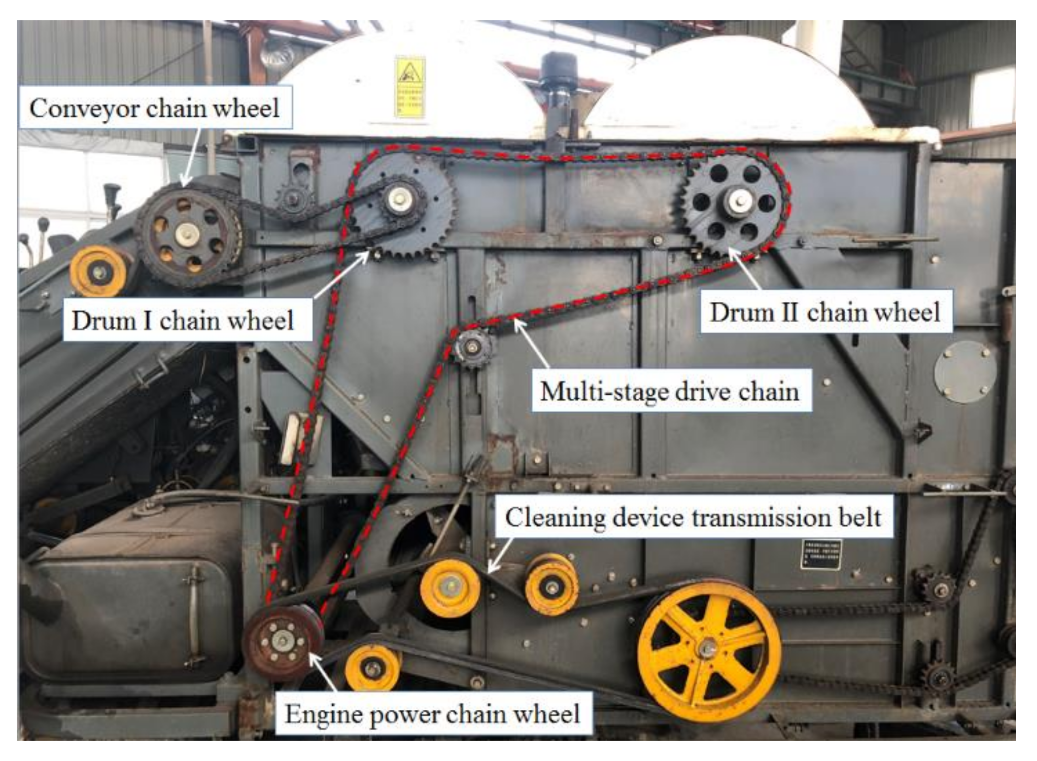
The rice crawler combine harvester is mainly composed of a conveying device, threshing drums, a cleaning fan, a vibrating screen, engine, etc. The threshing drum of the existing rice crawler combine harvester in Asia mainly has the double horizontal axial threshing drums arranged in parallel. The double threshing drums are an important part for realizing crop harvesting. In rice threshing, rice straw was sent to threshing drum I to be threshed and separated originally and then entered to threshing drum II to be re-threshed and re-separated [28,29,30]. The transmission structure of the crawler combine harvester and its double threshing drums are shown in Figure 1.
The power drive principle of combine harvester was that power was firstly output by the Engine and divided into two groups. The first set of power was transmitted to the crawler chassis gearbox to affect the crawling and steering functions. The second set of power was passed through the chain to threshing drum I, which was then passed by threshing drum I to threshing drum II and a bridge device. During the operating process, two threshing drums carried a large load and would have an unbalance state. The unbalance of the double threshing drums often seriously affected the performance and service life of combine harvester.
2.2. Unbalance Vibration Modeling of Grading Chain Drive Double Drums
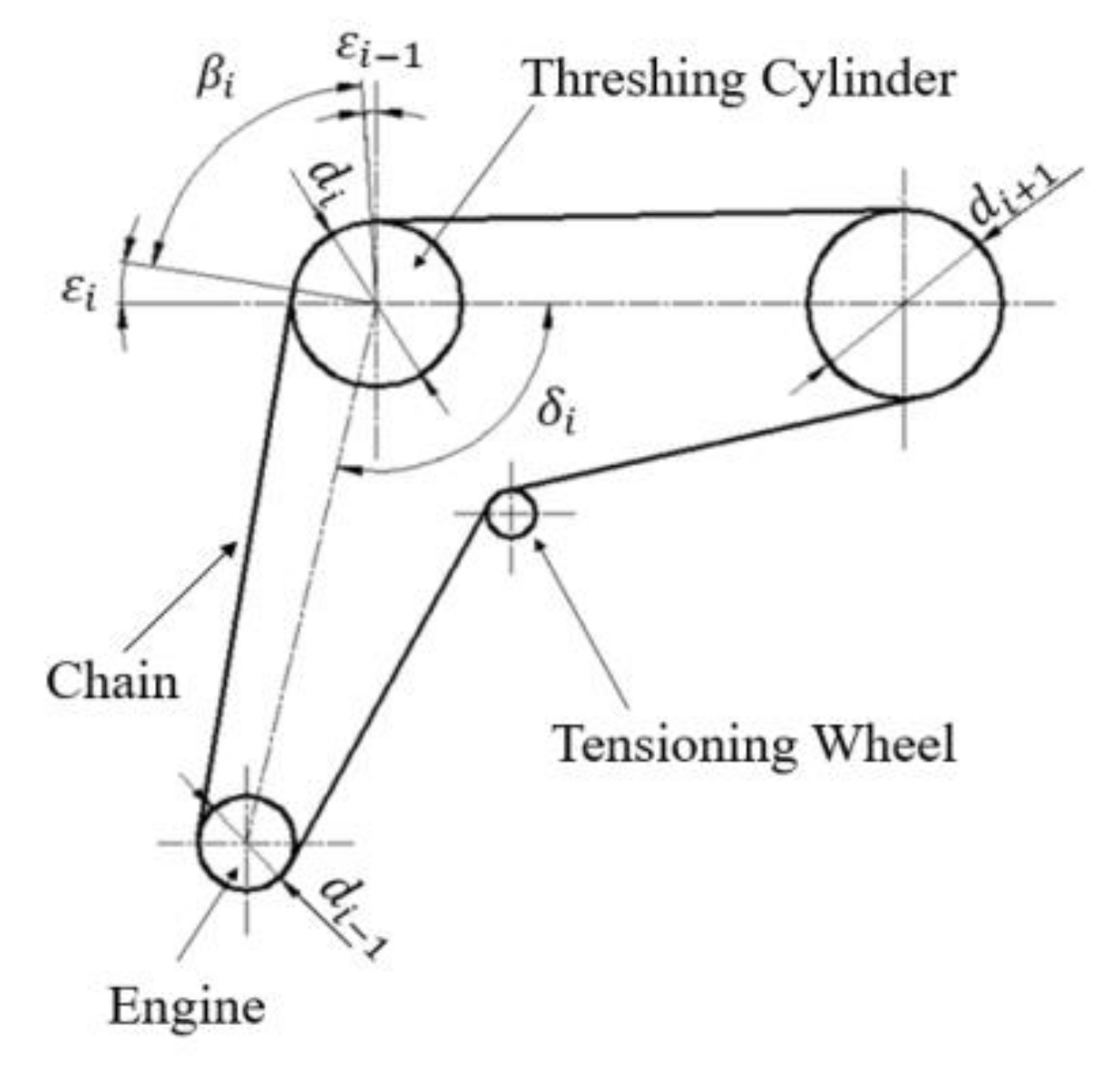
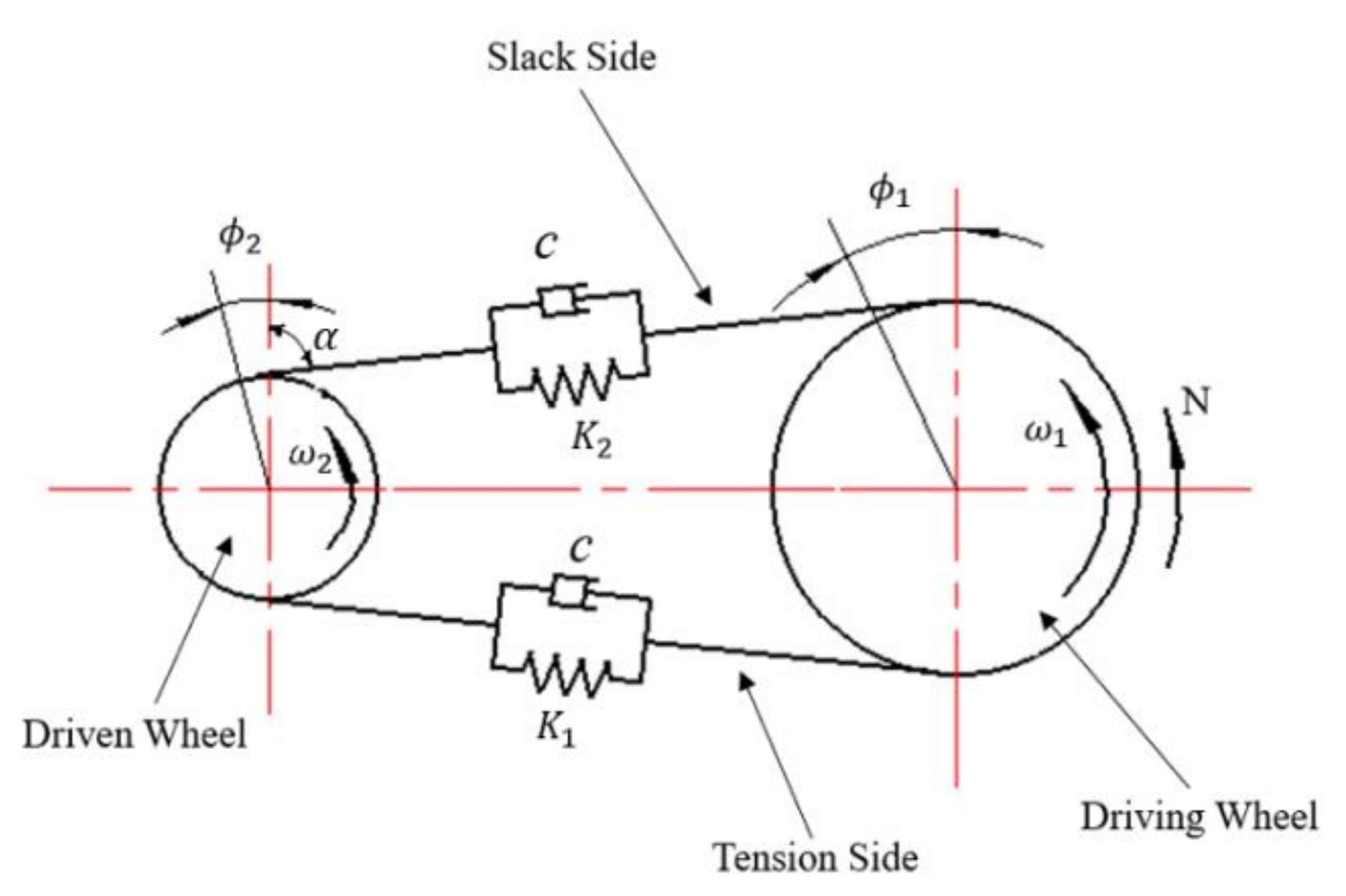
There was still an unbalance vibration after threshing drums was assembled by chain transmission [31,32,33]. The double threshing drums would affect each other through the chain drive during operation. Based on the above problem, the transverse double threshing drums of rice crawler combine harvester were used as test prototype in the paper. The double threshing drums chain drive structure and drive model were shown in Figure 2. In order to further simplify the complex problem, the transverse vibration model of the chain drive was established. The differential equation of motion was derived to find the natural frequency and the excitation response when the threshing drum was unbalanced or eccentric. Schematic diagram of the transverse vibration model of the chain drive was shown in Figure 3.
As shown in Figure 2 and Figure 3, sprocket 1 is the driving wheel, sprocket 2 is the driven wheel; k1 and k2 are spring stiffness of tight and loose edges of chains, respectively; c is damping coefficient; m is driven wheel mass; r1 and r2 are radius of the pitch circle of the main and driven wheels, respectively; J1 and J2 are moment of inertia of main and driven wheels around their respective axes, respectively; ω1 and ω2 are theoretical speed of the main and driven wheels, respectively; Φ1 and Φ2 are the angle at which the main and driven wheels turned, respectively; α is the angle between the drive chain and the vertical line connecting the center of the two sprocket wheels; e is the eccentricity of the driven wheel; and N is the rotational torque that drove the driving wheel 1 to rotate.
The lateral vibration of chain drive referred to the up and down direction vibration that occurred when the chain moved axially in the chain drive plane [34,35,36]. As shown in Figure 2, when the driven wheel was in the equilibrium position and its wheel center was used as the origin of the coordinate system, at any time t, the kinetic energy T and the potential energy V of the chain drive lateral vibration model system were as followed, respectively.
Considering the effect of damping, the virtual power δω made by the external force and damping force of the system according to the virtual work principle was as followed.
Let , , , . Then:
The following results can be obtained by differentiating Equations (4) and (5).
According to the principle of virtual power and Lagrange Equation, the differential Equation of system vibration can be obtained as followed.
where, the , , and , was displacement vector, velocity vector, and acceleration vector, respectively; the M, C, K, and F were the mass matrix, damping matrix, stiffness matrix, and external force matrix (incentive matrix) of the system, respectively. Obviously, these were all symmetric matrices. Their expressions were as follows:
In order to simplify the model, the torsional vibration generated by the driving wheel was not considered. That was ; ; , then ; ; . Because of , the lateral differential vibration model system of the chain drive model could be simplified. The differential Equation of motion of the two-degree-of-freedom vibration system was as followed.
where , , , and .
The natural frequency of chain drive lateral vibration model system was one of the inherent properties of the transmission system. It was usually determined by the structure, material, shape and other parameters of the system. It was less affected by damping and external excitation force.
2.3. Dynamic Balance Principle and Method
The central idea of the threshing drums balance principle is to eliminate the excess inertial centrifugal force by weighting or de-weighting, so that the resultant force is zero. After determining the position and size of the threshing drums imbalance, a certain quality can be removed by punching or the like at the position to eliminate excess centrifugal force. In the opposite direction, the weight is increased by welding, adding a gasket.
So that the centrifugal force generated by the weighting and the centrifugal force generated by the original unbalanced mass of the threshing drums can cancel each other. Base dynamic balance equation of rigid threshing drums, then:
where u(z) is random space vector, Wi is correction amount in the x and y directions, and zi is the axial coordinate of the correction amount.
In Equation (10), the first equation in the dynamic equilibrium equation is the force balance equation. The second equation is the force couple equilibrium equation. It can be known from the equations that there was a unique solution only when N = 2. Regardless of the initial unbalance of the threshing drums u(z) in any plane and direction, the dynamic balance can be performed by weighting or de-emphasizing in any two selected correction planes. The dynamic balance equation did not require the axial position of the correction amount. That was, the change in the axial distance had little effect on the change in the amount of imbalance.
Based on this, the rigid threshing drum was often balanced with a single correction surface or a double correction surface. The single correction surface was weighted or de-weighted on a correction surface of the threshing drum to ensure that the residual unbalance of the drum during rotation was lower than the allowable residual unbalance specified by the dynamic balance level standard. It was mainly applicable to disc parts and shaft parts. The double correction surface was weighted or de-weighted on the two correction surfaces of the threshing drum to ensure that the residual unbalance of the threshing drum during rotation was lower than the allowable residual unbalance specified by the dynamic balance level standards. It was suitable for all rigid threshing drum.
The threshing drums can be divided into a rigid drum and a flexible drum [37,38]. The rigid threshing drums referred to a type of drum whose working speed was much lower than the first-order critical speed of the rotor itself. The flexible threshing drums referred to a drum whose working speed was close to or higher than the first-order critical speed. When such threshing drums were dynamically balanced, it was often necessary to consider the effect of flexural deformation on rotor balance.
2.4. Balance Method Test Bench for Grading Chain Drive
Test Method for Dynamic Balance Characteristic
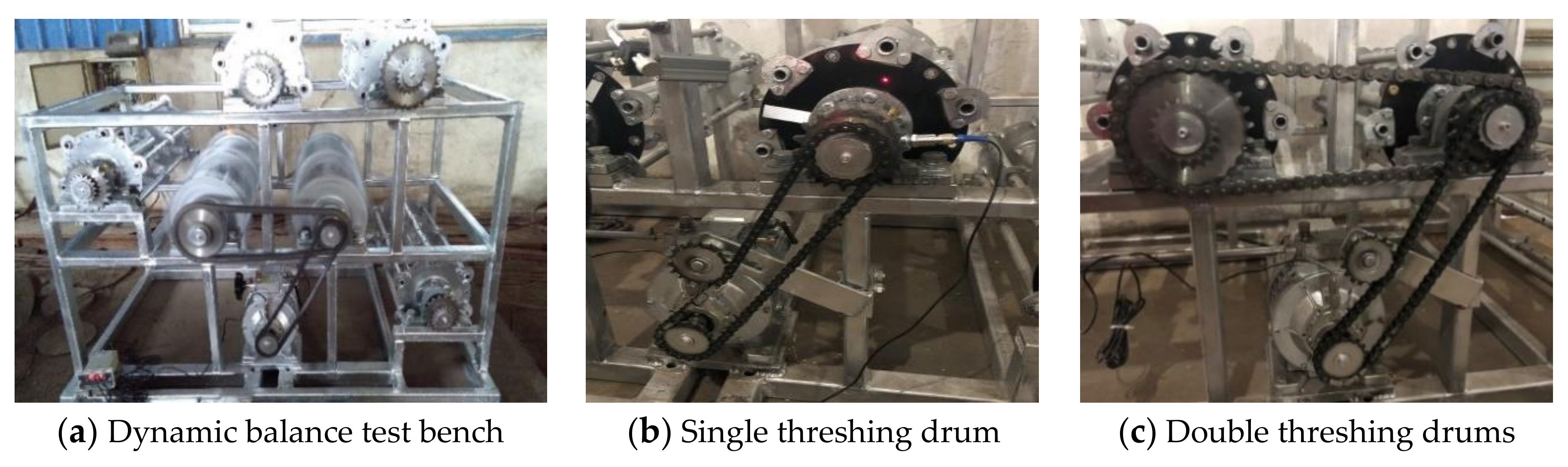
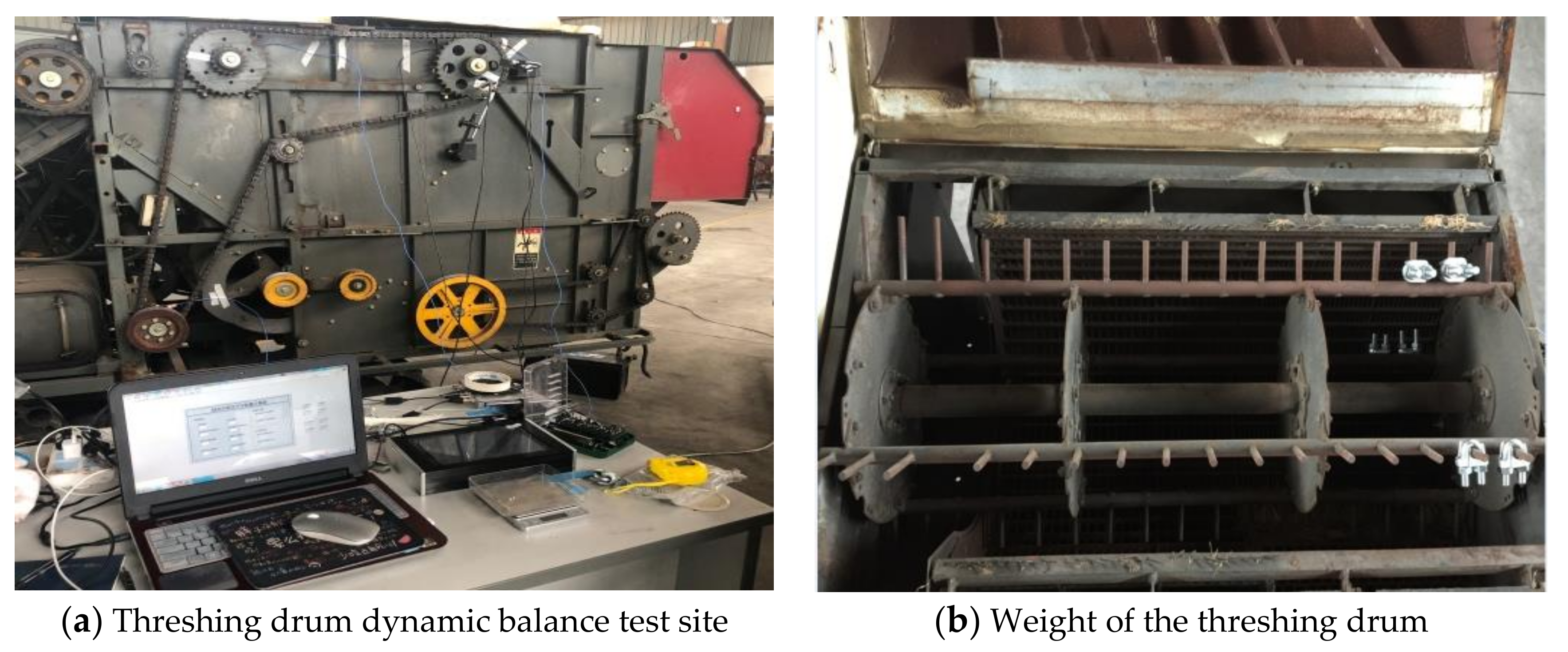
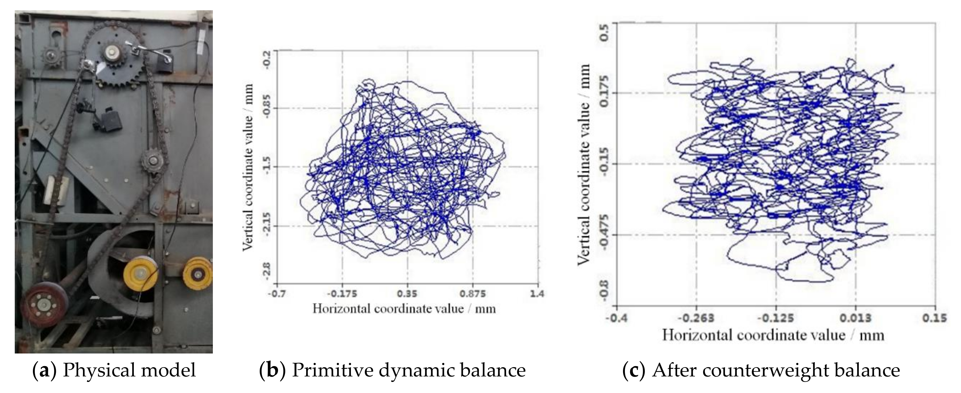
The combined harvester has many excitation sources. The transmission path also is complicated. The power needed to be transferred from the Engine to the threshing drum after multiple transmissions. There were too many interference factors on the way. It was not convenient to study the chain drive on the whole combine harvester. So, the threshing drum and its power transmission path were separately extracted in this paper. The characteristic test of the graded chain drive double threshing drums was carried out on the threshing drum dynamic balance test bench to minimize the interference of external influence factors on the test results. The structure of double threshing drums dynamic balance test bench was shown in Figure 4a.
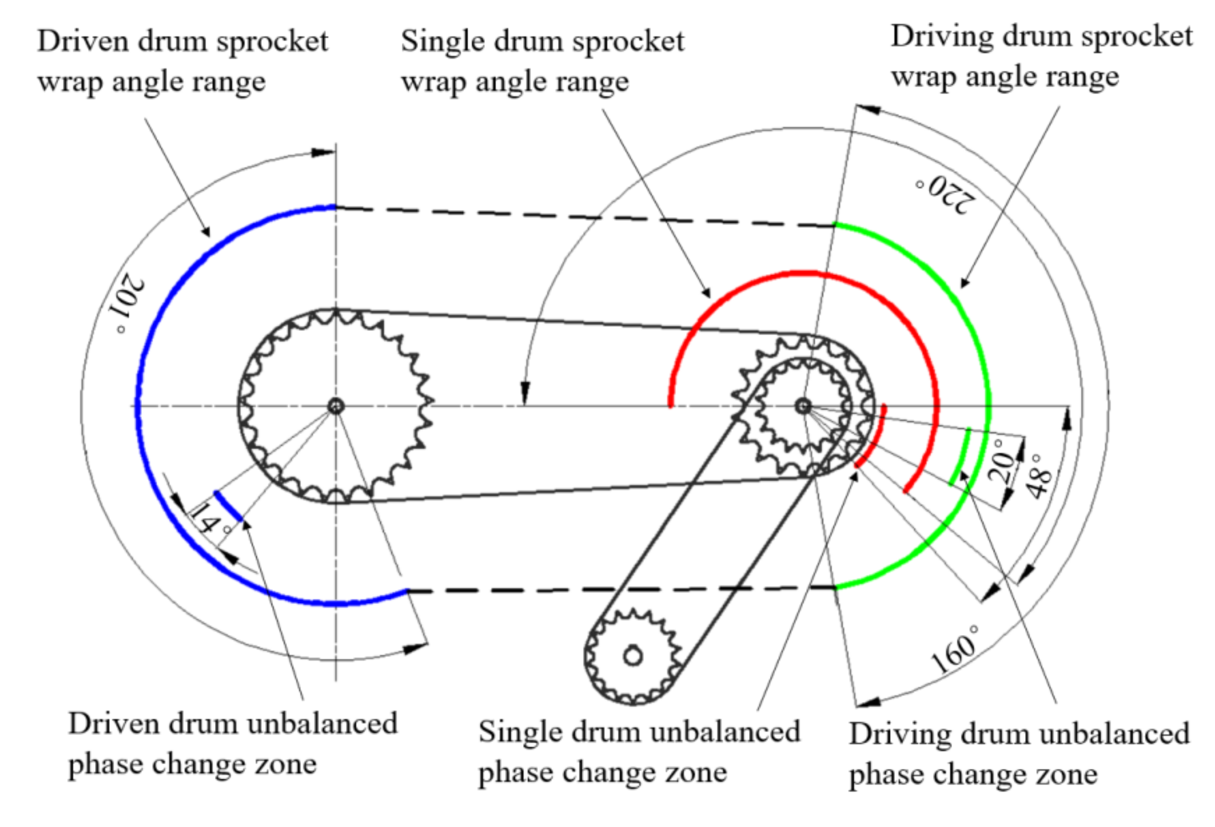
In order to investigate the effects of transfer characteristics, the layout and transmission path of the threshing drum on the combine harvester were simulated. The unbalanced amount of each drum at different speeds was measured under two different conditions of single drum and double drum. The single threshing drum and double threshing drum experiment were performed shown in Figure 4b,c. In the case of a single threshing drum, the angle of the small sprocket was 180°~40°. In the case of double threshing drum, the angle of the large sprocket of the active drum was 280°~80°, and the angle of the large sprocket of the driven drum was 69°~270°.
As shown in Figure 4, the threshing drums dynamic balance test bench was 1390 mm long, 974 mm wide and 1006 mm high. It was equipped with 6 threshing drums driven by a chain drive. The overall frame was smooth, making it easy to use the magnetic table to install various sensors for online dynamic balance testing. The test bench can simulate various working conditions of the threshing drum. Each side of the threshing drum was equipped with sprocket of the same specification, which can realize double-sided transmission. Different sizes of sprockets were installed between threshing drum I and threshing drum II. The speed also can be adjusted from 0 to 1000 rpm by controlling the motor. The size of the threshing drum was 240 mm in diameter and 612 mm in length. Threshing drum was scaled according to the size of the conventional threshing drum on the combine harvester. A plurality of counterweight holes was opened in the radial direction and the axial direction of the threshing drum to facilitate the addition of a counterweight during the test. There were 6 counterweight holes on both sides of the threshing drum, which were evenly distributed at an angle of 60° for the radial weight of the end face. There was a toothed rod in the middle of each of the two end weight holes, each of which had 10 weight holes. There were 5 weight holes between the two sides of the disk and the intermediate plate, which were separated by 50 mm for axial weighting of the end faces. All counterweight holes on the drum were 8.5 mm in diameter.
2.5. Engineering Application of Double Drum Balance of Combine Harvester
Combine Harvester Double Threshing Drum Dynamic Balance
Taking the Word Dragon’s double threshing drums combine harvester as the research object, the transmission of threshing drum I and threshing drum II were driven by Engine. The scene layout of the threshing drum dynamic balance test was shown in Figure 5a.
A single correction surface was selected for both threshing drums. A unidirectional vibration acceleration sensor and a photoelectric rotation speed sensor were arranged on one side of the threshing drum transmission surface. A reflective strip (phase zero mark line) was attached to the web of the threshing drum to adjust the position of the photoelectric sensor so that the spot of the sensor can be hit. In the test, the portable dynamic balancer was used to calculate the equivalent unbalance of the chain drive. The balance was performed by adding a weight on the correction surface of the threshing drum, as shown in Figure 5b.
The initial dynamic balance of the driven drum was required before the relevant test to minimize the initial unbalance of the drum, so as to be as close as possible to the absolute equilibrium state and reduce interference to subsequent tests. The rotation speed of the threshing drum was usually 600~1000 rpm. Considering the diameter of the drum, the type of structure, the layout order, etc., it would be applicable to different rotation speeds. Many models had realized that the rotation speed of the threshing drum was adjustable, and the speed adjustment range was up to 300~1200 rpm. Combined with the adjustable range of the test bed and the transmission ratio, the final selected active drum balance speed was 700 rpm, and the driven drum rotated at 500 rpm [39].
2.6. Test Method for Vibration Characteristics and Axis Trajectory
2.6.1. Grading Chain Drive Double Drum Vibration Characteristic Test
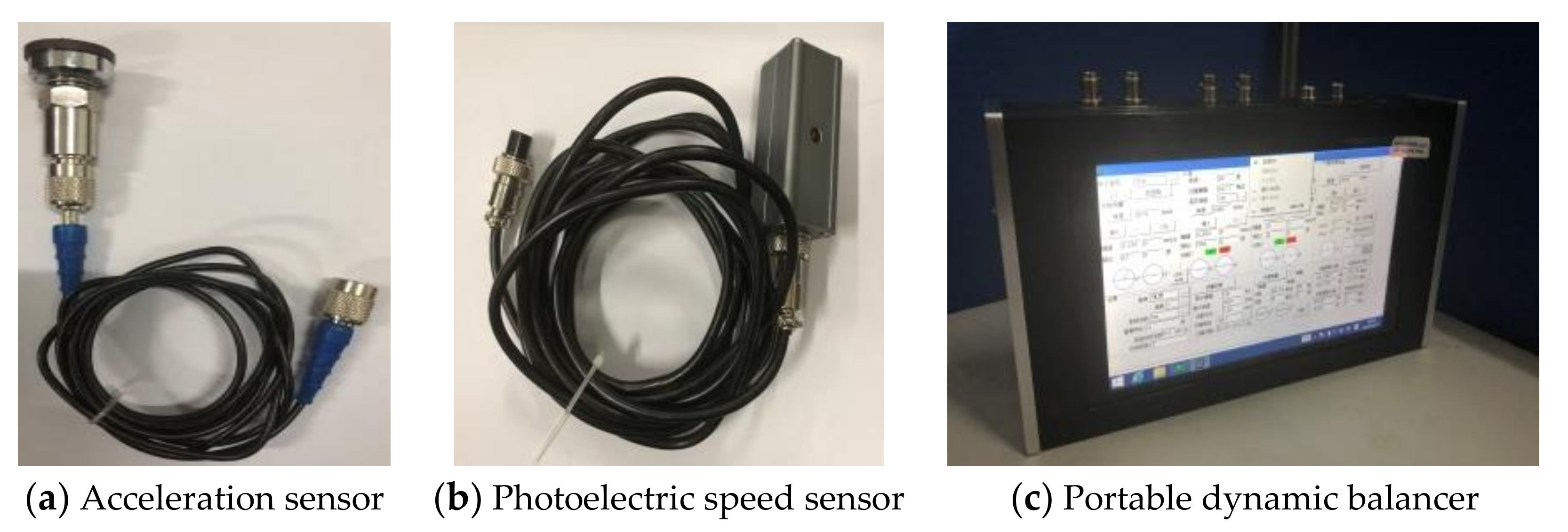
Based on the transmission characteristics of the chain drive, the equivalent unbalance of the chain drive and the model of double threshing drums dynamic balance were tested. A S956Y-1 portable dynamic balancer (manufactured by Beijing Sundege Technology Co., Ltd., Beijing, China), and a vibration acceleration sensor and a photoelectric speed sensor were used to test dynamic balance. The test instruments were shown in Figure 6.
The main performance parameters of the S956Y-1 portable dynamic balance instrument (manufactured by Beijing Sundege Technology Co., Ltd., Beijing, China) and vibration acceleration sensor and photoelectric speed sensor were shown in Table 1.
The balance state of the threshing drum is affected by the transmission. The transmission relationship of the drum is mostly located on one side. There are fewer transmission relations on both sides. In order to better study the influence relationship between the transmission and the balance state of the drum, select a single calibration surface and use the side with the transmission relationship as the detection and correction surface.
2.6.2. Axis Trajectory of Double Threshing Drum Test
Eddy current sensors are widely used in large-scale rotating mechanical shaft vibration and axial trajectory testing. Compared with the contact measurements, they have wide measuring range and strong anti-interference ability. Eddy current sensors can collect various parameters of vibration more accurately. The eddy current sensor used for the axis trajectory test of the axial threshing cylinder was shown in Figure 7a.
The eddy current sensors are produced by Chinese Donghua Testing Company (Jingjiang, China) (5E106 eddy current sensor). It mainly consist of a magnetic probe, an extension cable and a preamble. The performance index and technical parameters of 5E106 eddy current sensor were shown in Table 2.
Two eddy current sensors were arranged perpendicular to each other at the axial end of the threshing drum by magnetic base. Two sensors were used to measure the horizontal and vertical displacement of the threshing drum. By synthesizing the signals measured by the sensors, the axis trajectory curve could be obtained. The Figure 7b showed the axial trajectory test site of the threshing drum.
3. Results and Discussion
3.1. Dynamic Balancing Method of Driven Drum
As shown in Figure 4, in the dynamic balance test of the driven drum, the initial unbalance of the driven drum was measured to have a magnitude of 1.234 mm/s and a phase of 159°. Therefore, it was necessary to add a test weight of 82.03 to 164 g. A test weight of 107.7 g and whose angle 90° were added. After the test was aggravated, the amplitude of the unbalance was 0.562 mm/s and the phase was 204°. Therefore, it was suggested to add a test weight of 143.4 g, whose angle was 115°. Then, a test weight of 142.45 g and whose angle 120° were added. The residual unbalance was measured to have amplitude of 0.37 mm/s and a phase of 161°. The amplitude was reduced by 70% and the highest standard G 0.4 of the balance level ISO1940 was reached.
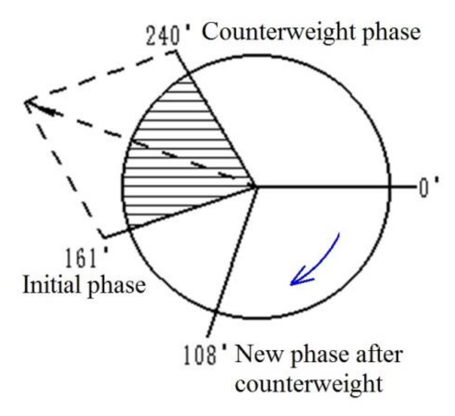
Based on the results above, a mass of 58.8 g was added in the direction of 240° of the drum, which artificially caused the drum to be unbalanced. It can be obtained by the vector parallelogram rule. The angle of the unbalance after the weighting was between the initial unbalanced phase 161° and the emphasis phase 240°. However, at the same rotational speed, the phase of the unbalanced amount after the actual measurement was 108°. The phase relationship was shown in Figure 8. It can be seen that the side chain drive affected the unbalanced state of the threshing drum from this phase change.
3.2. Driven Drum End Surface Radial Weight Dynamic Balance Effects
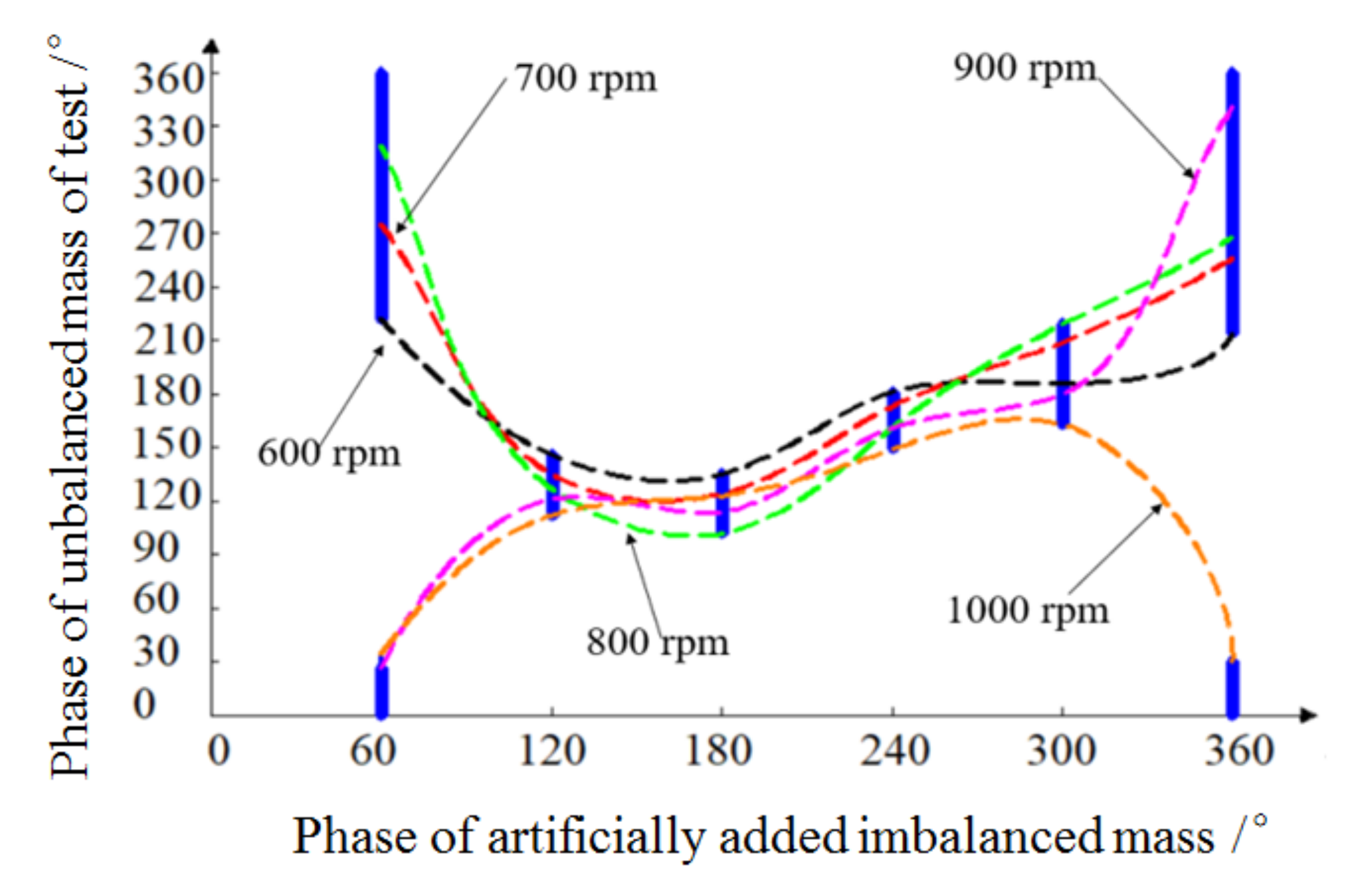
As shown in Figure 4, the driven drum end surface radial weight dynamic balance was tested. The mass of 161.3 g was added to the weight holes in the 60°, 120°, 180°, 240°, 300°, and 360° directions of the end of the threshing drum. The unbalance amount of the threshing drum was measured at different rotation speeds. The test data was shown in Table 3.
Since the threshing drum rotated counterclockwise, the chain drive was loose on the upper side and the tight side was on the lower side. There was a chain pulling force on the sprocket on the tight side. The loose side had a certain impact force on the sprocket. Especially when the transmission chain was not tight enough, the lateral vibration of the chain was obvious. These forces were all acted on the rotating shaft through the transmission system, which was equivalent to the chain drive exerting a series of imbalances of different sizes and phases on the rotating shaft. The phase change area was shown in Figure 9.
Because the chain drive affected the drum within the wrap angle to varying degrees, the drum was unbalanced. The unbalance was non-uniform and varied in size. Therefore, all the unbalances generated in the chain transmission process were equivalent to two unbalanced quantities, which were the unbalance of the tight edges and the loose edges. At the same time, the size and position of the wrap angle of the chain drive would directly affect the phase of the two equivalent unbalanced masses.
The vibration generated by the chain drive at the critical point of the wrap angle was large. So the phase of the element with a large force near the two critical points was taken as the phase of the equivalent unbalance amount. Li et al., (2016) had shown that as the drum speed increases, the frequency of the lateral vibration of the transmission increased and the amplitude decreased [40]. With the increase of the tension, the frequency of the lateral vibration of the transmission did not change and the amplitude decreased. Changes in the tension of the drive chain and the change in the speed of the barrel were subject to changes in the lateral vibration of the chain drive. That was to say, the magnitude of the equivalent unbalance would vary, which caused the phase of the chain drive unbalance to always change within the wrap angle, rather than being constant.
Therefore, the unbalanced phase region was always within the wrap angle range or overlapped with the wrap angle range as shown in Figure 9. This was a good explanation for why the emphasis phase was not always in the unbalanced phase region after the emphasis. In addition, the weighting block was added in the direction of 60° and 360°, which was within the wrap angle range, and the range of the unbalanced phase region was large. The weighting block was added in the direction of 120°, 180°, 240°, and 300°, which was just outside the wrap angle range, and the range of unbalanced areas was small. Through the radial weight test, it can be found that the chain drive had a direct and significant influence on the unbalanced phase of the threshing drum. This conclusion was also applicable in other fields. Ren et al., (2018) collected data and preprocessed the online condition monitoring system of the wind turbine drive train, which indicated that influence of the wind turbine drive chain on the online comprehensive condition monitoring and fault diagnosis system [30].
3.3. Active and Driven Drum Dynamic Balance Effects
Based on the active and driven drum dynamic balance test based on transfer characteristics, the layout and transmission path of the threshing drum on the combine harvester were simulated. The unbalanced amount of each drum at different speeds was measured under two different conditions of single drum and double drum. The experimental data was shown in Table 4.
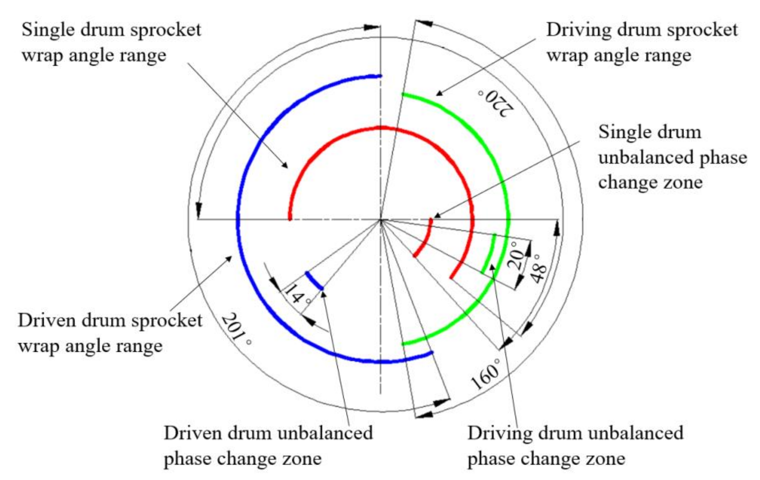
According to test results, it was found that the unbalanced phase of the drum produced different degrees of change after the new drum was connected in parallel. However, it was always within the wrap angle of the sprocket as shown in Figure 10.
When a drum had two sprocket wheels with a transmission relationship at the same time, that was one drum had two transmission paths, the drum unbalanced phase appeared as a sprocket wrap angle range that was biased toward the dominant segment. As shown in Figure 10, the unbalanced amount of the driven drum had a complicated influence on the unbalanced amplitude of the active drum through the transmission characteristic of the chain drive. The active drum unbalance amplitude sometimes increased and sometimes decreased. The variation of the fluctuation was large, but in general, the unbalance of the driven drum had less influence on the unbalanced amplitude of the active drum.
The driven drum was connected to the active drum through the chain drive, which can be equivalent to the load of the active drum. So that the transmission chain between the two drums generated tensile force and lateral vibration, which had obvious influence on the unbalanced phase of the active and driven drum. And the unbalanced phase of the drum was always within the wrap angle of the sprocket in the driven drum end surface radial weight balance test. Taking into account the above two points, when constructing the double threshing drums dynamic balance model, the influence of the chain drive on the unbalanced phase would be considered. The influence of the transmission characteristics on the unbalanced amplitude would not be considered.
3.4. Double Threshing Drum Grading Chain Drive Dynamic Balance
After the active drum was loaded, the chain drive between the load and the active drum had a greater influence on the unbalanced phase of the active drum, which was mainly caused by the tension of the tight side of the chain and the lateral vibration of the loose edge. It was equivalent to adding two imbalances on the active drum. The contact area between the chain and the sprocket was the entire wrap angle range. The tensile force on the chain and the action area of the lateral vibration were respectively a circular arc in the sprocket wrap region, rather than a single point of action. These forces were non-uniform and different in size on the arc. In order to solve the effect of the force, this paper proposed the concept of equivalent unbalance. The forces at all positions were concentrated to two points of action. The magnitude of the two forces can be determined to form the same effect formed by the respective component forces. Two equivalent unbalances were formed.
The phase of the equivalent unbalance amount may be selected according to the actual situation. The phase of the sprocket with a large force near the two critical points of the sprocket wrap angle range was taken as the phase of the equivalent unbalance amount. The general method of calculating the amplitude of the equivalent unbalance amount was as follows.
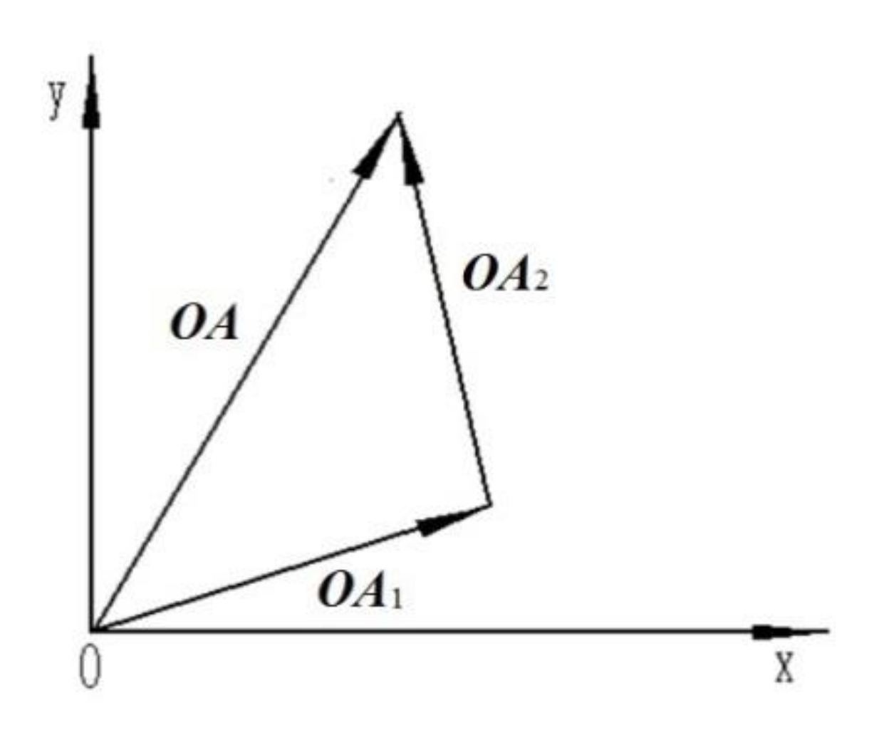
As shown in Figure 4, the driving drum was provided with two sprockets. And the driven drum was provided with a sprocket. The equivalent unbalance of the small sprocket in the chain drive was vector OA (Coordinate value is xA, yA). Tight edge equivalent unbalance was OA1. Equilibrium equivalent unbalance was OA2. And then OA1 + OA2 = OA. The vector sum relationship was shown in Figure 11.
Equivalent unbalance of large sprocket was vector OB (Coordinate value is xB, yB). Tight edge equivalent unbalance was OB1. Equilibrium equivalent unbalance was OB2. And then OB1 + OB2 = OB. Unbalanced amount of the drum itself was vector OC (Coordinate value is xC, yC). The actual unbalance amount when the load was driven by the chain drive was vector OD (Coordinate value is xD, yD). Then:
OA + OB + OC = OD
As shown in Table 4, in the case of the active drum rotation speed of 700 rpm and the driven drum rotation speed of 500 rpm, the unbalanced amplitude of the active drum in the single drum mode was 0.712 mm/s and the unbalanced phase was 10°. So the unbalanced amount of the active drum itself was vector OC (Coordinate value is 0.701, −0.124). In the double threshing drums mode, the active drum drove the driven drum through the chain drive. The unbalanced amplitude of the active drum was 0.783 mm/s. At this time, the unbalanced phase was 20°. So, unbalanced phase was vector OD (Coordinate value is 0.736, −0.268). Since the small sprocket on the active drum was connected to the motor and was the power input end, the unbalance caused by the small sprocket can be regarded as a part of the unbalance of the active drum itself. The large sprocket was connected to the driven drum, and the unbalance amount was vector OB. So the relationship of the unbalance amount on the active drum was vector OB + OC = OD. Then:
The large sprocket wrap angle of the active drum ranged from 280° to 80°. In combination with the actual situation, the phase of the sprocket with a large force near the critical point of the wrap angle was selected as the phase of the equivalent unevenness. Therefore, choose 80° as the phase of the tight side unbalance and 320° as the phase of the unbalanced amount. The amplitudes were LB1 and LB2, respectively. So vector OB1 = (LB1 cos 280°, LB1 sin 280°), vector OB2 = (LB2 cos 40°, LB2 sin 40°). That was:
The coordinates of OB1, OB2, OC, and OD were substituted into Equations (12) and (13).
That was, the chain drive equivalent unbalance on the side of the active drum large sprocket was vector OB (Coordinate value is 0.035, −0.149). The unbalanced amplitude was 0.153 mm/s and the unbalanced phase was 77°. Generally speaking, the higher the rotation speed, the greater the chain vibrated. And also the force on the chain would change. The change of the sprocket wrap angle would also change the force phase of the sprocket, that was, the calculation of the equivalent unbalance of the chain drive was affected by the speed and wrap angle. Therefore, in order to obtain the accuracy of the equivalent unbalance of the chain drive, it was recommended to calculate the equivalent unbalance amount at the working speed and recalculate the equivalent unbalance amount when the transmission path changes.
Double threshing drums were connected in parallel by the chain drive. The transmission characteristics based on the chain drive or the influence of the load on the unbalanced phase would affect the equilibrium state of the entire system. Therefore, the dynamic balance method of the double threshing drum step chain transmission can be determined on this basis. Based on the above modeling of the chain drive excitation response and analysis of a series of experimental data, the unbalance of the load had little effect on the unbalanced amplitude of the active drum through the transmission characteristics of the chain drive. After the load was driven, the transmission chain between the load and the driving drum generated a tensile force and a lateral vibration, which had an obvious influence on the unbalanced phase of the main driven drum. Therefore, when determining the double threshing drums dynamic balance method, the influence of load and chain drive on the unbalanced phase of the active drum would be considered. The influence of the transmission characteristics of the chain drive on the unbalanced amplitude of the active drum would not be considered.
When determining the dynamic balance method of the double threshing drums of the grading chain drive, the main idea was multi-stage transmission and step-by-step balance. The double threshing drums combination of the multi-stage transmission was broken up. The balanced drum was regarded as a whole. The load was added step-by-step, and the balance was performed step-by-step, as shown in Figure 12.
In order to balance the multi-threshing drums, some of the drive chains needed to be removed. The drum connected to the power input end was used as the active drum. The amount of unbalance was measured and dynamic balancing was performed. The remaining unbalance was used as the unbalance of the active drum itself in the multi-drums system OC. According to Equation (11), combined with the active drum chain drive equivalent unbalance OA, OB, the weight of the active drum, was calculated. The chain drive between the driven drum and the active drum was then installed. It was started up and checked for whether the unbalance of the active drum met the requirements and then measured the unbalanced amount of the driven drum as its own unbalance OC. In the same way, the counterweight was calculated for the driven drum. Thus, the dynamic balance of the double threshing drums combination can be completed.
3.5. Double Threshing Drums Dynamic Balance Test Verification
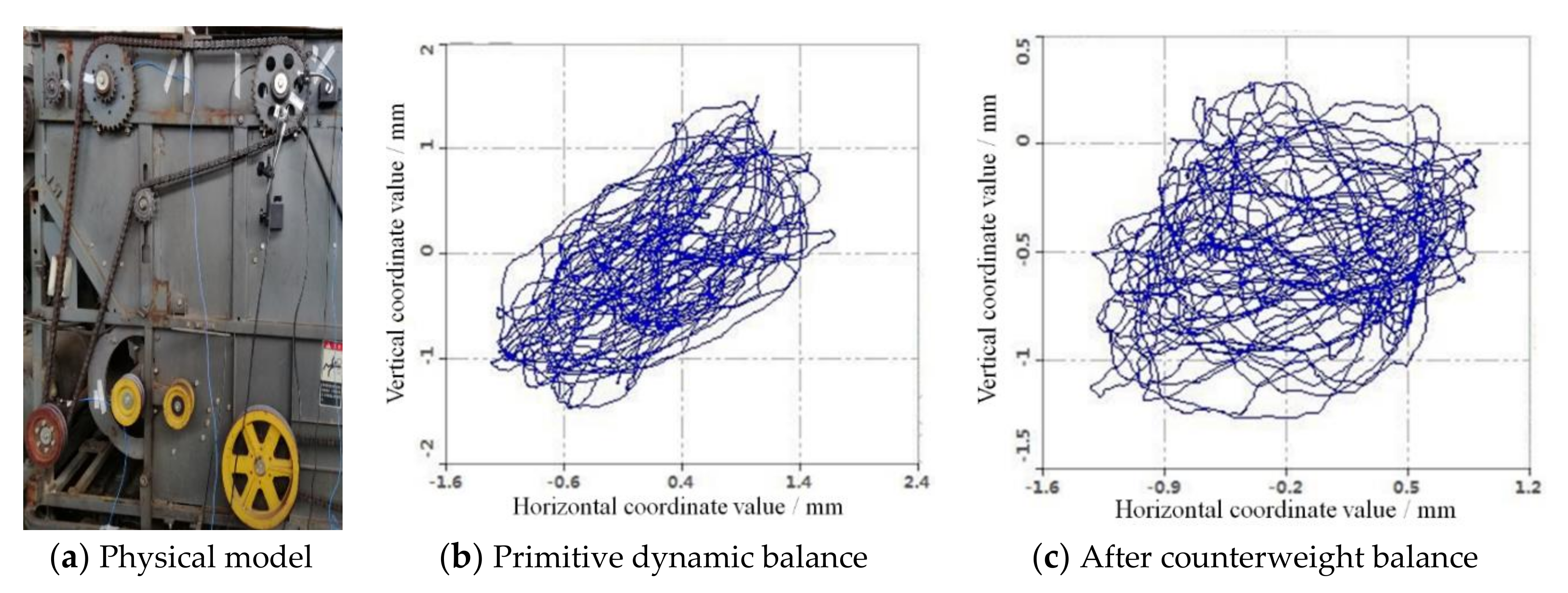
As shown in Figure 5, the double threshing drums dynamic balance verification was tested with the Word Dragon’s double threshing drums combine harvester. The transmission of threshing drum I and threshing drum II were driven by the Engine, which fit the transmission mode of this paper. The double threshing drums dynamic balance test firstly balanced threshing drum I with a balance speed of 810 rpm, and the transmission path was shown in Figure 5a. The single drum mode was selected in the portable dynamic balancer system. The initial unbalance amount of threshing drum I was 1.96 mm and the phase was 9.6°. It was recommended to add a weight of 68 g when the phase was 194°. There were 65.4 g of weight actually added in the direction of 180°. The remaining unbalance was 0.42 mm, the phase was 14°, and the amplitude was reduced by 79.5%. The original dynamic balance axis trajectory of the single threshing drum I and the axis trajectory after weighting were plotted as shown in Figure 13.
As shown in Figure 13, the original dynamic balance axis trajectories of the single threshing drum I was similar to round cake. The horizontal and vertical amplitudes of the axis trajectory were 1.70 mm and 1.34 mm, respectively. However, the axial trajectory of single threshing drum I was reduced after increasing the weight. The horizontal and vertical amplitudes coordinate values of the axis trajectory were significantly reduced, which are 0.38 mm and 0.39 mm, respectively. The amplitude of the axis trajectory was similar to the vibration amplitude.
In the portable dynamic balancer system, the double threshing drums mode was selected. The unbalance mass of the threshing drum I was measured. The initial unbalance mass (the remaining unbalanced mass after the first balance) was 0.42 mm in amplitude and 13.4° in phase. Enter the coordinates of the equivalent unbalance of the chain drive, and calculate the total unbalance amount as the amplitude of 2.36 mm and the phase of 28.2°. The amplitude was significantly increased, that was the chain drive exacerbated the dynamic unbalance of the drum. After this test, it was recommended to add a weight of 103 g whose phase was 184.9°. Actually, added a 107.5 g of weight in the direction of 180°. The residual unbalance was 0.2 mm. The phase was 32.8°, and the amplitude was reduced by 91.5%.
Then, threshing drum II was dynamically balanced, and its equilibrium rotation speed was 810 rpm. The unbalance mass of threshing drum II was measured in the single drum mode of the portable dynamic balancer system. The initial unbalance amount was 3.86 mm in amplitude and 36° in phase. It was recommended to add a weight of 137.7 g whose phase was 258°. Actually, 270 g of weight was added in the direction of 141°. The residual unbalance was 1.18 mm, the phase was 34°, and the amplitude was reduced by 69.2%. The original dynamic balance axis trajectory of single threshing drum II and the axis trajectory after weighting were plotted as shown in Figure 14.
As shown in Figure 14, the horizontal and vertical amplitudes of the axis trajectory were 3.71 mm and 2.42 mm, respectively. However, the axial trajectory of double threshing drum II was reduced after increasing the weight. The horizontal and vertical amplitudes coordinate values of the axis trajectory were significantly reduced, which were 2.02 mm and 1.63 mm, respectively. It can be seen from the above that the test results of the whole combine machine on the spot were remarkable, and the unbalanced amplitude of the drum can be reduced by 69%~91% after dynamic balancing. The double threshing drums dynamic balancing method of multi-stage transmission and step-by-step balance were effective, which greatly reduced the fundamental frequency vibration of the drum and improved the running state of the drum.
The power of double threshing drums of the rice crawler combine harvester was output by the Engine and was sequentially transmitted to threshing drum I and threshing drum II. The chain drive of double threshing drums was tensioned by the tensioning wheel. The longitudinal vibration and lateral vibration of the chain drive were the main sources of excitation for the chain drive. Longitudinal vibration had a great influence on the uniformity of chain motion and transmission, while lateral vibration affected the smoothness of the chain drive and produced meshing impact. The unbalance of the threshing drum would exacerbate the meshing vibration during the chain transmission. And the lateral vibration would generate a large dynamic load, which would aggravate the jitter of the chain edge and result in unbalance of the plurality of threshing drums during operation. Since the vibration of the entire chain drive process was extremely complicated, and the lateral vibration of the driving chain was an important cause of the unbalance induced by the transmission system resonance. According to the characteristics of the chain drive, the two sides of the chain were simplified as springs and dampers. This was why the unbalanced amplitude of the drum can be reduced by 69%~91% after dynamic balancing.
4. Conclusions
- (1)
- In the dynamic balance test of the driven drum, a mass of 58.8 g was added in the direction of 240° of the drum, which artificially caused the drum to be unbalanced. The angle of the unbalance after the weighting was between the initial unbalanced phase 161° and the emphasis phase 240°. At the same rotational speed, the phase of the unbalanced amount after the actual measurement was 108°. It can be seen that the side chain drive affected the unbalanced state of the threshing drum from this phase change. The size and position of the wrap angle of the chain drive would directly affect the phase of the two equivalent unbalanced mass.
- (2)
- When double threshing drums were connected in parallel by the chain drive, the transmission characteristics based on the chain drive or the influence of the load on the unbalanced phase would affect the equilibrium state of the entire system. The unbalance of the load had little effect on the unbalanced amplitude of the active drum through the transmission characteristics of the chain drive. After the load was driven, the transmission chain between the load and the driving drum generated tensile force and lateral vibration, which had an obvious influence on the unbalanced phase of the main driven drum. Therefore, when determining the double threshing drums dynamic balance method, the influence of load and chain drive on the unbalanced phase of the active drum would be considered.
- (3)
- In the portable dynamic balancer system, the unbalanced amplitude after balancing threshing drum I chain transmission mode of combine harvester can be maximum reduced 91%. The axial trajectory of single threshing drum I was reduced after increasing the weight. When threshing drum II was dynamically balanced, the unbalanced amplitude of threshing drum II can be maximum reduced 69.2%. The horizontal and vertical amplitudes coordinate values of threshing drum II axis trajectory were significantly reduced. When constructing the double threshing drums dynamic balance model, the influence of the chain drive on the unbalanced phase should be considered.
Author Contributions
Conceptualization, Z.T.; Methodology, Z.T. and X.L. (Xin Liu); Validation, X.L. (Xiyao Li) and H.R.; Formal Analysis, X.L. (Xiyao Li) and B.Z.; Data Curation, X.L. (Xiyao Li) and X.L. (Xin Liu); Investigation, H.R., X.L. (Xin Liu), and B.Z.; Writing—Original Draft Preparation, Z.T. and X.L. (Xiyao Li); Writing—Review & Editing, Z.T.; Supervision, Z.T. All authors have read and agreed to the published version of the manuscript.
Funding
This research work was supported by the National Natural Science Foundation of China (51705212), Jiangsu Province “Six Talents Peak” High-level Talent Project (GDZB-085), Open Fund of Jiangsu Key Laboratory of Agricultural Equipment and Intelligent High Technology (JNZ201912) and Jiangsu Province University Students Practical Innovation Training Program Project (201910299211Y).
Conflicts of Interest
The authors declare no conflict of interest.
Data Availability
The data used to support the findings of this study are available from the corresponding author upon request.
References
- Li, K.Z. Analysis, diagnosis and prevention of common faults in agricultural machinery. Sci. Technol. Innov. 2019, 23, 140–141. [Google Scholar]
- Yang, X.; Tian, M.Q.; Li, L.; Song, J.C.; Zhang, L.F.; Wu, J.K. Noise reduction method for vibration signal driven by mining belt conveyor. Ind. Autom. 2019, 45, 66–70. [Google Scholar]
- Li, Z.; Miao, F.; Yang, Z.; Wang, H. An anthropometric study for the anthropomorphic design of tomato-harvesting robots. Comput. Electron. Agric. 2019, 163, 104881. [Google Scholar] [CrossRef]
- Cui, Y.C.; Deng, S.E.; Zhang, W.H.; Chen, G.D. The impact of roller dynamic unbalance of high-speed cylindrical roller bearing on the cage nonlinear dynamic characteristics. Mech. Mach. Theory 2017, 118, 65–83. [Google Scholar]
- Xing, C.H.; Li, Y.L.; Zhang, L. Effective application of rotor unbalance fault in diagnosis. Equip. Manag. Maint. 2019, 11, 175–176. [Google Scholar]
- Wang, Z.; Tu, W.; Zhang, K.; Shi, Q.H.; Li, J.; Wei, C.Y. Research status of dynamic balance method for high speed spindles. Modern Manuf. Eng. 2019, 6, 154–160. [Google Scholar]
- Li, Z.Z.; He, L.D.; Zhang, L.H.; Zhang, Z.C.; Wan, F.T. Experimental study on low-speed dynamic balance of two-span four-supported shaft rotor. J. Beijing Univ. Chem. Technol. Nat. Sci. Ed. 2019, 46, 65–71. [Google Scholar]
- Kang, J.; Yuan, Y.; Liu, H.; He, J.; Jiang, M.; He, P. Load control of threshing cylinder of small-sized harvester based on current detection. Eng. Agric. Environ. Food 2017, 10, 150–156. [Google Scholar] [CrossRef]
- Tang, Z.; Zhang, H.T.; Zhou, Y.P. Unbalanced Vibration Identification of Tangential ThreshingCylinder Induced by Rice Threshing Process. Shock Vib. 2018, 2018, 1–14. [Google Scholar] [CrossRef] [Green Version]
- Gen, D.Y.; He, K.; Wang, Q.; Jin, C.Q.; Zhang, G.H.; Lu, X.F. Design and experiment of horizontal axial flow corn flexible threshing device. Trans. Chin. Soc. Agric. Mach. 2019, 50, 101–108. [Google Scholar]
- Gu, D.; Zhang, X.; Zhang, J.; Liu, Y.; Wen, B. Synchronization and coupling dynamic characteristics of an exciter and two cylindrical rollers in a vibrating system. J. Sound Vib. 2019, 456, 353–373. [Google Scholar] [CrossRef]
- Cui, Y.; Deng, S.; Niu, R.; Chen, G. Vibration effect analysis of roller dynamic unbalance on the cage of high-speed cylindrical roller bearing. J. Sound Vib. 2018, 434, 314–335. [Google Scholar] [CrossRef]
- Hu, W.T.; Liu, Y.X. Optimization of mechanical high-speed fine-punching maneuver balance. Forg. Technol. 2018, 43, 83–88. [Google Scholar]
- Li, J.; Xue, K.P.; Yang, Z.; Hong, T.S. Nonlinear control of lateral vibration of freight chain in orchard. Trans. Chin. Soc. Agric. Mach. 2017, 33, 66–72. [Google Scholar]
- Robert, T.; Niels, B.; Ulrich, G.; Elmar, W. Experimental investigations of the internal friction in automotive bush chain drive systems. Tribol. Int. 2019, 140, 105871. [Google Scholar]
- Awwaluddin, M.; Hastuty, S.; Petrus, Z.; Putut, H.S.; Edi, S.; Nugroho, A. Chain and Sprocket Analysis of Control Rod Drive Mechanism of HTGR Experimental Power Reactor. J. Phys. Conf. Ser. 2019, 1198, 022053. [Google Scholar] [CrossRef]
- Zhang, W.X.; Ren, X.Q. Optimization design of sprocket entity in synchronous chain drive. Spec. Equip. Electron. Ind. 2019, 48, 63–65. [Google Scholar]
- Gong, H.C. Dynamic analysis of intermittent transmission chain system. Mech. Transm. 2019, 43, 131–133, 143. [Google Scholar]
- Velicu, R.; Săulescu, R.; Gavrilă, C.C. Kinematic Modelling of Contact Point between Chain Bush and Sprocket. IOP Conf. Ser. Mater. Sci. Eng. 2019, 514, 012029. [Google Scholar] [CrossRef]
- Chai, L.P.; Yu, J.F.; Li, Y. Pressure pulsation characteristics in series-parallel centrifugal pump with unequal blade pitch. J. Drain. Irrig. Mach. Eng. 2019, 37, 752–757. [Google Scholar]
- Song, M.W.; Chai, M.J. Equivalent mechanism and motion analysis of roller chain based on MATLAB coal mine. Coal Technol. 2018, 37, 304–307. [Google Scholar]
- Wang, Y.L.; Zeng, Y.; Xu, L.K. Shafting vibration model with torsion deformation in shaft of hydro-turbine generator units. J. Drain. Irrig. Mach. Eng. 2019, 37, 782–787. [Google Scholar]
- Zhao, Y.; Ru, R.T.; Wu, L.Y. Study on coupling vibration characteristics of double gearbox transmission system. Mech. Transm. 2018, 42, 1–6. [Google Scholar]
- Qiao, X.; Hu, G. Active Control for Multinode Unbalanced Vibration of Flexible Spindle Rotor System with Active Magnetic Bearing. Shock. Vib. 2017, 2017, 1–9. [Google Scholar] [CrossRef] [Green Version]
- Liu, J.; Tang, C.; Shao, Y. An innovative dynamic model for vibration analysis of a flexible roller bearing. Mech. Mach. Theory 2019, 135, 27–39. [Google Scholar] [CrossRef]
- Bin, G.F.; Zhou, W.; Wang, W.M.; Li, X.J. Study on virtual dynamic balance of turbomachinery multi-rotor axis based on dynamic response analysis. J. Vib. Shock 2017, 36, 8–12, 28. [Google Scholar]
- Bin, G.F.; Li, X.J.; Chen, L.F.; Cui, Y.H. Effect of rotor unbalance on vibration characteristics of two-span three-supported shafting system. J. Power Eng. 2017, 37, 699–703, 725. [Google Scholar]
- Tang, Z.; Li, Y.; Cheng, C. Development of multi-functional combine harvester with grain harvesting and straw baling. Span. J. Agric. Res. 2017, 15, 202. [Google Scholar] [CrossRef] [Green Version]
- Tang, Z.; Li, Y.; Li, X.Y.; Xu, T.B. Structural damage modes for rice stalks undergoing threshing. Biosyst. Eng. 2019, 186, 323–336. [Google Scholar] [CrossRef]
- Liang, Z.; Xu, L.; De Baerdemaeker, J.; Li, Y.; Saeys, W. Optimisation of a multi-duct cleaning device for rice combine harvesters utilising CFD and experiments. Biosyst. Eng. 2020, 190, 25–40. [Google Scholar] [CrossRef]
- Tang, Z.; Zhang, H.; Zhou, Y.; Li, Y. Mutual Interference and Coupling Response of Multicylinder Vibration among Combine Harvester Co-Frame. Shock. Vib. 2019, 2019, 1–14. [Google Scholar] [CrossRef]
- Su, S.H.; Liu, Z.W. Hydraulic performance of guide vane mixed-flow pump based on loading distribution. J. Drain. Irrig. Mach. Eng. 2018, 36, 1233–1239. [Google Scholar]
- Wang, C.; Cui, Y.; Ge, S.; Sun, M.; Jia, Z. Experimental Study on Vortex-Induced Vibration of Risers Considering the Effects of Different Design Parameters. Appl. Sci. 2018, 8, 2411. [Google Scholar] [CrossRef] [Green Version]
- Lai, Z.N.; Yang, S.; Wu, P. Speed-throttling combined optimization for high reliability in parallel centrifugal pump system. J. Drain. Irrig. Mach. Eng. 2018, 36, 1205–1210. [Google Scholar]
- Wang, Z.; Yue, F.; Wang, H.; Gao, H.; Fan, B. Refined Study on Free Vibration of a Cable with an Inertial Mass Damper. Appl. Sci. 2019, 9, 2271. [Google Scholar] [CrossRef] [Green Version]
- Pan, D.; Fu, X.; Qi, W. The Direct Integration Method with Virtual Initial Conditions on the Free and Forced Vibration of a System with Hysteretic Damping. Appl. Sci. 2019, 9, 3707. [Google Scholar] [CrossRef] [Green Version]
- Ma, J.; Liu, T.; Zha, C.; Song, L. Simulation Research on the Time-Varying Meshing Stiffness and Vibration Response of Micro-Cracks in Gears under Variable Tooth Shape Parameters. Appl. Sci. 2019, 9, 1512. [Google Scholar] [CrossRef] [Green Version]
- Ren, Y.; Zhang, K. Integrated condition monitoring and fault diagnosis technology for wind turbine drive-train. J. Drain. Irrig. Mach. Eng. 2018, 36, 613–616. [Google Scholar]
- Xie, H.R.; Jin, C.Q.; Yin, X.; Qian, Z.J.; Teng, Y.J.; Yu, C.X. Vibration test and analysis of tracked soybean combine harvester. J. Agric. Mech. Res. 2019, 41, 158–163, 174. [Google Scholar]
- Li, Z.G.; Chen, N.X.; Shi, Y.C. Experimental study on lateral vibration law of PL-type multi-ribbed belt. J. Changchun Univ. 2016, 26, 1–4. [Google Scholar]
Figure 1.
Double threshing drums structure and chain drive diagram of the combine harvester.

Figure 2.
Double threshing drum chain drive structure and model.

Figure 3.
Chain drive transverse vibration model schematic and diagram.

Figure 4.
Double threshing drums dynamic balance test bench and chain drive mode combination.

Figure 5.
Word Dragon’s double threshing drums combine harvester.

Figure 6.
S956Y-1 Portable dynamic balancer.

Figure 7.
Axis center trajectory test method and sensors.

Figure 8.
Unbalanced phase relationship diagram.

Figure 9.
Threshing drum end face radial weight unbalance phase change zone.

Figure 10.
Threshing drum unbalanced phase change zone.

Figure 11.
Vector sum relationship.

Figure 12.
Schematic diagram of double threshing drums dynamic balance method.

Figure 13.
Axial trajectory of single threshing drum I.

Figure 14.
Axial trajectory of single threshing drum II.


Table 1.
Test instrument main performance parameters.
| Device Name | Performance Indicator | Parameter Value |
|---|---|---|
| S956Y-1 portable dynamic balance instrument | Frequency range (Hz) | 10~5000 |
| Frequency response error (%) | ±5 | |
| Maximum range (mm/s) | 100 | |
| Highest resolution (mm/s) | 0.1 | |
| L14A piezoelectric acceleration sensor | Sensitivity (pc/ms−2) | 3.5~5.2 |
| Frequency range (Hz) | 2~3000 | |
| Maximum acceleration (m/s2) | 2000 | |
| SGD-1-5V photoelectric speed sensor | Measuring range (rpm) | 1~60,000 |
| Operating Voltage (Vdc) | 5 | |
| Output signal type | TTLPulse signal |
Table 2.
Performance index and parameter of 5E106 eddy current sensor.
| Instrument | Performance Index | Parameter | Performance Index | Parameter |
|---|---|---|---|---|
| 5E106 eddy current sensor | Sensitivity (V/mm) | 1 | Minimum measured surface (mm) | Φ58 |
| Nonlinear error (%) | ±1 | Frequency range (Hz) | 0–10,000 | |
| Range (mm) | 10 | Excitation voltage (Vdc) | ±15 | |
| Probe diameter (mm) | φ25 | Working temperature (°C) | −20–120 |
Table 3.
Unbalance of each phase point with different threshing drum rotation.
| Weight Holes Phase Angle | Item and Units | Threshing Drum with Different Rotation | ||||
|---|---|---|---|---|---|---|
| 600 rpm | 700 rpm | 800 rpm | 900 rpm | 1000 rpm | ||
| 60° | Amplitude (mm/s) | 0.532 | 0.426 | 0.486 | 1.16 | 1.716 |
| Phase (°) | 222 | 275 | 319 | 27 | 35 | |
| 120° | Amplitude (mm/s) | 0.431 | 0.502 | 0.735 | 1.869 | 2.662 |
| Phase (°) | 146 | 135 | 127 | 121 | 112 | |
| 180° | Amplitude (mm/s) | 0.22 | 0.382 | 0.538 | 2.028 | 2.868 |
| Phase (°) | 135 | 124 | 102 | 114 | 123 | |
| 240° | Amplitude (mm/s) | 0.383 | 0.513 | 0.972 | 1.487 | 2.725 |
| Phase (°) | 181 | 173 | 161 | 159 | 149 | |
| 300° | Amplitude (mm/s) | 0.631 | 0.483 | 0.661 | 1.271 | 1.863 |
| Phase (°) | 186 | 209 | 219 | 180 | 163 | |
| 360° | Amplitude (mm/s) | 0.618 | 0.465 | 0.622 | 0.861 | 1.094 |
| Phase (°) | 214 | 256 | 268 | 341 | 30 | |
Table 4.
Unbalance of each active and driven drum at different speeds.
| Rotating Speed (rpm) | Active Drum | Driven Drum | |||
|---|---|---|---|---|---|
| Amplitude (mm/s) | Phase (°) | Amplitude (mm/s) | Phase (°) | ||
| Single drum | 600 | 0.754 | 0 | - | - |
| 700 | 0.712 | 10 | - | - | |
| 800 | 1.285 | 33 | - | - | |
| 900 | 1.635 | 42 | - | - | |
| 1000 | 1.865 | 48 | - | - | |
| Double drum | 600 | 0.608 | 8 | 0.544 | 130 |
| 700 | 0.783 | 20 | 0.644 | 131 | |
| 800 | 1.213 | 17 | 0.754 | 136 | |
| 900 | 2.476 | 14 | 1.926 | 138 | |
| 1000 | 2.865 | 28 | 2.19 | 144 | |
© 2020 by the authors. Licensee MDPI, Basel, Switzerland. This article is an open access article distributed under the terms and conditions of the Creative Commons Attribution (CC BY) license (http://creativecommons.org/licenses/by/4.0/).
Share and Cite
MDPI and ACS Style
Tang, Z.; Li, X.; Liu, X.; Ren, H.; Zhang, B. Dynamic Balance Method for Grading the Chain Drive Double Threshing Drum of a Combine Harvester. Appl. Sci. 2020, 10, 1026. https://doi.org/10.3390/app10031026
AMA Style
Tang Z, Li X, Liu X, Ren H, Zhang B. Dynamic Balance Method for Grading the Chain Drive Double Threshing Drum of a Combine Harvester. Applied Sciences. 2020; 10(3):1026. https://doi.org/10.3390/app10031026
Chicago/Turabian StyleTang, Zhong, Xiyao Li, Xin Liu, Hui Ren, and Biao Zhang. 2020. "Dynamic Balance Method for Grading the Chain Drive Double Threshing Drum of a Combine Harvester" Applied Sciences 10, no. 3: 1026. https://doi.org/10.3390/app10031026
Note that from the first issue of 2016, this journal uses article numbers instead of page numbers. See further details here.