A Comprehensive Review of Acoustic Methods for Locating Underground Pipelines
by
 , ,
, ,
Ying Liu
1,2,3,* ,
,
Daryoush Habibi
1,*,
Douglas Chai
1,
Xiuming Wang
2,3,
Hao Chen
2,3,
Yan Gao
4 and
Shuaiyong Li
5 1
School of Engineering, Edith Cowan University, Joondalup, Perth, WA 6027, Australia
2
Beijing Engineering Research Center of Sea Deep Drilling and Exploration & State Key Laboratory of Acoustics, Institute of Acoustics, University of Chinese Academy of Sciences, Beijing 100190, China
3
University of Chinese Academy of Sciences, Beijing 100049, China
4
Key Laboratory of Noise and Vibration Research & State Key Laboratory of Acoustics, Institute of Acoustics, Chinese Academy of Sciences, Beijing 100190, China
5
Key Laboratory of Industrial Internet of Things & Networked Control, Ministry of Education, Chongqing University of Posts and Telecommunications, Chongqing 400065, China
*
Authors to whom correspondence should be addressed.
Appl. Sci. 2020, 10(3), 1031; https://doi.org/10.3390/app10031031
Submission received: 28 December 2019
/
Revised: 16 January 2020
/
Accepted: 20 January 2020
/
Published: 4 February 2020
(This article belongs to the Special Issue State-of-the-Art on Vibroacoustics and Sound Radiation Control of Structures)
Abstract
:Underground pipelines are vital means of transporting fluid resources like water, oil and gas. The process of locating buried pipelines of interest is an essential prerequisite for pipeline maintenance and repair. Acoustic pipe localization methods, as effective trenchless detection techniques, have been implemented in locating underground utilities and shown to be very promising in plastic pipeline localization. This paper presents a comprehensive review of current acoustic methods and recent advances in the localization of buried pipelines. Investigations are conducted from multiple perspectives including the wave propagation mechanism in buried pipe systems, the principles behind each method along with advantages and limitations, representative acoustic locators in commercial markets, the condition of buried pipes, as well as selection of preferred methods for locating pipelines based on the applicability of existing localization techniques. In addition, the key features of each method are summarized and suggestions for future work are proposed. Acoustic methods for locating underground pipelines have proven to be useful and effective supplements to existing localization techniques. It has been highlighted that the ability of acoustic methods to locate non-metallic objects should be of particular practical value. While this paper focuses on a specific application associated with pipeline localization, many acoustic methods are feasible across a wide range of underground infrastructures.
1. Introduction
Buried pipe systems play an important role in modern life, providing essential utility services especially in the transportation of resources for daily use. The latest data from 2014 [1] gives a total of slightly less than 2,175,000 miles of pipeline in 120 countries of the world [2]. The number of buried pipelines is growing rapidly in response to the demand from communities, which makes the task of locating these buried pipes highly difficult. Correspondingly, various detection techniques have been developed in order to rectify this problem.
Traditionally, metal detectors [3,4] and ground penetrating radar (GPR) [5,6,7] have been the primary means of locating buried pipelines. However, plastic pipes have been increasingly used in recent decades because of their low cost and low failure rates [8], which makes metal detectors inapplicable in most scenarios. GPR is serviceable for both metallic and non-metallic objects detection; nevertheless, the high attenuation of electromagnetic wave in conductive materials renders it inefficient in the presence of wet soil. An alternative option is to employ acoustic locating techniques, which rely on the mismatch of buried objects and surrounding medium in terms of acoustic properties, as well as the propagation of mechanical waves instead of electromagnetic waves.
The acoustic transmission method, as a trenchless technique, has been applied in underground utility detection and proven as a useful and effective approach for locating both metallic and non-metallic buried utilities [9,10,11]. Recently vibro-acoustic methods [12] have been developed under the frame of ‘Mapping the Underworld’ [13,14], which has shown very promising in locating buried pipelines, especially for plastic pipes. Compared with electromagnetic-based techniques, such as metal locators and GPR, acoustic methods possess the advantage of efficiency for a wide range of soil types and non-metallic object detection.
This paper reviews the acoustic methods pertaining to the localization of buried pipes. The investigation starts with the literature review on the theoretical study of wave propagation mechanism in buried pipe systems in Section 2, followed by a detailed description of the state-of-the-art acoustic techniques for locating buried pipes in Section 3. The principles behind the techniques, as well as the applicability and limitation of each method are discussed. Section 4 presents several representative acoustic locators that are commercially available to provide references for practical use. Factors which may influence on the measurement results are discussed in Section 5. Following this, decision analysis of preferred pipeline localization methods is presented in Section 6. Finally, the conclusions and recommendations for future research are given in Section 7.
2. Theoretical Study on Wave Propagation Mechanism in Pipe Systems
Theoretical studies on the behaviours of wave propagation in pipe structures have received much attention to date, and have been carried out by many researchers. Better understanding of the wave propagation mechanism in pipe systems is essential not only for pipeline locating, but also for leakage detection [15,16,17] and condition assessment [18,19,20,21]. Here, a comprehensive literature review of fundamental studies on wave propagation mechanism in pipe structures is presented to provide physical insights into the development of acoustic detection techniques.
Earlier research on wave propagation in tubes or liquid cylinders [22,23,24] provides the theoretical basis for localization of water pipes, with attention to low-order mode waves or relatively low frequency range. Mcfadden investigated radial vibrations of hollow cylinders with thick wall with particular emphasis on axisymmetric motion [25]. Further investigation was carried out by Gazis [26] on the plane-stain vibration of hollow cylinders covering the cases from a thin shell to the Pochhammer [27] case of a solid cylinder. Both axisymmetric and non-axisymmetric motions were then studied in the framework of the theory of elasticity. This led to a three-dimensional solution to a characteristic equation of wave propagation in hollow circular cylinder [28], and corresponding numerical results [29]. Del Grosso has solved the exact formulation of the characteristic equation for tubes with arbitrary thickness, focusing on axisymmetric waves [30,31]. Based on this theoretical analysis, Lafleur and Shields conducted research on two mode waves (ET0 and ET1) in a liquid-filled elastic tube at low frequencies [32], where the dispersion characteristics and particle displacement profiled in both plastic and aluminum tubes were presented. Sinha et al. [33] have investigated axisymmetric waves propagation in fluid-loaded cylindrical shells, where five cases were considered including a cylindrical shell in vacuum, a cylindrical shell surrounded by a liquid, a hypothetical liquid column, a cylindrical shell filled with liquid, and a cylindrical shell immersed in an infinite liquid. The numerical results of dispersion curves, attenuation due to radiation, displacement distribution and stress distribution were presented. To validate the theory foundation, experiments were then carried out [34], where the dispersion curves was inverted from experimental time waveforms through Prony’s method [35].
To address a special case where the thickness is much smaller than the radius, various approximations have been adapted to develop various thin shell theories, which range from Love’s first approximation [36,37], Donnell and Mushtari’s theory [38,39,40,41] to ‘Timoshenko-type ’ theories [42]. A representative work based on Timoshenko-type theory was carried out by Lin and Morgan [43], extending to high modes at higher frequencies in a fluid-filled cylindrical shell. The study was confined to axisymmetric waves with purely sinusoidal variation, in comparison with the wave propagation through a cylindrical bore contained with fluid in [44]. Two modes were found to exist at all frequencies, which challenges Thomson’s erroneous conclusion [45] that only one mode exists at lower frequencies. Fuller and Fahy [46] investigated more comprehensive dispersion and energy distribution of waves in shells containing fluid on the basis of Donnell–Mushtati shell equations, where branches in the real, imaginary and complex planes were observed. The vibration behaviour of shells excited by an internal monopole source was studied further in [47,48,49]. More references regarding different thin shell theories can be found in [50], with useful writings from the standpoint of comparison of various thin shell theories such as [51,52,53,54,55,56] being recommended in the book.
Pavic [57] studied the vibro-acoustic energy flow through a straight pipe, revealing that four wave types are responsible for most energy transmission including three axisymmetric waves (n = 0) and one flexural wave (n = 1). Of the axisymmetric waves, the fluid-dominated wave (s = 1) and the shell-dominated wave (s = 2) have coupled axial and radial motion. The third one is a torsional wave (s = 0), which is uncoupled from the fluid and does not have significant radial motion [58]. These mode shapes in cylindrical co-ordinates are demonstrated in the Figure 1. More recently, research carried out by University of Southampton has focused mainly on wave propagation in pipe structures regarding these four modes at low frequencies well below the pipe ring frequency.
Pinnington and Briscoe [60] derived motion equations of two axisymmetric waves in a fluid filled pipe based on a simplified form of Kennerd’s equation [61], and calculated the relative sizes of these two waves in different boundary conditions. Following the findings, an externally applied piezoelectric sensor, which is sensitive only to axisymmetric waves, was proposed to monitor the radial wall motion. Further study measuring the axisymmetric vibrational power in empty and fluid-filled pipes was carried out in [62], where practical measurements using four methods was investigated through various combinations of axially aligned accelerometers and circumferential sensors. The aforementioned research work has mainly focused on the pipes in vacuo. To understand the wave propagation mechanism in buried pipe in practical applications, the analytical model in [60] was extended to a fluid-filled pipe surrounded by infinite elastic medium [63]. To simplify the calculation, the outer medium was treated as fluid that can sustain both shear and longitudinal waves. The expressions for the wavenumbers of the fluid-dominated and shell-dominated waves were then derived in terms of stiffness components of the contained fluid and pipe wall, a pipe wall mass component, and the impedances of the waves in the surrounding medium. In this way, the effects of the surrounding medium can be investigated through depicting the real and imaginary parts of component impedances. Experimental measurements were subsequently conducted to validate the theoretical predictions [64]. A special case with submerged plastic water pipes was further investigated in [65]. Based on the PVDF (Polyvinylidene fluoride) wire sensor proposed in [60], a novel configuration of ring sensors was modified and installed to monitor the acoustic pressure in the main pipe. In the previous model established in [63], the surrounding infinite soil was treated as fluid. The wavenumber prediction model of axisymmetric waves was improved by including the shear coupling at a lubricated pipe/soil interface [66,67]. However, at low frequencies, the pipe is more likely to be in perfect bond with the surrounding soil. Simplified dispersion relationships for the fluid-dominated wave [58] and the shell-dominated wave [68] have been presented, where both shear coupling and perfect bonding at the pipe/soil interface were considered. The co-ordinate systems as well as stresses acting at the pipe–soil interface of the analytical model used in this dispersion relationships are demonstrated in Figure 2.
Recent studies have shown that the fluid-dominated wave can radiate effectively into surrounding soil, based on which the location of buried pipes can be inferred through monitoring the ground surface vibration using for example geophones [69]. To clarify the wave propagation in surrounding soil, the ground surface vibration due to the fluid-dominated wave in buried water pipes was studied [70], following an investigation of surface displacements accompanying transmission of plane progressive waves in a buried gas pipe [71]. These papers have only focused on the displacements of ground surface directly above the pipe. Salami [72] further extended this work to the general surface location and presented an analytical model of fluid-dominated wave radiation from a buried water pipe. Torsional wave has been studied mainly for condition assessment and monitoring [73,74].
In addition to different analytical models, professional software has also been employed to investigate the mechanism of wave propagation in pipes. Long et al. investigated the dispersion behaviour of acoustic mode waves in buried iron water pipes and the displacement contribution in systems based on the DISPERSE, which is a software developed by Imperial College London [75,76]. The effects of soil properties [77] and attenuation characteristics [78] were also presented. Alternatively, finite-element methods are commonly used to model the wave propagation in buried pipe systems. Relevant research can be found in [79].
The representative theoretical studies on wave propagation mechanism in pipe systems are summarized in Table 1.
3. Acoustic Methods for Locating Buried Pipelines
The basic principle behind acoustic methods is that when one part of the pipe or the medium structure is excited by a specially designed source in a controlled way, waves can be produced and then travel away from the excitation point to the external medium surrounding the pipe or internal medium inside the pipe. After the interaction between these structures, wave signals will be captured by the measurement equipment located on the ground surface. Location of the object then can be determined by processing and analysing these responses, reference [12]. The block diagram of principle of acoustic methods is depicted in Figure 3.
In addition to the traditional acoustic transmission technique, vibro-acoustic methods for locating buried utilities have been developed rapidly on the basis of wave propagation mechanism. These acoustic locating methods can be broadly divided into two categories based on access to pipe being present or not. The overview of primary acoustic localization methods is presented in Figure 4, including traditional acoustic transmission method, pipe excitation method, point vibration measurements as well as three seismic wave methods: compressional wave method, shear wave method and surface wave method. In this section, these methods are of great interest and will be reviewed in detail.
3.1. Traditional Acoustic Transmission Technique
The traditional acoustic transmission technique has its origins in water leak detection [69]. The leak noise propagates along the pipe and through the soil to the ground surface where it can be picked up by a listening rod [15], and then the leakage point can be located. A similar principle is employed in the acoustic transmission technique to determine the location of buried utilities, as shown in Figure 5a. In this case, acoustic waves are generated into the pipeline or the in-pipe product. In addition, they travel through the soil medium until they reach the surface, and thereby they can be detected using sensors such as geophones. The vibration will be strongest directly over the pipe because of the shortest travel distance and less signal attenuation. Therefore, the location of the buried facility can be determined by tracing the strongest sound level intensity. A prototype acoustic transmission system was assembled and evaluated by conducting field tests at four sites [11]. The excitation frequency ranged from 10 Hz to 300 Hz as it is known that the attenuation of soil to sound waves is low in this frequency range. It was found that the frequency range from 50 Hz to 150 Hz was most effective depending on the soil type. A test result is displayed in Figure 5b as an example, where the peaks of the sound level correspond to the location of the pipe.
There are three methods to generate the acoustic wave into buried structures, including active sonic, passive sonic (relying on the ability of the pipe’s product to escape, like water leakage) and resonant sonic [10]. Active sonic method involves inducing a sound onto or into a pipe, which can be realized by attaching a source at an exposed point (like a hydrant) or by inserting a noise source into a pipe. Resonant sonic method relies on the in-pipe medium being a non-compressional fluid (water in most cases), where detectable motion of the pipe can be created by interfacing the fluid surface and generating pressure waves. Most of the commercially available acoustic locators are based on active sonic and resonant sonic methods, see examples of Fuji NPL100 [81], Radiodetection RD500 [82] and SEWERIN System Combiphon [83]. The detailed information of these locators will be demonstrated in Section 4.
Studies show that the traditional acoustic transmission method proves useful in locating underground utilities and can be an effective supplement to currently existing techniques for locating both metallic and non-metallic buried facilities [11]. However, the requirement of access to the utility systems and its inability of depth-estimation limits the acoustic transmission method as a standard trace technique instead of an effective search technique. In addition, the detection results are susceptible to interference from noise and distortion from surrounding medium properties [10].
3.2. Pipe Excitation Method—Improved Acoustic Transmission Technique
As stated earlier, the traditional acoustic transmission method employs rather crude ways of excitation and only a single receiver is used to collect the resultant vibration signals on the ground surface. Moreover, only magnitude information of the gleaned signals is processed for interpretation of the detection results. Consequently, most acoustic locating systems for commercial use suffer from poor performance. To overcome these drawbacks, exploiting the phase of the ground vibration data has been proposed [84]. Previous studies show that in a buried fluid-filled pipe, the fluid-dominated wave can be well-coupled with surrounding soil and radiate effectively towards the ground surface [63,64,85], which means this mode is the ideal wave type for detection at ground surface. Therefore, a dedicated pipe rig was designed and several excitation methods were tested to find out the most effective means to generate the fluid-dominated wave [86]. Based on the findings mentioned above, pipe excitation method was proposed and elaborated in [69], providing a robust and promising technique in buried water pipe localization, especially for plastic pipes.
The pipe excitation method shares similar principles with the traditional acoustic transmission method. When compared with each other, there are three main improvements employed in the pipe excitation method. Firstly, the acoustic source is specially designed and installed, with an inertial shaker mounted on a plastic end-plate bolted to the flanged end to the pipe as it come up to the ground surface, as shown in Figure 6a,b. In this way, the fluid-dominated wave can be excited to most extent. The shaker was excited with a stepped sine input from 10 Hz to 400 Hz. Secondly, the ground vibration is measured using an array of I/O SM-24 geophones over a rectangular measurement grid depicted in Figure 6c, which enables the multiple vibrations to be measured simultaneously. Most importantly, the phase information of ground vibration is employed to map the run of the buried pipes, which is proved to be more robust than magnitude estimates in presence of noise and different types of ground surfaces [69].
The pipe excitation technique has been shown to be successful for locating both plastic and metal water pipes, laid under grass and under tarmac [12]. Figure 7 shows detection results at a single frequency of 62 Hz for the same MDPE water pipe, with the unwrapped phase clearly revealing the entire run of the pipe. Magnitude information can supplement this and may be particularly useful in identifying discontinuities where reflections can occur, for example a bend in the pipe, a change in pipe material or dimensions, even a leak.
When unwrapping the phase in the frequency domain at a single location above the pipe, abrupt phase changes occur, which may not be properly accounted for. To rectify this problem, an analytical model was established to predict the ground surface displacements due to fluid-dominated wave motion in a buried water pipe [70,87]. This work extended the study conducted by Jette and Parker [12], where the ground surface displacements accompanying the propagation of acoustic waves in a buried gas-filled pipe was initially investigated. The theoretical model in [70] explained the reason for abrupt phase changes by demonstrating the radiated wave interference that occurs in some soil conditions, and underpins the pipe excitation method for locating buried pipes.
A recent application of the vibro-acoustic was to locate the tree root from ground surface vibration measurements [88,89], where, fortuitously, the run of a plastic pipe adjacent to the tree root was plainly visible in the contour plots at low frequencies. This finding implies new possibilities for non-touching excitation of the pipe excitation method in locating buried plastic pipes [88]. The excitation may be achieved via nearby trees or possibly by exciting the ground in the vicinity, without resorting to directly access to pipes. Additionally, the effect of burial depth on ground surface vibration has been studied, offering additional insight into the possibility that the pipe excitation method might be improved to glean depth information of buried pipes [70].
3.3. Point Vibration Measurements
Point vibration measurements for locating pipes buried in shallow depth were first proposed in [90]. The basic rationale implemented by point vibration measurements to determine the location of buried objects is elaborated as follows. When excited by a harmonic load over low frequency range, the ground, which is a homogeneous elastic half space, behaves as a classical single degree of freedom system with three components in terms of mass, stiffness and damping, as shown in Figure 8. This system possesses the intrinsic resonance characteristic at the resonance frequency governed by the elastic properties of the soil and the excitation radius, which are altered by the presence of a buried object with properties differ from the surrounding soil. The location of buried objects can be inferred through analysing these alterations.
Experimental measurements were conducted on a dedicated pipe rig and a domestic waste pipe. Both of them were buried at a depth of approximately 30 cm. In this paper [90], the procedure of the measurements carried out on the dedicated pipe rig as shown in Figure 9a is introduced as an example. The ground was excited by an electrodynamic shaker with a built-in impedance head as shown in Figure 9b, which enabled the applied force and ground acceleration to be measured straightforwardly. The shaker was driven by a sweep input over a frequency range from 10 Hz to 800 Hz. The sketch of the location of measurement points over the buried pipe rig is depicted in Figure 9c.
Figure 10 displays the measurement results of three lines. More details about the measurements can be found in [90]. It is clear from the figure that both the resonance frequency and the magnitude of the response at the resonance are changed due to the presence of the buried pipe, from which the location may be identified in both resonance frequencies and accelerance magnitudes at the resonance along the measurement lines, even though the peak magnitude was not always a useful indicator.
The main advantage of point measurements is that it can be conducted straightforward without resorting to sensor arrays, which is more practical in congested areas. In addition, the measurement results are easy to interpret. Importantly, the detection depth may be improved by increasing the excitation contact radius. The experiment results are encouraging and there is evidence to suggest that point vibration measurement could be a quick and feasible supplement to conventional buried pipe detection techniques.
3.4. Seismic Wave Methods
Seismic wave methods are well-developed detection techniques that have been widely used in reservoir (oil and gas) exploration [91]. In this case, hydrocarbon deposits usually are at a depth of hundreds of meters or even kilometres below the surface. The common depth point (CPD) stacking technique [92] is usually employed to image the location of reservoirs. However, these techniques are not suitable for detection of shallow-buried objects due to the shorter separation of travel time [93], requirements of higher frequencies [94], and the presence of wave speed variation near surface [95]. Therefore, studies have been conducted in order to modify the seismic wave method for shallow depth detection [96,97,98]. More recently, research has been performed to assess the applicability of seismic reflection in buried pipe detection [99,100]. Consequently, a compressional wave method and a shear wave method applied for locating buried pipes have been elaborated in [101] respectively. The detection results have been shown to be encouraging, suggesting the efficacy of using seismic wave methods in locating underground utilities.
The basic principle behind seismic wave methods is briefly outlined in Figure 11. When the ground is mechanically excited, acoustic waves are generated and propagate away from the source point into the soil, after which they are scattered by buried objects with mechanical properties different from the surrounding soil. The scattered waves carrying the information of object location can be captured by an array of geophones at the ground surface. Accordingly, detection and analysis of these scattered waves allow the buried objects to be located [102].
In principle, three main types of seismic waves coexist in the systems of buried objects, including compressional wave, shear wave and Rayleigh wave. This leads to three seismic wave methods including a compressional wave method, a shear wave method and a surface wave method, each of which has one predominant wave excited by selecting the specific forms of excitation.
3.4.1. Compressional Wave Method
A compressional wave method has been proposed to detect objects buried at a shallow depth [101]. The experimental set-up is shown in Figure 12a. In this set-up, the shaker was placed on the ground surface as the acoustic source, using a specially designed platform (see Figure 12b) to achieve well coupling with the soil and to generate a compressional wave. This method is a modified work based on [103], where the CDP method was adapted to locate buried point-like objects. One modification of the compressional wave method is that a time extended signal, instead of impulses, was used to drive the shaker vibration. In this way, the excitation signal can be constructed to input the desired frequency content. In addition, the energy can also be supplied to the ground over a sufficient period without resorting to input amplitudes that produce a non-linear response in the ground [101]. However, the employment of time-extended signal renders the time-domain approach inapplicable. Consequently, the cross-correlation function with additional signal processing has been used in the imaging algorithm to produce a cross-sectional image of the buried object.
Field tests have been undertaken to validate the efficiency of the compressional wave method, where a concrete pipe with diameter of 0.6 m buried at a depth of 1 m was selected as a target. The time-extended signal was a linear chirp with the frequency range of the input varying from 50 Hz to 2 kHz. The imaging result displayed clear location of the pipe, as illustrated in Figure 13, despite the limited resolution.
3.4.2. Shear Wave Method
Shear waves in underground imaging has been proposed were used to detect relics, based on the stacking of reflected scattered waves. However, the resolution of the image is not sufficient [96]. Accordingly, studies have been conducted to improve imaging of underground objects, by using a high-pass filter and peak position correction of received waves [104], adopting the envelope display method [105] and the deconvolution method [106]. As reported in [103], experimental work was carried out to validate the feasibility of the proposed method.
A method proposed by Sugimote et al. [103] was then modified to the compressional wave method as we introduced previously. However, the imaging results have poor resolution, as shown in Figure 13. To overcome this problem, a shear wave was suggested to be employed to illuminate the object, as it has lower speed than compressional wave which implies a smaller wavelength for a given frequency [101]. Consequently, a shear wave ground surface vibration technique was proposed and presented in [102] for the detection of buried pipes. The experimental set-up is displayed in Figure 14a. Another advantage of using shear wave is that time separation between the Rayleigh wave and reflected shear wave can be maximised, thus preventing the smaller reflected signal from being obscured by the dominant surface wave [99]. The rationale of this technique is similar to the compressional wave method while a shear wave is the predominant wave type among the main seismic waves. This was achieved by attaching the shaker to a specially designed rake (see Figure 14b) to preferentially excite horizontally polarised shear waves. The excitation signal was a swept sine from 10 Hz to 400 Hz.
In addition to the modification of hardware, the signal processing algorithms have also been improved. A modified form of the cross correlation, which includes the excitation signal as an additional reference, was employed to mitigate the contaminants from clutter. The smoothed coherence transform was used to pre-whiten the signals to improve the resolution of the image. Figure 15 shows the cross-sectional staking images revealing the location of a buried plastic pipe. The experimental results have demonstrated that the shear wave method is successful in locating both plastic and cast iron pipe despite the low resolution of images.
3.4.3. Surface Wave (Rayleigh Wave) Method
A major application of the surface wave method is landmine detection [107]. When the ground is insonified by an acoustic source, the motion of the landmine can be distinguished from that of surrounding soil since the structural resonances possessed by landmines are excited by Rayleigh waves. This results in larger motion in the region directly above the landmines. Accordingly, the location of landmines can be determined by measuring local seismic displacements. A diagram of the mine detection system is shown in Figure 16. Generally, a remote source and non-contact sensor are employed in this case, leading to substantial research on acoustic-to-seismic coupling for landmine detection [108,109,110].
In addition to landmine detection, surface wave has been applied for locating underground obstacles [97,111], voids [112] and cavities under pavements [113,114]. In these studies, the experimental set-ups for testing were similar to that displayed in Figure 11, with a source and an array of receivers located on ground surface. An example of the experimental set-ups are displayed in Figure 17 for the detection of underground voids using the surface wave [112].
Although the sizes and burial depths of some targets mentioned above may be different from those of buried pipelines, progress in this area has been simulated by the desire to apply surface wave method in buried pipe detection. The studies relevant to the surface wave detection method have validated its potential capability for locating buried pipelines, which might be a research direction for future work.
3.4.4. Summary of Seismic Wave Methods
An advantage of seismic wave methods is that access to the pipe of interest is not required as the excitation source is located at ground surface. Moreover, burial depth of the target can be determined from cross-sectional stacking images, which is greatly superior to other previously introduced acoustic methods. However, imaging of underground objects usually suffers from insufficient resolution and heavily depends on the wavespeed of the soil used in signal processing. Consequently, determination of wave velocities through in-situ ground is necessary, which unfortunately, is not always accurate due to the dispersion behaviours and the coexistence of multi-type waves.
All three main types of seismic waves (compressional wave, shear wave and Rayleigh wave) have been evaluated individually [115] with the choice of wave depending mainly on the depth of target. In general, seismic wave methods are effective for locating buried objects larger than about half a wavelength. More detailed background theory behind seismic methods and signal processing algorithms can be found in [99,100].
4. Commercially Available Acoustic Locators
4.1. Pipe Locators Based on the Traditional Acoustic Transmission Method
As mentioned in preceding section, the traditional acoustic transmission method lays the foundation for most commercially available acoustic locators for pipe. In this section, three pipe locators are introduced, including non-metallic pipe locator NPL-100 produced by FUJI TECOM INC (Tokyo, Japan) [81], plastic water pipe locator RD500 produced by RADIODETECTION (Bristol, UK) [82] and System Combiphon produced by SEWERIN (Gütersloh, Germany) [83].
The traditional acoustic transmission method involves acoustic generator and receiver parts. Usually the acoustic source systems consist of a transmitter or a vibrator with oscillators, where more than one transmitters or oscillators may be included in kits to suit different applicational conditions. Response signals can be picked up by the high sensitive geo-sensor and headphones. The region with most intensity of signals corresponds to the location of buried pipes. Figure 18 shows the operation procedure of buried pipelines localization using the System Combiphon [116]. All the locators based on the traditional acoustic transmission method require access to pipes like fire hydrant, tap and so on. The effective scope and the main features according to the brochure are summarized in Table 2.
4.2. Ultra-Trac® Acoustic Pipe Locator (APL)
The Ultra-Trac® APL is an acoustic pipe locator produced by SENSIT Technologies (Indianapolis, USA) [117], based on acoustic impedance mismatch between buried pipes and surrounding soil. The difference in sound speed of soil makes the pipe detectable using the Ultra-Trac® APL. The acoustic wave pattern of specific timing and frequency is monitored and processed using the device’s accelerometers. By analysing the signature of the received signals, a pipe being present or not is determined within the minimum requirements as set in the software. The basic principle and the display window are shown in Figure 19a,b respectively [118]. Depth estimation is possible, but it is fraught with potential error due to site conditions. APL can be used for most surfaces and pipe materials. However, its effectiveness is largely affected by several considerations. The operator should not mix surface types in a single scan, nor perform a slice on large cracks or expansion joints. In addition, narrow slices are required on soft soil, like loose or freshly excavated soil. More detailed features of APL are summarized in Table 2.
4.3. Seismograhhy/Surface Wave Tester
Seismic wave methods are well-established in the application of hydrocarbon exploration. Seismography has been developed for petroleum prospecting, engineering inspection, water reservoir monitoring, environmental and geologic hazards detection and evaluation, as well as other geological applications [119]. Devices for surface wave technique [120] are currently commercially available in the determination of road layer or pavement system profiles, soil profiles, condition assessments of concrete liners in tunnels and other structural concrete conditions as well as determining crack depth in monolithic concrete [121].
To date, however, the application of seismic wave methods in buried pipeline detection is still at an early stage. There are still a number of gas in the existing designs to fulfil the commercial needs. where no commercial pipe locators based on seismic wave methods are commercially available at this time. Nevertheless, test results show some promise and thus commercial products are expected to be commenced in near future.
5. Factors Affecting Acoustic Methods in Pipeline Localization
According to the principles behind acoustic methods, to successfully locate buried pipes, three aspects are necessary in the process of detection, including generation of elastic waves, wave propagation through pipe-soil systems, and signals collection after wave travel. Several factors can be controlled for wave generation, including the frequency range, the coupling between the wave generator to the points to be vibrated, as well as the pressure of in-pipe medium [10]. Once the sound is introduced, wave propagation through pipe-soil systems goes beyond the technician’s control, due to the differences/uncertainties in coupled pipe systems including the pipe material, pipe size, burial depth, surrounding soil and in-pipe medium. In addition, the quality of collected signals may also be affected by the condition of ground surface and background noise. The availability of adequate information concerning the condition of buried pipes provides the prerequisite for selecting appropriate acoustic methods. In this section, several main factors are briefly discussed as follows.
5.1. Background Noise
There is no doubt that detection results of acoustic methods can be susceptible to interference from noise, such as that produced by aircraft, automobiles, trains, and electrical transformers. For most locators in commercial use, filters are often built in receivers to intercept external noises. In addition, the employment of phase information rather than sound intensity provides an option to obtain rather robust results against the interference of background noise.
5.2. In Pipe Medium and Pipe Material
Previous work has shown that fluid-dominated wave can be selected as the target wave when applying the pipe excitation method to locate buried plastic water pipes [69]. However, the feasibility of this method may be different for various in-pipe medium and pipe materials. Studies on the feasibility of the pipe excitation method in locating buried gas pipe has been conducted in [127]. The numerical results revealed that vibro-acoustic detection may not work well in gas pipe detection because of the weak coupling between gas and pipe wall, making the gas-dominated wave not radiate into the surrounding soil as effectively as the water-dominated wave. In addition, plastic pipes are easier to excite than metal pipes as they possess less density and less inertia. Therefore, the rank of feasibility on locating buried pipes from high to low is plastic water pipes, metal water pipes, plastic gas pipes, and finally metal gas pipes. For detection techniques with rationales based on the property difference between the presence of buried pipe and surrounding soil, like point vibration measurements [90], gas pipes are easier to locate than water pipes, as the property of gas is more different from the surrounding soil.
5.3. Pipe Structure: Discontinuity and Bend
Another factor which can greatly affect wave propagation is pipe configuration. Common pipe structures, in addition to straight single pipes, are comprised of joints, bends and discontinuity, like a change in wall thickness or pipe materials. Current acoustic methods for locating buried pipes are still in development, where few field tests have been conducted on pipe rigs containing discontinuities. This is despite the fact that the effects of discontinuity on wave propagation in pipe structure have been studied by many researchers.
Early studies on wave propagation in a cylindrical shell with discontinuity were carried out by Harari [128,129], where discontinuity was treated as a line insert or attachment. Fuller [130] has investigated the effects of wall discontinuities on flexural waves in the framework of thin shell theory, where the discontinuity was considered as the finite section of pipe. However, Fuller’s study was limited to thin-walled shell in vacuo. To study a more common scenario, Muggleton and Brennan [131] established an analytical model of a buried fluid-filled pipe, in which three types of axisymmetric pipe wall discontinuities were taken into consideration, as shown in Figure 20. The wave transmission and reflection behaviours of two axisymmetric waves, including fluid-dominated wave and shell-dominate wave, were investigated theoretically. Approaches to estimating the reflection and transmission coefficients of discontinuities were also developed [132]. The reflection behaviour of leak noise signals as they encounter discontinuities has been investigated in [133], where the effects of reflection on time delay estimation for water leak detection has been highlighted.
In addition to pipe wall discontinuity, another common pipe structure is bend. A preliminary research [134] has been conducted on the effects of bends on the propagation of axisymmetric mode L(0,2) in pipes surrounded by vacuum by using the membrane finite element model, where the reflection behaviour and mode conversion of guided waves were studied. It was found that L(0,2) mode would convert into flexural modes when transmitted through the bend. Demma et al. have studied guided waves in curved pipes [135], calculating the dispersion curves for toroidal structures [136]. Since ordinary finite element methods are demanding in computational time and memory, a semi-analytical finite element method was introduced by Hayashi et al. [137] in calculating guided wave transmission through a pipe elbow. More recently, an analytical modelling approach has been put forward in [138]. Further study on the transmission behaviours of specific modes can be found in [139,140].
More detailed study regarding the effects of discontinuity or bends on the propagation of guided waves in pipes can be found in [141].
5.4. Soil Property
It is well known that electromagnetic propagation suffers from heavy attenuation in the presence of conductive medium, like water. Therefore, detection techniques that rely on the induction or reflection of electromagnetic radiation, such as metal detectors and ground penetrating radar, do not work well for locating objects buried in wet soil. Generally, acoustic detection methods do not experience this limitation [100]. However, the saturation of the soil together with porosity and degree of compaction, has strong connection with the speed of soil, which can impact on acoustic wave radiation or interpretation of results.
Long et al. have investigated the effect of soil property on wave dispersion behaviours and attenuation characteristics in buried iron water pipes [77,78], concluding that whether a mode creates a leaky bulk wave into surrounding soil depends on the speed relationship between mode and bulk wave of soil [76]. Similar findings have been presented in [70,142], where fluid-borne wave in buried plastic water pipe will not leak compressional waves when the speed of compressional wave in surrounding soil is greater. These analyses can shed some light on practical problems that occur when applying pipe excitation methods in locating buried pipe.
Furthermore, accurate evaluation in-situ acoustic properties of soils, especially wave speed, plays a significant role in the seismic wave method [101,102] and pipe leakage detection [143], as wave speed is directly related to the interpretation of measurement results. Therefore, many studies have been conducted on measurement of soil properties, which can be found in [144,145,146,147,148].
6. Selection of Pipeline Localization Methods
Often a technique is considered most suitable for specific conditions. A key issue governing the selection of appropriate rehabilitation technologies, is the availability of adequate information concerning the condition of infrastructure as well as the limitations and applications of different localization technologies. The main features of the different acoustic methods are summarized in Table 3, together with their strengths and limitations.
In addition to acoustic techniques (AT) reviewed in this paper, currently existing techniques for locating buried pipelines includes but not limited to trace wire (TW), ground penetrating radar (GPR), electromagnetic methods (EM), Magnetic methods and infrared thermography (IF), with the first three in common use in practice [9]. To provide a better understanding of these non-acoustic techniques, their limitations and application are briefly summarized in Table 4.
Selecting appropriate locating techniques in accordance with site conditions is of great significance [149], as it is an indirect way to improve the accuracy of results. Therefore, a decision-tree approach has been implemented using criteria such as soil type, presence of trace wire, type of material, and ease of access to the manhole to pinpoint a preferred method [11,150]. More performance criteria for designating or selecting suitable technologies can be found in [9]. In this section, based on the features of above-listed locating techniques, as well as the analysis and decision tree in [11,150], a flow chart for selecting the preferred pipe localization methods is illustrated in Figure 21.
Trace wires is still the most reliable method when present [150]. When trace wires are missing, the material of pipelines should be the second criteria for selecting preferred methods. For metallic pipelines, most of the locating techniques can be applicable. In this way, the environmental factors can be the next criteria. For non-metallic pipelines, the commonly used locating method are GPR and AT. An appropriate method can be selected based on whether there is access to systems and the property of surrounding soil. In addition, a flexible stiff wire can be inserted into the pipelines and used as a temporary TW [150] to realize good performance in unfavourable site conditions [10], where the presence of highly conductive soils limits GPR application and the presence of objects distorts the electromagnetic fields used in conventional locating.
7. Conclusions and Future Research
The traditional acoustic transmission technique has shown success in locating buried pipelines. To date, however, vibro-acoustic methods have not been adopted extensively in practice, although this is now a rapidly growing area of research with encouraging test results. In this paper, these methods have been reviewed and the main features of each technique have been investigated.
Acoustic methods in locating underground pipelines have proven to be a potential supplement to the existing techniques for locating both metallic and plastic pipes. It is noteworthy that they have the ability to accurately locate non-metallic buried pipes.
Future research is suggested as follows:
- The pipe excitation method possesses robust performance in the presence of background noise. However, it has limitations of access requirement to the pipe and the inability to estimate the burial depth. It is thus suggested to explore alternative ways to excite the fluid-dominated wave for pipe localization with no access to the pipe as well as its potential ability to estimate depth.
- The advantages of seismic wave methods are that access to the target is not required and burial depth can be determined from images. In order to improve the efficiency of seismic methods, both hardware and signal processing methods are expected to be optimized for better performance.
- The vibro-acoustic localization methods are still at an early stage of development, with gaps between the exiting designs and commercial needs. Commercial products are expected to be commenced in near future.
- Each method has its own advantages and drawbacks. Developing ways of combining different methods is a trend for future research.
While this paper focuses on an applied aspects of pipeline localization, the methods outlined are applicable to underground infrastructures in that there are significant amount of technique overlaps and similarities in objects localization. As such, this paper can provide an overview of common practice and may be a valuable reference resource for practitioners and researchers in the application of locating underground infrastructures.
Author Contributions
Writing—original draft preparation, Y.L.; writing—review and editing, D.H., D.C., X.W., H.C., Y.G. and S.L.; supervision, D.H., D.C., X.W. and H.C. All authors have read and agreed to the published version of the manuscript.
Funding
Y.L. is a recipient of the ECU-University of Chinese Academy of Sciences Scholarship.
Acknowledgments
The authors gratefully acknowledge the support provided for this research by the National Natural Science Foundation Project of China (No.61703066, 11574347, 11774378, 11774373, 11734017) and Natural Science Foundation Project of Chongqing (No.cstc2018jcyjAX0536). The first author gratefully acknowledges the discussion with Xiwang Cui and Lei Li regarding the seismic methods.
Conflicts of Interest
The authors declare no conflicts of interest.
References
- The World Factbook-Central Intelligence Agency. Available online: https://www.cia.gov/library/publications/the-world-factbook/fields/2117.html (accessed on 22 December 2019).
- Pipeline Transport. Available online: https://en.wikipedia.org/wiki/Pipeline_transport#cite_note-cia-1 (accessed on 22 December 2019).
- Bruschini, C. Metal detectors in civil engineering and humanitarian de-mining: overview and tests of a commercial visualising system. Insight 2000, 42, 89–97. [Google Scholar]
- Das, Y. Effects of soil electromagnetic properties on metal detectors. IEEE Trans. Geosci. Remote Sens. 2006, 44, 1444–1453. [Google Scholar] [CrossRef]
- Tong, L. Ground penetrating radar applied in locating underground pipes. In Proceedings of the 15 International No-Dig, Taipei, Taiwan, 26–28 Novemeber 1997. [Google Scholar]
- Pettinelli, E.; di Matteo, A.; Mattei, E.; Crocco, L.; Soldovieri, F.; Redman, J.D.; Annan, A.P. GPR response from buried pipes: Measurement on field site and tomographic reconstructions. IEEE Trans. Geosci. Remote Sensing 2009, 47, 2639–2645. [Google Scholar] [CrossRef]
- Lai, W.W.; Lai, W.W.L.; Chang, R.; Sham, J.; Pang, K. Perturbation mapping of water leak in buried water pipes via laboratory validation experiments with high-frequency ground penetrating radar (GPR). Tunn. Undergr. Space Technol. 2016, 52, 157–167. [Google Scholar] [CrossRef]
- Davis, P.; Burn, S.; Moglia, M.; Gould, S. A physical probabilistic model to predict failure rates in buried PVC pipelines. Reliab. Eng. Syst. Saf. 2007, 92, 1258–1266. [Google Scholar] [CrossRef]
- Jeong, H.S.; Arboleda, C.A.; Abraham, D.M.; Halpin, D.W.; Bernold, L.E. Imaging and Locating Buried Utilities; Lafayette, IN, USA, 2003. [Google Scholar]
- Sterling, R.; Anspach, J.H.; Allouche, E.N.; Simicevic, J.; Rogers, C.D.; Weston, K.E.; Hayes, K. Encouraging Innovation in Locating and Characterizing Underground Utilities; T.R. Board: Washington, DC, USA, 2009. [Google Scholar]
- Katz, A.; Karaa, F.; Niver, E. Innovative and Effective Techniques for Locating Underground Conduits; New Jersey Institute of Technology: Newark, NJ, USA, 2011. [Google Scholar]
- Muggleton, M.J.; Rustighi, E. Mapping the Underworld: recent developments in vibro-acoustic techniques to locate buried infrastructure. Géotechnique Lett. 2013, 3, 137–141. [Google Scholar] [CrossRef] [Green Version]
- Royal, A.C.D.; Rogers, C.D.F.; Atkins, P.R.; Brennan, M.J.; Chapman, D.N.; Cohn, A.G.; Curioni, G.; Foo, K.Y.; Goddard, K.; Lewin, P.L.; et al. Mapping the Underworld: Location Phase II-Latest Developments. In Proceedings of the International No-Dig 2010, 28th International Conference and Exhibition, Singapore, 8–10 November 2010. [Google Scholar]
- Royal, A.; Rogers, C.; Atkins, P.; Chapman, D.; Chen, H.; Cohn, A.; Foo, K.; Goddard, K.; Hayes, R.; Hao, T. Mapping the Underworld: A Step-Change in the Approach to Utility Location and Designation. In ICPTT 2011: Sustainable Solutions For Water, Sewer, Gas, And Oil Pipelines; American Society of Civil Engineers (ASCE): Reston, VA, USA, 2011; pp. 1589–1597. [Google Scholar]
- Fuchs, H.V.; Riehle, R. Ten years of experience with leak detection by acoustic signal analysis. Appl. Acoust. 1991, 33, 1–19. [Google Scholar] [CrossRef]
- Liang, W.; Zhang, L.; Xu, Q.; Yan, C. Gas pipeline leakage detection based on acoustic technology. Eng. Fail. Anal. 2013, 31, 1–7. [Google Scholar] [CrossRef]
- Li, S.; Zhang, J.; Yan, D.; Wang, P.; Huang, Q.; Zhao, X.; Cheng, Y.; Zhou, Q.; Xiang, N.; Dong, T. Leak detection and location in gas pipelines by extraction of cross spectrum of single non-dispersive guided wave modes. J. Loss Prev. Process Ind. 2016, 44, 255–262. [Google Scholar] [CrossRef]
- Wirahadikusumah, R.; Abraham, D.M.; Iseley, T.; Prasanth, R.K. Assessment technologies for sewer system rehabilitation. Autom. Constr. 1998, 7, 259–270. [Google Scholar] [CrossRef]
- Hao, T.; Rogers, C.D.F.; Metje, N.; Chapman, D.N.; Muggleton, J.M.; Foo, K.Y.; Wang, P.; Pennock, S.R.; Atkins, P.R.; Swingler, S.G.; et al. Condition assessment of the buried utility service infrastructure. Tunn. Undergr. Space Technol. 2012, 28, 331–344. [Google Scholar] [CrossRef]
- Muggleton, M.J.; Rustighi, E. A Novel Method for the Remote Condition Assessment of Buried Pipelines Using Low-Frequency Axisymmetric Waves; Institute of Physics Publishing: Bristol, UK, 2016. [Google Scholar]
- Salimi, M.; Muggleton, J.; Rustighi, E. Pipe Assessment and Remote Condition Using an in-Pipe Excitation Technique. In Proceedings of the 6th International Conference on Acoustics & Vibration, Tehran, Iran, 7–8 December 2016. [Google Scholar]
- Lamb, H. On the velocity of sound in a tube, as affected by the elasticity of the walls. Manch. Mem. 1898, 42, 1–16. [Google Scholar]
- Fay, R.; Brown, R.; Fortier, O. Measurement of acoustic impedances of surfaces in water. J. Acoust. Soc. Am. 1947, 19, 850–856. [Google Scholar] [CrossRef]
- Jacobi, W.J. Propagation of sound waves along liquid cylinders. J. Acoust. Soc. Am. 1949, 21, 120–127. [Google Scholar] [CrossRef]
- McFadden, J. Radial Vibrations of Thick-Walled Hollow Cylinders. J. Acoust. Soc. Am. 1954, 26, 714–715. [Google Scholar] [CrossRef]
- Gazis, D.C. Exact Analysis of the Plane-Strain Vibrations of Thick-Walled Hollow Cylinders. J. Acoust. Soc. Am. 1958, 30, 786–794. [Google Scholar] [CrossRef]
- Pochhammer, L. Beitrag zur Theorie der Biegung des Kreiscylinders. J. die reine Angew. Math. 1876, 81, 33–61. [Google Scholar]
- Gazis, D.C. Three-dimensional investigation of the propagation of waves in hollow circular cylinders. I. Analytical foundation. J. Acoust. Soc. Am. 1959, 31, 568–573. [Google Scholar] [CrossRef]
- Gazis, D.C. Three-dimensional investigation of the propagation of waves in hollow circular cylinders. II. Numerical Results. J. Acoust. Soc. Am. 1959, 31, 573–578. [Google Scholar] [CrossRef]
- Del Grosso, V.A. Systematic Errors in Ultrasonic Propagation Parameter Measurements. In Part 4-Effect of Finite Thickness Elastic Solid Tubes Enclosing the Liquid Cylinder of Interest; naval research lab: Washington, DC, USA, 1968. [Google Scholar]
- Del Grosso, V. Analysis of multimode acoustic propagation in liquid cylinders with realistic boundary conditions–application to sound speed and absorption measurements. Acta Acust. United Acust. 1971, 24, 299–311. [Google Scholar]
- Lafleur, L.D.; Shields, F.D. Low-frequency propagation modes in a liquid-filled elastic tube waveguide. J. Acoust. Soc. Am. 1995, 97, 1435–1445. [Google Scholar] [CrossRef]
- Sinha, B.K.; Plona, T.J.; Kostek, S.; Chang, S.K. Axisymmetric wave propagation in fluid-loaded cylindrical shells. I: Theory. J. Acoust. Soc. Am. 1992, 92, 1132–1143. [Google Scholar] [CrossRef]
- Plona, T.J.; Sinha, B.K.; Kostek, S.; Chang, S.K. Axisymmetric wave propagation in fluid-loaded cylindrical shells. II: Theory versus experiment. J. Acoust. Soc. Am. 1992, 92, 1144–1155. [Google Scholar] [CrossRef]
- Lang, S.W.; Kurkjian, A.L.; McClellan, J.H.; Morris, C.F.; Parks, T.W. Estimating slowness dispersion from arrays of sonic logging waveforms. Geophysics 1987, 52, 530–544. [Google Scholar] [CrossRef]
- Love, A.E.H., XVI. The small free vibrations and deformation of a thin elastic shell. Philos. Trans. R. Soc. Lond. 1888, 179, 491–546. [Google Scholar]
- Love, A. A Treatise on the Mathematical Theory of Elasticity. (First Am. Printing); Dover Publisher: Mineola, NY, USA, 1944. [Google Scholar]
- Donnell, L. Stability of Thin-Walled Tubes under Torsion; National Advisory Committee for Aeronautics Collection; 1933; NACA: Boston, MA, USA; p. TR-479. [Google Scholar]
- Donnell, L. A discussion of thin shell theory. In Proceedings of the Fifth International Congress on Applied Mechanics, Cambridge, MA, USA, 12–16 September 1938. [Google Scholar]
- Mushtari, K.M. On the stability of cylindrical shells subjected to torsion. Tr. Kazan. Aviatsionnugo Ina. 1938, 2. [Google Scholar]
- Mushtari, K.M. Certain generalizations of the theory of thin shells. Izv. Fiz. Mat. Ob-va. Pri Kaz. Un-te 1938, 11, 28–56. [Google Scholar]
- Timoshenko, S.; Woinowsky-Krieger, S. Theory of Plates and Shells; McGraw-Hill: New York, NY, USA, 1958. [Google Scholar]
- Lin, T.; Morgan, G. Wave propagation through fluid contained in a cylindrical, elastic shell. J. Acoust. Soc. Am. 1956, 28, 1165–1176. [Google Scholar] [CrossRef]
- Biot, M.A. Propagation of elastic waves in a cylindrical bore containing a fluid. J. Appl. Phys. 1952, 23, 997–1005. [Google Scholar] [CrossRef]
- Thomson, W. Transmission of Pressure Waves in Liquid Filled Tubes. J. Appl. Mech.-Trans. Asme 1951, 18, 335. [Google Scholar]
- Fuller, C.; Fahy, F.J. Characteristics of wave propagation and energy distributions in cylindrical elastic shells filled with fluid. J. Sound Vib. 1982, 81, 501–518. [Google Scholar] [CrossRef]
- Fuller, C. The input mobility of an infinite circular cylindrical elastic shell filled with fluid. J. Sound Vib. 1983, 87, 409–427. [Google Scholar] [CrossRef]
- Fuller, C. Monopole excitation of vibrations in an infinite cylindrical elastic shell filled with fluid. J. Sound Vib. 1984, 96, 101–110. [Google Scholar] [CrossRef]
- Fuller, C. Radiation of sound from an infinite cylindrical elastic shell excited by an internal monopole source. J. Sound Vib. 1986, 109, 259–275. [Google Scholar] [CrossRef]
- Leissa, A.W. Vibration of shells; Scientific and Technical Information Office, NASA: Washington, DC, USA, 1973. [Google Scholar]
- Naghdi, P. A survey of recent progress in the theory of elastic shells. Appl. Mech. Rev. 1956, 9, 365–368. [Google Scholar]
- Koiter, W. A consistent first approximation in the general theory of thin elastic shells. Theory Thin Elastic Shells 1960, 12–33. [Google Scholar]
- Klosner, J.M.; Levine, H.S. Further comparison of elasticity and shell theory solutions. AIAA J. 1966, 4, 467–480. [Google Scholar] [CrossRef]
- Simmonds, J.G. A set of simple, accurate equations for circular cylindrical elastic shells. Int. J. Solids Struct. 1966, 2, 525–541. [Google Scholar] [CrossRef] [Green Version]
- Gol’denveizer, A. Methods for justifying and refining the theory of shells (Survey of recent results): PMM vol. 32, n = 4, 1968, pp. 684–695. J. Appl. Math. Mech. 1968, 32, 704–718. [Google Scholar] [CrossRef]
- Kadi, A.S. A Study and Comparison of the Equations of Thin Shell Theories. Doctoral Theis, The Ohio State University, Columbus, OH, USA, 1970. [Google Scholar]
- Pavić, G. Vibroacoustical energy flow through straight pipes. J. Sound Vib. 1992, 154, 411–429. [Google Scholar] [CrossRef]
- Gao, Y.; Sui, F.; Muggleton, J.M.; Yang, J. Simplified dispersion relationships for fluid-dominated axisymmetric wave motion in buried fluid-filled pipes. J. Sound Vib. 2016, 375, 386–402. [Google Scholar] [CrossRef]
- Anurag, D.T.-H. Gan, Pipeline Health Monitoring to Optimise Plant Efficiency; IntechOpen: London, UK, 2019. [Google Scholar]
- Pinnington, R.J.; Briscoe, A.R. Externally Applied Sensor for Axisymmetric Waves in a Fluid Filled Pipe. J. Sound Vib. 1994, 173, 503–516. [Google Scholar] [CrossRef]
- Kennard, E. The new approach to shell theory-Circular cylinders. J. Appl. Mech.-Trans. Asme 1953, 20, 33–40. [Google Scholar]
- Briscoe, A.; Pinnington, R. Axisymmetric vibrational power measurement in empty and fluid filled pipes. J. Sound Vib. 1996, 192, 771–791. [Google Scholar] [CrossRef]
- Muggleton, J.M.; Brennan, M.; Pinnington, R. Wavenumber prediction of waves in buried pipes for water leak detection. J. Sound Vib. 2002, 249, 939–954. [Google Scholar] [CrossRef]
- Muggleton, J.; Brennan, M.; Linford, P. Axisymmetric wave propagation in fluid-filled pipes: wavenumber measurements in vacuo and buried pipes. J. Sound Vib. 2004, 270, 171–190. [Google Scholar] [CrossRef]
- Muggleton, J.; Brennan, M. Leak noise propagation and attenuation in submerged plastic water pipes. J. Sound Vib. 2004, 278, 527–537. [Google Scholar] [CrossRef]
- Muggleton, J.M.; Yan, J. Wavenumber prediction and measurement of axisymmetric waves in buried fluid-filled pipes: Inclusion of shear coupling at a lubricated pipe/soil interface. J. Sound Vib. 2013, 332, 1216–1230. [Google Scholar] [CrossRef] [Green Version]
- Muggleton, J.M.; Yan, J. Erratum: Wavenumber prediction and measurement of axisymmetric waves in buried fluid-filled pipes: Inclusion of shear coupling at a lubricated pipe/soil interface (J. Sound Vib. (2013) 332:5 (1216–1230)). J. Sound Vib. 2014, 333, 1855–1856. [Google Scholar] [CrossRef]
- Gao, Y.; Liu, Y. Theoretical and experimental investigation into structural and fluid motions at low frequencies in water distribution pipes. Mech. Syst. Signal Process. 2017, 90, 126–140. [Google Scholar] [CrossRef]
- Muggleton, J.M.; Brennan, M.J.; Gao, Y. Determining the location of buried plastic water pipes from measurements of ground surface vibration. J. Appl. Geophys. 2011, 75, 54–61. [Google Scholar] [CrossRef]
- Gao, Y.; Muggleton, J.M.; Liu, Y.; Rustighi, E. An analytical model of ground surface vibration due to axisymmetric wave motion in buried fluid-filled pipes. J. Sound Vib. 2017, 395, 142–159. [Google Scholar] [CrossRef] [Green Version]
- Jette, A.; Parker, J. Surface displacements accompanying the propagation of acoustic waves within an underground pipe. J. Sound Vib. 1980, 69, 265–274. [Google Scholar] [CrossRef]
- Salimi, M.; Muggleton, J.M.; Rustighi, E. Analytical simulation of low frequency wave radiation from a buried water pipe. In Proceedings of the 2016 International Conference for Students on Applied Engineering, ICSAE 2016, Weihai, China, 15–17 January 2016. [Google Scholar]
- Muggleton, J.M.; Kalkowski, M.; Gao, Y.; Rustighi, E. A theoretical study of the fundamental torsional wave in buried pipes for pipeline condition assessment and monitoring. J. Sound Vib. 2016, 374, 155–171. [Google Scholar] [CrossRef]
- Muggleton, J.M.; Rustighi, E.; Gao, Y. Remote Pipeline Assessment and Condition Monitoring Using Low-Frequency Axisymmetric Waves: A Theoretical Study of Torsional Wave Motion; Institute of Physics Publishing: Bristol, UK, 2016. [Google Scholar]
- Long, R.; Vine, K.; Lowe, M.; Cawley, P. Monitoring acoustic wave propagation in buried cast iron water pipes. In Proceedings of the AIP Conference Proceedings, Baltimore, MD, USA, 4–6 April 2001. [Google Scholar]
- Long, R.; Cawley, P.; Lowe, M. Acoustic wave propagation in buried iron water pipes. Proc. R. Soc. A-Math. Phys. Eng. Sci. 2003, 459, 2749–2770. [Google Scholar] [CrossRef]
- Long, R.; Vine, K.; Lowe, M.; Cawley, P. The effect of soil properties on acoustic wave propagation in buried iron water pipes. In Proceedings of the AIP Conference Proceedings, New York, NY, USA, 6–9 May 2002. [Google Scholar]
- Long, R.; Lowe, M.; Cawley, P. Attenuation characteristics of the fundamental modes that propagate in buried iron water pipes. Ultrasonics 2003, 41, 509–519. [Google Scholar] [CrossRef]
- Kalkowski, M.K.; Muggleton, J.M.; Rustighi, E. Axisymmetric semi-analytical finite elements for modelling waves in buried/submerged fluid-filled waveguides. Comput. Struct. 2018, 196, 327–340. [Google Scholar] [CrossRef] [Green Version]
- Hunaidi, O.; Chu, W.T. Acoustical characteristics of leak signals in plastic water distribution pipes. Appl. Acoust. 1999, 58, 235–254. [Google Scholar] [CrossRef] [Green Version]
- FUJI NPL-100. Available online: http://www.fujitecom.com/products/pcl.html (accessed on 14 December 2019).
- Radiodetection RD500. Available online: https://www.radiodetection.com/en-gb/products/precision-cable-locator-range/rd500 (accessed on 14 December 2019).
- SEWERIN System Combiphon. Available online: https://www.sewerin.com/en-int/products/detection/pipe-location/system-combiphon/ (accessed on 14 December 2019).
- Muggleton, J.; Brennan, M. The Use of Acoustic Methods to Detect and Locate Underground Piping Systems. roceedings of the Ninth International Conference on Recent Advances in Structural Dynamics (RASD2006), Southampton, UK, 17–19 November 2006. [Google Scholar]
- Muggleton, J.; Brennan, M. Axisymmetric wave propagation in buried, fluid-filled pipes: effects of the surrounding medium. Proc. Inst. Acoust. 2002, 24. [Google Scholar]
- Muggleton, J.M.; Brennan, M.J. The design and instrumentation of an experimental rig to investigate acoustic methods for the detection and location of underground piping systems. Appl. Acoust. 2008, 69, 1101–1107. [Google Scholar] [CrossRef]
- Gao, Y.; Muggleton, J.M.; Rustighi, E.; Yang, J.; Tian, J. Ground surface vibration due to axisymmetric wave motion in buried fluid-filled pipes. In Proceedings of the 22nd International Congress on Sound & Vibration, ICSV22, Florence, Italy, 12–16 July 2015. [Google Scholar]
- Muggleton, J. Remote Tree Root Mapping Using a Tree Trunk Vibration. In Proceedings of the ISMA2014 including USD2014, Leuven, Belgium, 15–17 September 2014. [Google Scholar]
- Kalkowski, M.K.; Muggleton, J.M.; Rustighi, E. Tree root detection from ground surface vibration measurements. In Proceedings of the MATEC Web of Conferences, Ho Chi Minh City, Vietnam, 2–5 March 2018. [Google Scholar]
- Muggleton, J.M.; Brennan, M.J.; Rogers, C.D.F. Point vibration measurements for the detection of shallow-buried objects. Tunn. Undergr. Space Technol. 2014, 39, 27–33. [Google Scholar] [CrossRef] [Green Version]
- Li, L.; Tan, J.; Wood, D.A.; Zhao, Z.; Becker, D.; Lyu, Q.; Shu, B.; Chen, H. A review of the current status of induced seismicity monitoring for hydraulic fracturing in unconventional tight oil and gas reservoirs. Fuel 2019, 242, 195–210. [Google Scholar] [CrossRef]
- Schneider, W.A. The common depth point stack. Proc. IEEE 1984, 72, 1238–1254. [Google Scholar] [CrossRef]
- Bachrach, R.; Nur, A. High-resolution shallow-seismic experiments in sand, Part I: Water table, fluid flow, and saturation. Geophysics 1998, 63, 1225–1233. [Google Scholar] [CrossRef]
- Steeples, D.W.; Miller, R.D. Avoiding pitfalls in shallow seismic reflection surveys. Geophysics 1998, 63, 1213–1224. [Google Scholar] [CrossRef]
- Miller, R.D.; Xia, J. Large near-surface velocity gradients on shallow seismic reflection data. Geophysics 1998, 63, 1348–1356. [Google Scholar] [CrossRef]
- Sugimoto, T.; Okujima, M. Underground imaging using shear waves: Stacking method of the reflected scattered waves. Jpn. J. Appl. Phys. 1996, 35, 3105. [Google Scholar] [CrossRef]
- Ganji, V.; Gucunski, N.; Maher, A. Detection of underground obstacles by SASW method—Numerical aspects. J. Geotech. Geoenviron. Eng. 1997, 123, 212–219. [Google Scholar] [CrossRef]
- Frazier, C.H.; Çadallı, N.; Munson, D.C., Jr.; O’Brien, W.D., Jr. Acoustic imaging of objects buried in soil. J. Acoust. Soc. Am. 2000, 108, 147–156. [Google Scholar] [CrossRef] [PubMed]
- Papandreou, B.; Rustighi, E.; Brennan, M.J. Study into the Feasibility of Using Acoustic Techniques to Locate Buried Objects; ISVR Technical Memorandum, Institute of Sound and Vibration Research: Southampton, UK, 2008. [Google Scholar]
- Papandreou, B. On the Detection of Shallow Objects Using Seismic Wave Reflections. Doctoral Thesis, University of Southampton, Southampton, UK, 2011. [Google Scholar]
- Papandreou, B.; Brennan, M.J.; Rustighi, E. On the detection of objects buried at a shallow depth using seismic wave reflections. J. Acoust. Soc. Am. 2011, 129, 1366–1374. [Google Scholar] [CrossRef] [PubMed]
- Muggleton, J.M.; Papandreou, B. A shear wave ground surface vibration technique for the detection of buried pipes. J. Appl. Geophys. 2014, 106, 164–172. [Google Scholar] [CrossRef] [Green Version]
- Sugimoto, T.; Saitou, H.; Okujima, M. Study of underground imaging using shear waves: the stacking method of the reflected scattered wave. Archaeol. Prospect. 2000, 7, 249–261. [Google Scholar] [CrossRef]
- Sugimoto, T.; Saito, H.; Okujima, M. Improvement of underground image: Underground imaging using shear waves. Jpn. J. Appl. Phys. 1997, 36, 3197. [Google Scholar] [CrossRef]
- Sugimoto, T.; Saitou, H.; Okujima, M. Improvement of Underground Image (II): Underground Imaging Using Shear Waves. Jpn. J. Appl. Phys. 1998, 37, 3120. [Google Scholar] [CrossRef]
- Yoshizumi, N.; Sugimoto, T. Improvement of underground image (III): Underground imaging using shear waves. Jpn. J. Appl. Phys. 2001, 40, 3621. [Google Scholar] [CrossRef]
- Scott, W.; Schroeder, C.; Larson, J.M.G. Use of elastic waves for the detection of buried land mines. In Proceedings of the IEEE 2001 Geoscience and Remote Sensing Symposium, Sydney, Australia, 9–13 July 2001. [Google Scholar]
- Sabatier, J.M.; Xiang, N. An investigation of acoustic-to-seismic coupling to detect buried antitank landmines. IEEE Trans. Geosci. Remote Sens. 2001, 39, 1146–1154. [Google Scholar] [CrossRef]
- Xiang, N.; Sabatier, J.M. Applications of acoustic-to-seismic coupling for landmine detection. In Proceedings of the International Symposium on Technology and the Mine Problem, Monterey, CA, USA, 21–25 April 2002. [Google Scholar]
- Xiang, N.; Sabatier, J.M. An experimental study on antipersonnel landmine detection using acoustic-to-seismic coupling. J. Acoust. Soc. Am. 2003, 113, 1333–1341. [Google Scholar] [CrossRef] [Green Version]
- Gucunski, N.; Krstic, V.; Maher, A. Field implementation of the surface waves for obstacle detection (SWOD) method. In Proceedings of the 15th World Conference on Non-Destructive Testing, Roma, Italy, 15–21 October 2000. [Google Scholar]
- Phillips, C.; Cascante, G.; Hutchinson, J. Detection of underground voids with surface waves. In Proceedings of the 13th EEGS Symposium on the Application of Geophysics to Engineering and Environmental Problems, Arlington, Virginia, USA, 20 Febuary 2000; European Association of Geoscientists & Engineers: Utrecht, The Netherlands, 2000; p. cp-200. [Google Scholar]
- Shokouhi, P.; Gucunski, N.; Maher, A. Application of wavelets in detection of cavities under pavements by surface waves. Transp. Res. Rec. J. Transp. Res. Board 2003, 1860, 57–65. [Google Scholar] [CrossRef]
- Gucunski, N.; Shokouhi, P. Detection and characterization of cavities under the airfield pavements by wavelet analysis of surface waves. In Proceedings of the 2004 FAA Worldwide Airport Technology Transfer Conference Technical Papers, Atlantic City, NJ, USA, 18–21 April 2004. [Google Scholar]
- Pinnington, R. Feasibility study to investigate the detection of objects buried in the ground; ISVR, University of Southampton: Southampton, UK, 1996. [Google Scholar]
- SEWERIN System Combiphon Brochure. Available online: https://www.sewerin.com/fileadmin/redakteure/Prospekte/pro_combiphon_en.pdf (accessed on 14 December 2019).
- ULTRA-TRAC® APL. Available online: http://www.gasleaksensors.com/products/ultra-trac-acoustic-pipe-locator.html (accessed on 14 December 2019).
- ULTRA-TRAC® APL Operation Manual. Available online: http://www.gasleaksensors.com/instruction-manuals/ULTRA-TRAC-APL-V2-Instruction-Manual.pdf (accessed on 14 December 2019).
- LANGEO WZG-24B Seismography. Available online: http://langeoinstrument.com/Engineering_Seismograph/_159.html (accessed on 14 December 2019).
- SASW Manual-NDE 360. Available online: https://www.pcte.com.au/images/pdf/spectral-analysis-of-surface-waves/NDE-360-SASW-S-and-SASW-G-Manual.pdf (accessed on 14 December 2019).
- Spectral Analysis of Surface Waves (SASW). Available online: https://www.pcte.com.au/spectral-analysis-of-surface-waves-sasw (accessed on 14 December 2019).
- FUJI NPL-100 Catalogue. Available online: http://www.fujitecom.com/catalogue/NPL-100-e.pdf (accessed on 14 December 2019).
- RADIODETECTION RD500 Quick Start Userguide V2. Available online: https://www.radiodetection.com/sites/default/files/RD500QuickStartManualv2.pdf?_buster=weetLU65 (accessed on 14 December 2019).
- RADIODETECTION RD500 Sales Sheets. Available online: https://www.radiodetection.com/sites/default/files/RD500-plastic-water-pipe-locator-rebrand.pdf?_buster=Y_Zeru7o (accessed on 14 December 2019).
- SEWERIN System Combiphon Operating Instructions. Available online: https://www.sewerin.com/fileadmin/redakteure/BEA/en/bea_combiphon_en.pdf (accessed on 14 December 2019).
- ULTRA-TRAC® APL Brochure. Available online: http://www.gasleaksensors.com/brochures/sensit_ultra_trac_apl-v2_brochure.pdf (accessed on 14 December 2019).
- Liu, Y.; Habibi, D.; Chai, D.; Wang, X.; Chen, H. A Numerical Study of Axisymmetric Wave Propagation in Buried Fluid-Filled Pipes for Optimizing the Vibro-Acoustic Technique When Locating Gas Pipelines. Energies 2019, 12, 3707. [Google Scholar] [CrossRef] [Green Version]
- Harari, A. Wave propagation in cylindrical shells with finite regions of structural discontinuity. J. Acoust. Soc. Am. 1977, 62, 1196–1205. [Google Scholar] [CrossRef]
- Harari, A. Wave propagation in a cylindrical shell with joint discontinuity. Shock Vib. Inf. Cent. Shock Vib. Bull. 1978, 48, 53–61. [Google Scholar]
- Fuller, C. The effects of wall discontinuities on the propagation of flexural waves in cylindrical shells. J. Sound Vib. 1981, 75, 207–228. [Google Scholar] [CrossRef]
- Muggleton, J.; Brennan, M. Axisymmetric wave propagation in buried, fluid-filled pipes: effects of wall discontinuities. J. Sound Vib. 2005, 281, 849–867. [Google Scholar] [CrossRef]
- Muggleton, J.M.; Waters, T.P.; Mace, B.R.; Zhang, B. Approaches to estimating the reflection and transmission coefficients of discontinuities in waveguides from measured data. J. Sound Vib. 2007, 307, 280–294. [Google Scholar] [CrossRef]
- Gao, Y.; Brennan, M.; Joseph, P. On the effects of reflections on time delay estimation for leak detection in buried plastic water pipes. J. Sound Vib. 2009, 325, 649–663. [Google Scholar] [CrossRef]
- Aristégui, C.; Cawley, P.; Lowe, M. Reflection and mode conversion of guided waves at bends in pipes. AIP Conf. Proc. 2000, 509, 209. [Google Scholar]
- Demma, A.; Cawley, P.; Lowe, M. Guided waves in curved pipes. AIP Conf. Proc. 2002, 615, 157. [Google Scholar]
- Demma, A.; Cawley, P.; Lowe, M.; Pavlakovic, B. The effect of bends on the propagation of guided waves in pipes. J. Press. Vessel Technol. 2005, 127, 328–335. [Google Scholar] [CrossRef]
- Hayashi, T.; Kawashima, K.; Sun, Z.; Rose, J.L. Guided wave propagation mechanics across a pipe elbow. J. Press. Vessel Technol. 2005, 127, 322–327. [Google Scholar] [CrossRef]
- Sanderson, R.; Hutchins, D.A.; Billson, D.R.; Mudge, P. The investigation of guided wave propagation around a pipe bend using an analytical modeling approach. J. Acoust. Soc. Am. 2013, 133, 1404–1414. [Google Scholar] [CrossRef] [PubMed]
- Predoi, M.V.; Petre, C.C. Guided waves scattering by discontinuities near pipe bends. Proc. Meet. Acoust. ICA 2013, 133, 045031. [Google Scholar]
- Verma, B.; Mishra, T.K.; Balasubramaniam, K.; Rajagopal, P. Interaction of low-frequency axisymmetric ultrasonic guided waves with bends in pipes of arbitrary bend angle and general bend radius. Ultrasonics 2014, 54, 801–808. [Google Scholar] [CrossRef] [PubMed]
- Demma, A. The Interaction of Guided Waves with Discontinuities in Structures. Doctoral Thesis, Department of Mechanical Engineering, Imperial College London, London, UK, 2003. [Google Scholar]
- Brennan, M.; Karimi, M.; Almeida, F.; de Lima, F.K.; Ayala, P.; Obata, D.; Paschoalini, A.; Kessissoglou, N. On the role of vibro-acoustics in leak detection for plastic water distribution pipes. Procedia Eng. 2017, 199, 1350–1355. [Google Scholar] [CrossRef]
- Brennan, M.J.; Karimi, M.; Muggleton, J.M.; Almeida, F.C.L.; de Lima, F.K.; Ayala, P.C.; Obata, D.; Paschoalini, A.T.; Kessissoglou, N. On the effects of soil properties on leak noise propagation in plastic water distribution pipes. J. Sound Vib. 2018, 427, 120–133. [Google Scholar] [CrossRef] [Green Version]
- Jones, R. In-situ measurement of the dynamic properties of soil by vibration methods. Geotechnique 1958, 8, 1–21. [Google Scholar] [CrossRef]
- Abbiss, C. Shear wave measurements of the elasticity of the ground. Geotechnique 1981, 31, 91–104. [Google Scholar] [CrossRef]
- Long, R.; Vogt, T.; Lowe, M.; Cawley, P. Measurement of acoustic properties of near-surface soils using an ultrasonic waveguide. Geophysics 2004, 69, 460–465. [Google Scholar] [CrossRef]
- Iodice, M.; Rustighi, E.; Muggleton, J.M. Comparison of Soil Excitation Methods for surface Wave Speed Measurements; eprints of University of Southampton: Southampton, UK, 2014. [Google Scholar]
- Scussel, O.; Brennan, M.; Muggleton, J.; Almeida, F.; Paschoalini, A. Estimation of the bulk and shear moduli of soil using measurements of the predominantly fluid wave in a buried plastic water pipe. J. Appl. Geophys. 2019, 164, 1–10. [Google Scholar] [CrossRef] [Green Version]
- Uslu, B.; Jung, Y.J.; Sinha, S.K. Underground utility locating technologies for condition assessment and renewal engineering of water pipeline infrastructure systems. J. Pipeline Syst. Eng. Pract. 2016, 7, 04016011. [Google Scholar] [CrossRef]
- Karaa, F.A.; Katz, A.; Niver, E. Decision analysis of preferred methods for locating underground conduits. J. Pipeline Syst. Eng. Pract. 2013, 5, 04013017. [Google Scholar] [CrossRef]
- Costello, S.B.; Chapman, D.N.; Rogers, C.D.F.; Metje, N. Underground asset location and condition assessment technologies. Tunn. Undergr. Space Technol. 2007, 22, 524–542. [Google Scholar] [CrossRef]
Figure 1.
Illustration of the low-frequency mode shapes in cylindrical co-ordinates: (a) wave motion; (b) longitudinal mode; (c) torsional mode; (d) flexural mode [59].
Figure 1.
Illustration of the low-frequency mode shapes in cylindrical co-ordinates: (a) wave motion; (b) longitudinal mode; (c) torsional mode; (d) flexural mode [59].

Figure 2.
An analytical model of a buried pipe: (a) the co-ordinate system; (b) stresses acting at the pipe–soil interface, modified from [58], Copyright Elsevier, 2016.
Figure 2.
An analytical model of a buried pipe: (a) the co-ordinate system; (b) stresses acting at the pipe–soil interface, modified from [58], Copyright Elsevier, 2016.

Figure 3.
Block diagram showing the principle of acoustic pipe localization methods.
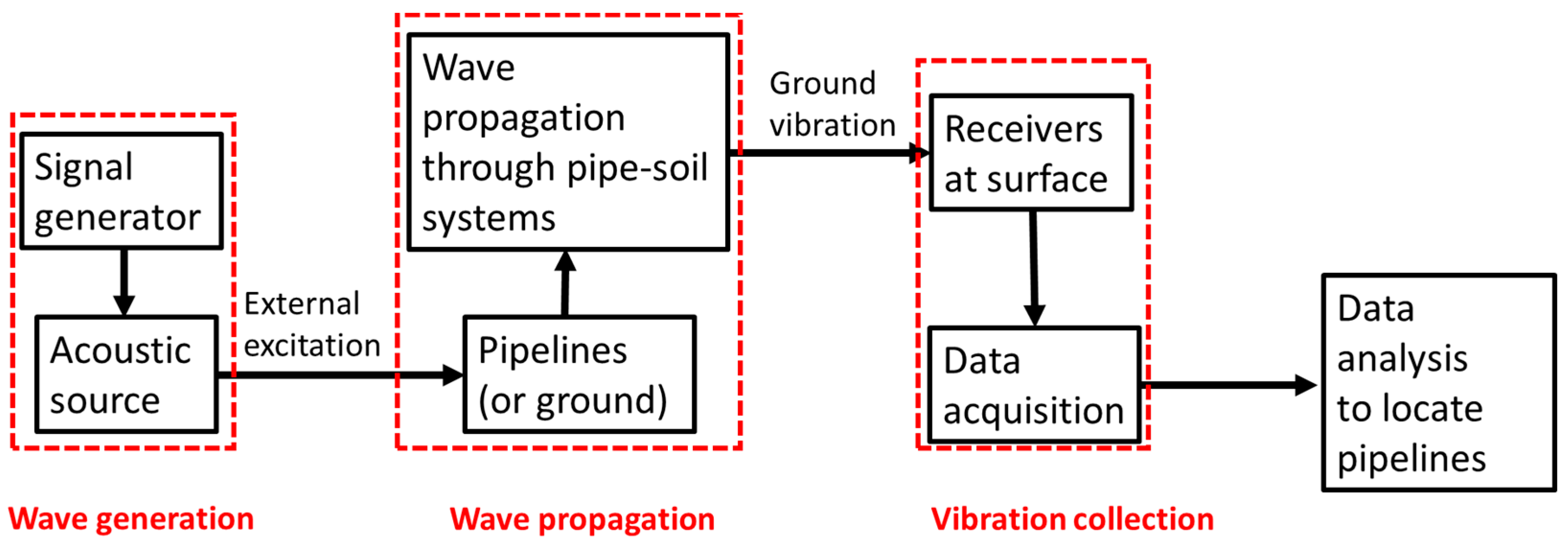
Figure 4.
Overview of acoustic locating methods.

Figure 5.
Traditional acoustic transmission method: (a) principle of the method, modified from [9]; (b) response versus location for conduit (directly excited) [11].
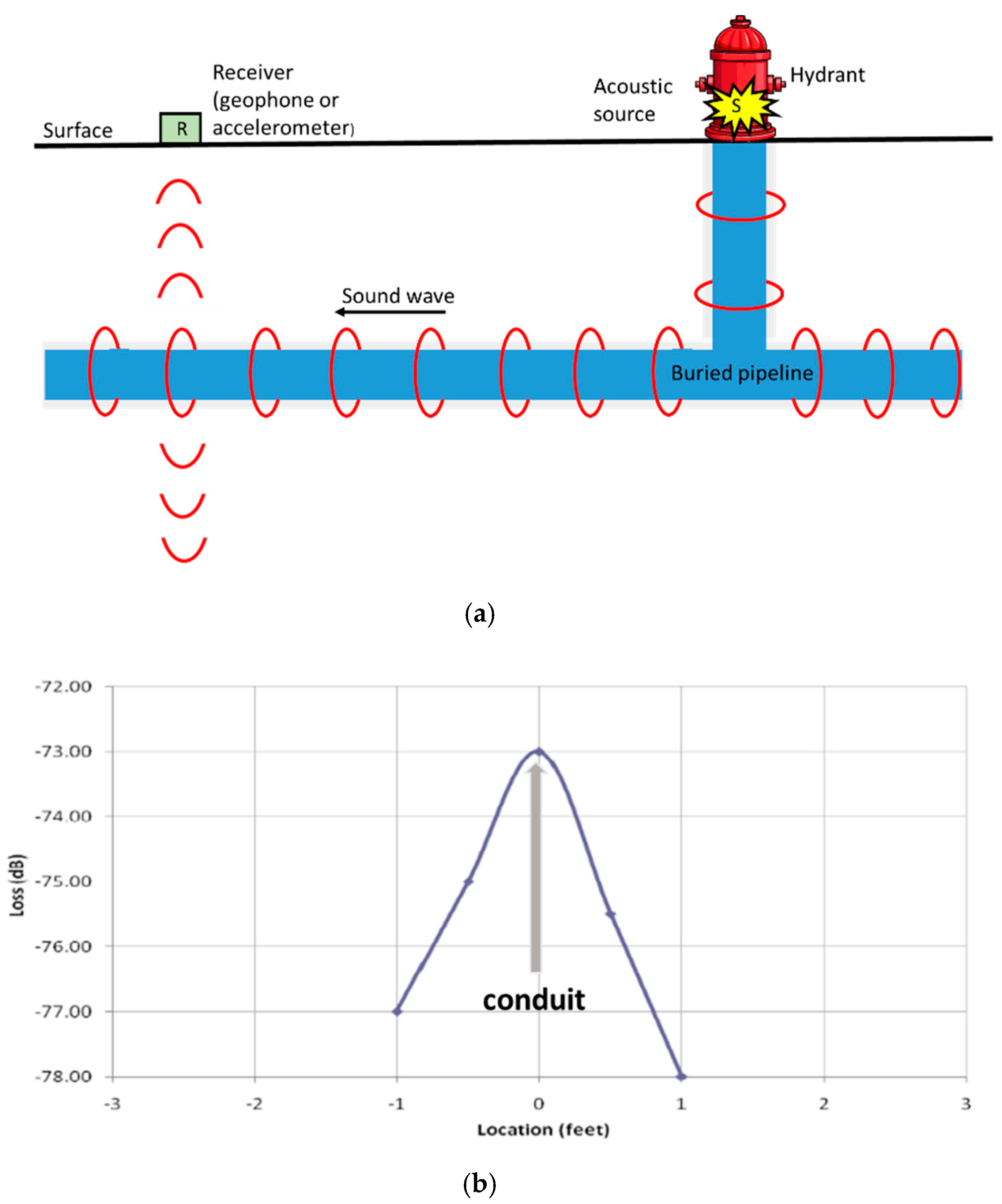
Figure 6.
Experimental set-up of pipe excitation method: (a) pipe rig layout; (b) shaker mounted on plastic end-plate; (c) grid of measurement points. [69], Copyright Elsevier, 2011.
Figure 6.
Experimental set-up of pipe excitation method: (a) pipe rig layout; (b) shaker mounted on plastic end-plate; (c) grid of measurement points. [69], Copyright Elsevier, 2011.


Figure 7.
Contour plots of magnitude and phase of the frequency response at 62 Hz: (a) magnitude of velocity in dB relative to velocity measured by geophones adjacent to excitation point; (b) spatially unwrapped phase in radians. The axes correspond to the axes shown in Figure 6c, rotated by 90°; the pipe runs up the center-line in each plot [69], Copyright Elsevier, 2011.
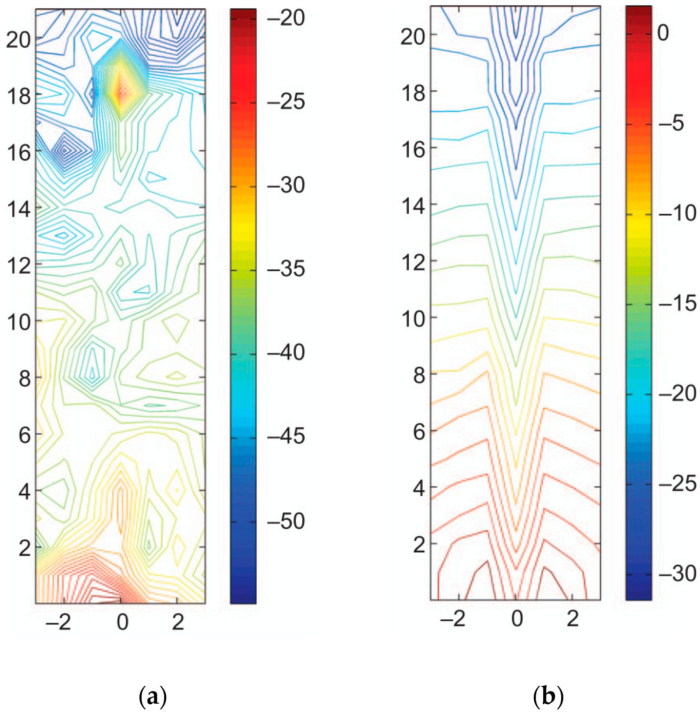
Figure 8.
The ground as a single-degree of freedom system [90].
Figure 8.
The ground as a single-degree of freedom system [90].
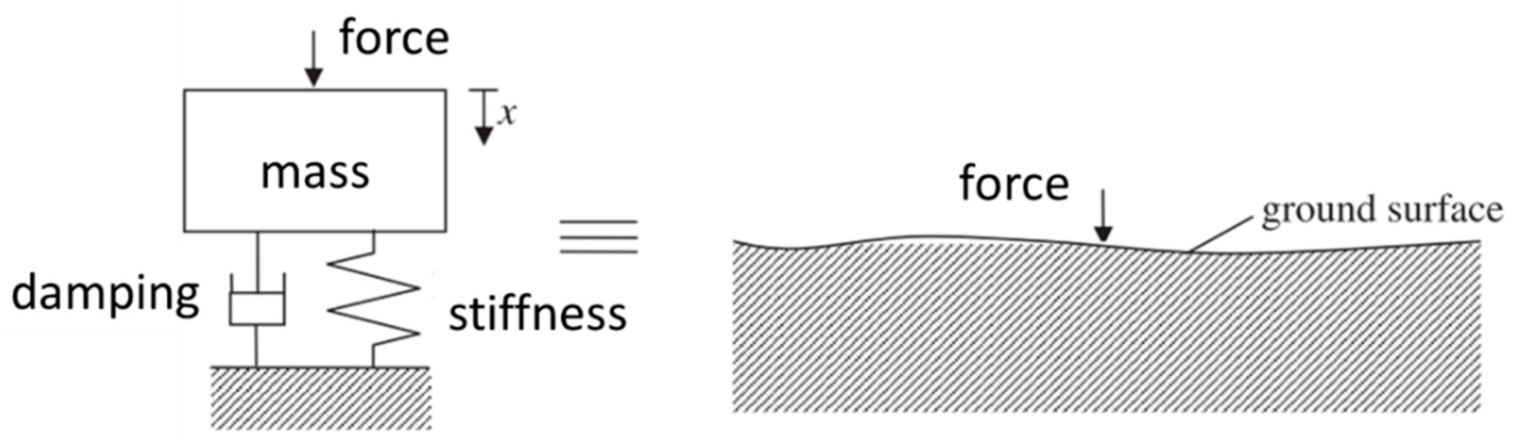
Figure 9.
Point vibration measurements: (a) pipe rig prior to burial; (b) acoustic source (shaker); (c) measurement lines (the cross are for illustrative purposes only) [90].
Figure 9.
Point vibration measurements: (a) pipe rig prior to burial; (b) acoustic source (shaker); (c) measurement lines (the cross are for illustrative purposes only) [90].
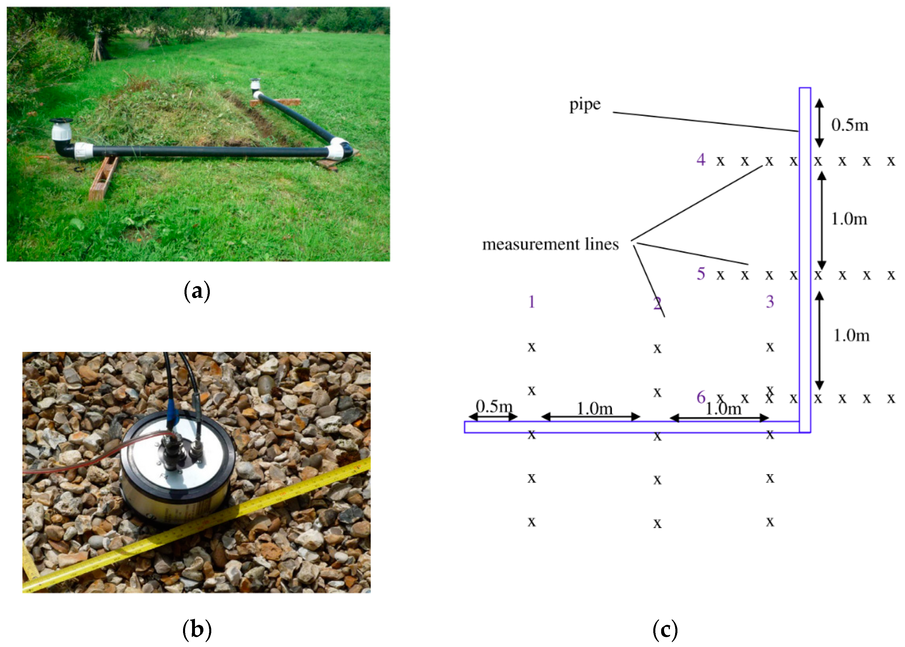
Figure 10.
Detection results of point vibration measurements: (a) resonance frequencies along measurements lines; (b) accelerance magnitude at the resonance along measurement lines [90].
Figure 10.
Detection results of point vibration measurements: (a) resonance frequencies along measurements lines; (b) accelerance magnitude at the resonance along measurement lines [90].
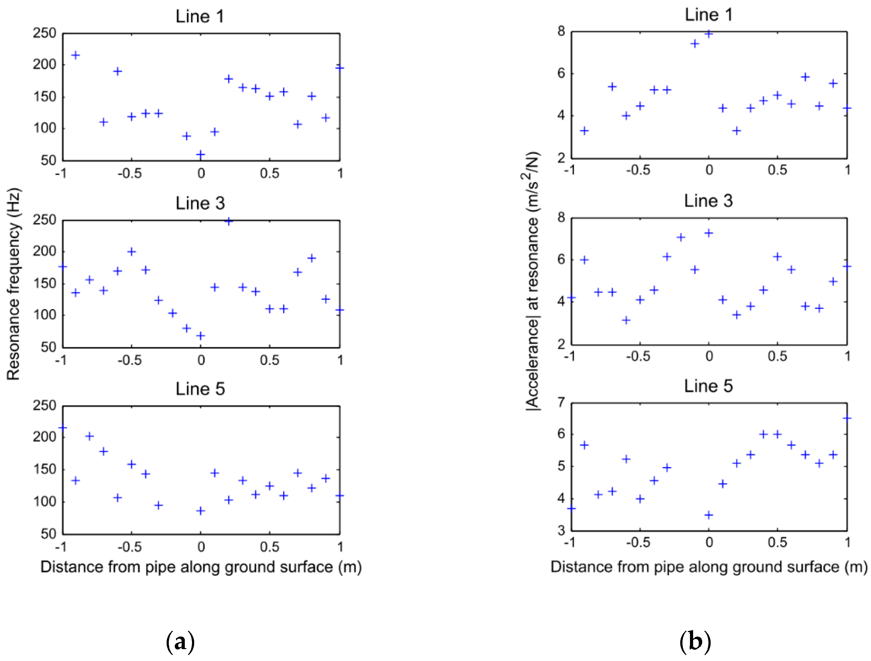
Figure 11.
Principle of seismic wave methods, modified from [99].
Figure 11.
Principle of seismic wave methods, modified from [99].
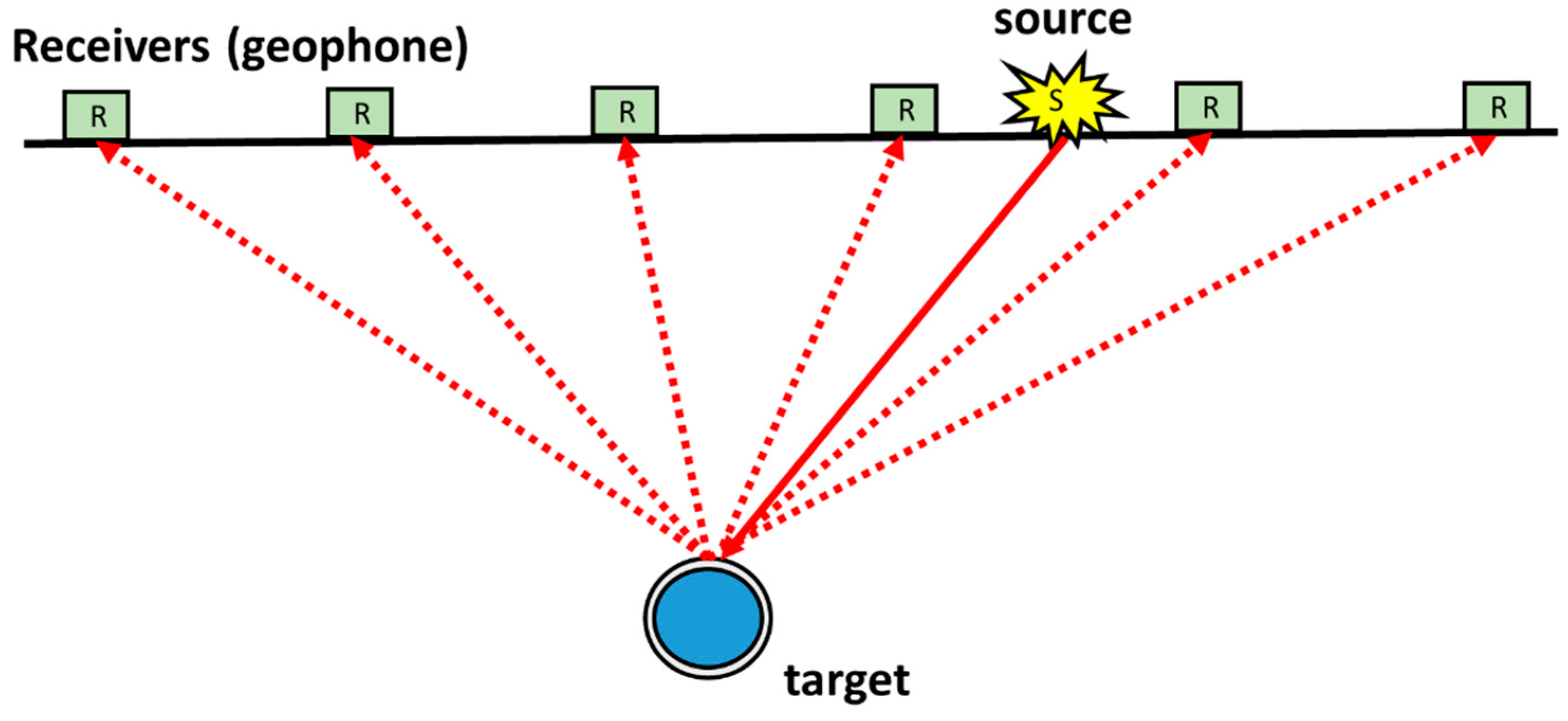
Figure 12.
(a) Experimental set-up for compressional wave method; (b) specially designed platform used to couple the shaker to ground [101], Copyright AIP Publishing, 2011.
Figure 12.
(a) Experimental set-up for compressional wave method; (b) specially designed platform used to couple the shaker to ground [101], Copyright AIP Publishing, 2011.

Figure 13.
Cross-sectional image produced from compressional wave method. The white bold line shows the location of the target [101], Copyright AIP Publishing, 2011.
Figure 13.
Cross-sectional image produced from compressional wave method. The white bold line shows the location of the target [101], Copyright AIP Publishing, 2011.

Figure 14.
(a) Experimental set-up for shear wave method [102] Copyright Elsevier, 2014; (b) specially designed platform used to couple the shaker to ground [100].
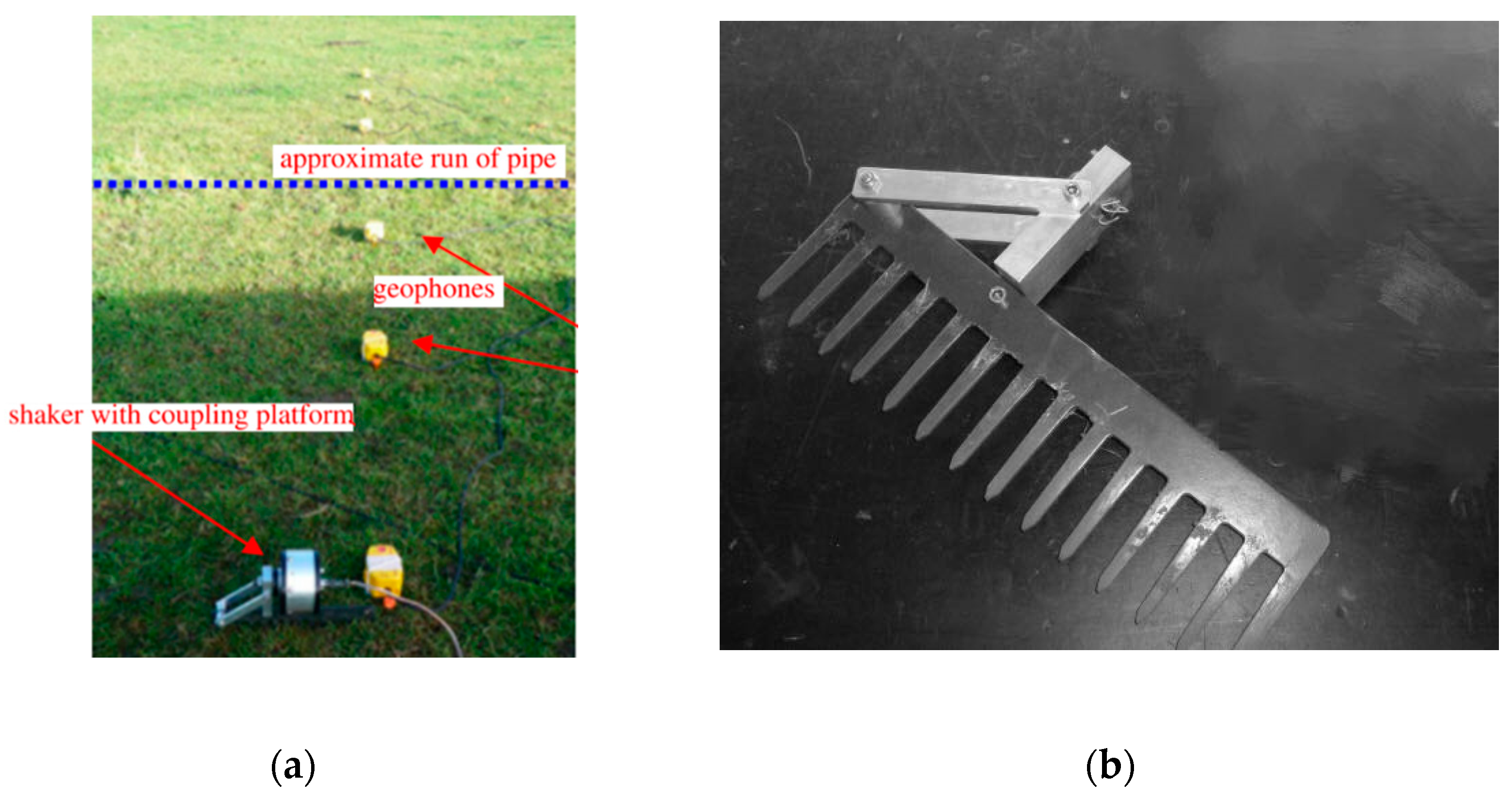
Figure 15.
Cross-sectional image produced from shear wave method using two different wave speeds. The black bold line shows the location of the target [102], Copyright Elsevier, 2014.
Figure 15.
Cross-sectional image produced from shear wave method using two different wave speeds. The black bold line shows the location of the target [102], Copyright Elsevier, 2014.

Figure 16.
Mine detection system using surface wave method [107], Copyright IEEE, 2001.
Figure 16.
Mine detection system using surface wave method [107], Copyright IEEE, 2001.
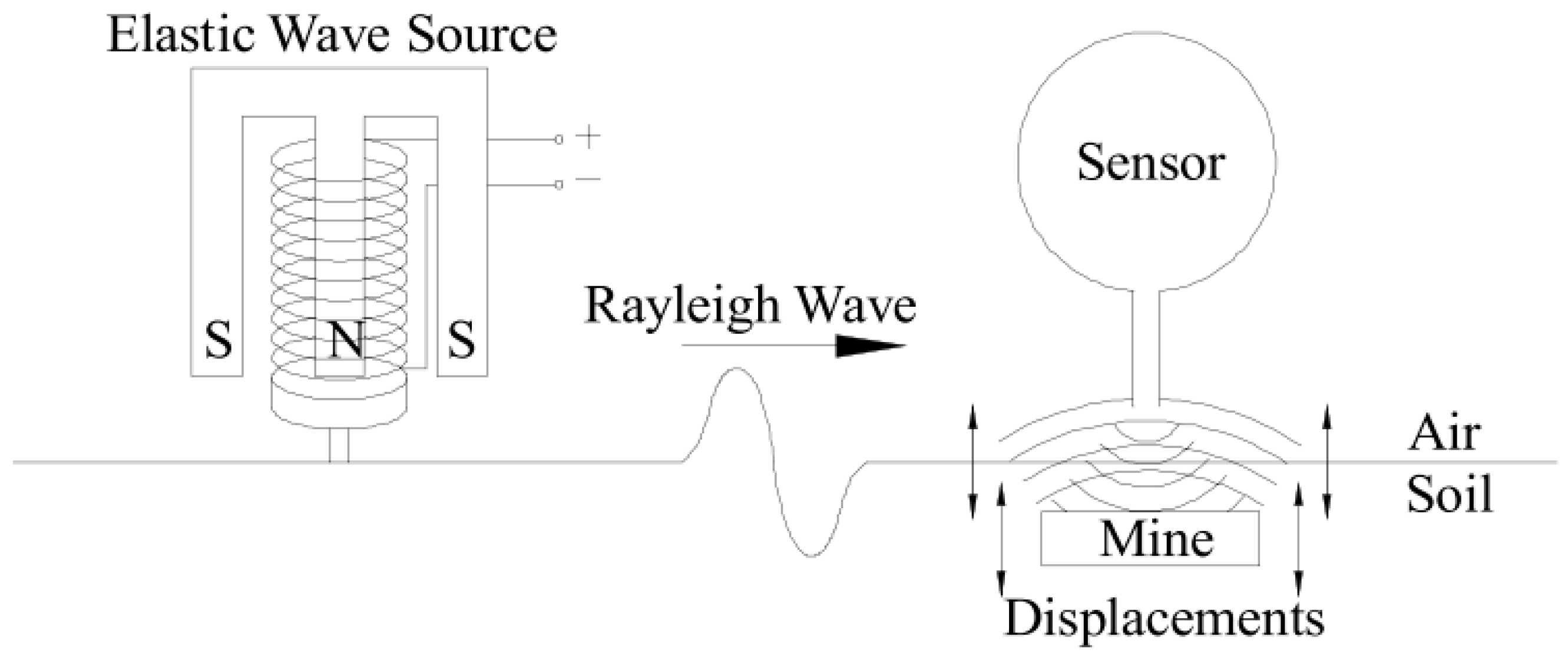
Figure 17.
Experimental set-ups of surface wave method in present of (a) a void; (b) a metal barrel [112].
Figure 17.
Experimental set-ups of surface wave method in present of (a) a void; (b) a metal barrel [112].

Figure 18.
Buried pipelines localization using the System Combiphon [116].
Figure 18.
Buried pipelines localization using the System Combiphon [116].
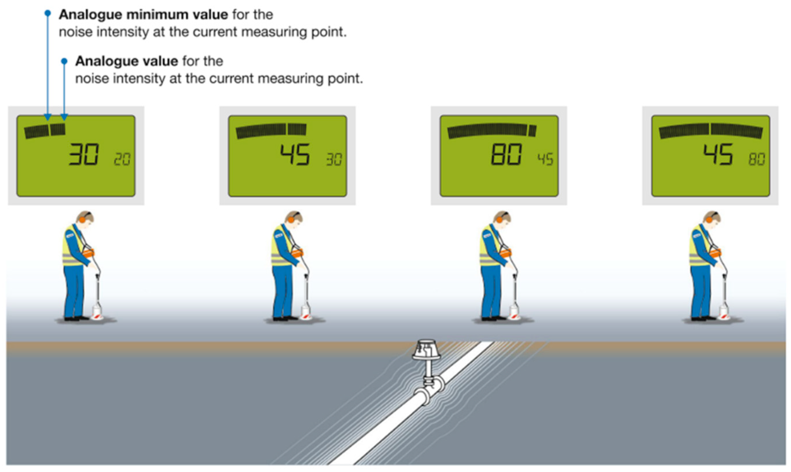
Figure 19.
The Ultra-Trac® APL (a) the basic principle; (b) the display window [118].
Figure 19.
The Ultra-Trac® APL (a) the basic principle; (b) the display window [118].
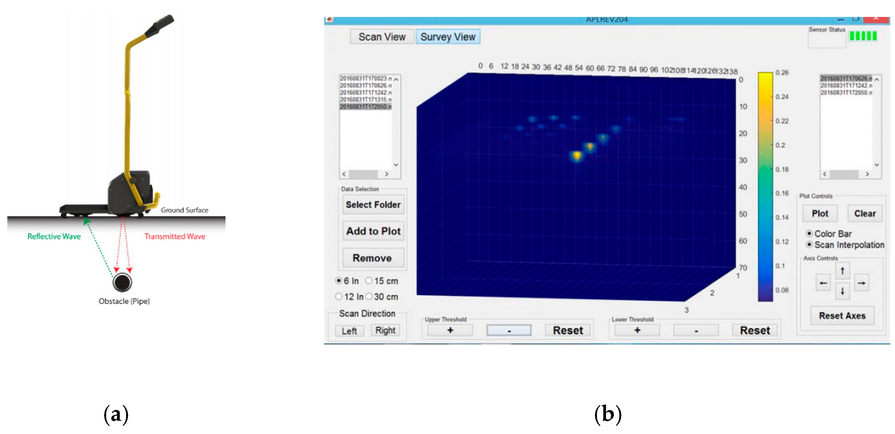
Figure 20.
Axisymmetric pipe discontinuities: (a) wall thickness change; (b) wall elasticity change; (c) internal radius change [131], Copyright Elsevier, 2005.
Figure 20.
Axisymmetric pipe discontinuities: (a) wall thickness change; (b) wall elasticity change; (c) internal radius change [131], Copyright Elsevier, 2005.
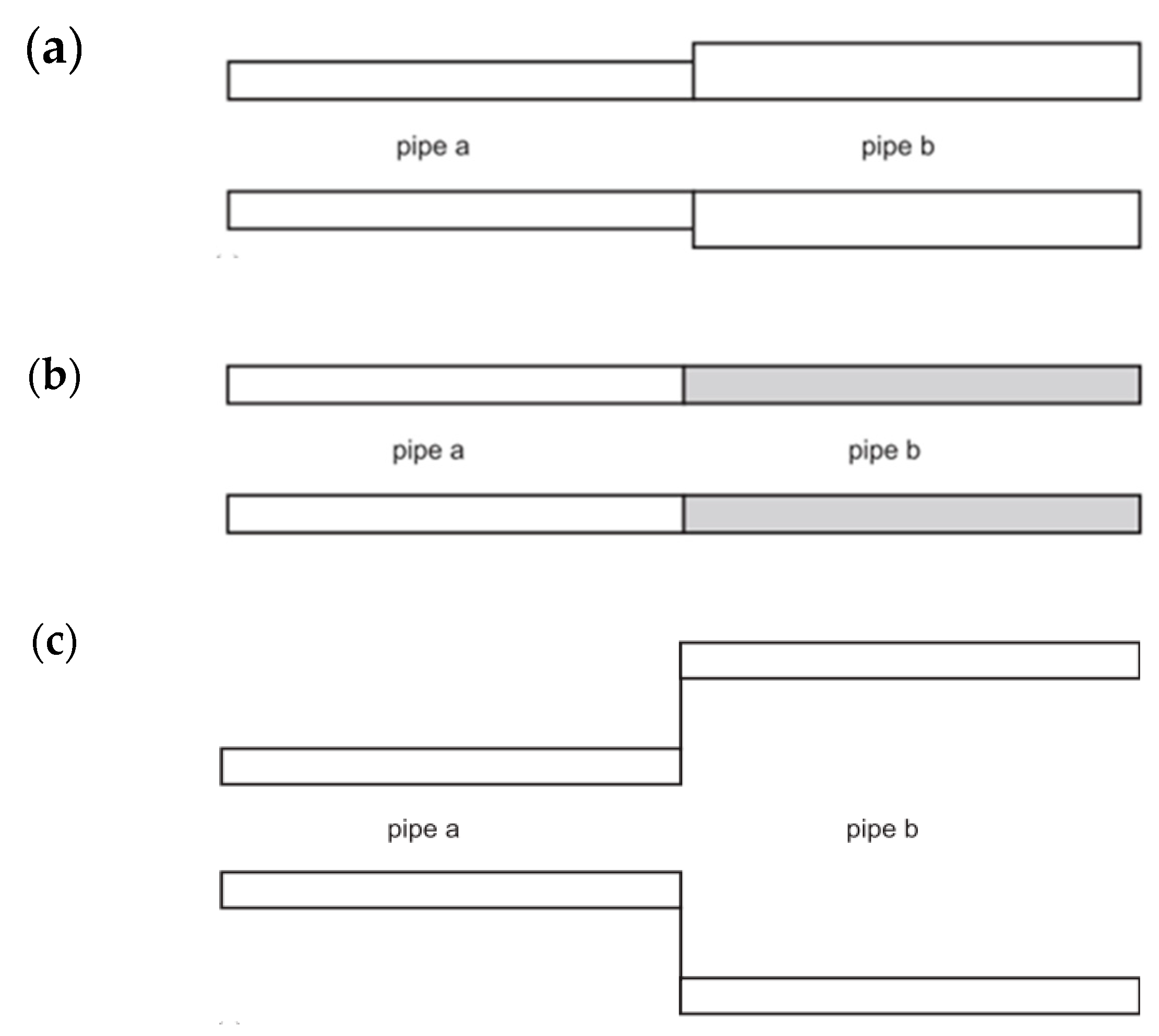
Figure 21.
Selection of pipe localization methods considering different conditions, modified from [11].
Figure 21.
Selection of pipe localization methods considering different conditions, modified from [11].
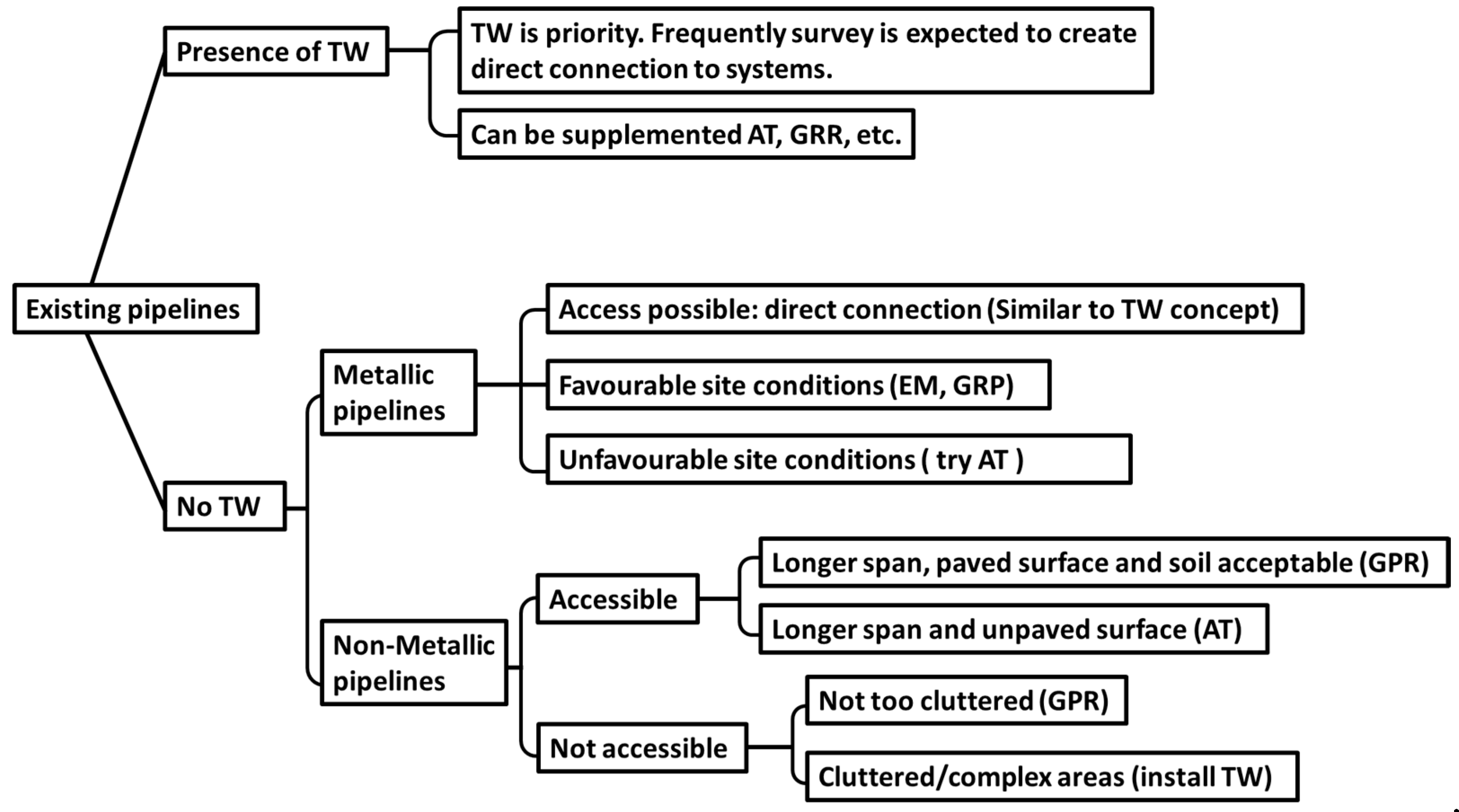

Table 1.
Summary of the theoretical study on wave propagation in pipe systems.
| Refs. | Model Description | Experimental Set-Up | Study Summary |
|---|---|---|---|
| [26] | Infinite hollow cylinders covering the transition from the case of a thin shell to the Pochhammer case of a solid cylinder | - | Plane-strain vibrations both axially symmetric and non-axially symmetric |
| [28,29] | A hollow circular cylinder of infinite extent | - | Three-dimensional investigation of the most general type of harmonic waves |
| [32] | Liquid-filled elastic tubes waveguides: PVC (Polyvinyl chloride) and aluminum | A thick-walled aluminum tube containing water with its lower end closed by a Lucite plate; A PVC water pipe dosed by a thin plastic insert at its bottom | Low-frequency propagation modes ET0 and ET1, dispersion behaviours and particle displacement profiles |
| [33,34] | Five cases including a cylindrical shell in vacuum (V/S/V), a cylindrical shell surrounded by a liquid (V/S/L), a hypothetical liquid column(L/V), a cylindrical shell filled with liquid (L/S/V), and a cylindrical shell immersed in an infinite liquid (L/S/L) | Steel cylindrical shells of 1 m suspended in either a water tank for the (L/S/L) measurements or in air for the (V/S/V) measurements; The shells filled with air or water and suspended in water or air for the cases (V/S/L) and (L/S/V). Water is the liquid and air is the equivalent of the vacuum | Dispersion curves, attenuation due to radiation, displacement distribution and stress distribution |
| [46,47,48,49] | Cylindrical elastic shells (steel, hard rubber[46]) filled with fluid; an infinite cylindrical elastic shell (steel) [49] | - | Wave propagation behaviours, energy distribution, vibration and radiation from monopole excitation |
| [63,64] | Fluid-filled pipes surrounded by an infinite elastic medium which can support both longitudinal and shear waves | A water-filled MDPE (Medium-density polyethylene) pipe of 2 m in air, secured vertically, with the lower end sealed; The MDPE pipe is terminated at each end in a large tank, being laid in the standard manner in a mostly sand backfill | Two axisymmetric wave types: fluid dominated wave and an axial shell wave |
| [65] | A submerged plastic water pipe | A water-filled MDPE pipe of 2 m, secured vertically, with the lower end sealed and suspended in water tank | The low-frequency acoustic propagation and attenuation characteristics |
| [66] | Buried fluid-filled pipes: inclusion of shear coupling at a lubricated pipe/soil interface | Same as [63,64] | The effects of shear coupling in lubricated contact condition |
| [58,68,70] | Fluid-filled pipes (PVC and cast iron) buried in sandy soil and clay soil, with no slippage between the soil and the pipe wall | Same as [63,64]; A 150 mm diameter PVC pipe of 200 m, buried in soft clay soil at a depth of 2.4 m [80] | Fluid-dominated wave; shell-dominated wave, structure and fluid motions; ground displacements due to fluid-dominated wave |
| [71] | A buried gas-filled steel pipe | The steel pipe with diameter of 5.08 cm m and a wall thickness of 4.76 mm, buried 0.762 m beneath the surface | Surface displacements due to gas-dominated wave |
| [75,76,77,78] | Buried iron water pipes | A 21.8 m long section of 4-inch bore pipe; A 19.8 m long section of 6 inch bore pipe; A 18.8 m long section of 10 inch bore buried street mains; A longer 49.1 m section of 6 inch bore pipe [75]; Buried 6 inch bore ductile iron water mains [76,77,78]. | The dispersion behaviour, displacement contribution, the effects of soil properties and attenuation characteristics |
Table 2.
Main features of different acoustic pipe locators according to their brochures.
| Representative Locators | Source and Receiver | Limitations | Optimal Detection Range | Advantages |
|---|---|---|---|---|
| FUJI NPL-100 [122] | Piezoelectric acceleration sensor; vibrator oscillator |
| ||
| RADIO DETECTION RD500 [123,124] | 3 transmitters to suit different application points; 2 devices for probing the soft and hard surface, respectively | Locating reduced for the pipe under pavement or concrete; Locate range reduced at the point where the pipe goes into a tee or joins a larger pipe |
|
|
| SEWERI System Combiphon [116,125] | Generator G5 central control unit and various impulse generators; 2 oscillators (Knocker, Stopper) |
| ||
| Ultra-Trac® APL [118,126] | Cannot detect objects less than 12” deep |
|
|
Table 3.
Summary of different acoustic methods.
| Acoustic Methods | Access to Pipe | Data Collection | Imaging Type | Information of Pipe Location | Strengths | Limitations | |
|---|---|---|---|---|---|---|---|
| Traditional acoustic transmission method | Required | Single-sensor | Cross-sectional image | Run of the pipe |
|
| |
| Pipe excitation method | Required | Multi-sensors | Top view | Run of the pipe |
|
| |
| Point vibration measurements | Not required | Single-sensor | Cross-sectional image | Run of the pipe |
|
| |
| Seismic wave methods | Compressional wave method | Not required | Multi-sensors | Cross-sectional image | Lateral location and burial depth |
|
|
| Shear wave method | |||||||
| Surface wave method | |||||||
Table 4.
Applications and limitations of different non-acoustic localization technologies.
| Methods | Applications and Limitations |
|---|---|
| Trace wires (TW) [150] |
|
| Groun penetrating radar (GPR) [5] |
|
| Electromagnetic methods (EM) [9] |
|
| Magnetic mehtods (MM) [151] |
|
| Infrared thermography (IF) [18] |
|
© 2020 by the authors. Licensee MDPI, Basel, Switzerland. This article is an open access article distributed under the terms and conditions of the Creative Commons Attribution (CC BY) license (http://creativecommons.org/licenses/by/4.0/).
Share and Cite
MDPI and ACS Style
Liu, Y.; Habibi, D.; Chai, D.; Wang, X.; Chen, H.; Gao, Y.; Li, S. A Comprehensive Review of Acoustic Methods for Locating Underground Pipelines. Appl. Sci. 2020, 10, 1031. https://doi.org/10.3390/app10031031
AMA Style
Liu Y, Habibi D, Chai D, Wang X, Chen H, Gao Y, Li S. A Comprehensive Review of Acoustic Methods for Locating Underground Pipelines. Applied Sciences. 2020; 10(3):1031. https://doi.org/10.3390/app10031031
Chicago/Turabian StyleLiu, Ying, Daryoush Habibi, Douglas Chai, Xiuming Wang, Hao Chen, Yan Gao, and Shuaiyong Li. 2020. "A Comprehensive Review of Acoustic Methods for Locating Underground Pipelines" Applied Sciences 10, no. 3: 1031. https://doi.org/10.3390/app10031031
Note that from the first issue of 2016, this journal uses article numbers instead of page numbers. See further details here.