Feasibility Analysis of a Double-Acting Composite Cylinder in High-Pressure Loading Conditions for Fluid Power Applications


University of Modena and Reggio-Emilia, Enzo Ferrari Engineering Department, Via Vivarelli 10, 41125 Modena, Italy
Appl. Sci. 2020, 10(3), 826; https://doi.org/10.3390/app10030826
Submission received: 27 December 2019
/
Revised: 18 January 2020
/
Accepted: 21 January 2020
/
Published: 23 January 2020
(This article belongs to the Section Mechanical Engineering)
Abstract
:A preliminary study on a double-acting hydraulic cylinder subject to high-pressure loading conditions (pressure = 350 bar) and with a bore diameter of 300 mm is presented. The substitution of the reference steel cylinder tube with a multi-material tube is investigated. In detail, a solution providing a steel thin inner liner wrapped by carbon composite materials is analytically and numerically tested in terms of weight reduction. The composite lay-up design and the component geometry are built to comply with manufacturing constraints for a relatively high-volume production. The alternative multi-material cylinder is designed to ensure the same expected performance as its steel counterpart. Firstly, the non-conventional hydraulic cylinder was designed by extending Lamé’s solution to composite materials, by adopting the micro-mechanics theory of composites in order to bear the maximum operating pressure by monitoring its radial and axial deformation. The selection of the most appropriate carbon reinforcement was investigated. The influence of the stiffness-to-weight and the strength-to-weight ratio of the reinforcement on the design is discussed. Secondly, finite element analyses were performed to evaluate the occurrence of buckling and the modal response of the actuator considering the fluid and of the cylinder own weight influence. The results confirm the validity of the new cylinder tube design compared to the reference steel component. The proposed barrel weights 80 kg compared to the 407 kg of the reference cylinder, with a weight reduction of ~80%. Furthermore, it has a compact design with a decrease of the barrel outer diameter of ~5.3%.
1. Introduction
Weight reduction and fuel consumption optimization are challenging tasks during the design of vehicles [1,2], both in the automotive and in the handling machinery area. These requirements have traditionally been met by adopting innovative materials such as composites [3,4] and investigating new engine architectures [5,6]. In fact, vehicles can be categorized as (i) light duty vehicles, e.g., cars, SUVs; (ii) industrial heavy vehicles, e.g., commercial vehicles and vans; and also (iii) earth moving machines, e.g., excavators and mobile platforms.
In the heavy vehicles contest, hydraulic actuators can be exploited to minimize both the overall vehicle weight and to rationalize the weight of a prescribed component by increasing, for example, the transportable loading of the vehicle itself [7,8,9,10] or by significantly reducing the mass of the ballast required for vehicle stabilization.
Hydraulic cylinders are usually manufactured using traditional metals. In fact, high strength steels are applied for the rod and the cylinder tube whereas the pistons are generally in aluminium. The main aspects of the hydraulic cylinder design are described by Hunt et al. [11], Speich et al. [12], and Vullo [13], whose manuals provide guidelines for successfully designing such components. These manuals present a comprehensive scenario of problems and targets that need to be considered when designing the actuator, e.g., buckling analysis, strain and stress analyses, sealing performance, and autofrettage investigation.
Buckling analysis and tribology problems between the ring seal piston and cylinder, and the damping vibration in the traditional hydraulic cylinder [14] have been extensively investigated.
In 2005, Gamez-Montero et al. [15] evaluated the buckling instability considering initial misalignment as an imperfection in the rod cylinder tube intersection. Their research defined the influence of the misalignment angle and friction coefficient on the buckling load by both numerical and experimental approaches. Baragetti et al. [16,17] presented numerical models to analyze the buckling behavior of a double-acting cylinder. Their analytical and experimental models studied the influence of the friction coefficient, the geometrical imperfections between piston and rod-cylinder connections and the weight of the oil. A mathematical formulation, which accounts for the parameters previously introduced, was given and compared to experimental data. The pressure distribution acting on the wear rings was assumed in [17] to be triangular. This profile was probably suggested due to the fact that one of the sides of the seal is subject to zero pressure. However, the results of Field and Nau [18] indicate that the pressure profile along the contact zone remains essentially constant rather than triangular. In the case of rectangular seals with rounded edges, the pressure distribution exhibits lateral bumps for a frictionless contact whose values may be computed with the analytical approach presented in [19]. Therefore, the initial hypothesis of the pressure distribution considered between the seal and the piston rod of a hydraulic actuator influences the wear of the seals and the leakage of the actuator. This aspect becomes relevant in an analytical formulation for misalignment condition, see [16,17]. The interest reader is addressed to the work in for an overview of the sealing problems that applies the theory of elastohydrodynamic lubrication an compares the numerical results with to experimental data.
Experimental results on buckling occurrence were presented by Morelli for a telescopic actuator [20], whereas Finite Element (FE) model was evaluated in [10] for a similar component made up of composites. Several works [21,22] consider stroke and cushioning devices to reduce the piston-rod kinetic energy during motion. The authors [21,22] also formed a mathematical model of hydraulic circuits to study the supply pressure influence, and they evaluated alternative solutions.
With regards to the material aspects, thin-walled composite cylinders have been studied for mechanical applications such as pressure vessels [23,24,25,26] and components that support energy absorption [27,28,29,30]. Composite materials have been exploited in pressure vessels in order to store chemicals [24,25]. These components were obtained by filament winding by coupling an inner liner with an outer composite laminate. They are designed to contain the fluid working at high pressure and occasionally, to carry partially the load. They also avoid the composite material corrosion. The technological constraints for the filament winding process on the fiber orientation are discussed in [31,32].
The possibility of using composite materials for hydraulic actuators seem to be meager; in fact, a few contributions are noticeable, see [7,8,9,10]. In [7], the authors present an experimental test of hydraulic actuators on static and fatigue cyclic pressurization and, also aspects regarding wear. In [8,10], a methodology is presented for designing the cylinder tube and the rod in composites of a hydraulic actuator, and the analytical results and the experimental data are compared. In [9], the feasibility of a hydraulic cylinder in composites is investigated by numerical FE analyses. Static analyses are exploited to investigate the stress and the strain field caused by oil pressure. In addition, the buckling occurrence of the rod is analyzed. Optimization techniques have been applied to cylinder composite stacking sequence and shape in order to increase the critical buckling load. In [10], a hydraulic actuator made up of composites has been applied to a telescopic hydraulic cylinder where the weight reduction is ~96% compared to the cylinder in steel, and it costs half of the steel counterpart.
For a double-acting cylinder, cylinders manufactured by composites have been investigated that do not exceed the bore diameter and the axial length of 200 mm and 1946 mm, working at maximum operating condition of 380 bar, see [7].
The present work defines a methodology to evaluate a weight efficient alternative design for an actuator with a bore diameter of 300 mm and an axial length of 2300 mm working at high pressure (350 bar). To the best of knowledge, no such methodology for an actuator of these dimensions has been presented before, in the technical literature.
The paper is organized as follows. Section 2 analyses the reference steel actuator. A Lamé’s solution [33] is obtained for orthotropic materials in Section 3, and the formulas developed for composite thick-walled cylinder stresses and strains are presented. In Section 4, three types of fiber were investigated and the composite lamina structural properties are illustrated. In Section 5, the thickness of the composite cylinder tube is calculated by evaluating the required circumferential and axial load-bearing requirements. The selection of the most appropriate carbon reinforcement is analyzed, and the influence of the stiffness-to-weight and the strength-to-weight ratio of the reinforcement on the design is discussed. In Section 6 advanced topics such as buckling and dynamic behavior are discussed comparing the original solution and the composite replacement. The optimal solution is a multi-material design component that adopts an inner and thin-walled steel liner and a composite barrel 13.3 mm thick. This solution is particularly promising in terms of wear resistance and reducing fatigue as a result of the inner metallic liner.
2. The Reference Hydraulic Actuator
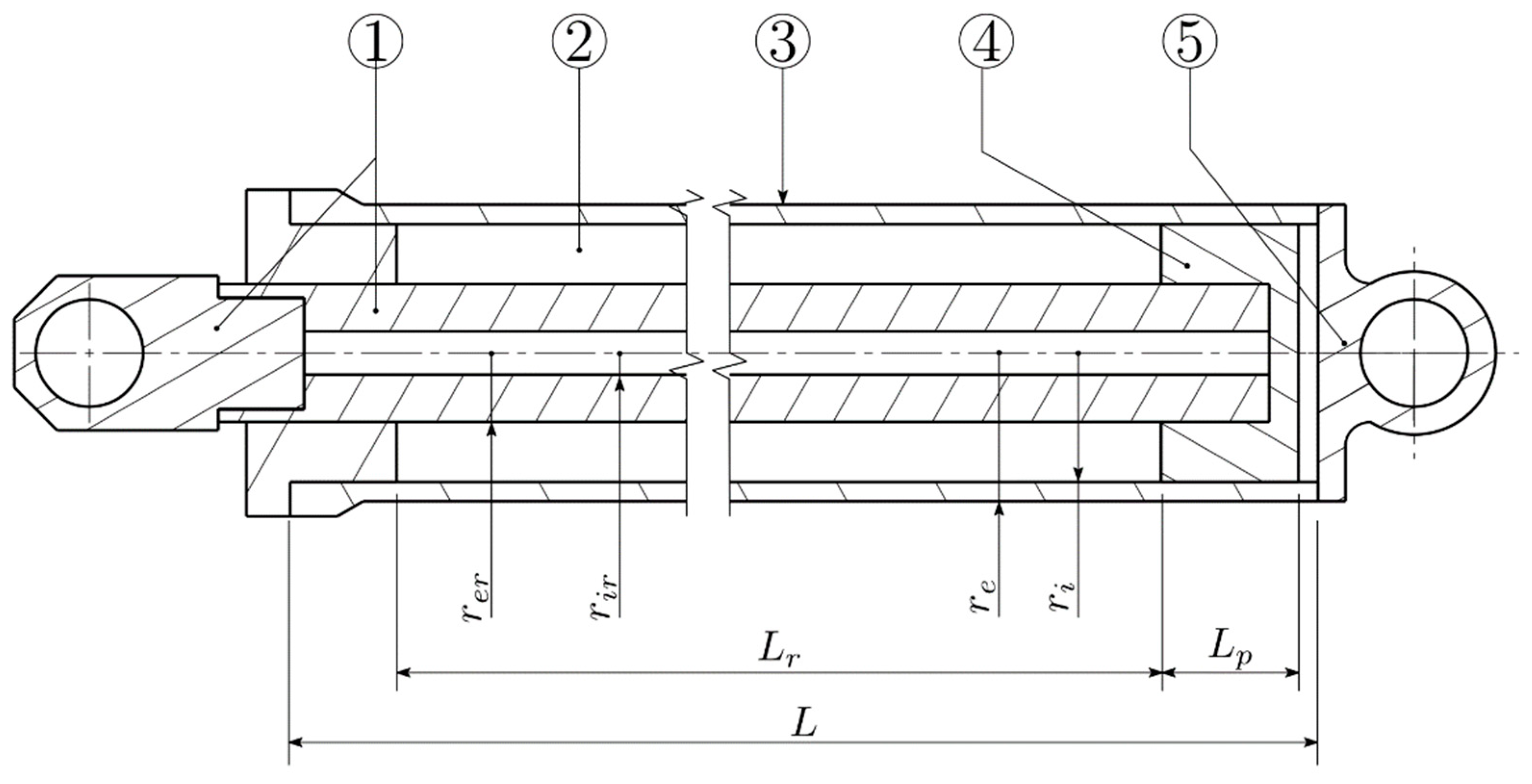
Figure 1 displays the geometry of the title problem, and it clarifies the meaning of the main components and the symbols adopted in the following. The material properties of the reference hydraulic actuator are shown in Table 1. The cylinder tube represents ~51% of the overall hydraulic actuator weight for the reference configuration, and the components of Table 2 are labeled as in Figure 1.
The reference hydraulic cylinder tube is 150 mm in bore radius (ri), 172.5 mm in external radius (re), and 2300 mm in length (L). The piston rod has a hollow circular cross-section where the inner radius (rir) and the outer radius (rer) are 25 mm and 80 mm, respectively. The piston rod stroke is 1960 mm (Lr); the axial length of the piston (Lp) is 160 mm. The flanges at the extremities of the actuator are in aluminium alloy 7075-T6. The nominal operating pressure is 35 MPa. In [8,9], the cylinder tube was in S275JR steel, and it was designed for at 30 MPa and 35 MPa working pressure, similarly our reference geometry. In [8,9], the cylinder bore radius was equal to 25 mm and equal to 70 mm, i.e., one sixth and about a half of our component, respectively. The S275JR steel has a lower yielding strength (σy = 235 MPa) compared to the S355 steel used in the present study.
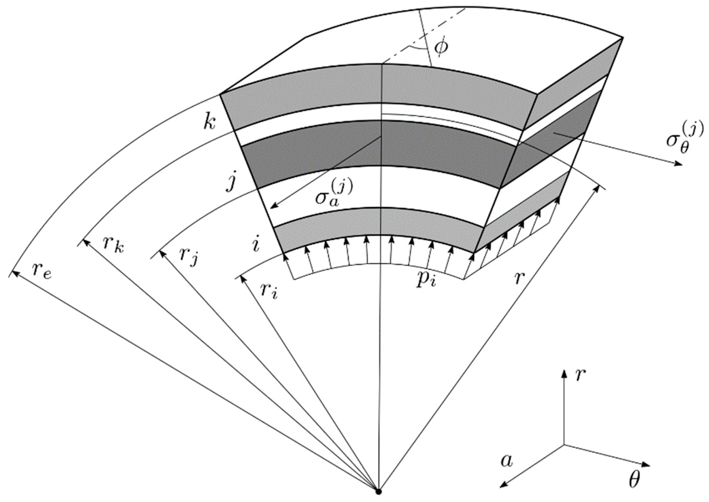
The cylindrical coordinate system (r, θ, a) is adopted for the analytical formulation, and it defines the radial, hoop, and axial directions, respectively, for a generic axisymmetric geometry, see Figure 2. The cylindrical section of the component is internally pressurized, and it is represented by multiple j-th layers whose radial thickness is equal to tϕ. Since the reference actuator is in steel, it is considered as a homogeneous and isotropic material and its cross-section consists of one layer 22.5 mm thick. For composite material, the mechanical properties (e.g., strength and stiffness) are influenced on the reinforcement orientation angle ϕ; therefore, this information is mandatory for the definition of the optimal cylinder design in composite.
The internal yield pressure (pi) of the reference steel cylinder tube was calculated using Lamé’s solution for thick-walled vessels. The circumferential stress (σθ|r = ri) and the radial displacement (ur|r = ri) at the inner cylinder radius were then evaluated accordingly. Results are shown in Table 3.
The first-yield condition represents a soft failure mode that precedes the catastrophic failure of the component, which is associated with the fully yielded state at burst pressure. The first-yielded state rather than the full yield was chosen for the following comparative safety analyses since the structural steel yielding phase has only a weak counterpart for composite materials. In addition, limiting the analyses below the first-yield threshold allows considerations based on linearity.
3. The Analytical Solution for Orthotropic Materials Adopting Lamé’s Approach
Material composite stiffness properties depend on the reinforcement orientation and reinforcement volume fraction [31]. For a unidirectional (UD) composite ply, a scale factor λ between the Young’s modulus in the principal reinforcement direction E1 and in the transversal one E2 can be defined as
The solution of the equilibrium and compatibility equations for the thick-walled composite vessel under plane stress assumptions returns the radial displacement u(r) as the following function of the radial position r,
where the C1 and C2 constants may be calculated with the aid of the boundary values of the cylinder radial stress (σr) at the inner radius (ri) and at the outer radius (re) of the cylinder, see Equation (3).
Thus, obtaining
where ν12 is the major Poisson’s ratio of the composite lamina.
The circumferential stress (5) and the radial displacement (6), as sampled at the inner cylinder tube diameter where both the quantities peak, may be expressed as follows,
Formula (6) also recalls the relation between the circumferential strain (ε θ) component at the inner radius and the local radial displacement.
In the problem under scrutiny, the inner radius and the operating pressure are imposed as design constraints, whereas the material and the outer radius are free variables and they are selected in order to ensure admissible values for (a) the peak stresses and (b) the radial compliance at the inner radius.
In the context of a technical feasibility study, a limited set of materials was selected, see Section 4 below. For each candidate material, a suitable outer radius (re) may be defined based on Equations (5) and (6) as
where the inner radial displacement and circumferential stress component are set at their maximum allowable values.
4. Material Selection
In [8,10], a carbon reinforcement with a standard elastic modulus (Ef = 230,000 MPa) has been adopted during the design of the cylinder tube; whereas in [9], a reinforcement characterized by an intermediate elastic modulus (Ef = 300,000 MPa) was investigated.
In the present work, unidirectional ply is considered; where the reinforcement is continuous and embedded in a thermoset epoxy matrix. Three types of fibre were investigated; the elastic and strength properties for these selected fibres are shown in Table 4. The elastic modulus of the reinforcement (Ef) ranges from 300,000 MPa to 620,000 MPa.
The unidirectional fiber reinforcement lamina is considered to be orthotropic. The in-plane elastic properties (E1, E2, G12, and ν12) of the lamina are evaluated by using the micro-mechanic predictions [26] referring to the principal axes of orthotropy, see Table 5.
The further out-of-plane elastic constants (E3, G23, G31, ν23, and ν31) for the lamina have been evaluated by imposing the transverse isotropy assumption [26] and the Poisson’s ratio conditions are detailed in [34]. The composites cylinder is design and manufactured by wrapping k unidirectional plies. The j-th layer with a peculiar orientation angle ϕ has a thickness equal to tϕ.
5. Cylinder Tube Stacking Sequence Definition
The two dominant structural requirements for the cylinder consist of (i) the retention of the pressurized fluid and (ii) the bearing of the axial load related to the double-acting nature of the actuator.
The design of a suitable composite material stacking sequence for the cylinder wall is discussed in the Section 5.1 with regards to the circumferentially active layers—i.e., the unidirectional plies whose fibres are orthogonally oriented with respect to the cylinder axis (90° plies, ϕ = 90° see in Figure 2); the sizing of the layers devoted to the support of the axial actions (0° plies, ϕ = 0° and the UD reinforcements are aligned with the cylinder axis, see in Figure 2) will be discussed in Section 5.2 below. The highly specialized nature of the unidirectional Carbon Fibre Reinforced Polymer (CFRP) material justifies in fact the disjoint sizing of axially and circumferentially oriented layers.
5.1. Design for Pressurized Fluid Radial Retention
The dimensioning of the circumferentially oriented portion (called 90° plies) of the stacking sequence is driven by the fulfillment of three constraints.
The main design constraint for the sizing of the circumferential plies cumulative thickness (t90°) is the thresholding of the circumferential stress value at inner tube radius; such constraint is reported as the first in the summarizing Table 6 below.
CFRP pressure vessel and gas bottle walls are mainly dimensioned according to such constraint; steel cylinder actuators are also designed within the respect of an equivalent stress value, where the circumferential component prevails.
However, a CFRP axial actuator tube designed according to this first constraint alone would suffer from an excessive radial expansion at the inner surface resulting in both seal leakage [35] and piston misalignment due to increased gap at the bearing bands.
The lower stiffness to critical stress ratio of the CFRP material substantially worsens this shortcoming in the title design with respect to a construction steel counterpart, and it raises the thresholding of the inner radial expansion to a major design constraint, which is also reported in Table 6.
In further contrast with the usual steel construction, the inner surface of the composite tube is tribologically unsuitable to pair seals and bearing bands in sliding contact [35,36], even when the inner layers are laid in direct contact with the mold.
A bonded inner steel liner is therefore employed to endow the sliding seals with a tribologically suitable counterpart. The insertion of a thin steel liner was considered also [8] and sketched in Figure 1 of [24]. In Figure 2, the liner might be represented as the i-layer located at the inner radius, over which the composite laminae will be stacked.
The thickness of the steel liner has been considered equal its minimum technologically allowable value of 2 mm; lower values would create manufacturing difficulties in respecting tolerances and surface quality, whereas higher values would unnecessarily increase the component weight.
The thickness of the steel liner is assumed infinitesimal in the pertinent structural calculations, and it inherits the circumferential and axial strain values from the composite layer it is bonded to, i.e., the CFRP tube inner surface; those strains that are cyclic in nature due to the succession of loading cycles may damage the steel liner and they have to be bounded within allowable values. A third design constraint in terms of admissible strains at the tube inner surface is hence to be considered, see Table 6. The admissible strain value for the steel liner is quantified in the following.
Being the liner a non-load-bearing element, its yielding can be tolerated as long as strain induced fractures do not appear. Such condition imposes not only that the instantaneous equivalent strain remains below the material elongation at break, but also the avoidance of cyclical hysteretic plastic loops and of the consequent low-cycle fatigue fractures. This latter condition is more stringent.
Figure 3a represents the hysteretic loop for an elastic perfectly plastic liner steel material, subject to cyclic circumferential strains ranging from 0 to εpeak; as usual, σy is the material yield stress and the E steel Young modulus rules the slope of the elastic loading/unloading lines. The hatched area represents the density of plastic strain energy locally dissipated each settled loop.
As pointed out in the elastic-perfectly plastic stress strain curve in Figure 3b, a limit peak strain value (εlim) exists such that, besides a first loading cycle in which yielding occurs, further cycles do not accumulate additional plastic strains. Such εlim strain value is associated to the limit condition of a null-area (i.e., null plastic strain energy density) hysteretic loop, and can be evaluated as follows.
Longitudinal fractures induced by the low-cycle fatigue are assumed not to occur in the steel liner if its strain levels are bounded below the εlim value under operating conditions, i.e., if inner radial displacement of the CFRP tube remains below εlim ri, see Equation (6).
Table 6 summarizes the three design constraints described above.
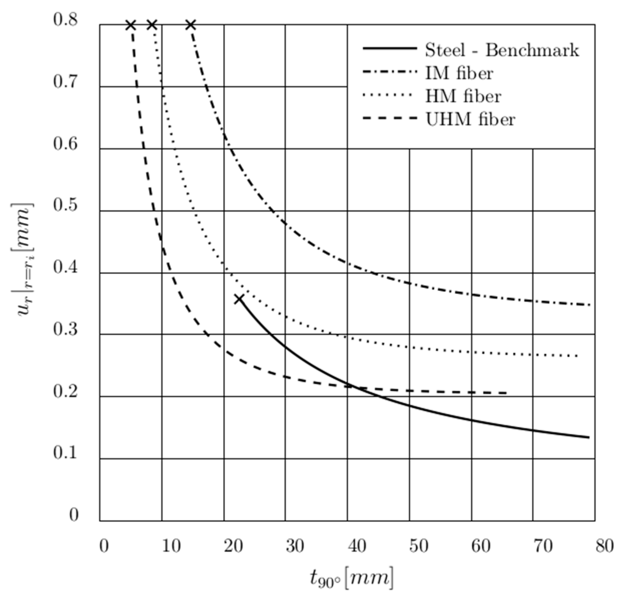
Figure 4 compares the different UD CFRPs on the radial displacement at the inner cylinder tube. Only the ultrahigh modulus (UHM) carbon fiber reaches the radial stiffness of the reference steel cylinder tube, with a feasible wall thickness of 13 mm. The condition that bounds the minimal thickness of the composite tube (at the point marked by a cross, in Figure 4) is the liner circumferential strain permitted, whereas the thickness of the steel tube is limited by its yielding (σy).
Considering the present component, in the case of UHM fiber the minimum 90° ply thickness required for bearing the inner pressure is 5.3 mm, whereas the original steel wall thickness is 22.5 mm. The thickness of the steel liner was considered equal to 2 mm in accordance with the minimum technological manufacturing process allowable to ensure both the geometrical and the surface finishing tolerances required.
5.2. Design for Axial Load Retention
For the present hydraulic component, the axial load (Pa) is due to pressure pi acting on the head while pulling, or on the pushing piston when retained at full stroke in the absence of position-limiting valves. Such loads can be, respectively, evaluated by referring to the cross where the pressure acts, as follows,
or as
where rer is the rod outer radius.
The 0° axially oriented ply amount is defined by the minimum cross section area A0° required in order not to overcome the longitudinal tensile strength of the material. For instance, this value σ1 corresponds to the strength of the unidirectional ply parallel to the reinforcement on the principal orthotropic system.
Unlike the circumferential case, the steel liner could be isolated from the composite tube axial deformation through an antifriction coating; however, this solution was not adopted in the present test case. The composite cylinder tube axial strain (εlim) has to be limited as well to preserve the inner bonded steel liner. Therefore, the required amount of axially oriented unidirectional plies can be calculated as follows.
Since circumferential retaining plies become less effective if stacked on an increasing thickness of material, it is advisable to wrap the axial plies over the outer circumferential layers. Unfortunately, due to manufacturing and technological constraints, circumferential and axial UD plies need to be alternated, or an unbalanced fabric has to be used. The required axial ply thickness was evaluated as 2.0 mm using the UHM fiber.
Therefore, by adopting the present methodology, the composite cylinder tube in UMH fiber that satisfies both the radial stress due to pressurization and the axial load detention due to the piston pushing and pulling requires a minimum overall thickness of 7.3 mm, reported in Table 7 as Case A. The optimal solution that introduces the inner steel liner is 13.3 mm thick named as Case B. It is composed of the steel liner (t liner = 2.0 mm) and 7.3 mm of UHM UD plies obtained as the sum of the plies required with the reinforcement aligned to the cylinder axis (t 0° = 2.00 mm, ϕ = 0° see Figure 2) and to the hoop direction (t90° = 5.3 mm). Case B is the most promising and compact solution in lieu of 22.5 mm of steel shell as in the reference assembly.
The composite solution that either omits or considers the liner is referred to as Case A and Case B, respectively.
6. Buckling Loading Conditions, Dynamic Modal Targets and Radial Deformation of the Cylinder at the Piston Locus
The radial deformation of the cylinder with the piston movement, buckling phenomenon, and dynamic natural response represent three main design targets for a hydraulic cylinder. In this section, these structural requirements are discussed in the light of the application of CFRP orthotropic materials by FE analysis using the commercial, closed source solver MSC.Marc2017.1. The modeling details are given below.
6.1. The Radial Deformation Analysis
The composite cylinder tube allows a greater radial expansion than its steel counterpart, especially when the wall thickness is kept minimal and UHM fiber is not used; this compliance reduces the effectiveness of the piston-bearing bands and sealing. However, the event of the pressure asymmetry needs to be considered since only one chamber is pressurized at a time.
Simplified linear FE analyses show an S-shaped wall deformation centered at the sealing point, with small overshoots due to the plate bending stiffness.
The reference steel geometry and the multi-material cylinder named Case B as shown in Table 6 were investigated. The modeling of the composite cylinder was obtained by superposition on the structural requirements previously discussed. This solution consists of (a) a metallic liner (tliner = 2 mm) and (b) UHM composites plies (t90° = 5.3 mm and t0° = 2.0 mm). The cylinder tube stacking sequence was modeled by homogeneously distributed regions along its thickness; the circumferential plies are alternated by the axial plies, and the stacking sequence is as follows [liner, 0,90,0,90,0,90,0,90,0] moving from the inner cylinder radius to the outer radius.
The elements adopted to discretize the barrel are four-noded, quadrilateral, isoparametric elements for axisymmetric applications (element type = 10, see [37]) with 15 elements along the wall thickness with an average size equal to 1 mm. The material properties of the reference cylinder and of the composite counterpart are reported in Table 1 and Table 4.
Both the reference and the multi-material cylinder were loaded at the inner radius for a half of their axial extent by the burst pressure pi equal to 67 MPa.
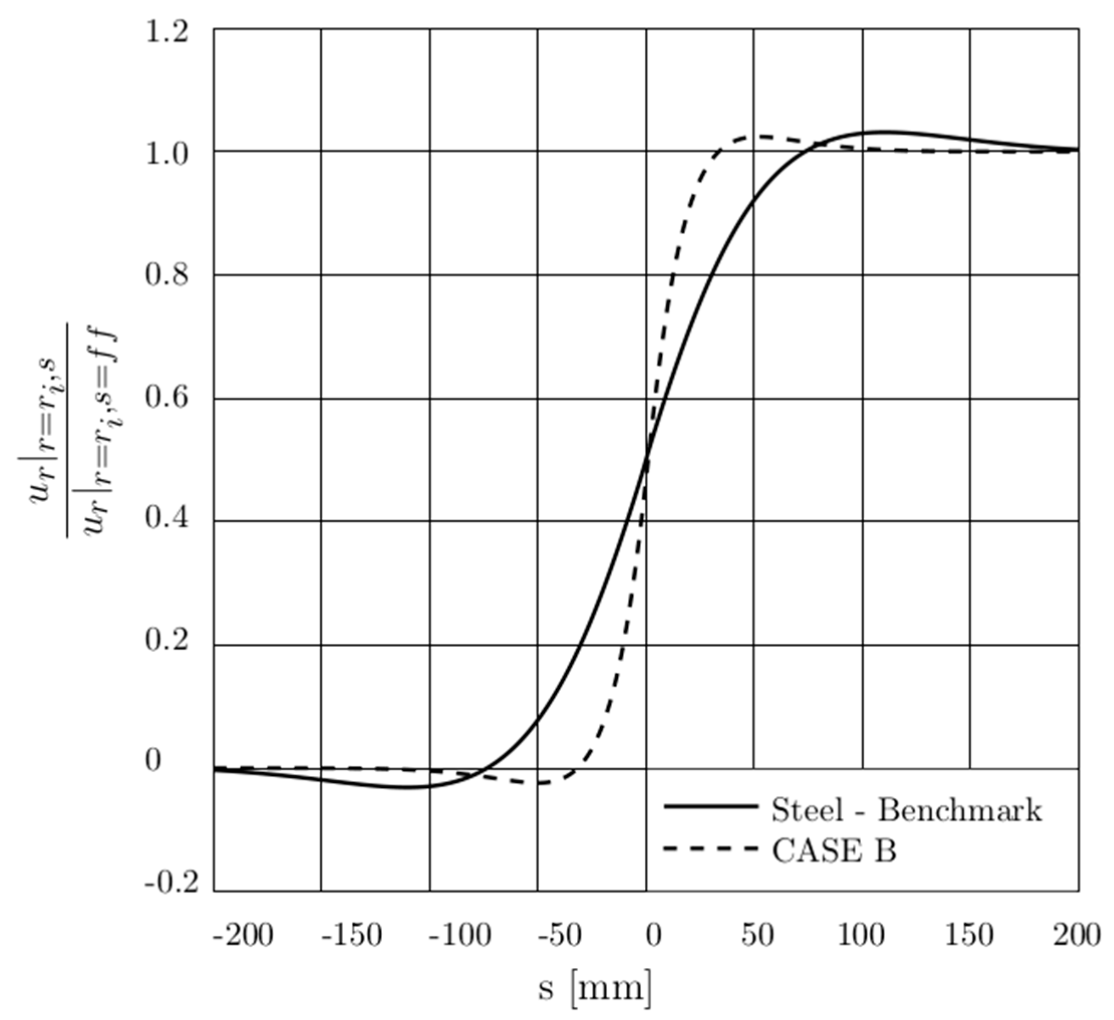
Figure 5 shows the radial deformation of the cylinder collected at the inner radius of the cylinder (ur|r = ri, s), normalized with respect to the radial deformation evaluated far from the loaded-unloaded transition cross-section at the inner radius of the cylinder (ur|r = ri, s = ff) along the cylinder axial extent (s). The parameter s is null at the mid-span axial length of the cylinder; the pressurized chamber appears on the right-hand side of Figure 5.
The normalized radial deformation decreases asymptotically to zero moving within the unloaded portion and increases to the value returned by the Lamé’s solution moving within the loaded portion. It is clear that the sealing acts on a cylinder section where radial deformation is half its asymptotic value. The maximum value of the normalized radial deformation of both the reference and the multi-material cylinder are comparable.
The radial inflation also decreases more rapidly in the composite Case B; the piston-bearing band on the unloaded side pairs an almost undeformed cylinder section.
6.2. The Bucking Analysis
Analytical and experimental investigations have been developed to study the critical buckling load of hydraulic cylinders. In the present paper, the hydraulic cylinder was modeled in analogy with the approach proposed in ISO standards [38] and based on Hoblit’s method [39].
However, a FE model was used rather than the analytical formula in order to consider the relevant shear deflection of the composite tube, due to the orthotropic behavior of this class of materials. Although the ISO norm assumes that the axial load is transmitted through the tube during the pushing phase, whilst in the actual working operation, such load is supported by the constrained fluid, and the composite barrel is relieved from the compressive load, retarding buckling incipience.
Comparative analyses were conducted following the ISO approach, which can be pragmatically described as a fixed-end pipe of length, connecting two rigid and rigidly supported tanks ([40], p. 37).
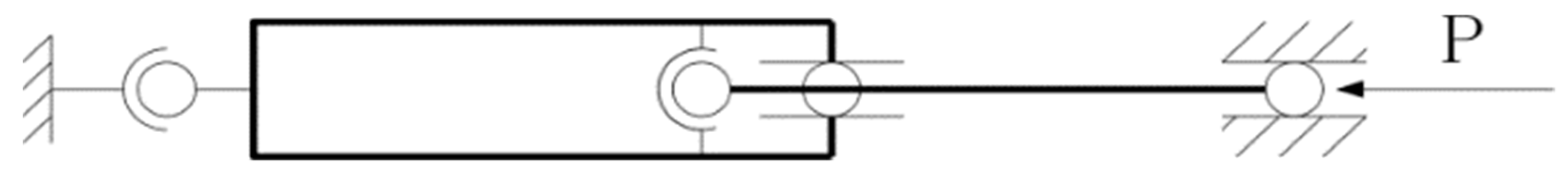
The mounting case method was modeled by FE as a pin-mounted hydraulic cylinder, where the cylinder cross sections at the piston location and at the further head cap extremity are assumed to be rigid, and the relative boundary conditions are presented in Figure 6.
It is worth to be noted that the actuator rod is laterally supported by the cylinder at the head cap bearing and at the piston mid-point. The axial load is transmitted from the rod end to the cylinder end and a frictionless contact between the cylinder and the piston is considered.
The FE analysis of the cylinder tube was performed by adopting bilinear, four-noded shell elements (element type 75, see [37]) whereas beam elements (element type 98, see [37]) were used for the piston rod. The formulation of both the shell and beam elements included transverse shear effects.
In line with the cylinder axial direction, a fine mesh of the cylinder itself at the piston location is used; in fact, the average shell elements size is 10 mm. A coarse mesh of 40 mm was used to discretize the remaining part of the cylinder. In the circumferential direction, for the overall cylinder length, the component was meshed by 25 elements.
In addition, the beam elements, applied for the piston rod model, exhibit a uniform average size equal to 25 mm. A lateral view of actuator is illustrated in Figure 5, where both the fine and the course mesh of the cylinder is shown.
The cylinder tube stacking sequence in composite was defined by homogeneously spreading the composite plies along its thickness. In fact, the circumferential plies are alternated by the axial plies, similarly to the model presented in the previous Section 6.1.
For instance, the composite stacking sequence of Case D was modeled by considering 17 iso-stacking sequence regions. From the inner radius of the cylinder, the plies are stacked as follows: 1st stack) the inner metallic liner, 2nd–16th stack) the quasi-isotropic stacking sequence [0, −45, 90, +45]4 and 17th stack) 0 ply.
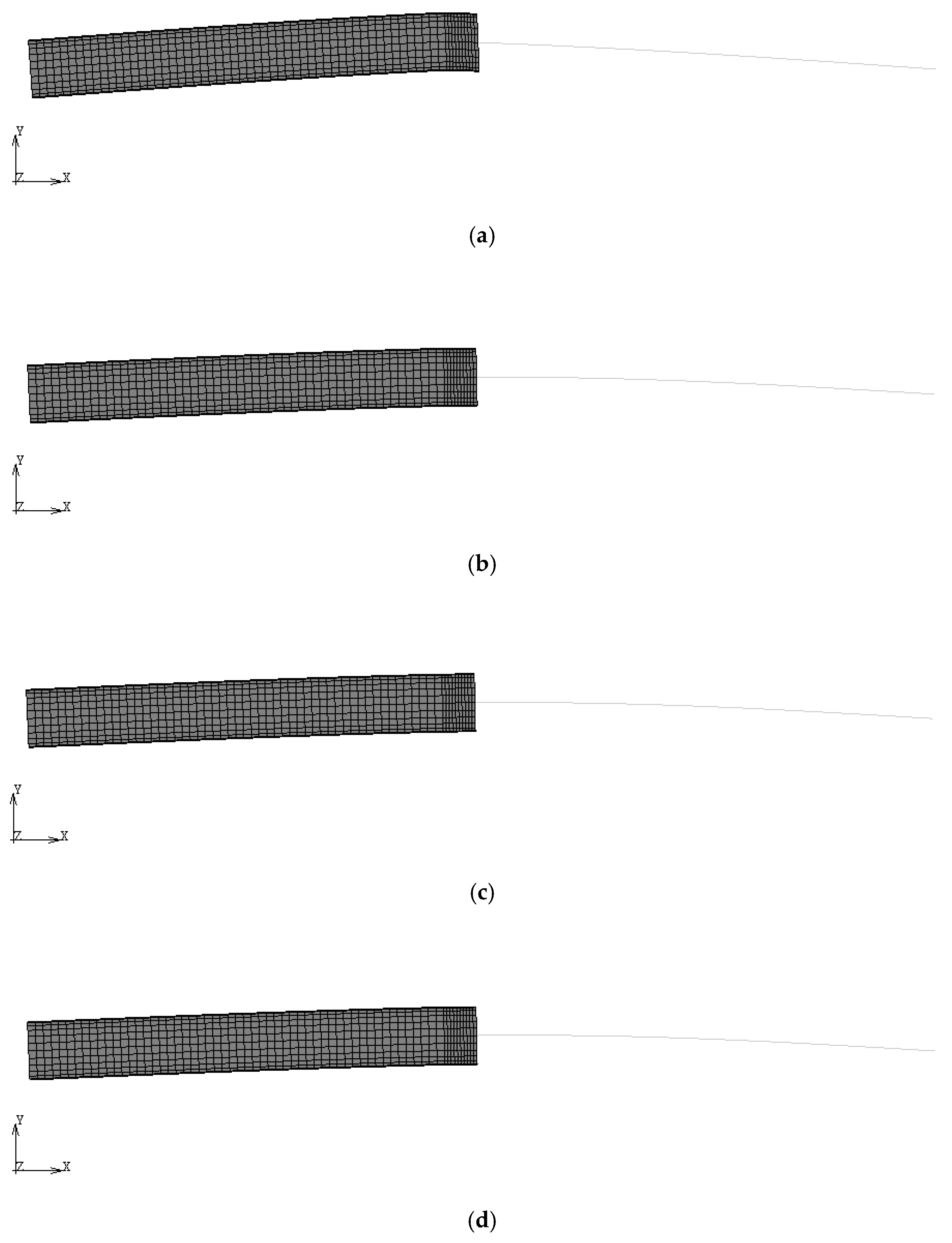
The steel layer was inserted at the cylinder inner radius for Cases B–D and was omitted in the test Case A for comparison, see Table 7. It appears evident from Figure 7 that in the case of the bare 0°/90° stacking sequence, Case B, a local and critical shear deformation occurs between the two rod support points, significantly lowering the buckling critical load with respect to the reference steel assembly (Table 8). For the reference actuator in steel, the pressure at which the buckling occurs is lower than the burst pressure; therefore, for the further FE analyses (e.g., the dynamic forecasts), the models will be loaded at the testing pressure prescribed for this component (42 MPa).
The shear and localized deformation of the cylinder, at the mating area of the cylinder with the piston, could be monitored and reduced by introducing plies with a ±45° orientation angle (ϕ) and by reinstating the steel liner as shown in Figure 8. A local outer reinforcement can also be introduced.
The buckling condition of the reference cylinder is achieved by increasing the liner thickness from 2 mm to 6 mm, and by considering the axial plies from 2.0 mm to 7.0 mm, imposing that the thickness of hoop ply is equal to 5.3 mm.
The weight saving due to the composite choice wears significantly thin, and the overall thickness of the component is comparable to the reference solution and loses the compactness advantage of the Case D solution as shown in Table 7.
A comparison of the total deflection of the connecting point of the cylinder tube and piston rod shows that Case B is more compliant than the reference actuator. However, by increasing the 45° plies, the deflection becomes lower than the reference one, and for Cases C and D, it is almost null.
6.3. The Effect of the Fluid Weight on the Misalignment Actuator Condition
Before applying any loading conditions, one of the main input factors acting in a hydraulic cylinder is the deflection of the cylinder due to its own weight and the fluid weight, [15]. This tiny deflection leads to an initial misalignment on the cylinder tube and piston-rod assembly.
To analyze the influence of the axial pushing load under this misaligned condition, a FE analysis was performed. This simulates the actuator loaded by its own weight and the fluid present in the pressurized chamber, in a pin mounted horizontal configuration, at the pushing load exerted at the testing pressure (42 MPa).
The model setup presented in the previous Section 6.2 has been used. The weight of the fluid was therefore evaluated by referring to the mineral base oil Tellus S2 (ISO VG46), where its density is assumed to be 872 kg/m3. The overall weight of the fluid within the cylinder at the maximum extension of the piston rod thus becomes approximately 132 kg.
Since the density of the oil is known, its weight has been modeled by the evaluating the equivalent nodal forces, acting along the Y-direction, of the cylinder oil chamber discretized by the course mesh, see Figure 7.
The actuator own weight was mimicked by using a gravity and distributed load applied to the elements of the entire model, where the gravity acceleration is imposed equal to 9.81 m/s2 and it acts along the Y-direction.
The buckling FE analysis adopts the boundary conditions previously presented and summarized in Figure 6.
The results obtained for the reference and the composite cylinder Case D are presented below.
The stress field, occurring at the piston rod, due to the cylinder’s own weight and the fluid weight, was evaluated by considering the geometric nonlinearity due to the large rotation hypothesis. In other words, the equilibrium equations are determined by updating the deformed configuration of the structure uploading the stiffness matrix proper of the present FE problem. The pushing load has been gradually increased (100 uniformly spaced steps), and for each load level the Newton–Raphson iteration has been performed up until the relative errors on both the incremental displacements and the residual nodal equilibrium forces fell below the 1‰ threshold.
The bending stress (σMf) and axial stress (σN) values of the rod were calculated by collecting the bending moment and the axial force on the steel rod, for both the reference steel cylinder and the multi-material composite cylinder Case D. The compressive axial stress at the rod is constant on the two configurations and is equal to −163.64 MPa.
Under the assumption of small strain deformation, the hydraulic actuator with the composite cylinder presents a lower bending stress with respect to the reference, approximately −50%. In fact, the decrease in bending stiffness of Case D—raised by the buckling analysis above—is compensated by the reduced weight (approximately −80%). However, due to misaligned axial load, the increase in stress also appears to be relatively small between the actual and the composite solution.
On the other hand, considering the non-linear effect due to the large rotation assumption, the bending moment at the piston-rod increases from 12 MPa up to 37 MPa for the reference configuration, and from 8 MPa up to 45 MPa for the multi-material solution. The bending stress achieves 22.6% and 26.0% of the axial force (σN) for the reference and the composite Case D solution, respectively.
In addition, the bending stress at the rod of Case D is higher than the steel counterpart, and this solution exhibits a more compliant bending deformation as shown in Table 9. In comparison, Figure 8 shows the deformed configuration of the cylinder tube, while pushing under its own and the fluid weight for the linear and non-linear solutions.
6.4. The Dynamic Response
A dynamic modal analysis of the hydraulic cylinder was performed by FE to compare the lateral and bending modal responses of the structure including the fluid weight in a pin-mounted configuration, see Figure 4.
The most promising stacking composite sequence calculated for the buckling critical situation (i.e., Case D) was evaluated for the modal analysis; the mesh quality and the model setup have been analogous to the model presented in Section 6.2, and the density of the materials are summarized in Table 1 and Table 4. The pushing load at the rod free extremity has been omitted for the intrinsic formulation of the modal problem.
The FE simulation shows that the composite (18.13 Hz) has a higher frequency than the steel cylinder (17.26 Hz), since the reduced inertia effect compensates the loss in stiffness.
An additional modal analysis has been performed in cascade to the cylinder deformation state obtained by pre-loading the piston rod with the pushing load at the testing condition. To the best of knowledge, no such models are traced in the pertinent literature.
The first modal shape corresponds to a bending mode; however, the composite solution exhibits the first natural response of structure lower that the reference solution. At this condition, there was a significant decrease in the modal frequency, as shown in the Table 10, due to the misalignment and perturbated deformation state.
In conclusion, Case D is the optimal barrel in composite able to replace the metal reference cylinder.
7. Conclusions
This paper has described a method for designing double-acting hydraulic cylinders with a cylinder barrel made of a carbon fiber composite. This material leads to a significant reduction on weight. In fact, weight is a key feature in various structural applications. Reference properties were calculated using the Lamé’s solution for thick-walled vessels. The equivalent composite cylinder tube and its optimized stacking sequence were evaluated separately considering each component of the stress tensor the cylinder is subjected to.
The hoop stress depends only on the internal pressure, and so do the number and thickness of the circumferential plies. A comparison between different carbon fibers showed that UHM fibers are the most suitable for this specific application. Although resistance mainly depends on the carbon reinforcement, strain is reduced by using an appropriately sized the steel liner. Due to technological and manufacturing limitations, the smallest feasible thickness for the liner is 2 mm.
The axial stress is caused by the internal pressure and bending effects. Although the total thickness depends on the total amount of axial stress, the reciprocal arrangement between the plies at 0° and 90° is due to technological constrains.
With respect to the buckling behavior, four composite stacking sequences were compared to the reference by performing FE simulations. The results of Case D, which also features ± 45° plies in order to confine local deformation, are comparable with the reference.
In conclusion, the composite cylinder was found to be equivalent to the reference cylinder for the modal analysis response.
The weight saved by adopting the cylinder assembly using composite material instead of steel is over 330 kg, ensuring the same structural performance.
Further improvements should focus on the piston-rod design, which affects ~40% of the overall weight of the cylinder assembly. The present methodology and the hydraulic–mechanical efficiency of the cylinder might be validated by performing experimental measurements of the strain field and of the tribological aspect between the seals and the piston-rod; in addition, measurements of buckling occurrence will be required both in laboratory and during actual operations as in [7,8,9,15,41,42], respectively.
Funding
This research received no external funding.
Acknowledgments
The author would like to thank A. Strozzi, E. Bertocchi and E. Dolcini for their technical support during the development of the present research.
Conflicts of Interest
The author declares no conflict of interest.
List of Symbols:
| A0° | minimum cross section area for 0° ply |
| C1, C2 | constant |
| εpeak, εlim | the peak and the limit strain value |
| E | Young’s Modulus for isotropic material |
| E1 | longitudinal Young’s Modulus |
| E2 | transversal Young’s Modulus |
| E3 | radial Young’s Modulus |
| Ef | fibre Young’s Modulus |
| ϕ | orientation angle of the ply |
| G12 | in-plane Shear Modulus |
| G23, G31 | out-of-plane Shear Moduli |
| L | cylinder axial length |
| Lp | piston axial length |
| Lr | rod stroke |
| Λ | scale factor |
| k | number of plies |
| ν12 | major in-lamina plane Poisson’s ratio |
| ν23 | out-of-plane plane Poisson’s ratio |
| ν31 | out-of-plane plane Poisson’s ratio |
| pi | cylinder internal pressure |
| Pa | axial load |
| re | cylinder outer radius |
| rer | rod outer radius |
| ri | cylinder inner radius |
| rir | rod inner radius |
| ρc | density of the ply |
| ρf | fibre density |
| ρm | fibre matrix |
| s | local axis along the cylinder axial extent |
| σ1 | ply tensile strength along the longitudinal direction |
| σMf | bending stress |
| σN | axial stress |
| σr | radial stress |
| σθ | circumferential stress |
| σy | yield stress |
| tϕ | thickness a ϕ oriented ply |
| ur | radial displacement |
| 1, 2, 3 | principal axes of orthotropy |
| r, θ, a | cylindrical coordinate system |
References
- Cuenot, F. CO2 emissions from new cars and vehicle weight in Europe; how the EU regulation could have been avoided and how to reach it? Energy Policy 2009, 37, 3832–3842. [Google Scholar] [CrossRef]
- Tolouei, R.; Titheridge, H. Vehicle mass as a determinant of fuel consumption and secondary safety performance. Transp. Res. Part D Transp. Environ. 2009, 14, 385–399. [Google Scholar] [CrossRef]
- Faruk, O.; Tjong, J.; Sain, M. Lightweight and Sustainable Materials for Automotive Applications; CRC Press, Taylor & Francis Group: Boca Raton, FL, USA, 2017. [Google Scholar]
- Njuguna, J. Lightweight Composite Structures in Transport: Design, Manufacturing, Analysis and Performance; Woodhead Publishing Series in Composites Science and Engineering; Woodhead Publishing: Cambridge, UK, 2016; Volume 67. [Google Scholar]
- Hawkins, T.R.; Gausen, O.M.; Stromman, A.H. Environmental Impacts of Hybrid and Electric—A Review. Int. J. Life Cycle Assess. 2012, 17, 97–1014. [Google Scholar] [CrossRef]
- Kim, N.; Rousseau, A. Assessment by Simulation of Benefits of New HEV Powertrain Configuration. Oil Gas Sci. Technol. Rev. d’IFP Energies Nouv. 2013, 68, 79–93. [Google Scholar] [CrossRef] [Green Version]
- Otte, B.; Stelling, O.; Müller, C. High Pressure Lightweight Hydraulic Fully Composite Piston Accumulators. In Proceedings of the 8th International Fluid Power Conference, Dresden, Germany, 26–28 March 2012. [Google Scholar]
- Solazzi, L. Feasibility study of hydraulic cylinder subject to high pressure made of aluminum alloy and composite material. Compos. Struct. 2019, 209, 739–746. [Google Scholar] [CrossRef]
- Solazzi, L. Design and experimental tests on hydraulic actuator made of composite material. Compos. Struct. 2020, 232. [Google Scholar] [CrossRef]
- Solazzi, L.; Buffoli, A. Telescopic Hydraulic Cylinder Made of Composite Material. Appl. Compos. Mater. 2019, 26, 1189–1206. [Google Scholar] [CrossRef]
- Hunt, T.; Vaughan, N. The Hydraulic Handbook, 9th ed.; Elsevier Advanced Technology: Amsterdam, The Netherlands, 1996. [Google Scholar]
- Speich, H.; Bucciarelli, A. Manuale di oleodinamica: Principi, componenti, circuiti, applicazioni; Tecniche Nuove: Milan, Italy, 2002. [Google Scholar]
- Vullo, V. Circular cylinders and pressure vessels. In Stress Analysis and Design; Springer: Berlin/Heidelberg, Germany, 2014. [Google Scholar]
- Sochacki, W. Modelling and analysis of damped vibration in hydraulic cylinder. Math. Comput. Model. Dyn. Syst. 2015, 21, 23–37. [Google Scholar] [CrossRef]
- Gamez-Montero, P.J.; Salazar, E.; Castilla, R.; Khamashta, M.; Codina, E. Misalignment effects on the load capacity of a hydraulic cylinder. Int. J. Mech. Sci. 2005, 51, 105–113. [Google Scholar] [CrossRef]
- Baragetti, S.; Terranova, A. Bending behaviour of double-acting hydraulic actuator. Proc. Inst. Mech. Eng. Part C J. Mech. Eng. Sci. 2001, 215, 607–619. [Google Scholar] [CrossRef]
- Baragetti, S.; Villa, F. Effects of geometrical clearances, supports friction, and wear rings on hydraulic actuators bending behavior. Math. Probl. Eng. 2016. [Google Scholar] [CrossRef] [Green Version]
- Field, G.J.; Nau, B.S. An experimental study of reciprocating rubber seals. In Proceedings of the IMechE Symposium on Elastohydrodynamic Lubrication; Institution of Mechanical Engineers: London, UK, 1972; pp. 29–36. [Google Scholar]
- Strozzi, A.; Bertocchi, E.; Mantovani, S.; Giacopini, M.; Baldini, A. Analytical evaluation of the peak contact pressure in a rectangular elastomeric seal with rounded edges. J. Strain Anal. Eng. Des. 2016, 51, 304–317. [Google Scholar] [CrossRef]
- Morelli, P. On the Buckling Behaviour of Telescopic Hydraulic Cylinders. In Key Engineering Materials; Trans Tech Publications Ltd.: Red Hook, NY, USA, 2010; Volume 417, pp. 281–284. [Google Scholar] [CrossRef]
- Lie, T.; Chapple, P.J.; Tilley, D.G. Actuator cushion performance simulation and test results. In Proceedings of the Bath Workshop on Power Transmission and Motion Control (PTMC 2000), Bath, UK, 15–18 September 2000; pp. 187–198. [Google Scholar]
- Schwartz, C.; De Negri, V.J.; Climaco, J.V. Modeling and analysis of an auto-adjustable stroke end cushioning device for hydraulic cylinders. J. Braz. Soc. Mech. Sci. Eng. 2005, 27, 415–425. [Google Scholar] [CrossRef] [Green Version]
- Lifshitz, J.M.; Dayan, H. Filament-wound pressure vessel with thick metal liner. Compos. Struct. 1995, 32, 313–323. [Google Scholar] [CrossRef]
- Chapelle, D.; Perreux, D. Optimal design of type 3 hydrogen vessel: Part I—Analytic modelling of the cylindrical section. Int. J. Hydrogen Energy 2006, 31, 627–638. [Google Scholar] [CrossRef]
- Comond, C.; Perreux, D.; Thiebaud, F.; Weber, M. Methodology to improve the lifetime of type III HP tank with a steel liner. Int. J. Hydrogen Energy 2009, 34, 3077–3090. [Google Scholar] [CrossRef]
- Gay, D.; Hoa, S.V.; Tsai, S.W. Composite Materials: Design and Applications, 3rd ed.; CRC Press: Boca Raton, FL, USA, 2015. [Google Scholar]
- Bragohain, M.K. Composite Structures Design, Mechanics, Analysis, Manufacturing and Testing; CRC Press: Boca Raton, FL, USA, 2017. [Google Scholar]
- Thesken, C.; Murthy, P.L.N.; Phoenix, S.L.; Greene, N.; Palko, J.L.; Eldridge, J.; Sutter, J.; Saulsberry, R.; Beeson, H. A Theoretical Investigation of Composite Overwrapped Pressure Vessel (COPV) Mechanics Applied to NASA Full Scale Tests. NASA/TM 215684; 2009. Available online: https://ntrs.nasa.gov/archive/nasa/casi.ntrs.nasa.gov/20090037028.pdf (accessed on 27 December 2019).
- Lanzi, L.; Castelletti, L.M.L.; Anghileri, M. Multi-objective optimisation of composite absorber shape under crashworthiness requirements. Compos. Struct. 2004, 65, 433–441. [Google Scholar] [CrossRef]
- Bisagni, C.; Di Pietro, G.; Fraschini, L.; Terletti, D. Progressive crushing of fiber-reinforced composite structural components of a Formula One racing car. Compos. Struct. 2005, 68, 491–503. [Google Scholar] [CrossRef]
- Gliszczynski, A.; Kubiak, T. Progressive failure analysis of thin-walled composite columns subjected to uniaxial compression. Compos. Struct. 2017, 169, 52–61. [Google Scholar] [CrossRef]
- Sun, G.; Yu, H.; Wang, Z.; Xiao, Z.; Li, Q. Energy absorption mechanics and design optimization of CFRP/aluminium hybrid structures for transverse loading. Int. J. Mech. Sci. 2019, 150, 767–783. [Google Scholar] [CrossRef]
- Timoshenko, S.P.; Goodiesr, J.N. Theory of Elasticity; McGraw-Hill: New York, NY, USA, 1970. [Google Scholar]
- Lempriere, B.M. Poisson’s ratio in orthotropic materials. AIAA J. 1968, 6, 2226–2227. [Google Scholar] [CrossRef]
- Nikas, G.K.; Sayles, R.S. Modelling and optimization of composite rectangular reciprocating seals. Proc. Inst. Mech. Eng. Part J J. Eng. Tribol. 2006, 220, 395–412. [Google Scholar] [CrossRef]
- Nikas, G.K. Eighty years of research on hydraulic reciprocating seals: Review of tribological studies and related topics since the 1930s. Proc. Inst. Mech. Eng. Part J J. Eng. Tribol. 2010, 224, 1–23. [Google Scholar] [CrossRef]
- MSC Team; Mentat, M. User Guide Documentation Vol B: Element Library; MSC Software: Newport Beach, CA, USA, 2015. [Google Scholar]
- Hoblit, F. Critical buckling load for hydraulic actuating cylinders. Prod. Eng. 1950, 21, 108–112. [Google Scholar]
- ISO/TS 13725:2016. Hydraulic Fluid Power-Cylinders: Method for Determining the Buckling Load; International Organization for Standardization: Geneva, Switzerland, 2016. [Google Scholar]
- Cedolin, L. Stability of Structures: Elastic, Inelastic, Fracture and Damage Theories; World Scientific: Singapore, 2010. [Google Scholar]
- Stryczek, P.; Przystupa, F.; Banaś, M. Research on series of hydraulic cylinders made of plastics. In 2018 Global Fluid Power Society PhD Symposium (GFPS); IEEE: Piscataway, NJ, 2018; pp. 1–7. [Google Scholar] [CrossRef]
- Stryczek, J.; Banaś, M.; Krawczyk, J.; Marciniak, L.; Stryczek, P. The fluid power elements and systems made of plastics. Procedia Eng. 2017, 176, 600–609. [Google Scholar] [CrossRef]
Figure 1.
The double-acting hydraulic cylinder assembly.

Figure 2.
The cylindrical coordinate system nomenclature.

Figure 3.
Deformation cycle for liner—composite assembly: (a) a hysteretic loop in an elastic- perfectly plastic liner material, and (b) the limit case of a zero plastic strain energy density loop.
Figure 3.
Deformation cycle for liner—composite assembly: (a) a hysteretic loop in an elastic- perfectly plastic liner material, and (b) the limit case of a zero plastic strain energy density loop.

Figure 4.
Radial displacement at inner radius vs. wall thickness at first-yield pressure.

Figure 5.
Relative radial deformation versus distance from the sealing point.

Figure 6.
Buckling FE model.

Figure 7.
Local buckling deformation of the composite cylinder tube for the test cases named: (a) A, (b) B, (c) C, and (d) D (magnitude factor × 5000).
Figure 7.
Local buckling deformation of the composite cylinder tube for the test cases named: (a) A, (b) B, (c) C, and (d) D (magnitude factor × 5000).

Figure 8.
Deformed configuration (Scale Factor × 50) of the cylinder tube, while pushing under its own weight: (a) reference and (b) composite Case D configuration considering small strain assumption, (c) reference and (d) composite Case D configuration considering large rotation assumption.
Figure 8.
Deformed configuration (Scale Factor × 50) of the cylinder tube, while pushing under its own weight: (a) reference and (b) composite Case D configuration considering small strain assumption, (c) reference and (d) composite Case D configuration considering large rotation assumption.


Table 1.
Material properties for the reference hydraulic actuator.
| Material | Ultimate Strength [MPa] | Yield Strength [MPa] | Young Modulus [MPa] | Density [kg/dm3] |
|---|---|---|---|---|
| Aluminium, 7057-T6 | 510 | 500 | 70,000 | 2.7 |
| Steel, 42CrMo4 | 900 | 550 | 210,000 | 7.8 |
| Steel, S355 | 550 | 355 | 210,000 | 7.8 |
Table 2.
Weight of the reference hydraulic cylinder parts.
| ID Label | Component | Material | Weight [kg] | % Weight |
|---|---|---|---|---|
| 1 | Rod | Steel, 42CrMo4 | 321 | 39.8% |
| 2 | Head | Aluminum, 7057-T6 | 30 | 3.7% |
| 3 | Cylinder Tube | Steel, S355 | 408 | 50.6% |
| 4 | Piston | Aluminum, 7057-T6 | 24 | 2.9% |
| 5 | End cap | Steel, S355 | 24 | 3.0% |
| Overall weight | - | 807 | 100% |
Table 3.
Reference cylinder tube stress and radial deformation at the first-yield.
| Reference Cylinder Tube | Structural Properties |
|---|---|
| pi | 67 MPa |
| σθ|r = ri | 483 MPa |
| ur|r = ri | 0.359 mm |
Table 4.
The reinforcements and the matrix properties.
| Continuous Reinforcement | Tensile Modulus Ef [MPa] | Tensile Strength σf [MPa] | Density ρf [g/cm3] |
|---|---|---|---|
| Intermediate Modulus (IM) Carbon Fibre | 300,000 | 5500 | 1.80 |
| High Modulus (HM) Carbon Fibre | 440,000 | 4200 | 1.85 |
| Ultra High Modulus (UHM) Carbon Fibre | 620,000 | 3500 | 2.12 |
| Matrix | Tensile Modulus Em [MPa] | Tensile Strength σm [MPa] | Density ρm [g/cm3] |
| Epoxy | 3800 | 100 | 1.22 |
Table 5.
The elastic properties of the unidirectional (UD) composite ply referred to the principal directions of the lamina.
Table 5.
The elastic properties of the unidirectional (UD) composite ply referred to the principal directions of the lamina.
| Lamina | Elastic Modulus || to the Fibre Direction, E1 | Elastic Modulus ꓕ to the Fibre Direction, E2 | In-Plane Shear Modulus, G12 | Major Poisson Ratio, ν12 | Longitudinal Tensile Strength, σ1 | Density, ρc |
|---|---|---|---|---|---|---|
| Intermediate Modulus (IM) Carbon Fibre | 147,000 | 6870 | 3800 | 0.27 | 1500 | 1.50 |
| High Modulus (HM) Carbon Fibre | 235,000 | 6800 | 4000 | 0.27 | 1709 | 1.52 |
| Ultra High Modulus (UHM) Carbon Fibre | 380,000 | 6200 | 4090 | 0.27 | 2000 | 1.76 |
Table 6.
The three design constraints discussed in the present paragraph, for summarizing purposes.
| Design Constraint | Inequality Formulation | Prevented Failures | Notes |
|---|---|---|---|
| Upper limit on the circumferential stress value | Fracture of the circumferential lamina | from Equation (5) from Table 5 | |
| Upper limit on the inner radial displacement | Excessive leakage or piston misalignment | from Equation (6) from seal manufacturer requirements | |
| Upper limit on the inner circumferential strain | Low-cycle fatigue fractures of the steel layer in the longitudinal direction | from Equation (6) from Equation (8) |
Table 7.
The thickness of plies and of the inner liner subdivided by orientation angle ϕ, adopted for the test cases studied for the composite cylinder tube.
Table 7.
The thickness of plies and of the inner liner subdivided by orientation angle ϕ, adopted for the test cases studied for the composite cylinder tube.
| Case | t 0° [mm] | t 90° [mm] | t ±45° [mm] | t liner [mm] |
|---|---|---|---|---|
| A | 2.0 | 5.3 | 0.0 | no liner |
| B | 2.0 | 5.3 | 0.0 | 2.0 |
| C | 2.0 | 5.3 | 2.0 | 2.0 |
| D | 2.0 | 5.3 | 4.0 | 2.0 |
Table 8.
The result of buckling analysis.
| Case | Cylinder Tube Radial Thickness [mm] | Weight [kg] | Critical Pressure [MPa] | Maximum Rod Deflection [mm] |
|---|---|---|---|---|
| A | 7.3 | 29 | 18.4 | 0.029 |
| B | 9.3 | 63 | 43.8 | 0.018 |
| C | 11.3 | 72 | 48.9 | 0.000 |
| D | 13.3 | 80 | 51.1 | 0.000 |
| Reference | 22.5 | 408 | 60.3 | 0.013 |
Table 9.
The stress values and maximum deflection at the rod.
| Case | σMf Considering Small Strain Assumption [MPa] | σMf Considering Large Rotation, Non-Linear Condition [MPa] | Max. Piston-Rod Deflection, Small Strain Condition [mm] | Max. Piston-Rod Deflection, Non-Linear Condition [mm] |
|---|---|---|---|---|
| D | ±7.98 | ±45.15 | −0.95 | −5.24 |
| Reference | ±12.14 | ±36.94 | −1.11 | −3.59 |
Table 10.
The modal response of the actuator considering or neglecting the initial deformation due the pushing load.
Table 10.
The modal response of the actuator considering or neglecting the initial deformation due the pushing load.
| Case | 1st Frequency, Modal Analysis [Hz] | 1st Frequency Considering the Preloaded Configuration [Hz] |
|---|---|---|
| Reference | 17.26 | 9.58 |
| D | 18.13 | 7.66 |
© 2020 by the author. Licensee MDPI, Basel, Switzerland. This article is an open access article distributed under the terms and conditions of the Creative Commons Attribution (CC BY) license (http://creativecommons.org/licenses/by/4.0/).
Share and Cite
MDPI and ACS Style
Mantovani, S. Feasibility Analysis of a Double-Acting Composite Cylinder in High-Pressure Loading Conditions for Fluid Power Applications. Appl. Sci. 2020, 10, 826. https://doi.org/10.3390/app10030826
AMA Style
Mantovani S. Feasibility Analysis of a Double-Acting Composite Cylinder in High-Pressure Loading Conditions for Fluid Power Applications. Applied Sciences. 2020; 10(3):826. https://doi.org/10.3390/app10030826
Chicago/Turabian StyleMantovani, Sara. 2020. "Feasibility Analysis of a Double-Acting Composite Cylinder in High-Pressure Loading Conditions for Fluid Power Applications" Applied Sciences 10, no. 3: 826. https://doi.org/10.3390/app10030826
Note that from the first issue of 2016, this journal uses article numbers instead of page numbers. See further details here.