Tar Removal by Nanosecond Pulsed Dielectric Barrier Discharge


Institute of Fluid Flow Machinery, Polish Academy of Sciences, 80231 Gdańsk, Poland
*
Author to whom correspondence should be addressed.
Appl. Sci. 2020, 10(3), 991; https://doi.org/10.3390/app10030991
Submission received: 30 December 2019
/
Revised: 28 January 2020
/
Accepted: 31 January 2020
/
Published: 3 February 2020
(This article belongs to the Special Issue The Applications of Plasma Techniques)
Abstract
:Featured Application
Biogas and biomass producer gas cleaning.
Abstract
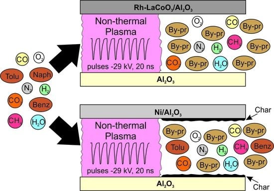
Plasma-catalytic reforming of simulated biomass tar composed of naphthalene, toluene, and benzene was carried out in a coaxial plasma reactor supplied with nanosecond high-voltage pulses. The effect of Rh-LaCoO3/Al2O3 and Ni/Al2O3 catalysts covering high-voltage electrode on the tar conversion efficiency was evaluated. Compared to the plasma reaction without a catalyst, the combination of plasma with the catalyst significantly enhanced the conversion of all three tar components, achieving complete conversion when an Rh-based catalyst was used. Apart from gaseous and liquid samples, char samples taken at five locations inside the reactor were also analyzed for their chemical composition. Char was not formed when the Rh-based catalyst was used. Different by-products were detected for the plasma reactor without a catalyst, with the Ni- and Rh-based catalysts. A possible reaction pathway in the plasma-catalytic process for naphthalene, as the most complex compound, was proposed through the combined analysis of liquid and solid products.
1. Introduction
Tars formed during biomass gasification are an important problem for installations located downstream of the gasification reactor. They cause clogging of pipes and valves and damage to engine and turbine components. For that reason, there are limits recommended separately for various applications such as <100 mg/m3, <5 mg/m3, and <1 mg/m3 for internal combustion engines, gas turbines and fuel cells, respectively [1]. This means that the concentration of tars must be drastically reduced before application since their amount in the biomass producer gas is typically in the range of 1–150 g/m3 [2].
There are many methods to purify gas of tars [1,2,3]. Among the methods, the most attractive are those that enable the transformation of undesirable tars into components that increase its energy and chemical value. These include catalytic cracking and hydrocracking of light hydrocarbon tars, dry or steam reforming of tars into carbon monoxide and hydrogen, thermal cracking, leaching in suitable solvents, and plasma methods.
The plasma used to purify the gas from biomass gasification is generated by various types of electrical discharges. Its advantage is instant high gas temperature and high reactivity due to the presence of energetic electrons, ions, and radicals. The largest amount of research is related to arc, dielectric barrier, corona and microwave discharges and their combinations with catalytic materials [4,5,6,7,8,9,10,11,12,13,14,15,16,17]. An excellent review of the application of plasma-catalyst systems for tar removal was presented in [18] and most recent [19].
In this work, a dielectric barrier discharge (DBD) reactor combined with catalytic materials was used. DBD reactors are considered to be very attractive for heavy hydrocarbon cracking due to the high electron density and energy, plasma homogeneity, simple design and operation, capacity to induce reactions at relatively ambient temperature, atmospheric operational pressure, and very low level of coke production [20]. The novelty of this work lies in the combination of four problems that have so far been studied independently or in a smaller combination, i.e.,:
- Number of tar components—in this work 3 tar representatives were used together while in most cases only 1 or 2 are used [11,15,16,22,23,24,25,26,27,28,29,30,31,32,33,34]. Excluding a few works performed on real biomass producer gas [9,14,21] only Kong et al. [17], Eliott et al. [10], Jamroz et al. [12] and Yu et al. [35] used at least 3 tar components, but in nitrogen, argon and oxygen as a plasma-forming gas;
- DBD plasma with a catalyst—this has been studied by many researchers [18] and is called a one-stage configuration since the catalytic material is in contact with the plasma. The advantage of this configuration is the use of radicals, which are formed in the plasma and which have a very short lifetime;
- Nanosecond high-voltage pulses—investigations have shown that shortening high-voltage pulse leads to increasing the formation of highly energetic electrons, ions, radicals and exited molecules at the same input power [36]. Such short pulses were used for tar removal only by researchers from Eindhoven University of Technology in pulsed corona discharge reactors [4,5,6,7].
2. Materials and Methods
2.1. Non-Thermal Plasma Reactor and Processed Gas
The reactor is made of an Al2O3 ceramic cylinder (length of 150 mm, inner and outer diameter of 16 mm and 20 mm, respectively) which is wrapped with copper foil connected electrically to the ground (Figure 1). Inside the cylinder, a brass tube operating as a high-voltage electrode and gas provider is placed coaxially. This electrode is covered first with a tube made of porous reticulated vitreous carbon (RVC) and then with a porous Al2O3 ceramic tube so that the gas gap between two ceramic tubes is 2 mm. The task of the RVC tube is to work as a high-voltage electrode and to transmit gas towards the porous ceramics. The whole reactor, including gas inlet and outlet, is placed in a furnace heated to 300 °C.
As a source of nanosecond pulses, we used an NPG-15/2000 pulse generator by Megaimpulse Ltd., producing negative voltage pulses of 29 kV with a repetition rate in the range of 50 Hz–3.0 kHz. This power source implies the use of voltage and current measurement typical for pulsed corona discharge. The voltage pulses were measured using a Tektronix P6015A high-voltage probe, whereas the current pulses were measured using a Pearson 2877 coil. The single discharge pulse energy (Ep), was obtained after the experiment by the integration of the pulse voltage (U) times the current (I) over the pulse duration (t):
The specific energy input (SEI) is usually used as a variable in experiments with non-thermal plasma reactors. In this case, it was calculated from a formula:
where f is the pulse repetition rate in Hz, and Q is the gas flow rate in L/s at standard conditions.
All experiments were performed with a constant flow rate of 0.2 L/min (residence time 3.9 s) of the operating gas, which was a dry biomass producer gas simulator CH4(2.5%):CO2(11%): H2(14%):CO(21.5%):N2(51%) to which water vapor and the main compounds of wood tar, i.e., benzene, toluene, and naphthalene [9], were added. Water vapor was added by injecting distilled water from a syringe pump into the hot gas line inside the furnace. The aromatic hydrocarbons dissolved in isopropanol were then added in the same way. The resulting composition of the inlet gas was as follows: CH4(2%):CO2(9%):H2(12%):CO(18%):N2(42%):H2O(17%) with 10 g/m3 of tar (58% benzene, 3% toluene, 39% naphthalene).
2.2. Catalyst Preparation
Excluding the first series of experiments, which were conducted without a catalytic material, the rest used one of two catalysts: Al2O3 supported Rh-LaCoO3 and Ni/Al2O3. As a catalyst support, both ceramic tubes of the reactor were used so that inner ceramic tube was completely impregnated with a catalyst, whereas the outer ceramic cylinder was covered with catalytic material only on the inner surface.
The rhodium promoted La-CoO3 catalyst was prepared by wet impregnation, dissolving stoichiometric amounts of La(NO3)3∙H2O (Sigma-Aldrich, >99.9%) and Co(NO3)2∙6H2O (Sigma-Aldrich, ≥98%) in a water solution containing the ceramic tubes and a few drops of nitric acid [37]. The solution was completely evaporated and then the ceramic tubes were dried for 2 h at 120 °C. Calcination was carried out at 800 °C for 3 h with an air flow of 150 mL min−1 and heating rate of 10 °C min−1. The calcined ceramic tubes were further impregnated with a Rh(NO3)3∙H2O (Sigma-Aldrich) solution using an amount of rhodium corresponding to 1 %wt., then drying and calcination were repeated. In the next section, this compound will be noted as Rh/LaCoO3/Al2O3. Resulting weight hourly space velocity (WHSV) was 0.54 h−1.
The Ni-based catalyst was prepared by wet impregnation of the ceramic tubes in an Ni(NO3)2∙6H2O (Sigma-Aldrich, >99.9%) water solution, followed by drying and calcination under the same conditions as described above. WHSV was 0.63 h−1.
2.3. Diagnostics of Products
For tar sampling and analysis, the standard tar protocol developed by Energy Research Center of the Netherlands (ECN) was used [38,39]. A portion of the gas leaving the reactor flowed through 6 impinger bottles containing isopropanol. The first 4 bottles were cooled with water (20 °C) whereas the 2 others were immersed in a salt and ice bath (−20 °C). The condensable products dissolved in the isopropanol were analyzed using a GC–MS (Shimadzu GCMS-TQ8030 with HP-5MS column, carrier gas: helium).
The gas leaving the last impinger bottle was collected in a sampling bag and then analyzed using Shimadzu GC-2014 (detectors: FID and TCD, column: 40/60 Carboxen 1000, carrier gas: He) and SRI 8610C (detector: TCD, column: molecular sieve 5A, carrier gas: Ar) gas chromatographs. The calibration carried out previously made it possible to determine the concentrations of H2, O2, N2, CO, CO2, CH4, C2H2, C2H4, and C2H6.
The char deposited in the DBD reactor was analyzed by the FTIR-ATR technique. For this purpose, a Thermo Scientific Nicolet 380 FTIR spectrometer and GladiATR with diamond crystal from Pike Technologies was used.
3. Results and Discussion
3.1. Nanosecond Pulsed Corona Discharge Characteristics
A typical voltage pulse is presented in Figure 2. It does not depend on the reactor geometry, condition of the dielectric barrier, presence of catalysts, or gas composition. Its half-measured width is 9 ns, which ensures fast energization of electrons and inhibits their thermalization. This way, energy delivered to the discharge is not wasted in gas heating but consumed by electrons and further the production of radicals via electron-induced dissociation of molecules.
Current pulses are influenced strongly by the discharge environment. When the internal ceramic barrier is impregnated with catalytic material, the current pulse is much higher compared to clean ceramics (Figure 3). This difference was expected, since a catalyst is formed by metals conducting an electric current and inhibiting the effect of the ceramic barrier. It also strongly influences the discharge energy, resulting in higher values when treating the gas mixture in the reactor with the catalyst (Figure 4). As can be seen in Figure 4, the pulse energy also grows with the pulse repetition rate. This is the result of remaining charged species in gas space between two consecutive pulses. At high pulse repetition rate, they do not have sufficient time to diffuse and recombine. Moreover, each pulse increase concentration of long-living metastable species formed in the process of electron-impact excitation, which is beneficial for the multi-step ionization for the next pulse.
3.2. Tar Removal
The results of the destruction of the tar components in the biomass producer gas simulator are presented in Figure 5. They suggest that the catalysts are activated even though the gas temperature is much lower than required by classical catalytic processes. In the presence of the Rh-based catalyst, all three tar components can be completely removed from the processed gas at the highest discharge energy. In the case of the Ni catalyst, only naphthalene disappeared while traces of toluene and benzene remained. Non-thermal plasma alone can destruct benzene, toluene, and naphthalene, but with lower efficiency than in a reactor containing catalysts. As can be seen in Figure 5, the Rh-based catalyst exhibits higher activity in these conditions compared to the Ni catalyst. This is in agreement with an experiment of Amendola et al. [37] showing that the Ni/Al2O3 had a lower tar reforming activity than an Rh/LaCoO3/Al2O3 catalyst.
When concentrations are presented as logarithms (Figure 6), it can be seen that they are typical for a first order reaction, with the difference that the time parameter is replaced by energy. This means that tar removal depends exponentially on the discharge energy and is driven by radical linear termination [4]. Most of the radicals are formed via electron collisions with molecules of the main gas components, i.e., N2, CO2, H2, CO, H2O, and CH4. From all resulting radicals, only O, H, and OH play an important role in tar decomposition. As was proven by Pemen et al. [4], the dominant mechanism of tar removal in biomass producer gas treated by non-thermal plasma is oxidation by O radicals. Bityurin et al. [40] claim that also H radicals highly contribute to the naphthalene decomposition. The same conclusion may be drawn from an analysis of the results presented in Figure 5. One can notice that the concentration of naphthalene decreases faster than the two other tar components, and toluene removal is a little bit faster than benzene. It is worth noting that the rate constant of the reaction of O radicals with naphthalene at 250 °C is almost 2 and 4 times higher than for toluene and benzene, respectively [41]:
Naphthalene + O → products, k = 4.13 × 10⁻¹² cm3/molecule s,
Toluene + O → products, k = 9.27 × 10⁻¹³ cm3/molecule s,
Benzene + O → products, k = 5.11 × 10⁻¹³ cm3/molecule s.
Reaction of naphthalene with H radicals is even faster than with O atoms and its rate constant at 250 °C is much higher than for toluene and benzene [41]:
Naphthalene + H → products, k = 3.83 × 10⁻⁹ cm3/molecule s,
Toluene + H → products, k = 1.37 × 10⁻¹³ cm3/molecule s,
Benzene + H → products, k = 2.71 × 10⁻¹¹ cm3/molecule s.
However, neither O nor H radicals are leading in the tar decomposition reactions. Due to the large amount of nitrogen molecules in the simulated producer gas the main reactions are those with N2(A3∑) excited molecules [40,42]. Unfortunately, in such a complex mixture as the biomass producer gas, there are many processes that are competitive to useful reactions with excited nitrogen molecules, O and H radicals. Other constituents of the producer gas, in particular CO and CO2, are responsible for both the production and termination of radicals decomposing tar components. Complete picture of chemical kinetics is very complex and requires numerical modeling for detailed analysis. Unfortunately, rate constants for many reactions of tar derivatives with radicals formed in plasma are not known which makes all theoretical considerations speculative.
There is also an energy aspect of the tar removal. Discharge pulse characteristics makes SEI values achieved in this work much higher than in non-thermal plasma systems used by other researchers. Here SEI is in the range 35–7542 J/L whereas Nair et al. [7] obtained 500 J/L in the pulsed corona discharge reactor, Xu et al. [42] reached 768 J/L in the packed-bed DBD reactor, and Mei et al. [43] used 972 J/L in the gliding arc discharge reactor. Such a big difference can give the impression that a lot of energy is lost in the nanosecond pulsed DBD reactor. However, none of the above works was carried out in such a complex mixture which is very close to the real biomass producer gas. As was mentioned in the Introduction, only Marias et al. [9], Materazzi et al. [21] and Wnukowski et al. [14] have tested plasma application for tar removal from real biomass producer gas. The latter gives SEI value of 5184 J/L at which almost all tar compounds were completely converted. Thus, full tar conversion in the producer gas requires high SEI in the range of several thousand J/L.
3.3. Gaseous Compounds
Complete destruction of benzene, toluene, and naphthalene introduced into the studied DBD reactor may provide the hydrogen equivalent of 0.54%, 0.031% and 0.29%, respectively. Altogether, it provides up to 0.861% of additional hydrogen. This figure corresponds with an increase of H2 concentration in the case of the reactor with the Rh catalyst (Figure 7a). As expected, application of the Ni catalyst leads to a lower increase in hydrogen concentration, whereas the absence of a catalyst results in insignificant hydrogen production. A similar relationship was observed in the concentration of methane (Figure 7b). Generally, it can be concluded that hydrogen and methane introduced into the reactor as components of the gaseous phase are not transformed in the nanosecond DBD plasma. A similar phenomenon was observed by Marias et al. [9] in a plasma torch reactor.
The concentrations of CO2 and CO also depend on the presence and type of catalyst, and they follow an order: Rh catalyst > Ni catalyst > no catalyst (Figure 8a,b). In contrast to the H-containing components of the biomass producer gas simulator, carbon dioxide decomposes significantly in the nanosecond DBD plasma. The CO2 concentration decreases almost linearly with the discharge energy causing an adequate increase in CO concentration. This phenomenon has been observed by many researchers in diverse non-thermal plasma sources, such as DBD [44,45], gliding arc [46,47] and microwave discharge [48,49]. It was found that high energy electrons in these electrical discharges induce vibrational excitation of CO2 molecules, which is a highly efficient channel for CO2 decomposition [50]. This is also the reason for the decrease in energy efficiency of each plasma driven hydrocarbon reforming in the presence of CO2.
3.4. Analysis of Liquid and Solid By-products
In the case of the DBD reactor with the Rh catalyst and the highest discharge energy applied (7542 J/L), no liquid by-products were found. This means complete conversion of all tar components into gases. A similar result was found by Liu et al. [51] during oxidation of benzene in a packed-bed DBD reactor after adsorption on a catalyst. In all other cases, i.e., at a lower discharge energy, with an Ni catalyst and without a catalyst, a wide range of liquid by-products were detected. Those of a single aromatic ring (phenol, hydroquinone, 1,4-benzoquinone, 4-phenoxyphenol, o-phthalaldehyde, benzaldehyde, and benzyl), and an aliphatic or cyclic structure (maleic anhydride, methanol, heptanoic acid, acetic acid and formic acid) can be attributed to the oxidation of all three tar components introduced to the reactor. Four compounds derived exclusively from naphthalene have also been detected: phthalic anhydride, 1,4-naphthoquinone, 1-naphthol, and 2-naphthol. They were also all detected by other researchers in different studies concerning tar removal in plasma-catalytic systems [4,26,27,28,29,33,51]. In the case of the Ni catalyst incorporated in the inner ceramic tube, no aliphatic products were detected.
When an Ni or catalyst-free reactor was used, char formation on the inner ceramic tube was observed. It caused fast deactivation of the catalyst. No char was observed only when the Rh catalyst was used, even at lower discharge energies. Then, also no deactivation was observed for 6 h of total use of Rh catalyst. In the case of the reactor with the Ni catalyst, an interesting result concerning char composition was obtained. The amount of char was enough to perform FTIR-ATR analysis. Samples were taken at five equally spaced points along the inner ceramic tube. Usually, as in the work of Cimerman et al. [28], the identification of the exact decomposition by-products of naphthalene alone by using FTIR spectroscopy, especially those in the solid phase, is not trivial. Then, often only functional groups can be determined. However, as can be seen in Figure 9, the spectra are not very complex which allowed to identify all components basing on FTIR spectra libraries. This was carried out using Thermo Scientific™ OMNIC™ Spectra Software with library analysis tool. It was found that spectra presented in Figure 9 is the sum of at most seven components. The first point of sampling, named Char1, was located just a few centimeters from the inlet to the reactor, thus it is not surprising that the spectra is dominated with naphthalene. In this sample, small amounts of naphthols and 1,4-naphthoquinone were also recognized. In the spectra of the second sample, named Char2, bands originated from naphthalene are lower whereas those from naphthols and 1,4-naphthoquinone are higher and a band from phthalic anhydride appeared. The third sample, named Char3, shows a further decrease in naphthalene concentration, but also a decrease in the concentration of naphthols. Bands derived from 1,4-naphthoquinone and phthalic anhydride increased and additional bands from maleic anhydride and 1,4-benzoquinone appeared in the spectra. In the next sample, named Char4, there is no more naphthalene, and the concentration of naphthols continue to decrease. Moreover, it is seen that the band from 1,4-naphthoquinone is lower than in the previous sample and bands typical for 1,4-benzoquinone, phthalic anhydride, and maleic anhydride are higher. In the last sample, named Char5, there are only traces of naphthols and 1,4-naphthoquinone, a decreased amount of phthalic anhydride and an increased amount of maleic anhydride and 1,4-benzoquinone.
Based on the changes in the spectra of the char samples described above, a general scheme of naphthalene conversion can be proposed, as shown in Figure 10. In this scheme, benzene is an intermediate, but it is also a substrate since it enters the reactor together with naphthalene and toluene. It is not clear at the moment why maleic anhydride and 1,4-benzoquinone were found in the char samples whereas benzene and phenol were not.
As mentioned above, char formation was also observed in the case of the catalyst-free reactor. However, FTIR-ATR analysis resulted in spectra so complex that it was impossible to identify all compounds and consequently no tar conversion mechanism can be proposed on this basis.
4. Conclusions
The application of a DBD reactor supplied with nanosecond high-voltage pulses and containing catalysts for tar removal from biomass producer gas was studied. The experiment was focused on the conversion efficiency of three heavy hydrocarbons always present in real gas produced in biomass gasification: naphthalene, toluene, and benzene. Ni- and Rh-based catalysts were used separately as impregnation in the ceramic barrier of the reactor. This way, non-thermal plasma induces surface catalytic reactions resulting in tar conversion, which reached 100% when the Rh-based catalyst was used. This catalyst also allowed char formation to be avoided, which was observed when the Ni catalyst was used, as well as in the reactor without any catalytic material.
Analysis of the gaseous components shows that in the case of the Rh-based catalyst, all heavy hydrocarbons were transformed into simple gases such as those being the main components of biomass producer gas, i.e., CO, CO2, CH4, and H2. The highest resulting turnover frequency (TOF) was 1.57 × 10⁻⁴ s−1. Application of the Ni catalyst led to a lower tar conversion, and consequently to a lower increase in hydrogen concentration. Thus, the highest TOF for this catalyst was 1.55 × 10⁻⁴ s−1. As for the main gaseous components, it can be concluded that hydrogen and methane introduced into the reactor are not transformed in the nanosecond DBD plasma. On the other hand, the CO2 concentration decreases almost linearly with the discharge energy, causing an adequate increase in CO concentration, which is typical behavior for non-thermal plasma reactors.
Although the energy efficiency of the studied nanosecond DBD combined with a catalyst impregnated in the ceramic inner barrier is not superior compared to non-thermal plasma systems developed by other researchers, the results presented in this paper show that such a one-stage configuration is a proper direction of research and the key factor is the catalytic material.
Author Contributions
Conceptualization, M.D.; methodology, M.D. and D.K.; validation, M.D. and D.K.; formal analysis, M.D.; investigation, M.D. and D.K.; writing—original draft preparation, M.D.; writing—review and editing, M.D.; visualization, D.K. All authors have read and agreed to the published version of the manuscript.
Funding
This research received no external funding.
Conflicts of Interest
The authors declare no conflict of interest.
References
- Valderrama Rios, M.L.; González, A.M.; Lora, E.E.S.; Almazán del Olmo, O.A. Reduction of tar generated during biomass gasification: A review. Biomass Bioenergy 2018, 108, 345–370. [Google Scholar] [CrossRef]
- Asadullah, M. Biomass gasification gas cleaning for downstream applications: A comparative critical review. Renew. Sustain. Energy Rev. 2014, 40, 118–132. [Google Scholar] [CrossRef]
- Anis, S.; Zainal, Z.A. Tar reduction in biomass producer gas via mechanical, catalytic and thermal methods: A review. Renew. Sustain. Energy Rev. 2011, 15, 2355–2377. [Google Scholar] [CrossRef]
- Pemen, A.J.M.; Nair, S.A.; Yan, K.; Van Heesch, E.J.M.; Ptasinski, K.J.; Drinkenburg, A.A.H. Pulsed Corona Discharges for Tar Removal from Biomass Derived Fuel Gas. Plasmas Polym. 2003, 8, 209–224. [Google Scholar] [CrossRef]
- Nair, S.A.; Pemen, A.J.M.; Yan, K.; Van Gompel, F.M.; Van Leuken, H.E.M.; Van Heesch, E.J.M.; Ptasinski, K.J.; Drinkenburg, A.A.H. Tar removal from biomass-derived fuel gas by pulsed corona discharges. Fuel Process. Technol. 2003, 84, 161–173. [Google Scholar] [CrossRef]
- Nair, S.A.; Yan, K.; Pemen, A.J.M.; Winands, G.J.J.; van Gompel, F.M.; van Leuken, H.E.M.; van Heesch, E.J.M.; Ptasinski, K.J.; Drinkenburg, A.A.H. A high-temperature pulsed corona plasma system for fuel gas cleaning. J. Electrostat. 2004, 61, 117–127. [Google Scholar] [CrossRef]
- Nair, S.A.; Yan, K.; Pemen, A.J.M.; Van Heesch, E.J.M.; Ptasinski, K.J.; Drinkenburg, A.A.H. Tar Removal from Biomass-Derived Fuel Gas by Pulsed Corona Discharges. A Chemical Kinetic Study. Ind. Eng. Chem. Res. 2004, 43, 1649–1658. [Google Scholar] [CrossRef]
- Fourcault, A.; Marias, F.; Michon, U. Modelling of thermal removal of tars in a high temperature stage fed by a plasma torch. Biomass Bioenergy 2010, 34, 1363–1374. [Google Scholar] [CrossRef]
- Marias, F.; Demarthon, R.; Bloas, A.; Robert-Arnouil, J.P. Modeling of tar thermal cracking in a plasma reactor. Fuel Process. Technol. 2016, 149, 139–152. [Google Scholar] [CrossRef]
- Eliott, R.M.; Nogueira, M.F.M.; Silva Sobrinho, A.S.; Couto, B.A.P.; MacIel, H.S.; Lacava, P.T. Tar reforming under a microwave plasma torch. Energy Fuels 2013, 27, 1174–1181. [Google Scholar] [CrossRef]
- Wnukowski, M. Decomposition of Tars in Microwave Plasma–Preliminary. J. Ecol. Eng. 2014, 15, 23–28. [Google Scholar]
- Jamróz, P.; Kordylewski, W.; Wnukowski, M. Microwave plasma application in decomposition and steam reforming of model tar compounds. Fuel Process. Technol. 2018, 169, 1–14. [Google Scholar] [CrossRef]
- Wnukowski, M.; Jamróz, P. Microwave plasma treatment of simulated biomass syngas: Interactions between the permanent syngas compounds and their influence on the model tar compound conversion. Fuel Process. Technol. 2018, 173, 229–242. [Google Scholar] [CrossRef]
- Wnukowski, M.; Kordylewski, W.; Łuszkiewicz, D.; Leśniewicz, A.; Ociepa, M.; Michalski, J. Sewage Sludge-Derived Producer Gas Valorization with the Use of Atmospheric Microwave Plasma. Waste Biomass Valorization 2019, 2019, 1–15. [Google Scholar] [CrossRef] [Green Version]
- Medeiros, H.S.; Pilatau, A.; Nozhenko, O.S.; Da Silva Sobrinho, A.S.; Petraconi Filho, G. Microwave Air Plasma Applied to Naphthalene Thermal Conversion. Energy Fuels 2016, 30, 1510–1516. [Google Scholar] [CrossRef]
- Nunnally, T.; Tsangaris, A.; Rabinovich, A.; Nirenberg, G.; Chernets, I.; Fridman, A. Gliding arc plasma oxidative steam reforming of a simulated syngas containing naphthalene and toluene. Int. J. Hydrog. Energy 2014, 39, 11976–11989. [Google Scholar] [CrossRef]
- Kong, X.; Zhang, H.; Li, X.; Xu, R.; Mubeen, I.; Li, L.; Yan, J. Destruction of toluene, naphthalene and phenanthrene as model tar compounds in a modified rotating gliding arc discharge reactor. Catalysts 2019, 9, 19. [Google Scholar] [CrossRef] [Green Version]
- Liu, L.; Zhang, Z.; Das, S.; Kawi, S. Reforming of tar from biomass gasification in a hybrid catalysis-plasma system: A review. Appl. Catal. B Environ. 2019, 250, 250–272. [Google Scholar] [CrossRef]
- Saleem, F.; Harris, J.; Zhang, K.; Harvey, A. Non-thermal plasma as a promising route for the removal of tar from the product gas of biomass gasification-A critical review. Chem. Eng. J. 2020, 382, 122761. [Google Scholar] [CrossRef]
- Rahimpour, M.R.; Jahanmiri, A.; Mohamadzadeh Shirazi, M.; Hooshmand, N.; Taghvaei, H. Combination of non-thermal plasma and heterogeneous catalysis for methane and hexadecane co-cracking: Effect of voltage and catalyst configuration. Chem. Eng. J. 2013, 219, 245–253. [Google Scholar] [CrossRef]
- Materazzi, M.; Lettieri, P.; Mazzei, L.; Taylor, R.; Chapman, C. Reforming of tars and organic sulphur compounds in a plasma-assisted process for waste gasification. Fuel Process. Technol. 2015, 137, 259–268. [Google Scholar] [CrossRef]
- Chun, Y.N.; Kim, S.C.; Yoshikawa, K. Decomposition of Benzene as a Surrogate Tar in a Gliding Arc Plasma. Environ. Sci. Technol. Technol. 2013, 32, 837–845. [Google Scholar] [CrossRef]
- Liu, S.; Mei, D.; Wang, L.; Tu, X. Steam reforming of toluene as biomass tar model compound in a gliding arc discharge reactor. Chem. Eng. J. 2017, 307, 793–802. [Google Scholar] [CrossRef] [Green Version]
- Li, D.; Yakushiji, D.; Kanazawa, S.; Ohkubo, T.; Nomoto, Y. Decomposition of toluene by streamer corona discharge with catalyst. J. Electrostat. 2002, 55, 311–319. [Google Scholar] [CrossRef]
- Yu, L.; Li, X.; Tu, X.; Wang, Y.; Lu, S.; Yan, J. Decomposition of naphthalene by dc gliding arc gas discharge. J. Phys. Chem. A 2010, 114, 360–368. [Google Scholar] [CrossRef] [PubMed]
- Zhu, F.; Li, X.; Zhang, H.; Wu, A.; Yan, J.; Ni, M.; Zhang, H.; Buekens, A. Destruction of toluene by rotating gliding arc discharge. Fuel 2016, 176, 78–85. [Google Scholar] [CrossRef]
- Zhang, H.; Zhu, F.; Li, X.; Xu, R.; Li, L.; Yan, J.; Tu, X. Steam reforming of toluene and naphthalene as tar surrogate in a gliding arc discharge reactor. J. Hazard. Mater. 2019, 369, 244–253. [Google Scholar] [CrossRef]
- Cimerman, R.; Račková, D.; Hensel, K. Tars removal by non-thermal plasma and plasma catalysis. J. Phys. D Appl. Phys. 2018, 51, 274003. [Google Scholar] [CrossRef] [Green Version]
- Jiang, N.; Lu, N.; Li, J.; Wu, Y. Degradation of benzene by using a silent-packed bed hybrid discharge plasma reactor. Plasma Sci. Technol. 2012, 14, 140–146. [Google Scholar] [CrossRef]
- Liu, L.; Wang, Q.; Song, J.; Ahmad, S.; Yang, X.; Sun, Y. Plasma-assisted catalytic reforming of toluene to hydrogen rich syngas. Catal. Sci. Technol. 2017, 7, 4216–4231. [Google Scholar] [CrossRef]
- Liu, S.Y.; Mei, D.H.; Nahil, M.A.; Gadkari, S.; Gu, S.; Williams, P.T.; Tu, X. Hybrid plasma-catalytic steam reforming of toluene as a biomass tar model compound over Ni/Al2O3 catalysts. Fuel Process. Technol. 2017, 166, 269–275. [Google Scholar] [CrossRef]
- Liu, S.; Mei, D.; Wang, Y.; Ma, Y.; Tu, X. Plasma reforming of toluene as a model tar compound from biomass gasification: Effect of CO2 and steam. Waste Dispos. Sustain. Energy 2019, 1, 133–141. [Google Scholar] [CrossRef] [Green Version]
- Liu, L.; Liu, Y.; Song, J.; Ahmad, S.; Liang, J.; Sun, Y. Plasma-enhanced steam reforming of different model tar compounds over Ni-based fusion catalysts. J. Hazard. Mater. 2019, 377, 24–33. [Google Scholar] [CrossRef] [PubMed]
- Sun, J.; Wang, Q.; Wang, W.; Wang, K. Plasma catalytic steam reforming of a model tar compound by microwave-metal discharges. Fuel 2018, 234, 1278–1284. [Google Scholar] [CrossRef]
- Yu, L.; Tu, X.; Li, X.; Wang, Y.; Chi, Y.; Yan, J. Destruction of acenaphthene, fluorene, anthracene and pyrene by a dc gliding arc plasma reactor. J. Hazard. Mater. 2010, 180, 449–455. [Google Scholar] [CrossRef]
- Smulders, E.H.W.M.; Van Heesch, B.E.J.M.; Van Paasen, S.S.V.B. Pulsed power corona discharges for air pollution control. IEEE Trans. Plasma Sci. 1998, 26, 1476–1484. [Google Scholar] [CrossRef] [Green Version]
- Ammendola, P.; Piriou, B.; Lisi, L.; Ruoppolo, G.; Chirone, R.; Russo, G. Dual bed reactor for the study of catalytic biomass tars conversion. Exp. Therm. Fluid Sci. 2010, 34, 269–274. [Google Scholar] [CrossRef]
- Van de Kamp, W.; De Wild, P.; Zielke, U.; Suomalainen, M.; Knoef, H.; Good, J.; Liliedahl, T.; Unger, C.; Whitehouse, M.; Neeft, J.; et al. Tar measurement standard for sampling and analysis of tars and particles in biomass gasification product gas. Proc. 14th Eur. Biomass Conf. Exhib. 2005, 2005, 791–794. [Google Scholar]
- CEN/BT/TF 143. Biomass Gasification–Tar and Particles in Product Gases–Sampling and Analysis; Draft Document; Document of CEN: TC BT/TF 143 WICSC 030022.4, 10/2004; British Standards Institution, European Committee for Standardization: London, UK, 2004.
- Bityurin, V.A.; Filimonova, E.A.; Naidis, G.V. Simulation of naphthalene conversion in biogas initiated by pulsed corona discharges. IEEE Trans. Plasma Sci. 2009, 37, 911–919. [Google Scholar] [CrossRef]
- NIST Chemical Kinetics Database on the Web. Available online: http://kinetics.nist.gov (accessed on 15 December 2019).
- Xu, B.; Xie, J.; Yin, X.; Liu, H.; Sun, C.; Wu, C. Mechanisms of Toluene Removal in Relation to the Main Components of Biosyngas in a Catalytic Nonthermal Plasma Process. Energy Fuels 2019, 33, 4287–4301. [Google Scholar] [CrossRef]
- Mei, D.; Wang, Y.; Liu, S.; Alliati, M.; Yang, H.; Tu, X. Plasma reforming of biomass gasification tars using mixed naphthalene and toluene as model compounds. Energy Convers. Manag. 2019, 195, 409–419. [Google Scholar] [CrossRef]
- Yap, D.; Tatibouët, J.M.; Batiot-Dupeyrat, C. Carbon dioxide dissociation to carbon monoxide by non-thermal plasma. J. CO2 Util. 2015, 12, 54–61. [Google Scholar] [CrossRef]
- Mei, D.; Zhu, X.; He, Y.L.; Yan, J.D.; Tu, X. Plasma-assisted conversion of CO2 in a dielectric barrier discharge reactor: Understanding the effect of packing materials. Plasma Sources Sci. Technol. 2015, 24, 015011. [Google Scholar] [CrossRef] [Green Version]
- Wang, W.; Mei, D.; Tu, X.; Bogaerts, A. Gliding arc plasma for CO2 conversion: Better insights by a combined experimental and modelling approach. Chem. Eng. J. 2017, 330, 11–25. [Google Scholar] [CrossRef]
- Zhang, H.; Li, L.; Li, X.; Wang, W.; Yan, J.; Tu, X. Warm plasma activation of CO2 in a rotating gliding arc discharge reactor. J. CO2 Util. 2018, 27, 472–479. [Google Scholar] [CrossRef]
- Den Harder, N.; van den Bekerom, D.C.M.; Al, R.S.; Graswinckel, M.F.; Palomares, J.M.; Peeters, F.J.J.; Ponduri, S.; Minea, T.; Bongers, W.A.; van de Sanden, M.C.M.; et al. Homogeneous CO2 conversion by microwave plasma: Wave propagation and diagnostics. Plasma Process. Polym. 2017, 14, 1–24. [Google Scholar] [CrossRef] [Green Version]
- Mohsenian, S.; Sheth, S.; Bhatta, S.; Nagassou, D.; Sullivan, D.; Trelles, J.P. Design and characterization of an electromagnetic-resonant cavity microwave plasma reactor for atmospheric pressure carbon dioxide decomposition. Plasma Process. Polym. 2019, 16, 1–13. [Google Scholar] [CrossRef]
- Fridman, A. Plasma Chemistry; Cambridge University Press: Cambridge, UK, 2008; ISBN 9781139471732. [Google Scholar]
- Liu, Y.; Li, X.S.; Liu, J.L.; Wu, J.; Ye, D.; Zhu, A.M. Cycled storage-discharge (CSD) plasma catalytic removal of benzene over AgMn/HZSM-5 using air as discharge gas. Catal. Sci. Technol. 2016, 6, 3788–3796. [Google Scholar] [CrossRef]
Figure 1.
DBD reactor with RVC electrode and porous ceramic tube as the second dielectric barrier.

Figure 2.
Typical voltage pulse from NPG-15/2000 pulse generator.

Figure 3.
Effect of catalyst on the current pulse in the DBD reactor. Gas mixture CH4 (2%):CO2 (9%):H2 (12%):CO (18%):N2 (42%):H2O (17%). No tar added. Initial temperature 250 °C. Pulse repetition rate 3 kHz.
Figure 3.
Effect of catalyst on the current pulse in the DBD reactor. Gas mixture CH4 (2%):CO2 (9%):H2 (12%):CO (18%):N2 (42%):H2O (17%). No tar added. Initial temperature 250 °C. Pulse repetition rate 3 kHz.

Figure 4.
Pulse energy of the nanosecond dielectric barrier discharge calculated according to formula (1) over the full frequency range of the NPG-15/2000 pulse generator. Gas mixture CH4 (2%):CO2 (9%):H2 (12%):CO (18%):N2 (42%):H2O (17%). No tar added. Initial temperature 250 °C.
Figure 4.
Pulse energy of the nanosecond dielectric barrier discharge calculated according to formula (1) over the full frequency range of the NPG-15/2000 pulse generator. Gas mixture CH4 (2%):CO2 (9%):H2 (12%):CO (18%):N2 (42%):H2O (17%). No tar added. Initial temperature 250 °C.

Figure 5.
Influence of catalyst on the concentration of (a) benzene, (b) toluene, (c) naphthalene. Error bars represent standard deviation.
Figure 5.
Influence of catalyst on the concentration of (a) benzene, (b) toluene, (c) naphthalene. Error bars represent standard deviation.

Figure 6.
Logarithm of the concentrations of benzene, toluene, and naphthalene (a) without catalyst, (b) with Rh-based catalyst and (c) with Ni-based catalystin DBD reactor without catalyst. C—temporal concentration, C0—initial concentration.
Figure 6.
Logarithm of the concentrations of benzene, toluene, and naphthalene (a) without catalyst, (b) with Rh-based catalyst and (c) with Ni-based catalystin DBD reactor without catalyst. C—temporal concentration, C0—initial concentration.

Figure 7.
Concentrations of (a) H2 and (b) CH4 in gas leaving the DBD reactor. Error bars represent standard deviation.
Figure 7.
Concentrations of (a) H2 and (b) CH4 in gas leaving the DBD reactor. Error bars represent standard deviation.

Figure 8.
Concentrations of (a) CO2 and (b) CO in gas leaving the DBD reactor. Error bars represent standard deviation.
Figure 8.
Concentrations of (a) CO2 and (b) CO in gas leaving the DBD reactor. Error bars represent standard deviation.

Figure 9.
IR spectra of five char samples from the DBD reactor containing Ni catalyst. Discharge energy 100 J. Wavenumbers marked: naphthalene—3063 cm−1 and 780 cm−1, 1- and 2-naphthol—3292 cm−1, 1,4-naphthoquinone—1462 cm−1, 1,4-benzoquinone—1083 cm−1, phthalic anhydride—1762 cm−1, maleic anhydride—3118 cm−1.

Figure 10.
Conversion of naphthalene in pyrolytic gas simulator treated by nanosecond DBD plasma.

© 2020 by the authors. Licensee MDPI, Basel, Switzerland. This article is an open access article distributed under the terms and conditions of the Creative Commons Attribution (CC BY) license (http://creativecommons.org/licenses/by/4.0/).
Share and Cite
MDPI and ACS Style
Dors, M.; Kurzyńska, D. Tar Removal by Nanosecond Pulsed Dielectric Barrier Discharge. Appl. Sci. 2020, 10, 991. https://doi.org/10.3390/app10030991
AMA Style
Dors M, Kurzyńska D. Tar Removal by Nanosecond Pulsed Dielectric Barrier Discharge. Applied Sciences. 2020; 10(3):991. https://doi.org/10.3390/app10030991
Chicago/Turabian StyleDors, Mirosław, and Daria Kurzyńska. 2020. "Tar Removal by Nanosecond Pulsed Dielectric Barrier Discharge" Applied Sciences 10, no. 3: 991. https://doi.org/10.3390/app10030991
Note that from the first issue of 2016, this journal uses article numbers instead of page numbers. See further details here.