1. Introduction
Today, the miniaturization of the antenna is becoming increasingly needed due to the small size of the wireless communication system. As the size of the antenna is mainly determined by the wave length, it is difficult to miniaturize the antenna for current mobile communication services. To overcome this difficulty, the method of using dielectric materials with high permittivity to miniaturize the antenna has been studied by many researchers [
1,
2,
3,
4,
5,
6,
7,
8,
9,
10,
11]. However, this method causes a decline of the antenna gain due to the decline of the radiation effectiveness and dielectric loss. For this reason, the need to study the miniaturization of the antenna by modifying the structure of the antenna, not by using dielectric materials has increased. Therefore, this paper suggests a new method for designing a compact multi-band internal antenna with a patch and a ground plane for common mobile communication services. A patch antenna is a low-profile radio antenna which can be installed on a flat surface. It consists of a flat metal patch that is mounted over a ground plane. Patch antennas have a structure that is easy to fabricate, modify and customize. The original type of the patch antenna is the microstrip antenna. Two metal plates form a resonance in microstrip transmission lines which have a length of approximately one-half wavelength of the radio waves, and at these microstrip transmission lines, radiation occurs due to discontinuities. The radiation at the microstrip transmission lines gives the antenna a larger electric field area than its physical dimensions, which means that the antenna can be resonant. Usually, the length of the microstrip transmission line is slightly shorter than one-half a wavelength at the interested frequency, and a patch antenna is built on a dielectric plate. The designed multi-band internal antenna can cover the frequency bands for Global System for Mobile communications (GSM), Digital Cellular System (DCS), Personal Communications Service (PCS), Wideband Code Division Multiple Access (WCDMA), Long Term Evolution (LTE) communication services, and 5G communication networks. As mentioned above, there are many methods for the miniaturization of the antenna. In consideration of the antenna gain and the effectiveness, modifying the structure of the antenna is a better method to miniaturize the size of the antenna than using dielectric materials with high permittivity. Therefore, this paper suggests a new structure of a compact multi-band internal antenna for mobile handsets for WCDMA800, WCDMA850, GSM900, DCS, PCS, WCDMA2100, LTE2100 communication services and 5G communication networks.
This paper is organized as follows. In
Section 2, we design a multi-band internal antenna for various mobile communication services. In
Section 3, we introduce a coordinate system for analyzing various antenna characteristics. Afterwards, we simulate and measure antenna characteristics, including antenna gain, voltage standing wave ratio (VSWR), and radiation pattern, in
Section 4 and
Section 5. Finally, we conclude the paper and lay out our future research plan on related topics in
Section 6.
2. Long-Term Evolution Advanced Mobile Service
A Planar Inverted-F Antenna (PIFA) is about half the size of general dipole antenna and has a conductor layer in it as the ground layer. The relationship between broad band width characteristics and the thickness of the material can be determined by the following Equation.
for
A = 180:
for
A = 200:
for
A = 220:
And
where
BW is a broad band width,
A is the area of the dielectric material,
h is the thickness of the dielectric material,
λ0 is the wavelength,
εr is the dielectric permittivity,
D is the directivity of the antenna,
W and
L are the width and length of the radiating element in a PIFA respectively [
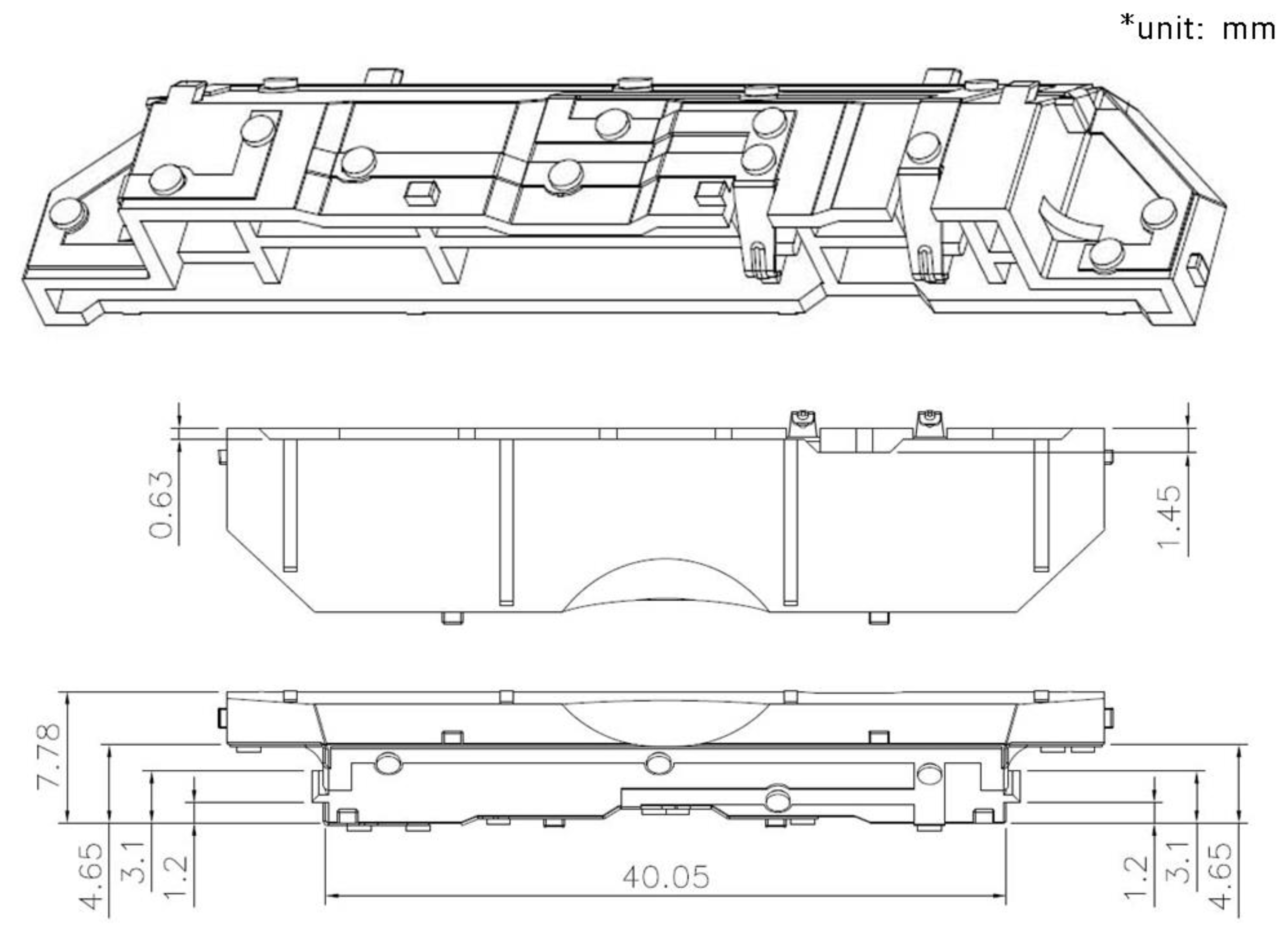
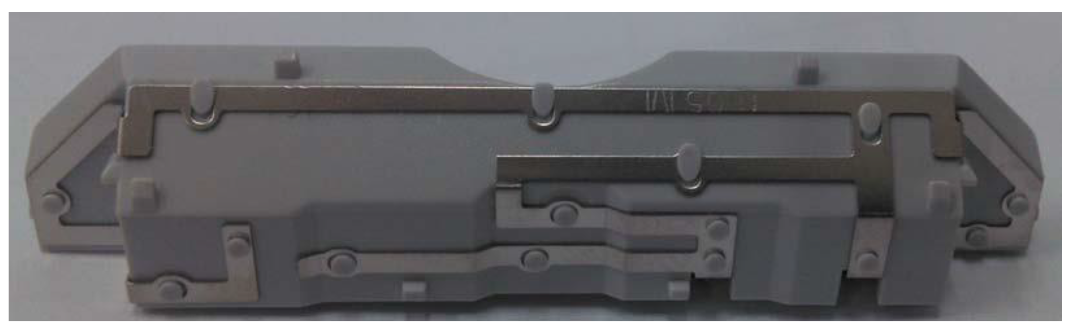
12]. As Equation (1) shows, the frequency band for a broad band width is proportional to the thickness of the material and is inversely proportional to the dielectric permittivity. Moreover, Equation (2) shows that the directivity of the antenna decreases as the dielectric permittivity increases. In designing the multi-band internal antenna, as the thickness of the dielectric material increases, the broad band characteristic of the antenna is improved. However, this also makes the width of the microstrip line increase, which means that the unwanted radiation occurs from the feed. To solve this problem, this paper suggests the structure of the multi-band internal antenna, as shown in
Figure 1, and the designed multi-band internal antenna is shown in
Figure 2.
3. Planar Inverted-F Antenna
In this paper, the multi-band internal antenna for WCDMA800, WCDMA850, GSM900, DCS, PCS, WCDMA2100, LTE2100 mobile communication services, and 5G communication networks is modeled, and the antenna characteristics are simulated with the coordinate system. This antenna is a flat antenna with a smaller area of rectangular patch plate on top of the ground surface of the plate, consisting of a ground surface, patch, feeder, short-circuit pin (or short-circuit strip). PIFA acts as a radiation element as the patch is resonated with the ground surface by current electric charge. Moreover, the height, width, length and position of the short-circuit wires determine bandwidth, gain and resonant frequency. PIFA can be built into a mobile phone because it does not have any protrusions, and two antennas can be attached to either side of the mobile phone or overlaid for dual mode of two frequency bands to improve its orientation. To improve the narrowband problem of existing PIFA, this paper suggests a modified PIFA form that positions the short-circuit between the radiant element and the ground surface. It also has the radiation patch to have wider bandwidth. The desired bandwidth (5.2%) was obtained with the minimum height of the antenna (h = 0.015λ) for use as built-in to the handset in the proposed manner. To make the antenna slim, this paper investigated how the location (Zs), width (Ws), length (d), short strip height (h), and dielectric change (εr) affected the antenna. With these factors, this paper also compared the bands with the existing PIFA antenna and represented the proposed pattern as H and E plane.
4. Simulation
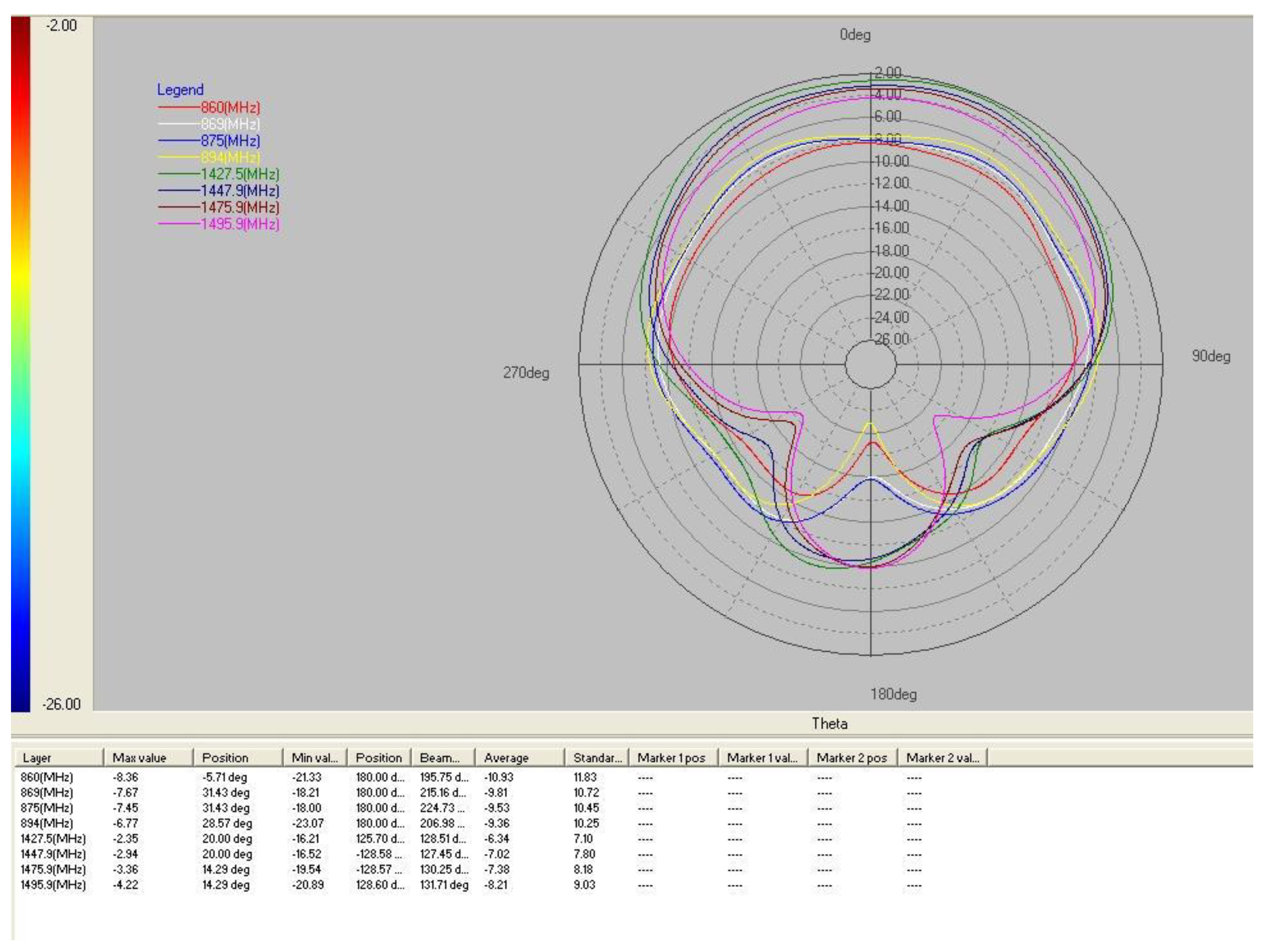
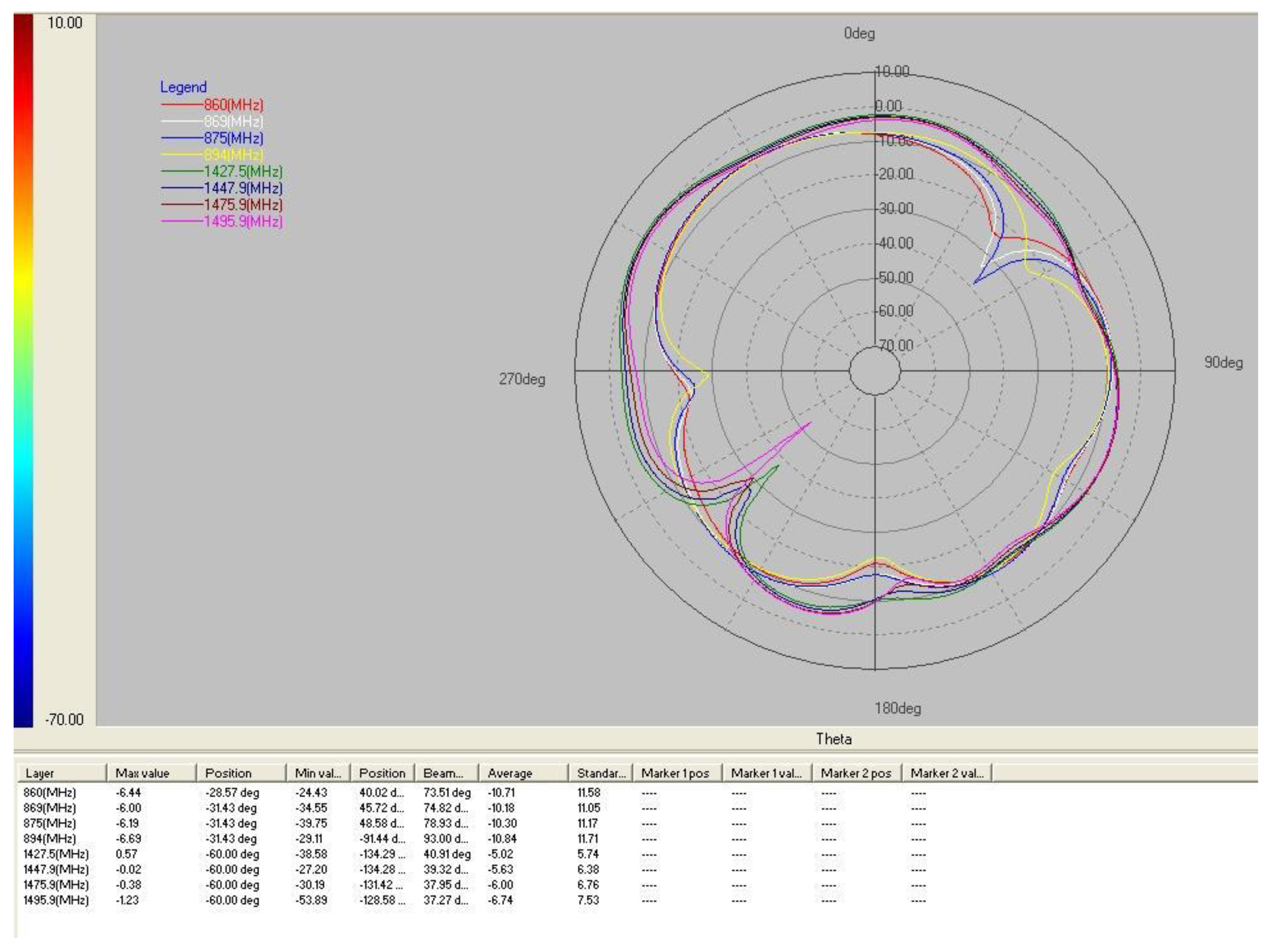
For the simulations, High Frequency Structure Simulator (HFSS) program ver. 11, which is based on the Finite Integration Method (FINM), is used to analyze the designed multi-band internal antenna for mobile communication. The radiation pattern of the multi-band internal antenna is simulated at H-plane, E1-plane, and E2-plane respectively, and the simulated radiation patterns are as shown in
Figure 3,
Figure 4 and
Figure 5.
As mentioned above, this paper suggests the multi-band internal antenna for WCDMA800, WCDMA850, GSM900, DCS, PCS, WCDMA2100, LTE2100 mobile communication services, and 5G communication networks.
Figure 4,
Figure 5 and
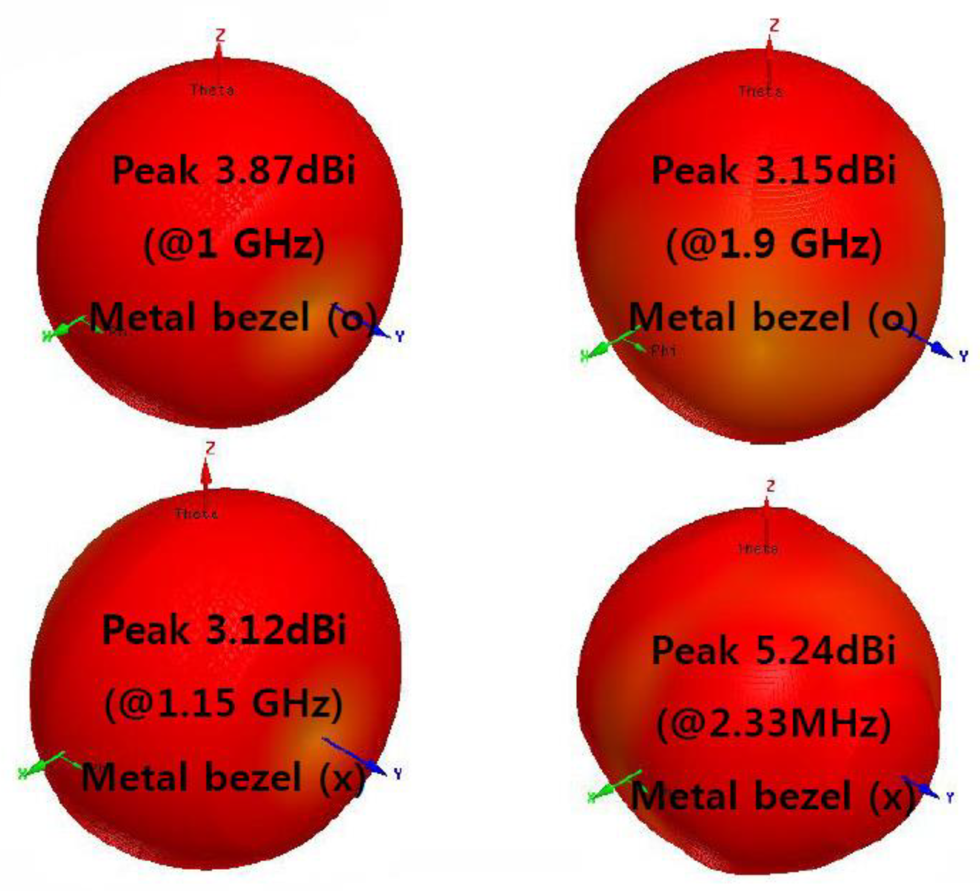
Figure 6 show the radiation pattern of the internal antenna at 824 MHz −2.17 GHz frequency band. To prove the antenna characteristics of the designed multi-band internal antenna in numerical value,
Table 1 and
Table 2 show the voltage standing wave ratio (VSWR) and the peak gain of the antenna at each frequency band, and the radiation pattern of the antenna is almost omni-directional, as shown in
Figure 3,
Figure 4 and
Figure 5. In the simulation of the radiation pattern, the impedance bandwidth is set from 824 MHz to 2.17 GHz, and the insertion loss is the minimum at 960 MHz. Although the simulated radiation patterns at H-plane and E-plane are not symmetric patterns, they show forward and backward patterns. Moreover, the radiation patterns are the maximum at the perpendicular direction to the antenna side.
5. Measurement
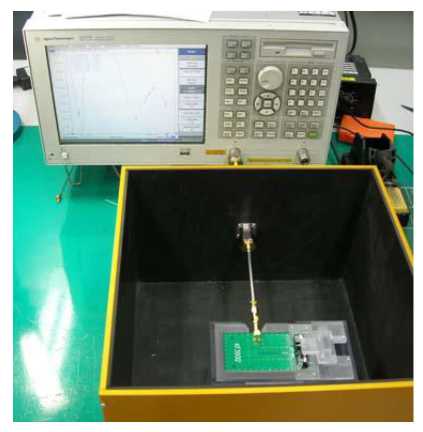
The simulated multi-band internal antenna is fabricated, and the VSWR and gain of the internal antenna were measured as shown in
Figure 6. For the measurement system, a network analyzer (Agilent 5071B), a calibration kit (Agilent 85033E), an adaptor (SMA Female ↔ SMA Male), and a measurement cable (SMS-SF141) are used. The method and procedure of the measurement are as follows. The shielded box is set to the port of the network analyzer, and the calibration for them is done. After setting the fabricated antenna to the set JIG and unit JIG, the set JIG is connected vertically to the port inside the shielded box and the unit JIG is connected horizontally to the port inside the shielded box, respectively. With the calibration of the network analyzer, the coaxial cable from the set JIG and unit JIG are connected to the port inside the shielded box. In the whole measurement procedure, the measurement should be performed on the non-conductive table. As shown in
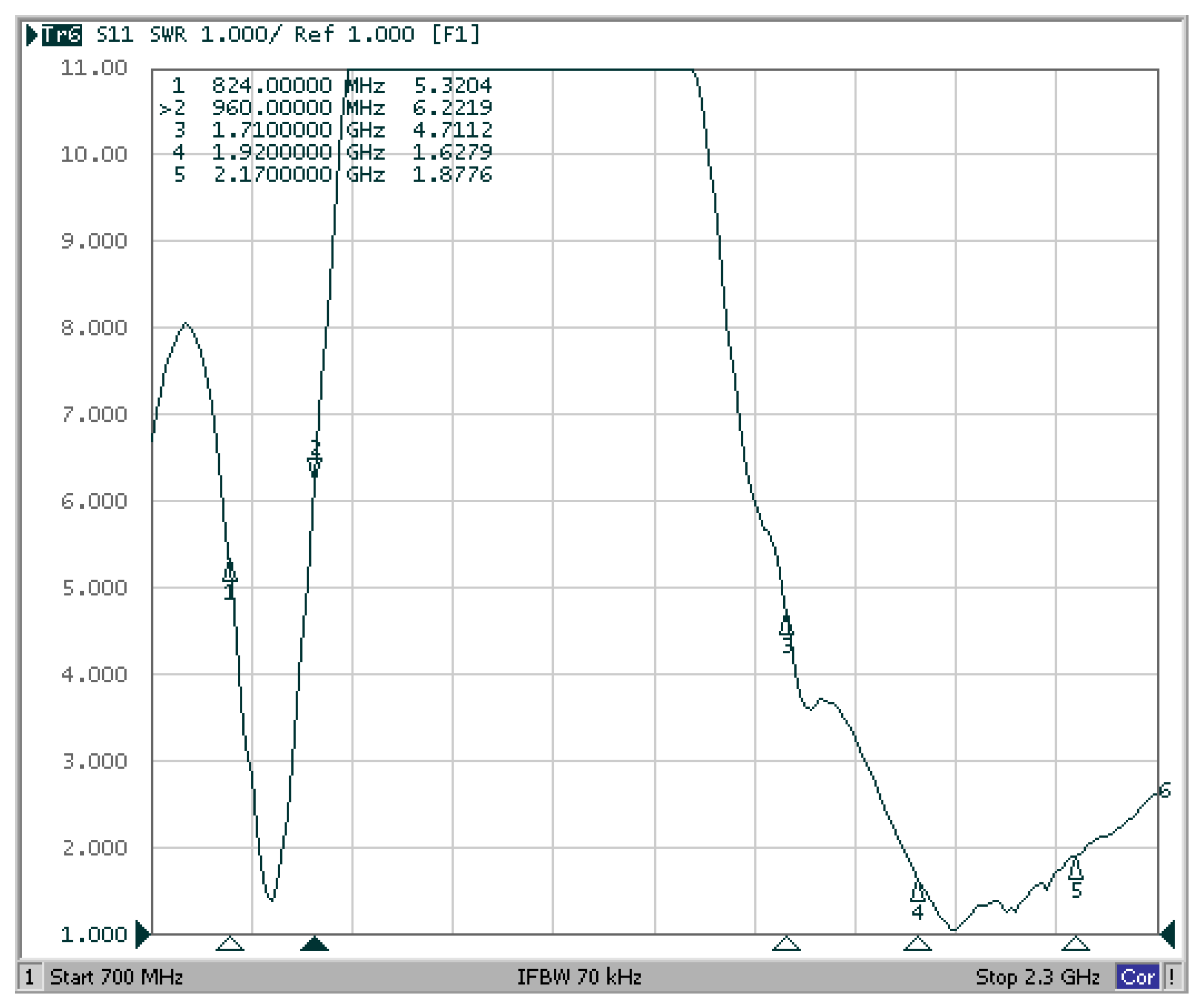
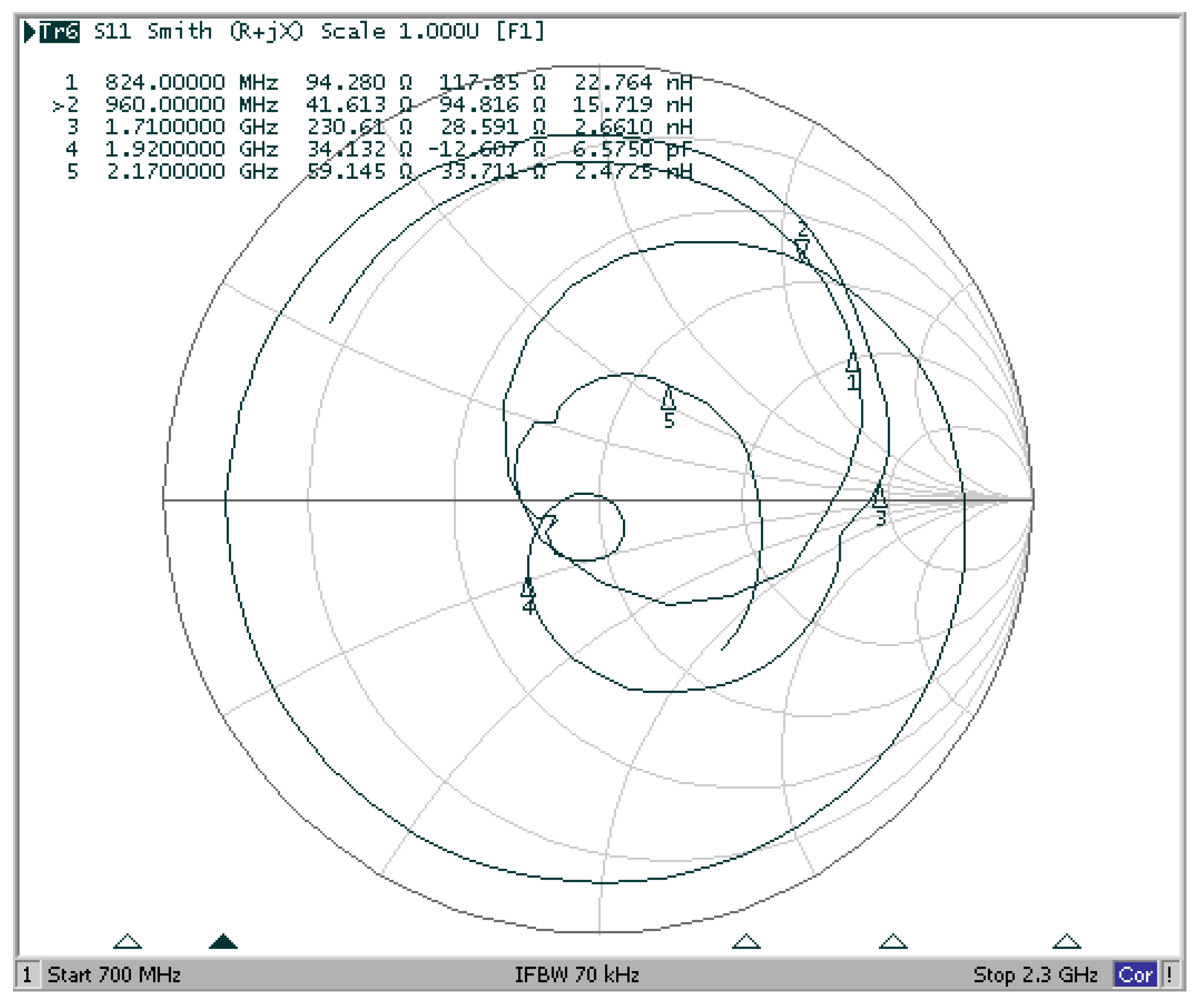
Figure 7 and
Figure 8, the measured VSWR satisfies the common use specification for the WCDMA800, WCDMA850, GSM900, DCS, PCS, WCDMA2100, LTE2100 mobile communication services, and 5G communication networks [
13,
14,
15].
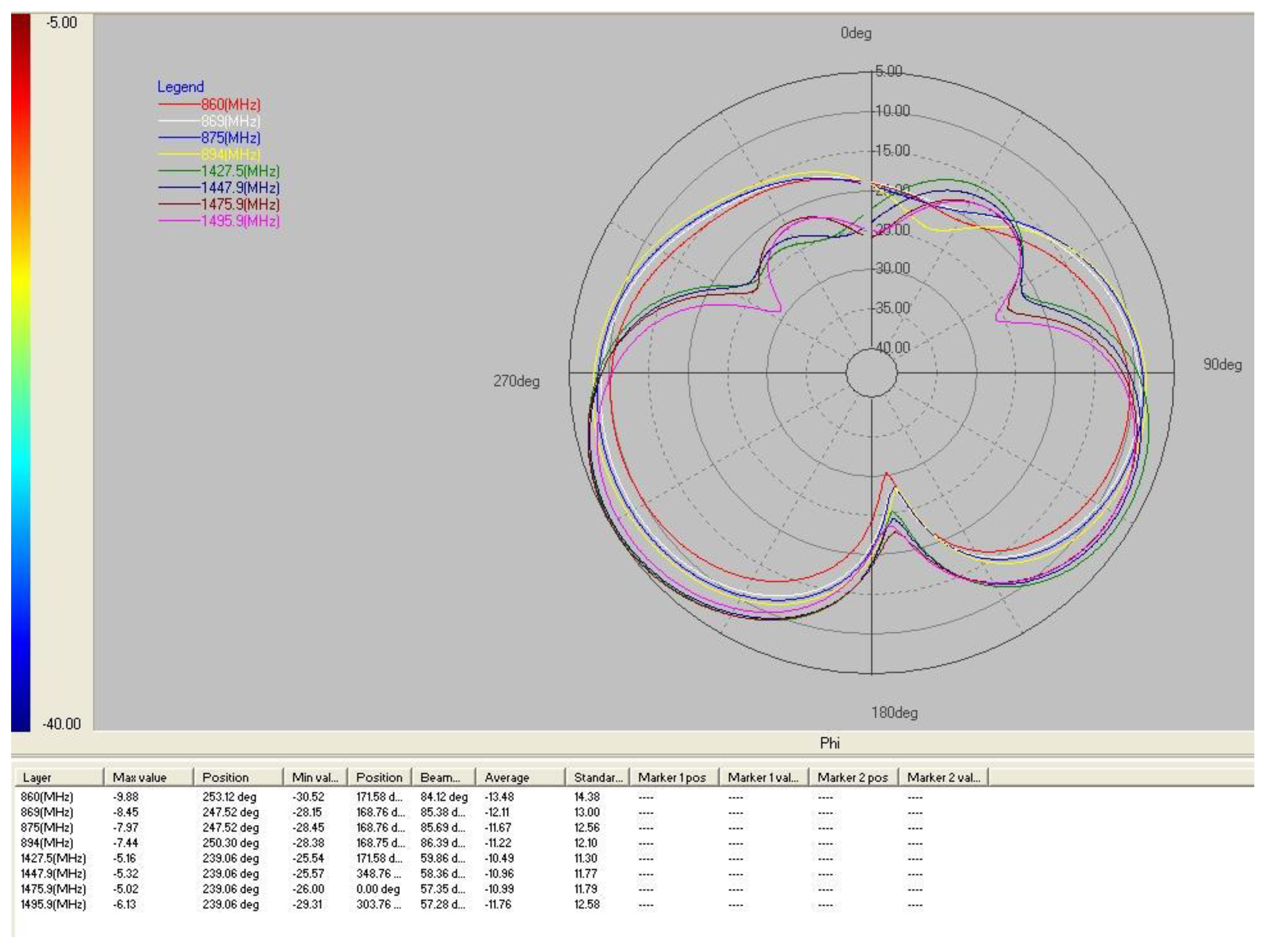
Figure 9 and
Table 3 show the measured radiation pattern and gain of the antenna respectively.
6. Conclusions
A compact multi-band internal antenna for mobile handsets which can cover WCDMA800, WCDMA850, GSM900, DCS, PCS, WCDMA2100, LTE2100 communication services, 5G communication networks is modeled, simulated, and measured in this paper. This multi-band internal antenna shows a satisfactory performance for a common application. The demonstration compared with the actual results of the antenna produced confirmed the possibility of commercializing the PIFA in the proposed way. The beam width at E-plane radiation pattern is about 120°, and the gain is 5.6 dBi at 960 MHz. The radiation patterns at E-plane from 824 MHz to 2.17 GHz have similar patterns, and a side lobe is formed at H-plane as the frequency increases. However, this side lobe is considered not to be a big problem because it is comparatively very small to the main beam which is vertical to the antenna side. Therefore, the designed multi-band internal antenna in this paper can satisfy the broadband characteristics in the view of an impedance, radiation pattern, and gain.


