Research on Ride Comfort and Driving Safety under Hybrid Damping Extension Control for Suspension Systems


1
School of Automobile and Traffic Engineering, Jiangsu University, Zhenjiang 212000, China
2
Automotive Engineering Research Institute, Jiangsu University, Zhenjiang 212000, China
*
Author to whom correspondence should be addressed.
Appl. Sci. 2020, 10(4), 1442; https://doi.org/10.3390/app10041442
Submission received: 9 January 2020
/
Revised: 26 January 2020
/
Accepted: 17 February 2020
/
Published: 20 February 2020
(This article belongs to the Collection Recent Applications of Active and Passive Noise Control)
Abstract
:This paper is concerned with the conflicting performances of ride comfort and driving safety for semi-active suspension systems. To alleviate this conflict, a novel hybrid damping extension control (HDEC) method is proposed. This method adopts various control methods and the weights of each method are determined by extension theory. Firstly, body acceleration and tire dynamic transformation are selected to evaluate ride comfort and driving safety performance for the semi-active suspension system and their frequency responses of passive suspension, sky-hook control, ground hook control, and S-GH (sky-ground hook) control are analyzed based on a two degree-of-freedom (2-DOF) model. Secondly, extension theory is introduced and the extension control system, which contains three modes and corresponding control algorithms, is established. In addition, the low-frequency excitation and high-frequency excitation simulations are designed to determine the parameters of the extension control system. Finally, ve-DYNA vehicle suspension model simulation is applied to prove the feasibility and effectiveness of the extension control. The simulation results show that, based on the suspension state, extension control can improve the performance of ride comfort and driving safety.
1. Introduction
The suspension system, playing a significant role in improving ride comfort and driving safety performance of in vehicles, is divided into the sprung mass part and the unsprung mass part [1]. A considerable number of studies about suspension control methods have been carried out to suppress the vibration of the sprung mass and the unsprung mass. For example, sky-hook/ground-hook control, sliding mode control, fuzzy control algorithm, etc. have been used for the suspension control system [2,3,4,5] to adapt to various conditions. Because of the simpler algorithm and better reliability, sky-hook control has been widely used in various vehicles. However, the ride comfort performance and the driving safety performance of the vehicle under sky-hook control is conflicting that the better ride comfort leads to the worse driving safety [6]. Therefore, in the light of vehicle state, intelligently restraining sprung mass and unsprung mass vibration at the same time is key to improving the comprehensive performance of the suspension system. Furthermore, the calibration process exerts a significant effect on suspension controller design. Based on the above analysis, instead of single control methods, hybrid control approaches with intelligent switching rules are suggested to improve the vehicle comprehensive performance. Among them, the sky-ground hook (S-GH) control [1] was used to enhance the performance of the controlled system.
In order to handle conflict requirements between the ride comfort and driving safety, the S-GH control method has been studied by various researchers for the semi-active suspension system. Goncalves et al. proposed this hybrid control method firstly, combining sky-hook control and ground-hook control [7]. Hongbin Ren et al. presented an adaptive sliding mode control algorithm based on the S-GH reference model [8]. Si-Zhong Chen et al. added a state observer to improve the accuracy of the state estimation for the S-GH suspension model [9]. Jing Zhao et al. proposed a hybrid system that consisted of acceleration driven damper control and ground-hook control and designed a fuzzy controller to decide the weight of each control [3]. D. H. Shi et al. proposed sky-ground hook control to suppress the vibration of energy-regenerative suspension and the mode switch strategy was decided by sliding mode controller [10]. Therefore, S-GH control is a good choice to alleviate the conflict problem between ride comfort and driving safety. However, S-GH control is essentially a compromise, not the desired solution.
Compared with single S-GH control, hybrid control combining with S-GH control may be a better solution. In other fields, the methods of the lookup table and rule base have been proposed to apply for the hybrid system. To make battery energy storage system more dispatchable, rule-based control scheme was proposed to incorporate the operating constraints of the battery energy storage system (BESS) by Sercan Teleke et al. [11] Xuefang Li et al. proposed the torque-leveling threshold-changing strategy, which involved a small number of rules than common rule-based control, to solve the energy management problem in parallel hybrid electric vehicles [12]. In terms of the angle measurement performance problem of a coprime linear array, Weike Zhang et al. adopted the direction-of-arrival estimation algorithm based on the lookup table method [13]. An alternative strategy for logarithmic transformation was presented by Xinyu Li et al. based on the lookup table to accelerate the imaging processing [14]. However, the design process of the lookup table and rule-based methods is time and effort consuming. In addition, the lookup table and rule-based methods are always switching systems, whose switching stability should be considered. Therefore, the novel theoretical guidance should be provided for the lookup table and rule-based methods to conduct the design process and eliminate the switching condition.
Fuzzy control has also been widely applied for a hybrid system recently. Do Xuan Phu et al. proposed an adaptive fuzzy PID controller based on the modified Riccati-like Equation to suppress the vibration for vehicle seat suspension [15]. Jingying Li et al. adopted a bio-inspired reference model based fuzzy adaptive tracking control which is applied for nonlinear suspension systems to isolate vibration [16]. To suppress the vibration of the Takagi-Sugeno fuzzy suspension models with input saturation, H. Ebrahimi Mollabashi et al. proposed a parallel distributed compensation-based composite nonlinear feedback control [17]. However, the establishment of the fuzzy rule base is still time and effort consuming under fuzzy control. Furthermore, these studies focus on reducing vibration of body acceleration, which improve ride comfort performance, rather than on improving the comprehensive performance between ride comfort and driving safety.
Therefore, numerous studies were shown that the extension theory had the potential to improve the comprehensive performance of the suspension system and eliminate the switching condition. Cheng-Biao Fu et al. applied the non-autonomous Chua’s circuit to preprocess the grid signal and analyzed preprocessed voltage signal based on the fractional Lorenz chaotic system and extension theory which was used to establish the classical and sectional domains according to the dynamic errors of fault conditions [18]. Da An et al. prioritized the alternative technologies for the treatment of urban sewage sludge and graded their sustainability performances based on extension theory [19]. Bo Yan et al. proposed the extension theory as a novel evaluation model for the agri-product supply chain competitiveness to amend the evaluation parameters under the current developments in society and economy [20]. Meng-Hui Wang et al. used an intelligent extension theory for human power generation system to reduce input saturation and high frequency switching in the sliding mode strategy, and increase efficiency and response speed [21]. Kuei-Hsiang Chao proposed a smart fault-tolerant control system based on the theory of Lorenz chaotic system and extension theory for locating faults and executing tolerant control in a three-level T-type inverter. The system executed fault diagnosis based on extension theory [22]. Under mixed road conditions with a large curvature range, an extendable preview switching control method for the lateral control of autonomous vehicles was proposed by Cai Ying Feng et al., which solved the problem of poor adaptability and low control accuracy of the lateral control system in autonomous driving vehicles [23]. However, there are few studies utilizing extension theory for the suspension system. Chen W.W. and Wang H.B. proposed extension control to improve vehicle suspension/steering integrated system performance [24]. To handle the optimal domain boundary problem, Hongbo Wang introduced the game theory to determine the domain of the extension control [25]. Notably, these studies have tended to focus on alleviating the conflicting problem between the suspension system and steering system, rather than on relieving the internal conflict for the suspension system.
Meanwhile, the research about road excitation and the 2-DOF suspension model were also developed. Leilei Zhao et al. created an identification method of road conditions based on vertical acceleration response and proposed a new 2-DOF semi-active suspension system based on the road statistical properties [26]. Wentao Xu et al. utilized an infinite Kirchhoff plate with the Kelvin foundation to establish the pavement system [27]. Zhenfeng Wang et al. presented the unscented Kalman filter to estimate the road profile by the vehicle states [28]. Hrovant firstly analyzed the relationship between sprung mass and unsprung mass based on the 2-DOF suspension model [29]. Analyzing the 2-DOF suspension model, Bustsuen found a kind of invariant point on the suspension system firstly [30]. Shun-Chang Chang et al. applied the method of codimension-two bifurcation analysis to analyze the 2-DOF semi-active suspension model [31]. Shida Nie added a tuned mass damper in a traditional 2-DOF suspension model to eliminate the unsprung adverse effect and applied the sliding mode controller to improve ride comfort across the whole frequency spectrum for in-wheel motor-driven vehicles [32].
Motivated by the above discussions, this paper proposes a kind of intelligent rule base method combining S-GH control based on the extension control. According to the driving state of the vehicle, the correlation degree of the semi-active suspension system is calculated by correlation function in the extension controller. According to the value of the correlation degree, the suspension control system is divided into three control regions: classical domain, extension domain, and non-domain. Based on the analysis of extension theory, in classical domain, the suspension system is controlled under traditional sky-hook control, in which the suspension system is stable while the sprung and unsprung vibration is small; in the extension domain, sprung vibration and unsprung vibration is larger, so the hybrid control strategy is used to prevent the unstable state for suspension system. In the non-domain, the vibration of sprung and the vibration of unsprung comprehensive performance exceed the control range of the controller. In order to restrain the unsprung vibration and ensure driving safety of the vehicle, ground-hook control should be adopted. Furthermore, the switching stability problem is avoided because of the application of a suitable correlation function. Finally, the validity of the hybrid extension control system is verified by MATLAB/Simulink and ve-DYNA software.
This paper is organized as follows. In Section 2, the 2-DOF suspension system and S-GH hybrid control are described in detail, and analyze the frequency response, comparing with sky-hook control and ground-hook control. Then, extension theory is introduced in Section 3 in detail to divide the area for the suspension system. Finally, in Section 4, hybrid damping extension control for the suspension system is simulated, and then the simulation is used to prove its feasibility.
2. Suspension System Model
In this section, the 2-DOF suspension model is introduced to describe the vertical vibration and the schematic diagram of the vehicle dynamics model is shown in Figure 1. It is assumed that tire damper is ignored. The stiffness of the tire is represented as constant Kt. m2 and m1 denote the sprung mass and the unsprung mass respectively. Suspension control force is denoted u. z1, z2, and q represent tire vertical displacement, sprung displacement and road excitation respectively [33]. ECU represents electronic control unit which handles the sensors signals to achieve control signals. The positive direction is shown in Figure 1.
Base on Newton’s second law, the equation of the 2-DOF controllable suspension model which is illustrated in Figure 1 is expressed as Equation (1)
where and refer to the acceleration of sprung mass and unsprung mass respectively.
3. Hybrid Damping Control
Because the spring-damper parallel connection structure connects between the sprung mass and unsprung mass, the desired hybrid control force is expressed as Equation (2)
where represents the spring force, K is the spring stiffness, and represent the sprung mass velocity and the unsprung mass velocity. The damping force is represented as , where Cgro is the desired ground-hook damping coefficient. Csky is the desired sky-hook damping coefficient. k(S) is the weight of the hybrid damping coefficient.
As illustrated in Figure 2, based on the Equations (1) and (2), the equations of hybrid control suspension system which is illustrated in Figure 2 are represented as
However, it is difficult to realize the desired sky-hook control and the desired ground-hook control in reality. Therefore, the equivalent damping coefficient is adopted to realize hybrid control. The equivalent damping coefficients are written as
Ceqs and Ceqg correspond separately to equivalent sky-hook damping coefficient and ground-hook damping coefficient. The equations of hybrid control suspension systems, in reality, are represented as
After Laplace transformation for Equation (3), the frequency response of the hybrid control suspension system can be expressed as
Based on the Equation (7), Equations (8)–(12) are defined as
The amplitude-frequency characteristic of , f and Fd can be inferred to
The parameters of the suspension system are shown in Table 1. The frequency responses of ride comfort and driving safety are illustrated in Figure 3 from the MATLAB/Simulink simulation when the vehicle drives over the C grade pavement at 40 m/s under the coefficient k(S) = −0.33.
Figure 3a describes that the body acceleration gain under the hybrid control is less than that under passive suspension. The frequency response of suspension dynamic displacement is illustrated in Figure 3b. The performance of hybrid control is better than the sky-hook control under high vibration (5–12 Hz), although hybrid control is still at a disadvantage to the passive suspension. Meanwhile, the ground-hook control performs best of all under high frequency (5–12 Hz), worst under low frequency (0–5 Hz). Figure 3c illustrates that the tire dynamic deformation gain of hybrid control is slightly higher than passive suspension under high frequency (5–12 Hz). However, compared with the sky-hook control, it has a significant decrease. The ground-hook control is superior to other control methods under high frequency (5–12 Hz). In low frequency (0–5 Hz), its gain is much higher than other control. Therefore, hybrid control can affect the amplitude-frequency of the suspension system. However, considering the vehicle state and road excitation, the weights of the hybrid system should be determined adaptively. Therefore, to cope with the problem, the extension control system is established.
4. Hybrid Control Based on Extension Theory
4.1. Extension Theory
Extension theory and extension control are used to solve contradiction problems. Extension theory primarily describes transformation characteristics of matter elements. Extension control provides a mathematical method to make extension theory in reality [35]. Base on extension theory and extension control, the traditional method range can be extended. For example, the fuzzy set range is extended from (0, 1) to (−∞, ∞) based on extension theory and extension control. Figure 4 shows the transformation from a fuzzy set to an extension set.
4.1.1. Matter-Element Theory
Matter-element theory reflects matter properties [36]. The 2-DOF suspension system is analyzed based on ride comfort indexes and driving safety indexes. Differences performance in suspension system is conveyed according to body acceleration and tire dynamic deformation, more specifically by a matrix (16).
where ϕi is the basic element. Oi is the matter-element, ε is the matter-element characteristics and µ is the value of the characteristic.
Because ride comfort and driving safety of the suspension system is not a single item, the vectors of characteristics are expressed as n-dimension matter-element. Equation (16) can be rewritten as
where εi is the characteristic of On, and <μi, ξi> is the characteristic value of εi.
4.1.2. Extension Sets
In order to extend a specific set into a continuous value range (−∞, ∞) and calculate the correlation degree, the extensive set is established [37]. The extensive set E(T) is required which are defined as
where y is the correlation function, y′ is extension function, T is the extension transformation based on the control strategies for extension set E(T), I is the real number field.
Extension set E(T) is composed of several parts as
where dA+, dA−, A+, A−, and J0(T) are positive extension domain, negative extension domain, positive classical domain, negative classical domain, and zero boundary of extension set respectively, which are shown as
Figure 5 illustrates the relationship between correlation function, extension function and extension set. The value of the correlation function determines the control field of the suspension system and extension function decides the trend of the control field. If extension function T(x) < 0, the system will tend to non-domain; If extension function T(x) > 0, the system will tend to the classical domain.
4.1.3. Correlation Function Construction
The correlation function is expressed as
where φ(x,A) and D(a,A,A0) are explained as
where A is assumed a domain and A0 is the other domain beside A.
4.2. Structure of the Extension Control System
The extension control system consists of upper and lower controllers, as depicted in Figure 6. The signal e, which is the deviation between output signal y and desired signal r, is taken as the input of the controller. The damping coefficient u, which meets the performance requirements of the suspension and the driving requirements of the vehicle, is calculated by the suspension extension switching controller. Therefore, the suspension with the extension control system forms a closed-loop control system.
The upper part is an extension controller, which divides the control area and decides the control strategy for the lower controller. In addition, control weight α of the lower controller is also calculated in the upper part. According to the change of control weight α, control methods are changed to expand the control range of the suspension control system. The lower controller is a damping controller. Through the control weight α calculated by the upper part, the control damping force is obtained. There are three control modes in the lower controller, which correspond to separately sky-hook control, ground-hook control, and hybrid control, as shown in Figure 7.
4.3. Upper Extension Controller Design
The upper part extension controller is composed of four parts: feature extraction, correlation degree calculation, measure mode division, and control reasoning mechanism [38].
4.3.1. Feature Extraction
The selection of feature parameters is related to control targets. The body acceleration and the tire dynamic deformation Fd reflect ride comfort and driving safety of suspension system respectively. Therefore, deviation of body acceleration and tire dynamic deformation e1 and e2 are both selected as the characteristics of the extension controller, which is shown as
Based on the repeatedly adjusted simulation, when the vehicle suspension system adopts sky-hook control, the permitted range of ride comfort is e10lim, the permitted range of driving safety is e20lim. While vehicle suspension adopts hybrid control, e11lim represents the permitted range of ride comfort, and the permitted range of driving safety is e21lim, as shown in Table 2. Meanwhile, the deviation e1 and e2 are selected as the characteristic vector S (ex, ey), the domain U of extensive set equals S.
4.3.2. Correlation Degree Calculation
The characteristic plane e1Oe2 of extension set E(T) describes the state of the suspension system. The origin of characteristic plane O (0, 0) is supposed as the expected state of the suspension system, which desired body acceleration value and desired tire dynamic deformation value is 0.
As illustrated in Figure 8, two-norm operator |OS| depicts the proximity to the expected state point as
where k1 and k2 are the influence factors. When k1 < k2, the extension set is more sensitive to the change of tire dynamic deformation. When k1 > k2, the extension set is more sensitive to the change of body acceleration.
Where the classical domain boundary is A0, the extensive domain boundary is A1. A0 and A1 are expressed as
The correlation degree of the extensive set is calculated by the correlation function k(S), which represents the effect on ride comfort and driving safety performance. Different modes are divided based on correlation degree, corresponding to different parts of the extension set.
4.3.3. Measure Mode Division and Control Reasoning Mechanism
Different parts of the extension set correspond to different states of vehicles. Three kinds of the domain in the extension set are divided to apply different control strategies.
- (1)
- Classical domain: When correlation degree satisfies the set M1 = {S|k(S) > 0}, it represents S is in the positive classical domain. The system is stable under this control strategy. However, the single control strategy might deteriorate the performance of the suspension system under specific conditions. Therefore, the value of extension function T(S) should be lower than 0. The new classical set is transformed as
- (2)
- Extension domain: When correlation degree satisfies M2 = {S|−1 < k(S) < 0}, which indicates that vector S is in the positive extension domain, where comprehensive performance of suspension system should be regarded. According to hybrid control, the vector S can be transformed from the extension domain to the classical domain, the transformation T(S) should be greater than 0. The new extension set is transformed as
- (3)
- Non-domain: When the correlation degree satisfies the condition of M3 = {S|K(S) < −1}, the vector S is in the non-domain, where the state is beyond the control range of the lower controller, thus the security is guaranteed first.
Different control strategies play different roles under different domains. Under the contradiction condition, in order to satisfy the comprehensive performance and eliminate the switching condition from the hybrid system, the extension control will decide suitable methods and make a transition by correlation function. The relationship between correlation function and extension function for the suspension system based on extension theory is illustrated as Figure 9:
Based on the production rule, the control reasoning mechanism of the extensive controller is described as follows:
IF k(S) ∈ M1; then sky-hook control
IF k(S) ∈ M2; then hybrid control
IF k(S) ∈ M3; then ground-hook control
4.4. Lower Extension Controller Design
The lower extension controller consists of three parts: sky-hook control, hybrid control, and ground-hook control.
4.4.1. Sky-Hook Control
When S is in the classical domain, it means that the road excitation is faint, and the main index is the body acceleration. Therefore, the sky-hook control is used in M1.
As illustrated in Figure 10, because the sprung mass is connected with a damper, the desired sky-hook controller Equation (36) is described as
Bring the Equation (36) into the Equation (1)
4.4.2. Hybrid Damping Control
M2 is the main part of the upper extension controller. When the state of the suspension system is in the extension domain, the suspension system will be in an unstable state under the sky-hook control. Therefore, instead of sky-hook control, hybrid control is adopted to keep the suspension system stable.
When S is in the extension domain under the decision of the upper controller, the control reasoning mechanism reflects that hybrid control is used. While considering ride comfort and driving safety, the control strategy selects the damping coefficient to adjust the vehicle state. Therefore, k(S) represents the weight of the hybrid control. The range of k(S) is [−1, 0]. When k(S) is 0, it is the sky-hook control; when k(S) is −1, it is the ground-hook control; when k(S) is the value between −1 and 0, it becomes hybrid control.
4.4.3. Ground-Hook Control
M3 illustrates that the working model of the suspension system is in non-domain. Ground-hook control is applied to improve the safety of the vehicle.
As illustrated in Figure 11, because the unsprung mass is connected with a damper, the ground-hook control force is expressed as Equation (38)
Because the ground-hook control suspension system which is a kind of semi-active suspension is applied to Equation (1), the equation of the ground-hook control suspension system is expressed as Equation (39), based on Equation (1) and Equation (38)
In summary, the control input of the extension control system is
In order to make the process of the proposed hybrid damping extension control clearly, the extension control is illustrated as the flow chart, shown in Figure 12.
5. Simulation
5.1. Parameter of the Extension Controller
In order to determine the parameters of the extension controller, the extension controller is simulated, compared with passive suspension and the sky-hook control. Because the extension controller is a nonlinear time-varying system, the time-domain analysis is applied to the extension controller [42]. The amplitude responses of each control method are obtained by MATLAB/Simulink under sinusoidal excitation. The parameters of the vehicle model depend on the data in Table 1. The parameters of the extension controller are determined in Table 2 based on the low-frequency signal and high-frequency signal simulation. When the parameters of the extension controller are determined as Table 2, the suspension system could obtain good control performances.
The Simulink model of hybrid damping extension control for the suspension system is illustrated in Figure 13.
The control targets are and Fd, which are sensitive to the low-frequency excitation and the high-frequency excitation respectively. Therefore, low-frequency excitation (frequency 1 Hz, amplitude 0.02 m) and high-frequency excitation (frequency 11.1 Hz, amplitude 0.02 m) are used as inputs of the Simulink model respectively. The time responses of body acceleration, suspension dynamic deflection, and tire dynamic deformation are compared under passive suspension, sky-hook control and extension control. The simulation time is set to 20 s, as shown in Figure 14.
As shown in Figure 14, all indexes of the sky-hook control and the extension control are better than that of the passive suspension under low-frequency excitation.
Compared with the sky-hook control, the amplitude of body acceleration, suspension dynamic displacement, and tire dynamic deformation of the extension control is similar, that the difference is not significant.
Table 3 describes the RMS of each index under different control methods quantitatively. The RMS of the body acceleration under extension control increases 6% from that under the sky-hook control. The responses of suspension dynamic displacement and the tire dynamic deformation decrease 0.5% and 9%, respectively. It means that compared with the sky-hook control, the ride comfort performance of extension control reduces slightly, while the drive safety performance is improved. However, compared with the passive suspension, body acceleration under extension control decreases by 55%. The value of suspension dynamic displacement increases 12.3% and the tire dynamic deformation decreases 57%, respectively. It reflects compared with the passive suspension under low-frequency excitation, the performance of the ride comfort can be significantly improved by extension control.
Figure 15 illustrates the weight α change of the extension controller under low frequency. The working range of α is above 0.8. It shows that the weight of the upper controller under low frequency makes the lower controller similar to sky-hook control, which improves ride comfort and driving safety performance.
With sky-hook control and extension control, the RMS value of body acceleration, tire dynamic deformation and suspension dynamic displacement under high frequency are significantly higher than the passive suspension. However, compared with sky-hook control, extension control has a significant decrease in ride comfort and driving safety performance, as shown in Figure 16.
Table 4 reflects the RMS of ride comfort and driving safety indexes under high frequency. The acceleration body under extension control is increased 3.1% from the passive suspension, while the suspension dynamic displacement and the tire dynamic deformation under the extension control deteriorate by 76.7% and 61%, respectively. However, compared with sky-hook control, the body acceleration under extension control reduces 6.4%, and the suspension dynamic displacement and tire dynamic deformation reduce 71% and 65% respectively, indicating that extension control can suppress high-frequency vibration better than sky-hook control.
Figure 17 reflects the weight α change in the extension control system under high-frequency excitation. The working range of weight α varies from 0 to 0.25. It shows that the weight of the upper controller under low frequency will make the lower controller similar to ground-hook control, which improves the driving safety performance.
5.2. Simulation-Based on ve-DYNA Software under Random Road Excitation
In order to make the extension control system apply for the actual complicated suspension system, the suspension system based on ve-DYNA software is adopted to simulation. ve-DYNA is a high precision vehicle dynamics simulation software, which has been applied to solve various engineering problems in practice. In addition, it is more significant to study the response of vehicles under random road excitation, which is the main input in the suspension system. Therefore, the simulation-based on ve-DYNA software under random road excitation is proposed to validate the feasibility and effectiveness of the extension control.
As illustrated in Figure 18, the ve-DYNA suspension model is adopted to test the performance of various control methods. In order to compare the performance of the above three methods, passive suspension, sky-hook control system, and the extension control system are applied in the ve-DYNA suspension model. Based on the driving states, these methods change the damper force to affect the performance of ride comfort and driving safety for the ve-DYNA suspension model adaptively. The outputs of the suspension model are body acceleration, suspension dynamic displacement, and tire dynamic deformation, which are represented the indexes of ride comfort and driving safety. In addition, when one of the methods is adopted, other methods in ve-DYNA are disconnected.
Assuming that vehicle is straightly driving on D-grade road at 60 km/h speed while adopting the passive suspension, sky-hook control, and extension control respectively. Therefore, the suspension model of bmw_325i_88 is applied and the work condition is set as go_initial_speed under 60 km/h, which is illustrated in Figure 19. In addition, the grade D road is selected as the road excitation.
As illustrated in Figure 20, the weights of extension control are calculated and are presented. Because the ve-DYNA suspension model is the vehicle dynamical model, there are four extension control weights, which denote the four corners of the vehicle. The reaction time that the time interval for the weight change is 0.2 s.
The simulation time is 20 s. The results that the responses of ride comfort and driving safety are compared under the passive suspension, sky-hook control, and extension control are shown as Figure 21, Figure 22, Figure 23, Figure 24 and Figure 25.
Figure 21a shows that compared with the passive suspension, sky-hook control and extension control have smaller body acceleration in the time-domain, which denotes that the ve-DYNA suspension system under sky-hook control and extension control has better ride comfort. In order to exhibit the amplitude-frequency response of ride comfort, the time domain chart is transformed as the frequency domain chart by Fourier transformation. As Figure 21b illustrated, compared with passive suspension, the performance of ride comfort under sky-hook control and extension control is mainly improved around low frequencies (0–5 Hz). In addition, extension control performs better than sky-hook control in high frequencies. Therefore, extension control not only guarantees the ride comfort performance but also suppresses high-frequency vibration compared with sky-hook control.
As illustrated in Figure 22 and Figure 23, because the ve-DYNA model is a vehicle dynamic model, there are four kinds of suspension dynamic displacement. Figure 22 shows that the suspension dynamic displacement of front overhang under sky-hook control and extension control is better than that of passive suspension, while the performance of rear overhang is not obvious, we suggest the transferring of axle’s load may lead to this phenomenon which makes the front overhang and rear overhang is a different system. Similarly, after Fourier transformation, Figure 23 shows the frequency domain performance of suspension dynamic displacement. As illustrated in Figure 23, the performance of sky-hook control and extension control is similar. Compared with passive control, sky-hook control and extension control are worse than passive suspension in 0–0.8 Hz frequency band, while sky-hook control and extension control are better than passive suspension in 0.8–3 Hz frequency band. Therefore, further study should be carried out.
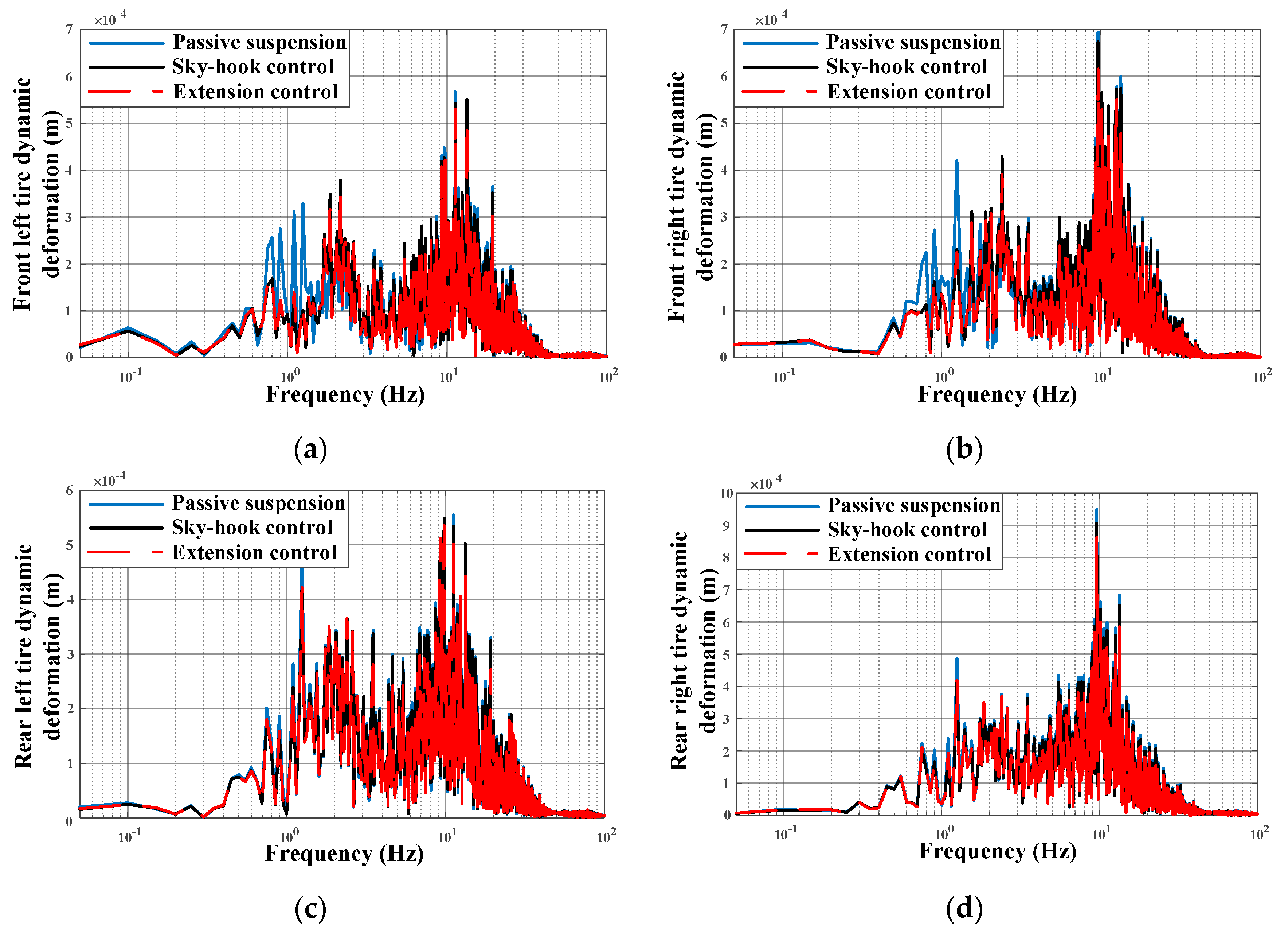
Figure 24 and Figure 25 show the tire dynamic deformation performance for the ve-DYNA model. In the time-domain graph, sky-hook control and extension control are better than passive control. However, the tire dynamic deformation performance under sky-hook control and extension control is closed. As shown in Figure 25, the tire dynamic deformation response at low range (0–5 Hz) with extension control is similar that of sky-hook control and better than passive, at high-frequency range (5–12 Hz), the extension control performs better than the passive control and sky-hook control. Therefore, extension control not only suppresses the tire dynamic deformation under random excitation, but also improves the performance of tire dynamic deformation at high frequency.
However, it is necessary to make a qualitative comparison among the passive suspension, sky-hook control and extension control. Furthermore, based on the closed data, it is obvious that some of the previous figures after ve-DYNA simulation are difficult to be distinguished. Therefore, the root mean square (RMS) of ride comfort and driving safety are represented as follows.
Table 5 shows the RMS of body acceleration, suspension dynamic displacement, and tire dynamic deformation in detail. Comparing the data in Table 5, it can be seen that body acceleration under passive suspension is higher 12.6% than that of extension control, while the extension control increases only 0.3% from the sky-hook control. The RMS of all kinds of suspension dynamic displacement is similar among all control methods. However, the RMS of tire dynamic deformation with extension control is better than sky-hook control, which decreases around 3–5% from sky-hook control. Therefore, based on the information from Table 5, extension control can adjust the performance of body acceleration and tire dynamic deformation.
6. Conclusions
In this paper, the weight of the sky-ground hook control method under various road excitation was studied based on the 2-DOF suspension model. Then, with the proposed extension controller, the effect of the 2-DOF suspension system on ride comfort indexes was studied.
The following main conclusions can be drawn:
- (1)
- Based on the 2-DOF suspension model, sky-hook, ground-hook, and S-GH control are established. The frequency responses have analyzed to study the influence of S-GH weight.
- (2)
- Based on the extension theory, the hybrid damping extension control is established under the simulation. The optimal weight of S-GH control is conducted by correlation function.
- (3)
- Compared to the sky-hook control algorithm and the passive suspension, the proposed hybrid damping extension control is simulated based on ve-DYNA vehicle simulation. Notably, the control effectiveness of the hybrid controller is highlighted under complicated conditions.
In the future, we will make a profound study for the extensive theory and try to use other hybrid control methods for active/semi-active suspension system, in order to improve comprehensive ride comfort performance.
Author Contributions
Conceptualization, G.G., Y.Y. and L.S.; Methodology, G.G., Y.Y. and H.L.; Software, Y.Y.; Formal analysis, G.G., Y.Y. and L.S.; Funding acquisition, G.G.; Investigation, G.G.; Project administration, G.G.; Resources, G.G. and Y.Y.; Validation, G.G., Y.Y. and L.S.; Methodology, G.G., Y.Y. and H.L.; Writing—original draft, Y.Y.; Writing—review and editing G.G., Y.Y., L.S. and H.L. All authors have read and agreed to the published version of the manuscript.
Funding
This work is financially supported by the National Natural Science Fund (nos. 51875256, 51675235, and 51575241).
Acknowledgments
We are grateful to the valuable comments by the anonymous reviewers, which have helped improve this manuscript.
Conflicts of Interest
The author(s) declared no potential conflicts of interest with respect to the research, authorship, and/or publication of this article.
References
- Editorial Department of China Journal of Highway and Transport. Review of China’s automotive engineering research progress: 2017. China J. Highw. Transp. 2017, 30, 1–197. [Google Scholar]
- Karnopp, D.; Crosby, M.; Harwood, R.A. Vibration control using semi-active force generators. ASEM J. Eng. Ind. 1974, 96, 619–626. [Google Scholar] [CrossRef]
- Zhao, J.; Wong, P.K.; Xie, Z.C. Design of a road-friendly SAS system for heavy-duty vehicles based on a fuzzy-hybrid-ADD and GH-control strategy. Shock Vib. 2016, 1–7. [Google Scholar] [CrossRef]
- Eltantawie, M.A. Decentralized neuro-fuzzy control for half a car with the the semi-active suspension system. Int. J. Automot. Technol. 2012, 13, 423–431. [Google Scholar] [CrossRef]
- Pusadkar, U.S.; Chaudhari, S.D.; Shendge, P.D. Linear disturbance observer-based sliding mode control for active suspension systems with the non-ideal actuator. J. Sound Vib. 2019, 442, 428–444. [Google Scholar] [CrossRef]
- Krauze, P.; Kasprzyk, J.; Kozyra, A. Experimental analysis of vibration control algorithms applied for an off-road vehicle with magnetorheological dampers. J. Low Freq. Noise Vib. Act. Control. 2018, 37, 619–639. [Google Scholar] [CrossRef] [Green Version]
- Goncalves, F.D.; Ahmadian, M.A. A hybrid control policy for semi-active vehicle suspension. Shock Vib. 2003, 10, 59–69. [Google Scholar] [CrossRef] [Green Version]
- Hongbin, R.; Yuzhuang, Z.; Si-Zhong, C. State observer-based adaptive sliding mode control for semi-active suspension systems. J. Vibroeng. 2015, 17, 1464–1475. [Google Scholar]
- Hongbin, R.; Si-Zhong, C.; Yuzhuang, Z. The observer-based hybrid control algorithm for semi-active suspension systems. J. Cent. South Univ. 2016, 23, 2268–2275. [Google Scholar]
- Shi, D.H.; Chen, L.; Wang, R.C. Research on energy-regenerative performance of suspension system with semi-active control. J. Vib. Eng. Technol. 2019, 7, 465–475. [Google Scholar] [CrossRef]
- Teleke, S.; Baran, M.E.; Bhattacharya, S.; Huang, A.Q. Rule-Based control of battery energy storage for dispatching intermittent renewable sources. IEEE Trans. Sustain. Energy 2010, 1, 117–124. [Google Scholar] [CrossRef]
- Li, X.F.; Evangelou, S.A. Torque-Leveling threshold-changing rule-based control for parallel hybrid electric vehicles. IEEE Trans. Veh. Technol. 2019, 68, 6509–6523. [Google Scholar] [CrossRef]
- Zhang, W.; Chen, X.; Cui, K.; Xie, T.; Yuan, N. DOA estimation for coprime linear array based on MI-ESPRIT and lookup table. Sensors 2018, 18, 3043. [Google Scholar] [CrossRef] [PubMed] [Green Version]
- Li, X.; Liang, S.; Zhang, J. Acceleration of OCT signal processing with lookup table method for logarithmic transformation. Appl. Sci. 2019, 9, 1278. [Google Scholar] [CrossRef] [Green Version]
- Phu, C. A new adaptive fuzzy PID controller based on Riccati-like equation with application to vibration control of vehicle seat suspension. Appl. Sci. 2019, 9, 4540. [Google Scholar] [CrossRef] [Green Version]
- Li, J.; Jing, X.; Li, Z.; Huang, X. Fuzzy adaptive control for nonlinear suspension systems based on a bioinspired reference model with deliberately designed nonlinear damping. IEEE Trans. Ind. Electron. 2019, 66, 8713–8723. [Google Scholar] [CrossRef]
- Ebrahimi Mollabashi, H.; Mazinan, A.H.; Hamidi, H. Takagi-Sugeno fuzzy-based CNF control approach considering a class of constrained nonlinear systems. IETE J. Res. 2018, 65, 872–886. [Google Scholar] [CrossRef]
- Chengbiao, F.; Anhong, T.; Yuchung, L. Fractional-Order chaos synchronization for real-time intelligent diagnosis of islanding in solar power grid systems. Energies 2018, 11, 1183. [Google Scholar] [CrossRef] [Green Version]
- Da, A.; Beidou, X.; Jingzheng, R. Multi-Criteria sustainability assessment of urban sludge treatment technologies: Method and case study. Resour. Conserv. Recycl. 2018, 128, 546–554. [Google Scholar]
- Bo, Y.; Zhuo, C.; Hongyuan, L. Evaluation of agriproduct supply chain competitiveness based on extension theory. Oper. Res. 2019, 19, 543–570. [Google Scholar]
- Menghui, W.; Herterng, Y.; Weijhe, J. Application of extension sliding mode strategy to maximum power point tracking in human power generation systems. Appl. Sci. 2015, 5, 259–274. [Google Scholar]
- Kueihsiang, C.; Longyi, C.; Fuqiang, X. Smart fault-tolerant control system based on chaos theory and extension theory for locating faults in a three-level T-type inverter. Appl. Sci. 2019, 9, 3071. [Google Scholar] [CrossRef] [Green Version]
- Yingfeng, C.; Yong, Z.; Xiaoqiang, S. Research on lateral extendable preview switching control system for autonomous vehicles. Automot. Eng. 2018, 40, 1032–1039. [Google Scholar]
- Chen, W.; Wang, H. Function allocation based vehicle suspension/steering system extension control and stability analysis. J. Mech. Eng. 2013, 49, 67–75. [Google Scholar] [CrossRef]
- Wang, H. Enhancing vehicle suspension system control performance based on the improved extension control. Adv. Mech. Eng. 2018, 10. [Google Scholar] [CrossRef]
- Leilei, Z.; Yuewei, Y.; Changcheng, Z. A hydraulic semi-active suspension based on road statistical properties and its road identification. Appl. Sci. 2018, 8, 740. [Google Scholar] [CrossRef] [Green Version]
- Xu, W.; Chen, Y.; Xiang, P. Vertical random vibration analysis of adjacent building induced by highway traffic load. Adv. Mech. Eng. 2016, 8. [Google Scholar] [CrossRef]
- Zhenfeng, W.; Yechen, Q.; Liang, G. Vehicle system state estimation based on adaptive unscented Kalman filtering combing with road classification. IEEE Access 2017, 5, 27786–27799. [Google Scholar]
- Hrovat, D. Influence of unsprung weight on vehicle ride quality. J. Sound Vib. 1988, 124, 497–516. [Google Scholar] [CrossRef]
- Butsuen, T. The Design of Semi-Active Suspensions for Automotive Vehicles. Ph.D. Thesis, Massachusetts Institute Technology, Boston, MA, USA, 1989. [Google Scholar]
- Chang, S.-C.; Hu, J.-F. Codimension-Two bifurcation analysis and chaos synchronization of a quarter-car vehicle model. Adv. Mech. Eng. 2018, 10. [Google Scholar] [CrossRef] [Green Version]
- Nie, S.; Zhuang, Y.; Chen, F. A method to eliminate the unsprung adverse effect of in-wheel motor-driven vehicles. J. Low Freq. Noise Vib. Act. Control. 2018, 37, 955–976. [Google Scholar] [CrossRef] [Green Version]
- Zhisheng, Y. Automobile Theory; China Machine Press: Beijing, China, 2006. [Google Scholar]
- Nugroho, P.W.; Li, W.H.; Du, H.P.; Alici, G. An adaptive neuro-fuzzy hybrid control strategy for a semi-active suspension with magnetorheological damper. Adv. Mech. Eng. 2014, 6. [Google Scholar] [CrossRef]
- Wang, M.H.; Tsai, H.H. Fuel cell fault forecasting system using grey and extension theories. IET Renew. Power Gener. 2012, 6, 373–380. [Google Scholar] [CrossRef]
- Li, C.; Zhang, W.-D.; Lan, Y.X. Early warning of risks of copyright infringement in the digital library based on extension theory. Electron. Libr. 2016, 34, 250–264. [Google Scholar] [CrossRef]
- Tian, A.H.; Fu, C.B.; Li, Y.C.; Yau, H.T. Intelligent ball bearing fault diagnosis using fractional Lorenz chaos extension detection. Sensors 2018, 18, 3069. [Google Scholar] [CrossRef] [Green Version]
- Hongbo, W.; Zhi, X.; Zhenguo, H. Research on multi-mode extension fuzzy switching control of EPS. J. Hefei Univ. Technol. 2018, 41, 1084–1092. [Google Scholar]
- Wen, C.; Chunyan, Y. Basic theory and methodology on extensions. Chin. Sci. Bull. 2013, 58, 1190–1199. [Google Scholar]
- Wang, T.C.; Yang, A.J.; Zhong, S.S. Multi-Attribute extension fuzzy optimized decision-making model of scheme design. Teh. Vjesn. Tech. Gaz. 2014, 21, 239–247. [Google Scholar]
- Li, Z.; Yu, W.; Cui, X. Online Classification of Road Roughness Conditions with Vehicle Unsprung Mass Acceleration by Sliding Time Window. Shock Vib. 2018, 1–13. [Google Scholar] [CrossRef]
- Strecker, Z.; Roupec, J.; Mazurek, I. Influence of response time of magnetorheological valve in Skyhook controlled three-parameter damping system. Adv. Mech. Eng. 2018, 10, 1–8. [Google Scholar] [CrossRef]
Figure 1.
2-DOF vehicle controllable suspension model.
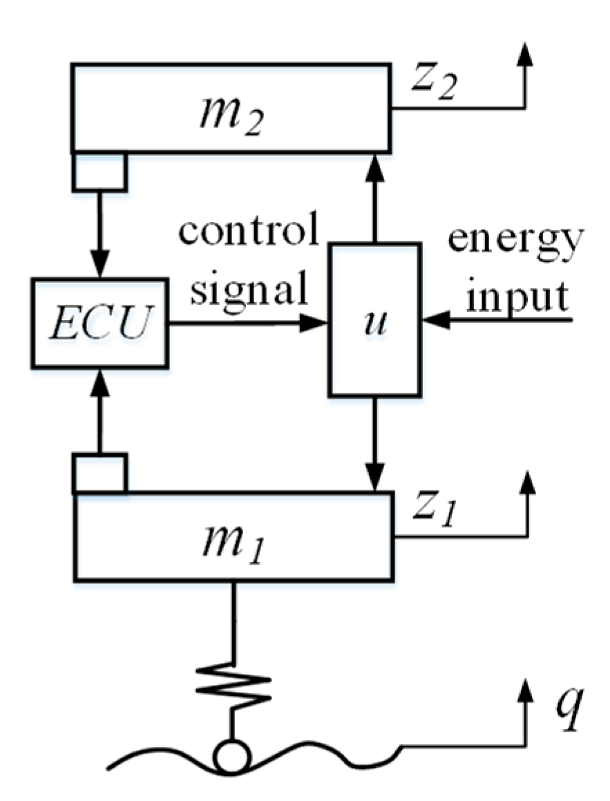
Figure 2.
Principle diagram of the hybrid damping control.
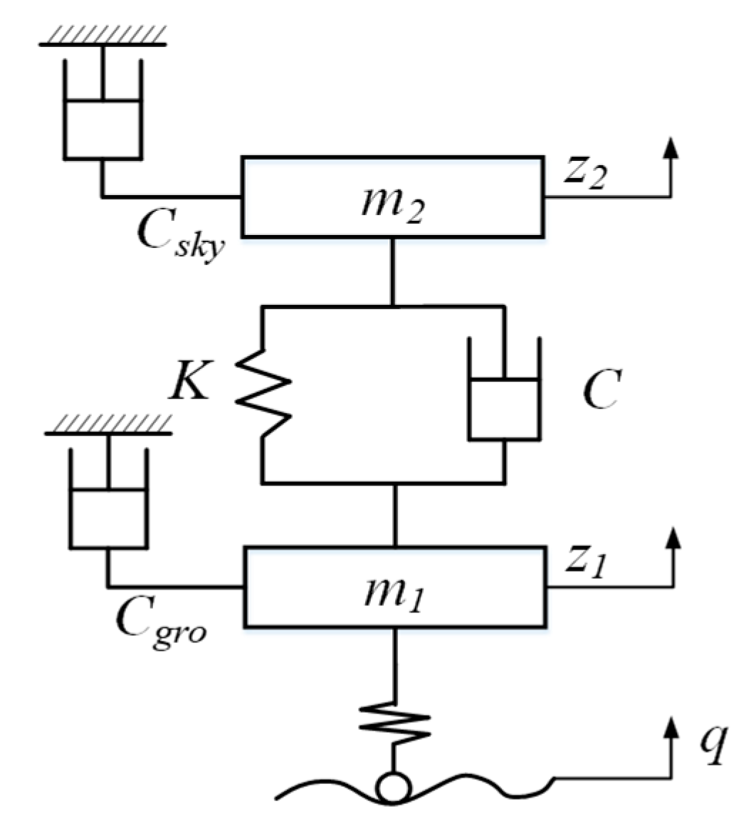
Figure 3.
Ride comfort and driving safety frequency responses: (a) Body acceleration; (b) Suspension dynamic displacement; (c) Tire dynamic deformation.
Figure 3.
Ride comfort and driving safety frequency responses: (a) Body acceleration; (b) Suspension dynamic displacement; (c) Tire dynamic deformation.
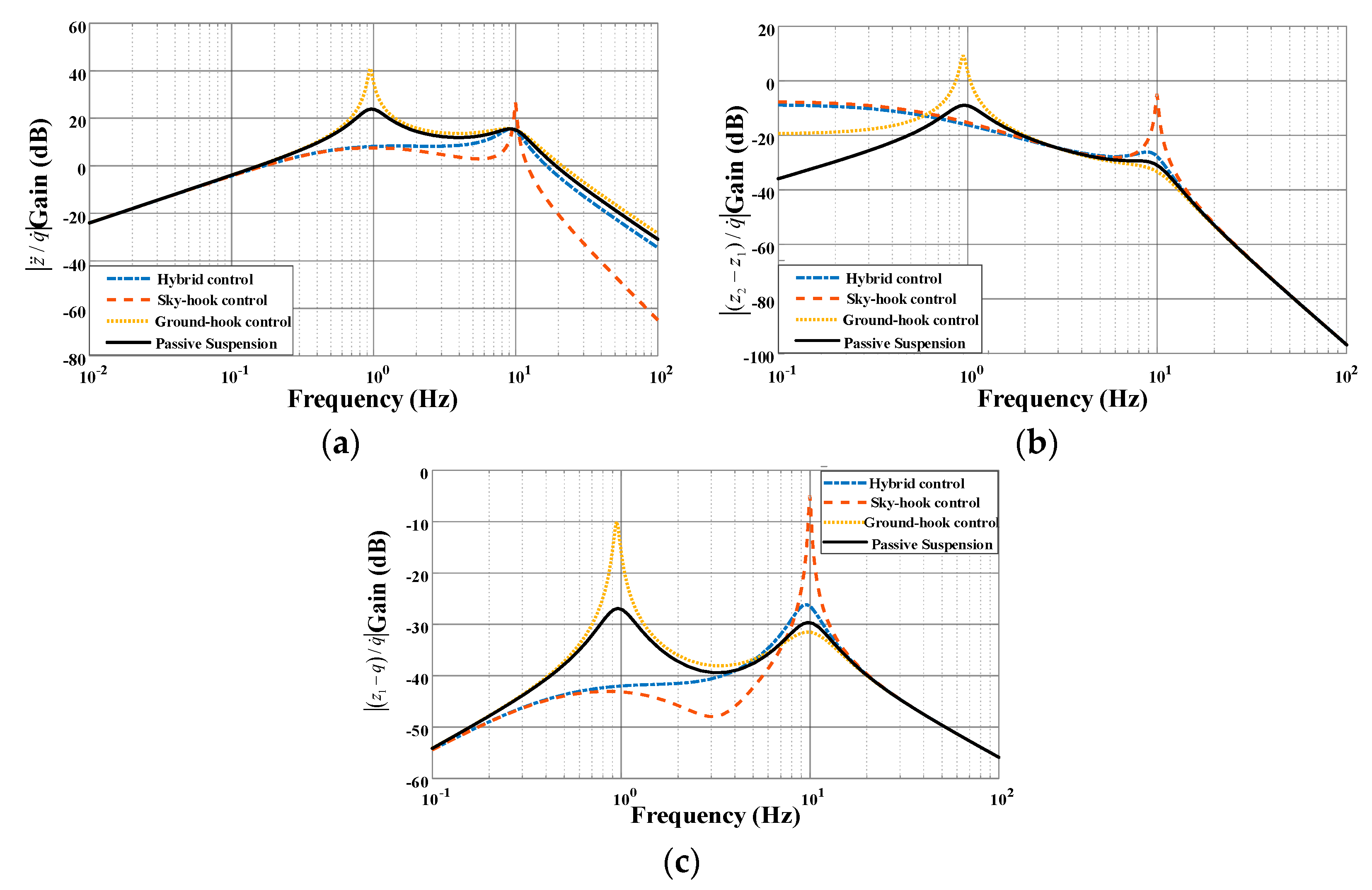
Figure 4.
Relationship between fuzzy sets and extension sets.

Figure 5.
Extension set diagram: (a) T(x) > 0; (b) T(x) < 0.
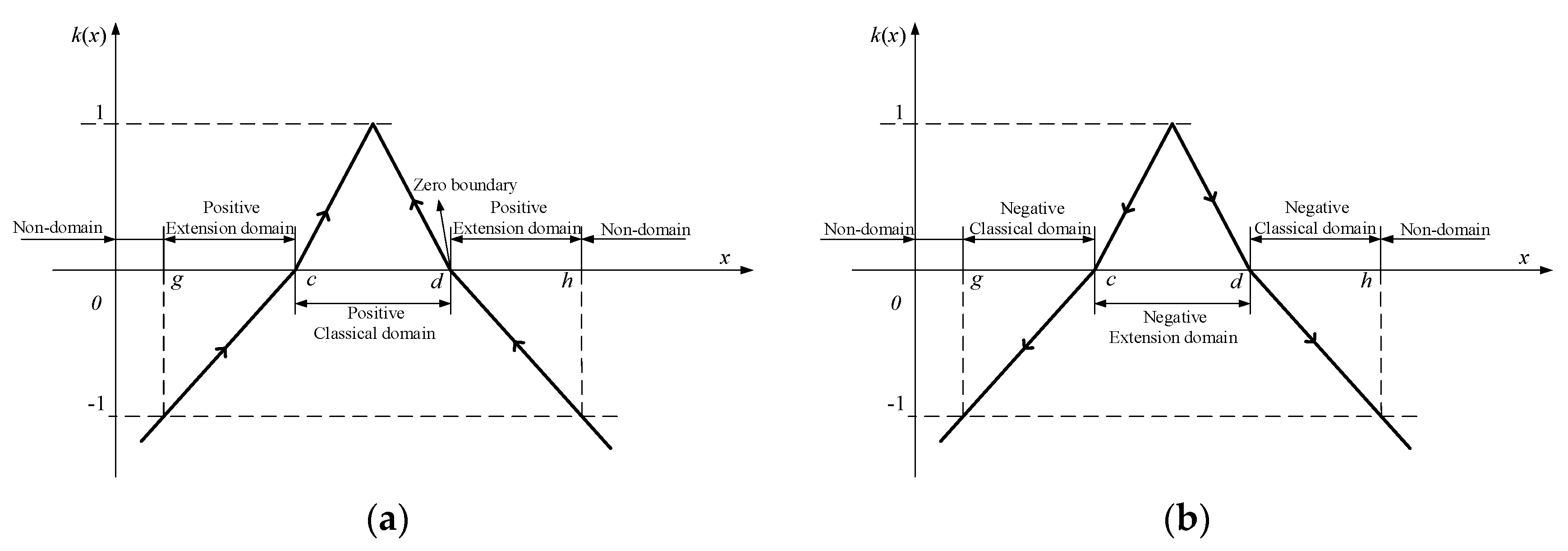
Figure 6.
Hybrid control suspension system.
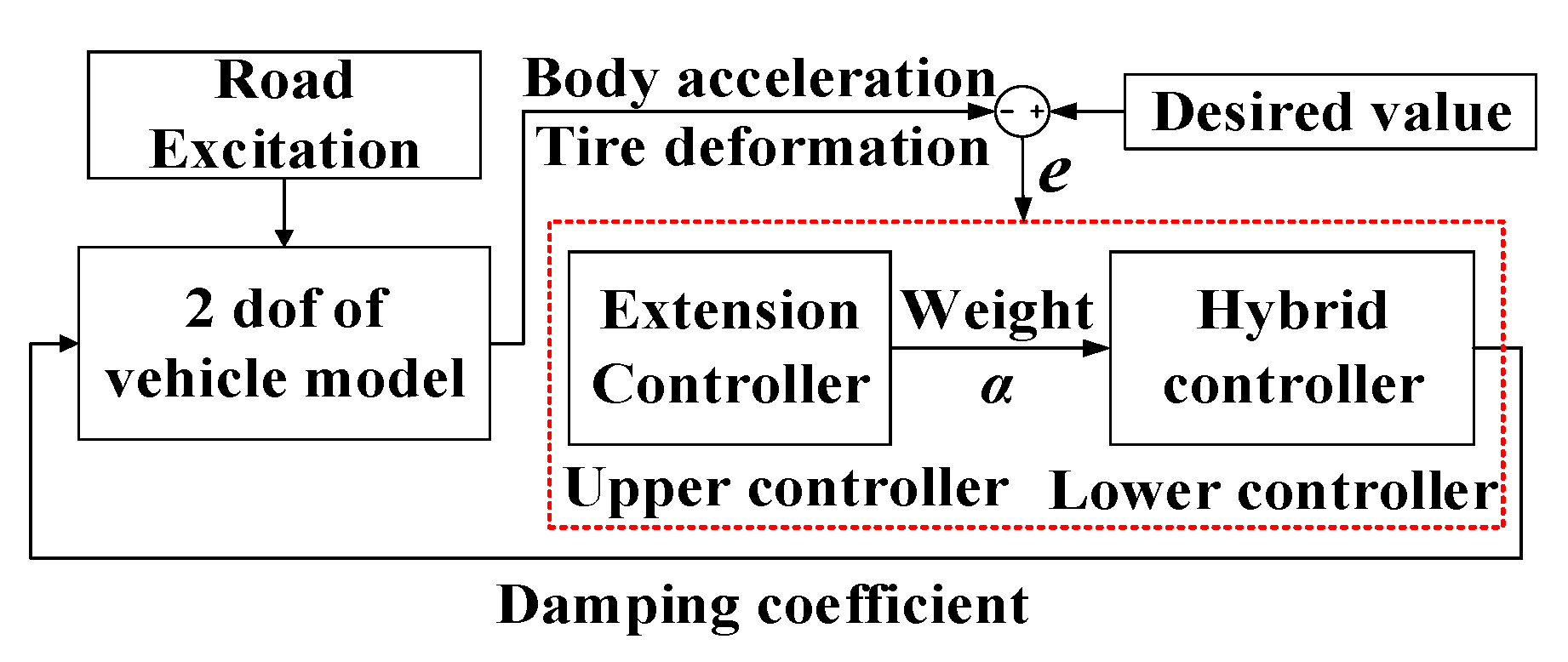
Figure 7.
Extension controller with suspension hybrid control.
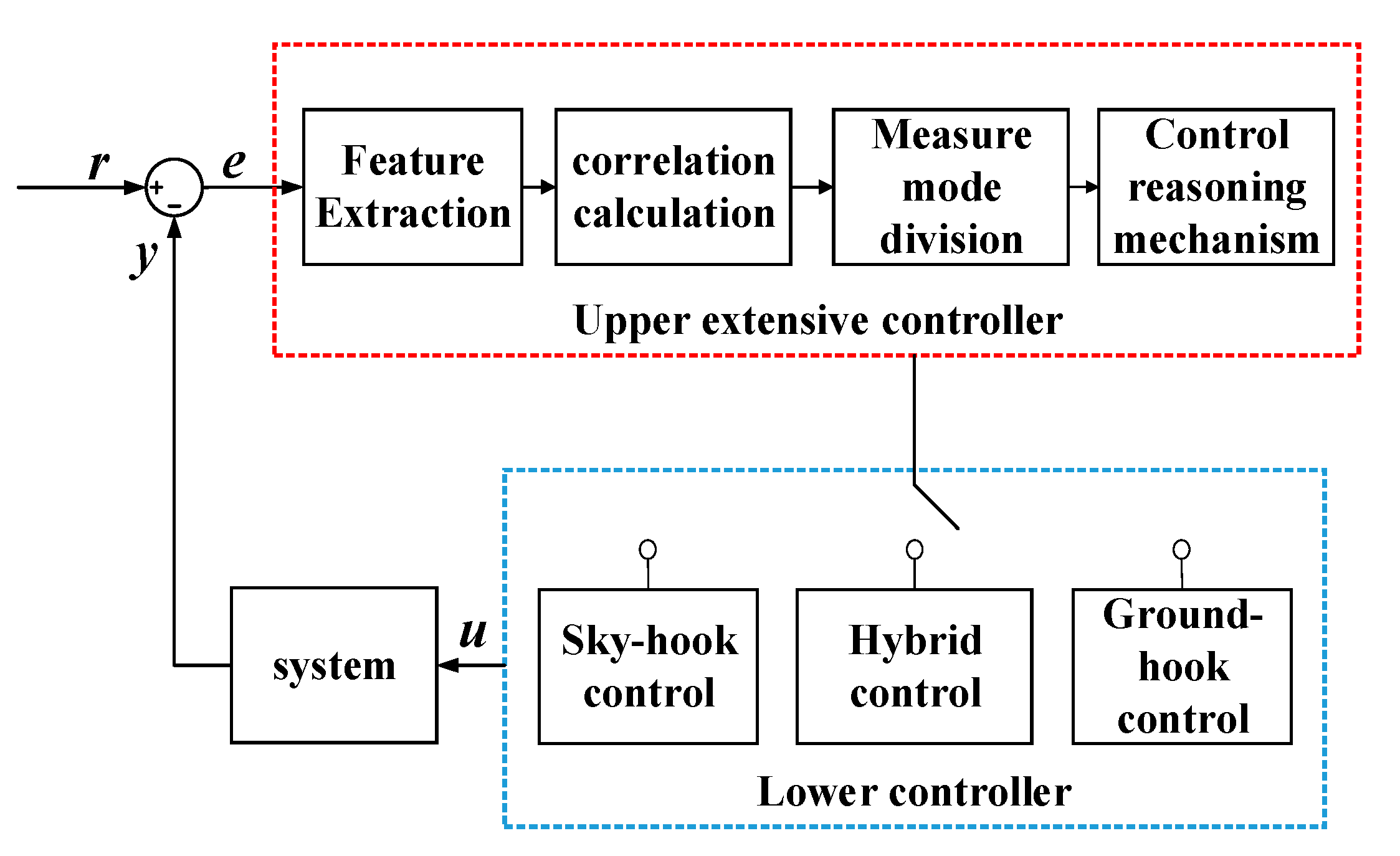
Figure 8.
Extension set characteristic plane.
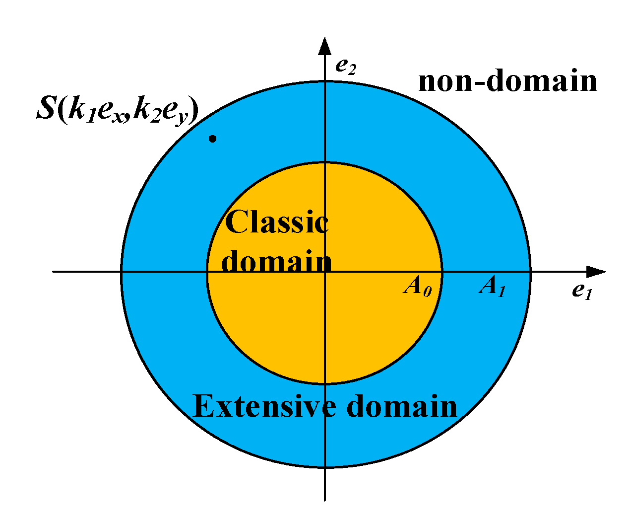
Figure 9.
Correlation function and extension function diagram.

Figure 10.
Sky-hook control.
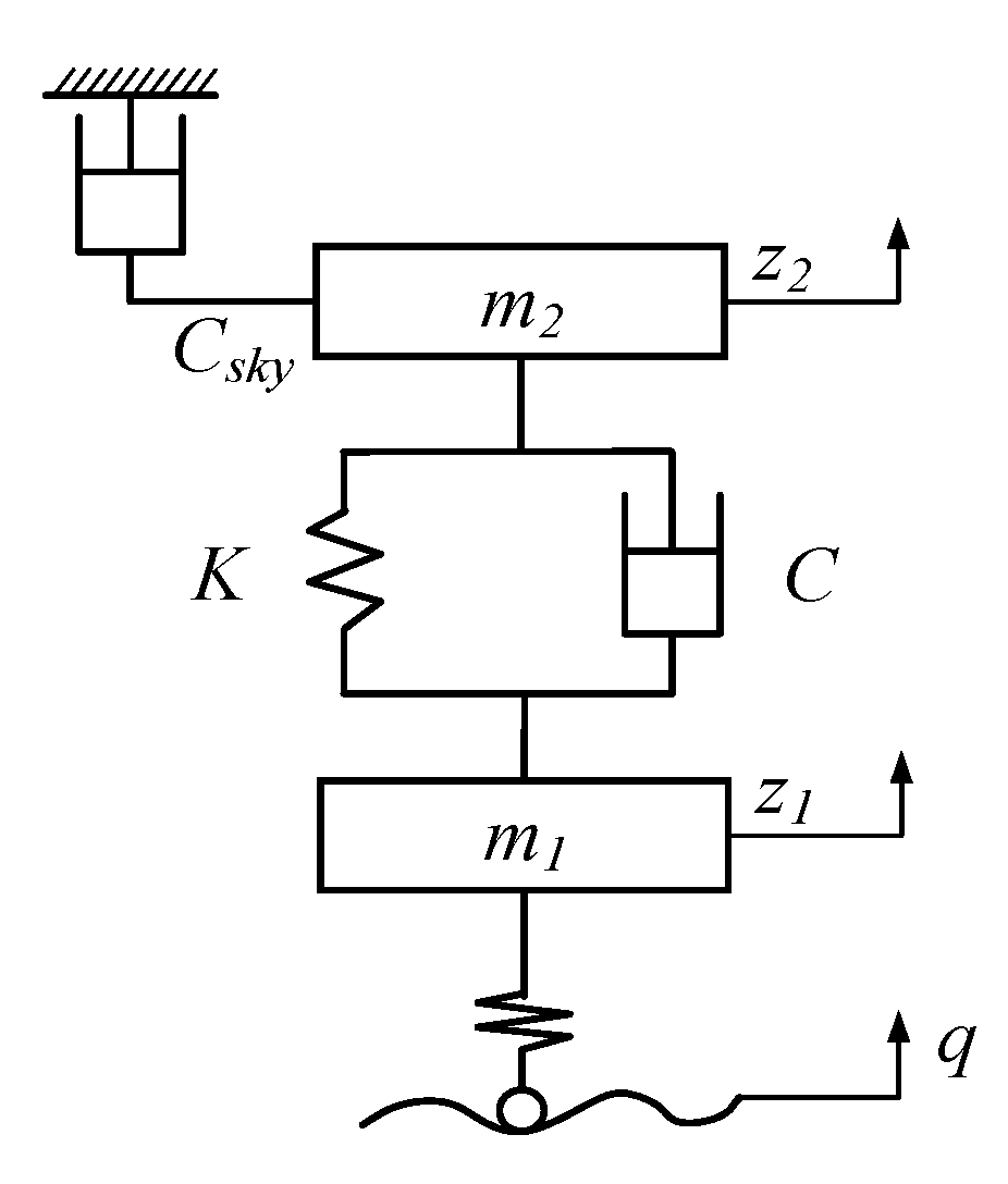
Figure 11.
Ground-hook control.
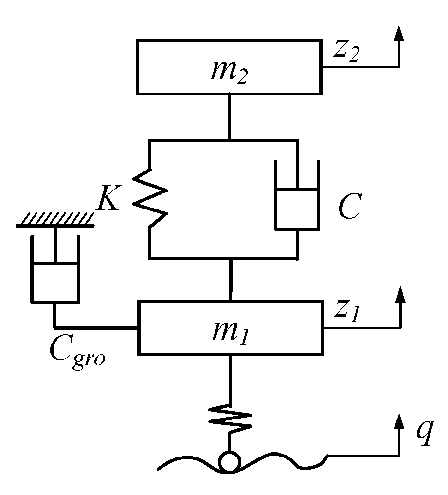
Figure 12.
Flowchart of hybrid control based on extension theory.
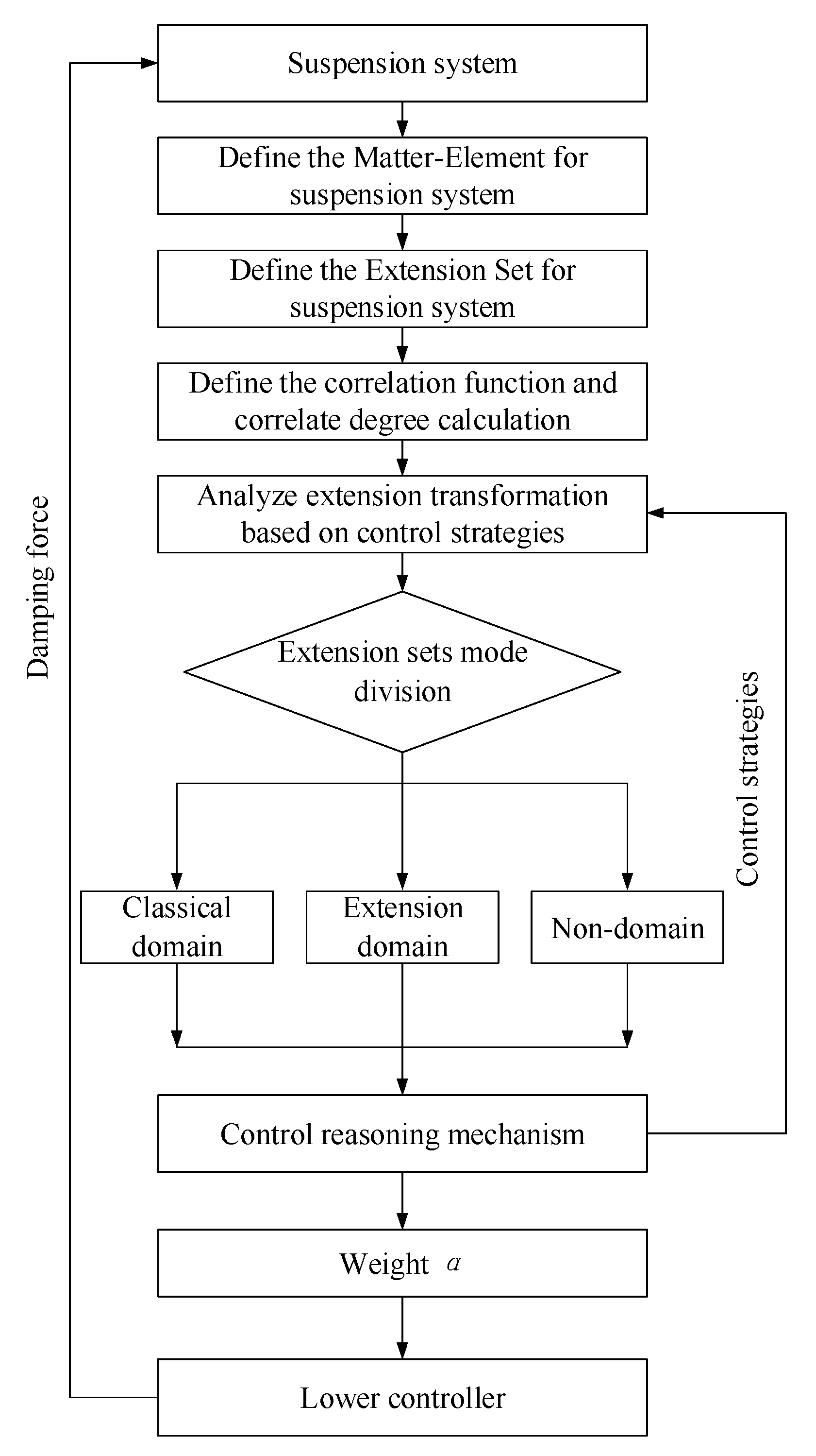
Figure 13.
Simulink model of suspension extension control system.
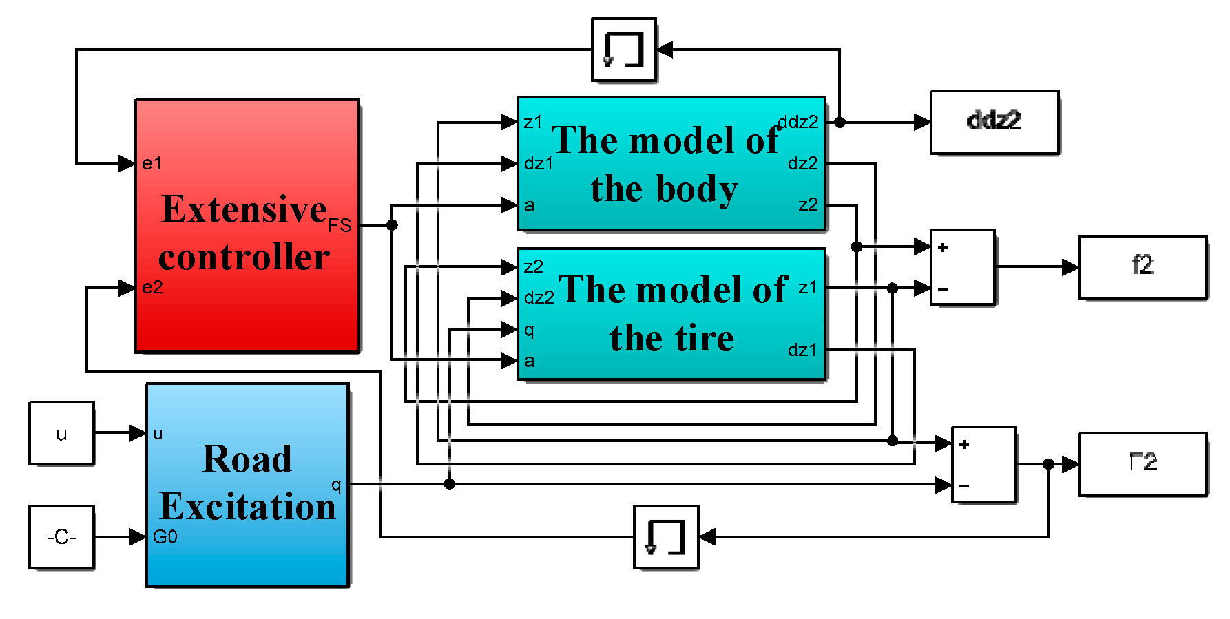
Figure 14.
Comparison of system responses under low-frequency excitation: (a) Body acceleration; (b) Suspension dynamic displacement; (c) Tire dynamic deformation.
Figure 14.
Comparison of system responses under low-frequency excitation: (a) Body acceleration; (b) Suspension dynamic displacement; (c) Tire dynamic deformation.
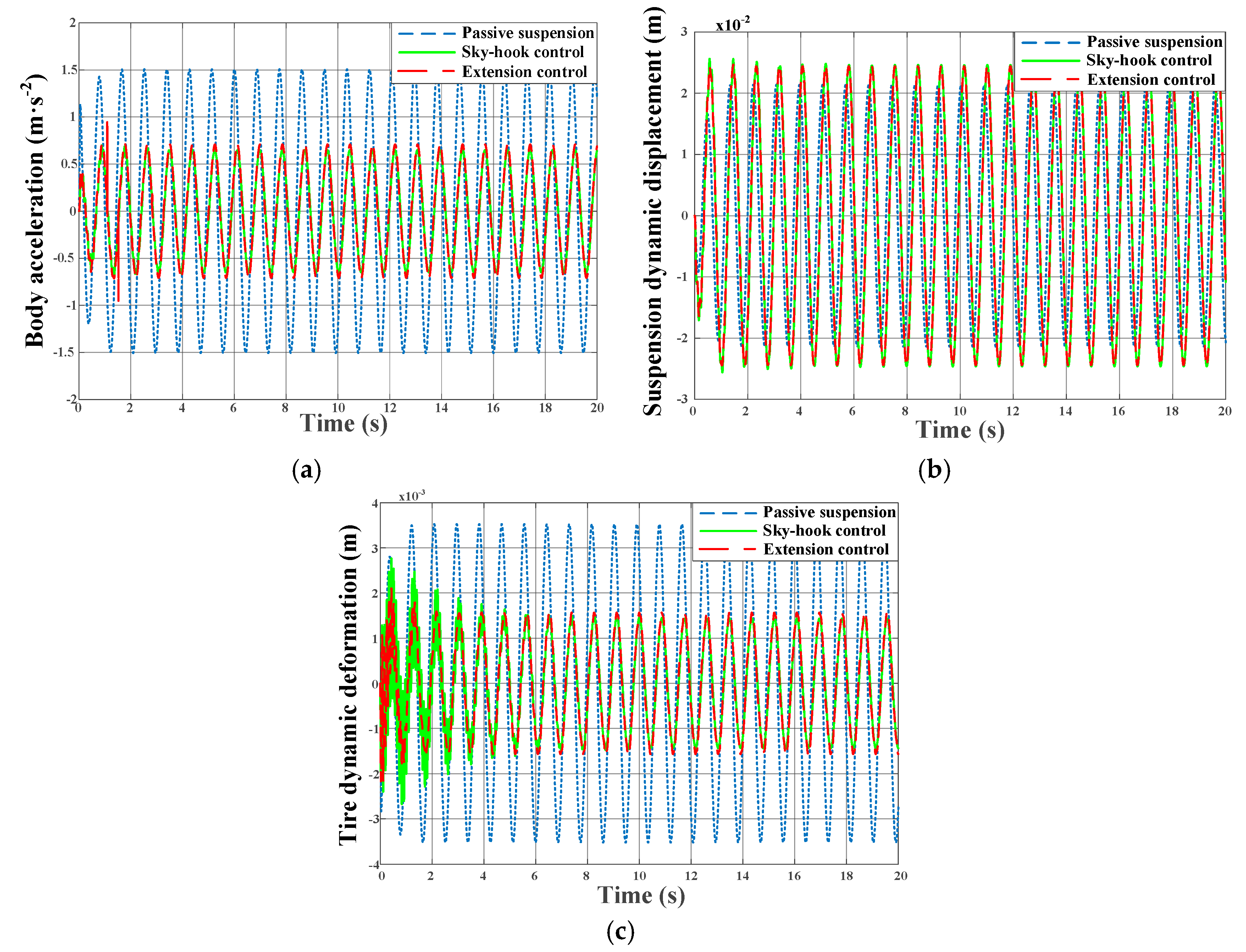
Figure 15.
Distribution weight α under low-frequency excitation.
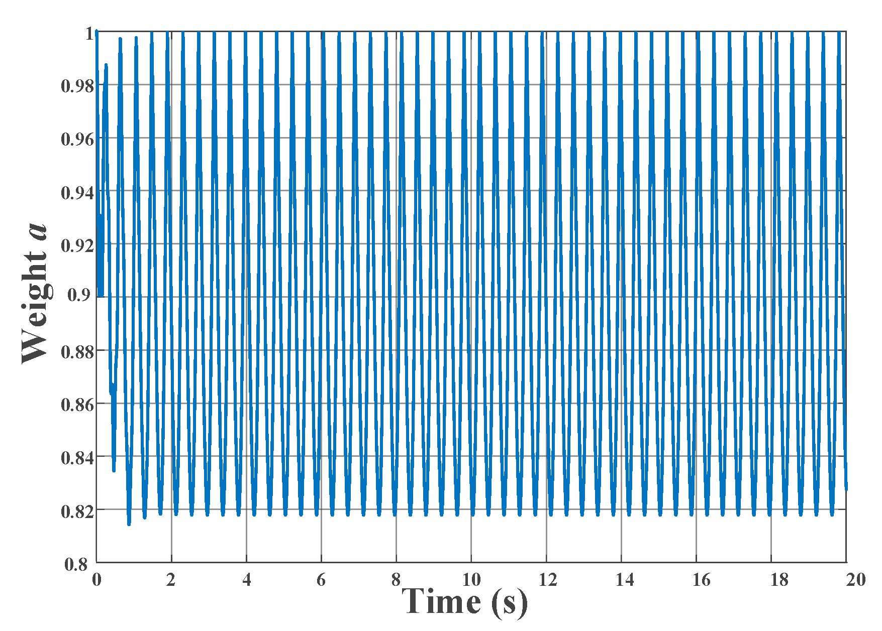
Figure 16.
Comparison of system responses under high frequency excitation: (a) Body acceleration; (b) Suspension dynamic displacement; (c) Tire dynamic deformation.
Figure 16.
Comparison of system responses under high frequency excitation: (a) Body acceleration; (b) Suspension dynamic displacement; (c) Tire dynamic deformation.
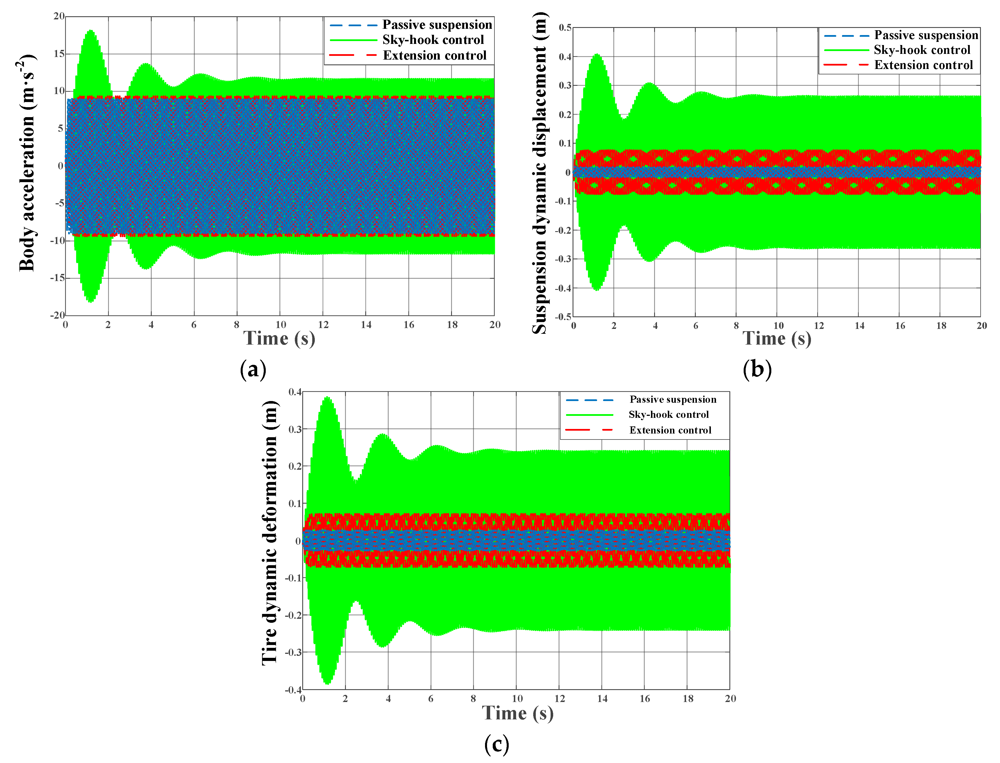
Figure 17.
Distribution weight α under high-frequency excitation.
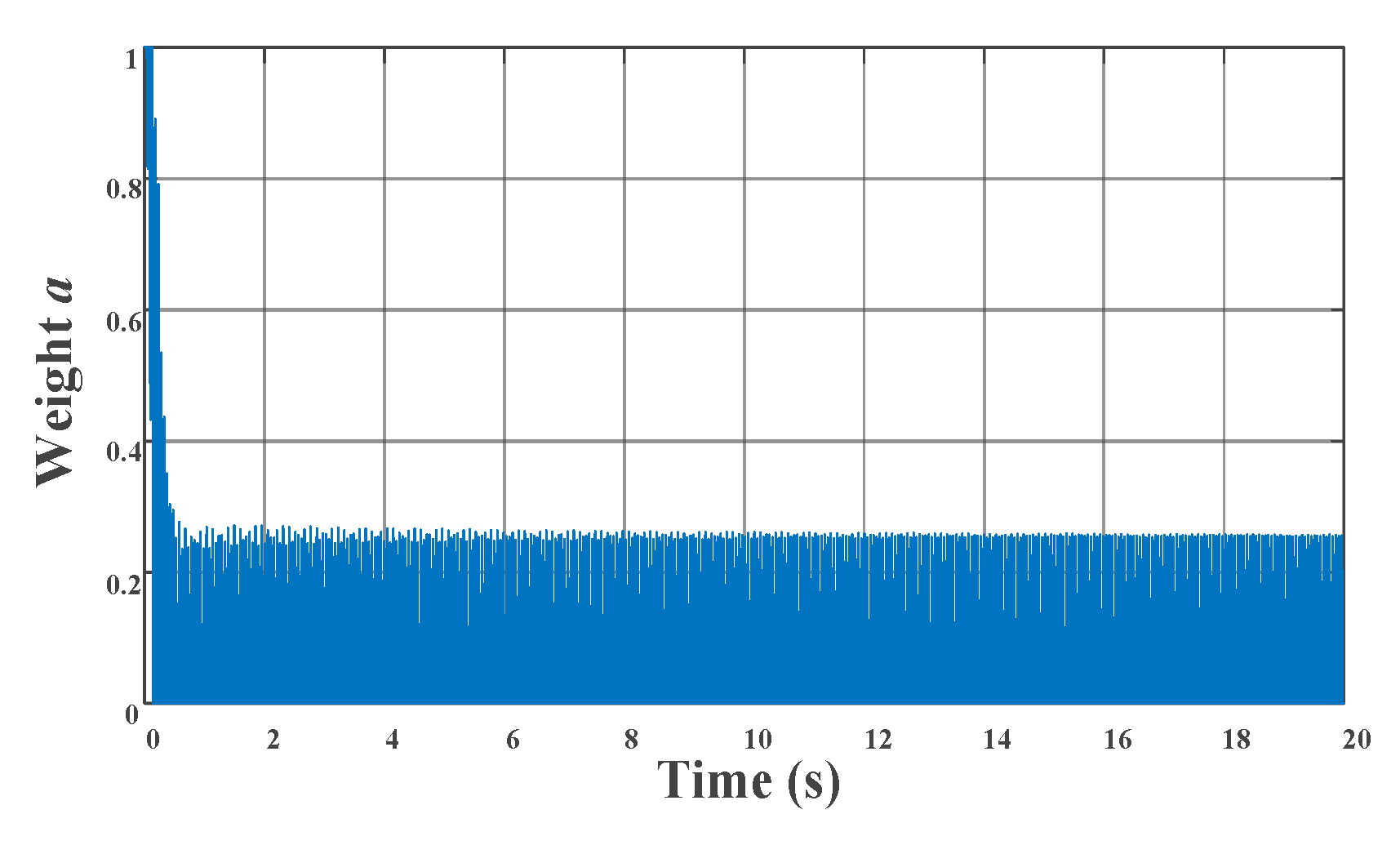
Figure 18.
The ve-DYNA vehicle dynamic model.
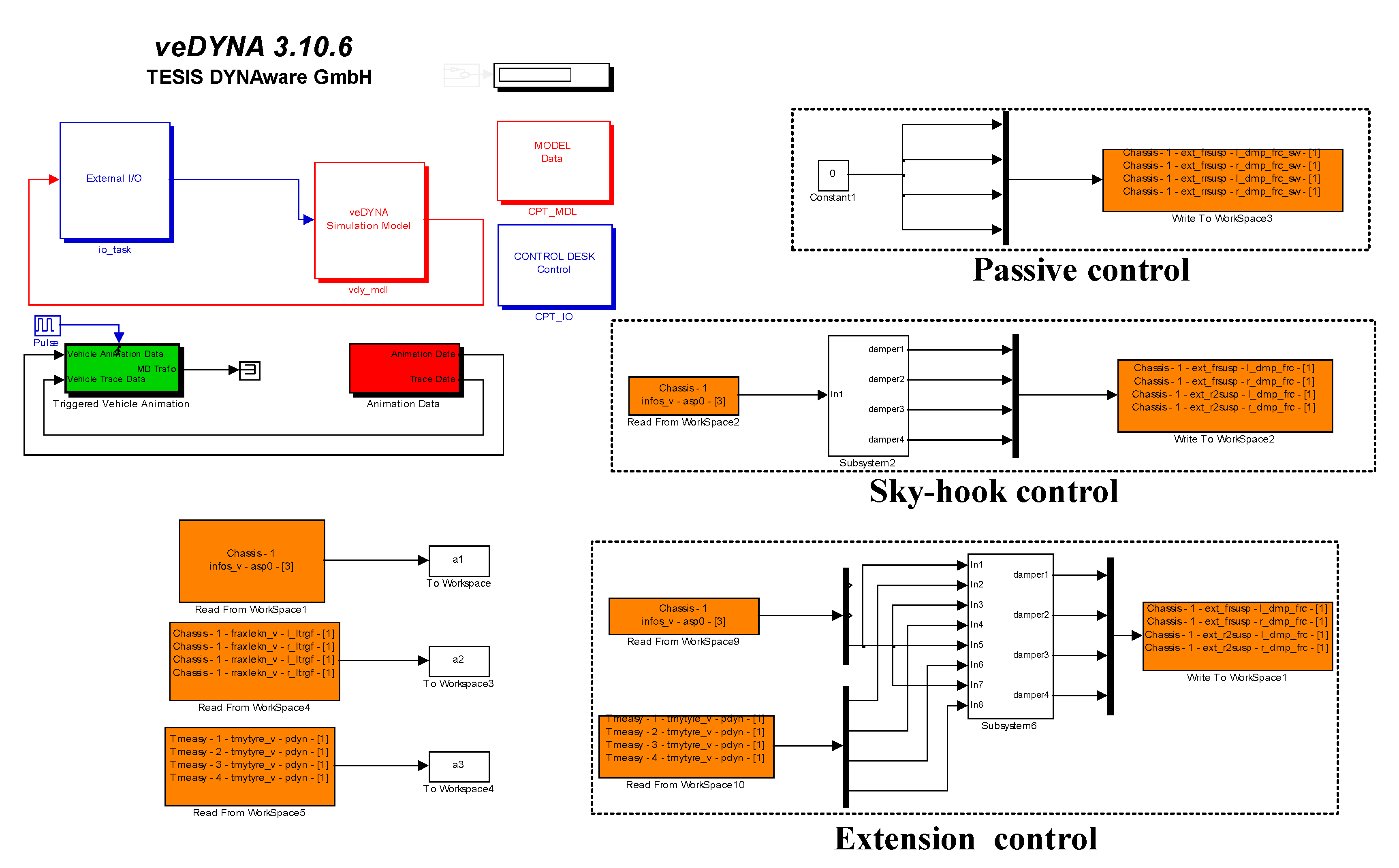
Figure 19.
Parameters setting of the ve-DYNA model.
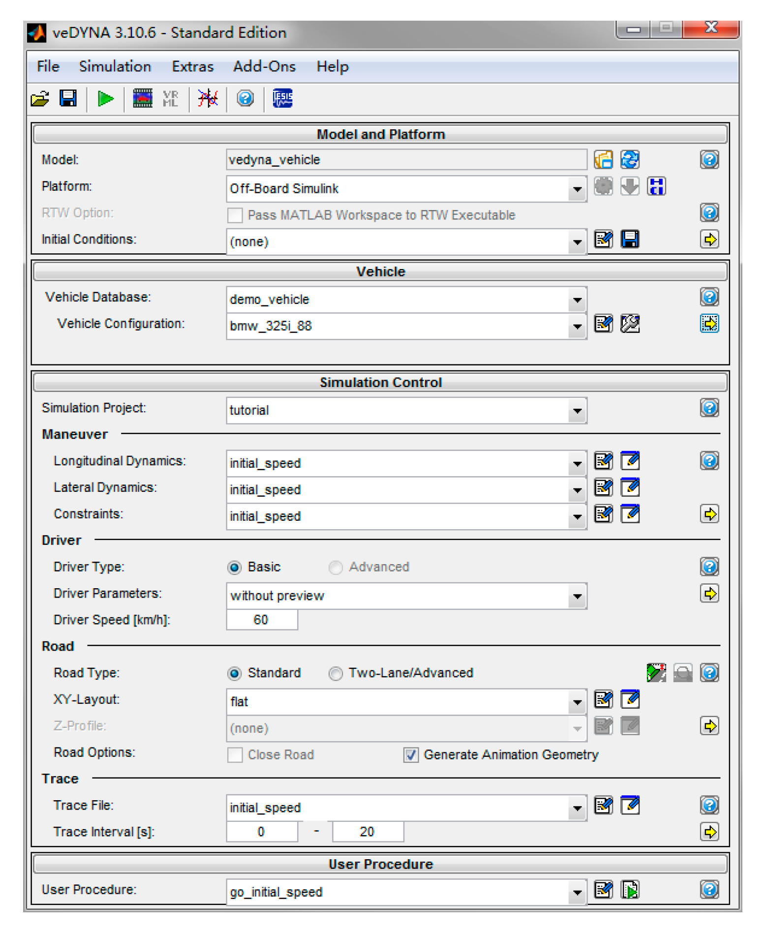
Figure 20.
Weight changes: (a) Front left tire weight; (b) Front right tire weight; (c) Rear left tire weight; (d) Rear right tire weight.
Figure 20.
Weight changes: (a) Front left tire weight; (b) Front right tire weight; (c) Rear left tire weight; (d) Rear right tire weight.

Figure 21.
Comparison of body acceleration under random excitation: (a) Time-domain; (b) Frequency domain.
Figure 21.
Comparison of body acceleration under random excitation: (a) Time-domain; (b) Frequency domain.
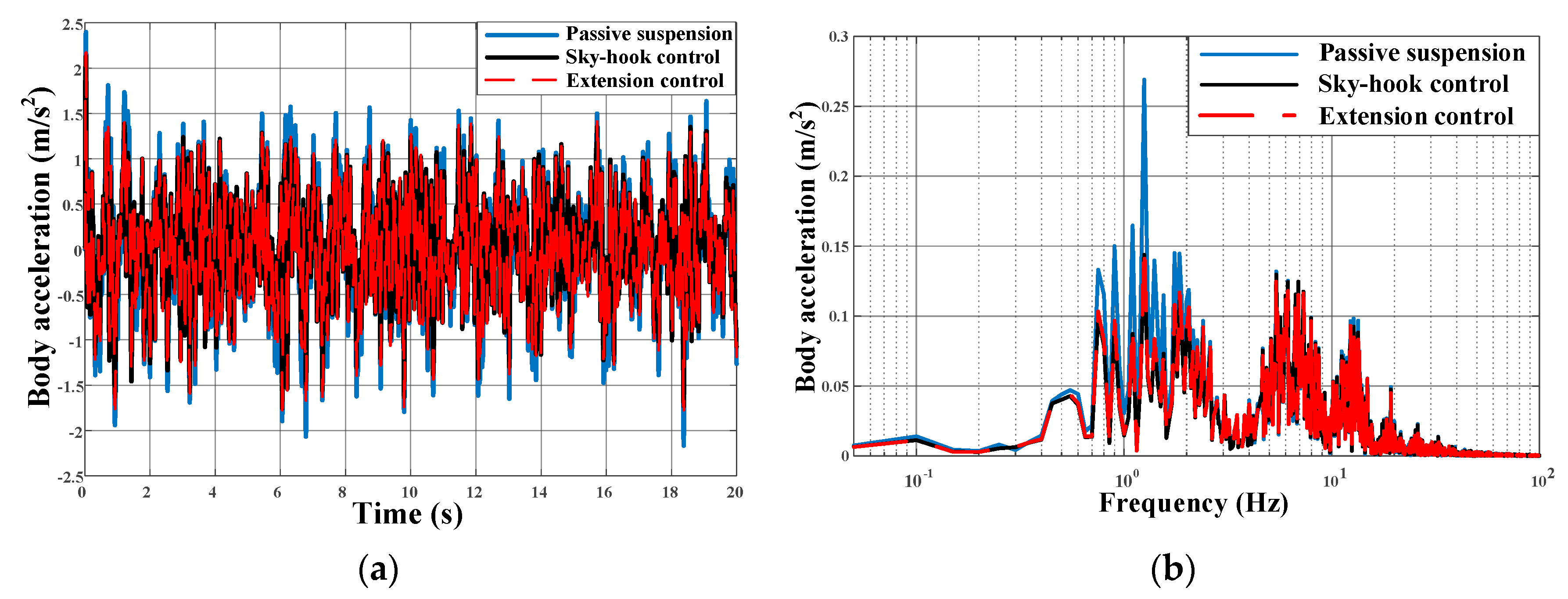
Figure 22.
Comparison of suspension dynamic displacement under random excitation in time domain: (a) Front left tire; (b) Front right tire; (c) Rear left tire; (d) Rear right tire.
Figure 22.
Comparison of suspension dynamic displacement under random excitation in time domain: (a) Front left tire; (b) Front right tire; (c) Rear left tire; (d) Rear right tire.
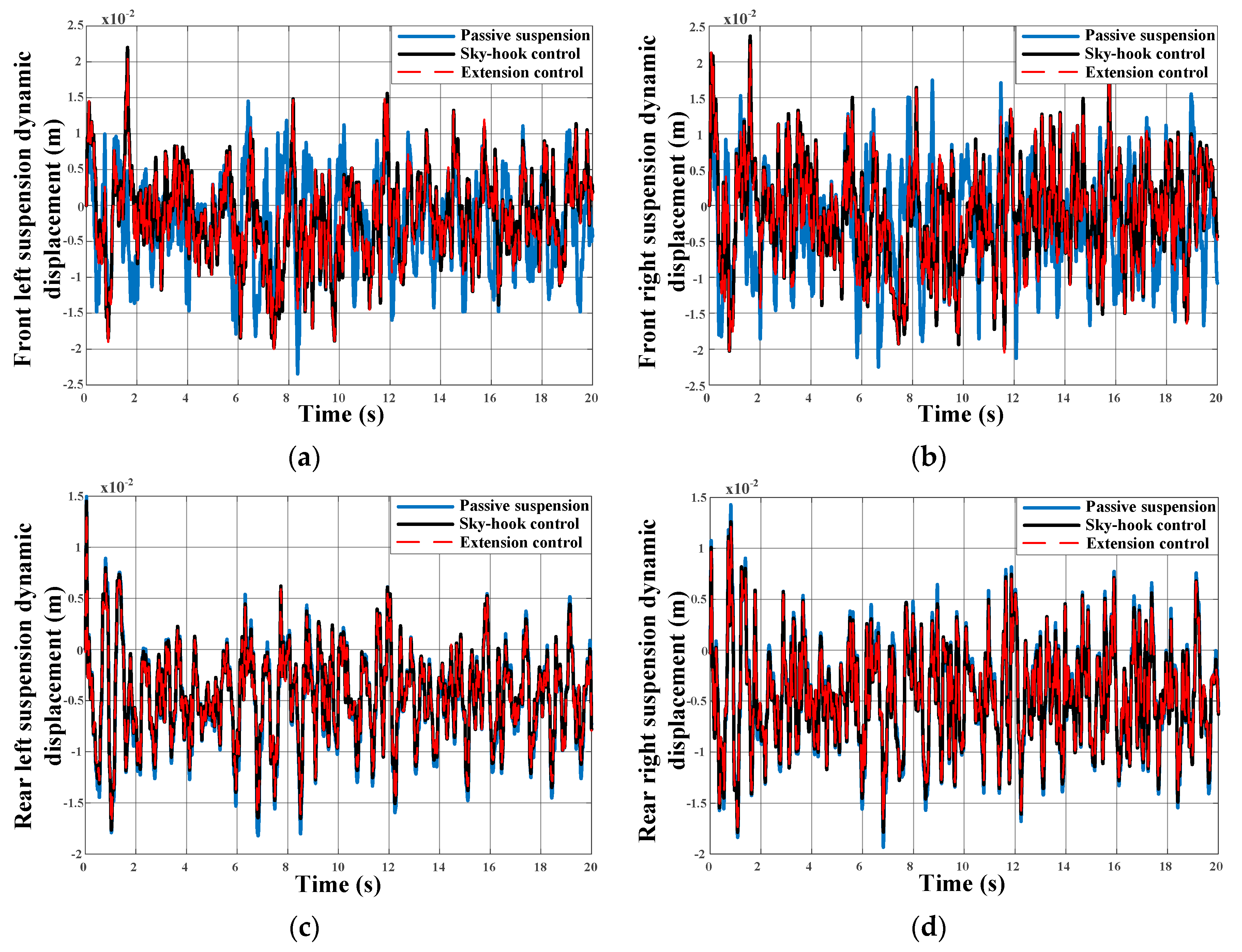
Figure 23.
Comparison of suspension dynamic displacement under random excitation in frequency domain: (a) Front left tire; (b) Front right tire; (c) Rear left tire; (d) Rear right tire.
Figure 23.
Comparison of suspension dynamic displacement under random excitation in frequency domain: (a) Front left tire; (b) Front right tire; (c) Rear left tire; (d) Rear right tire.
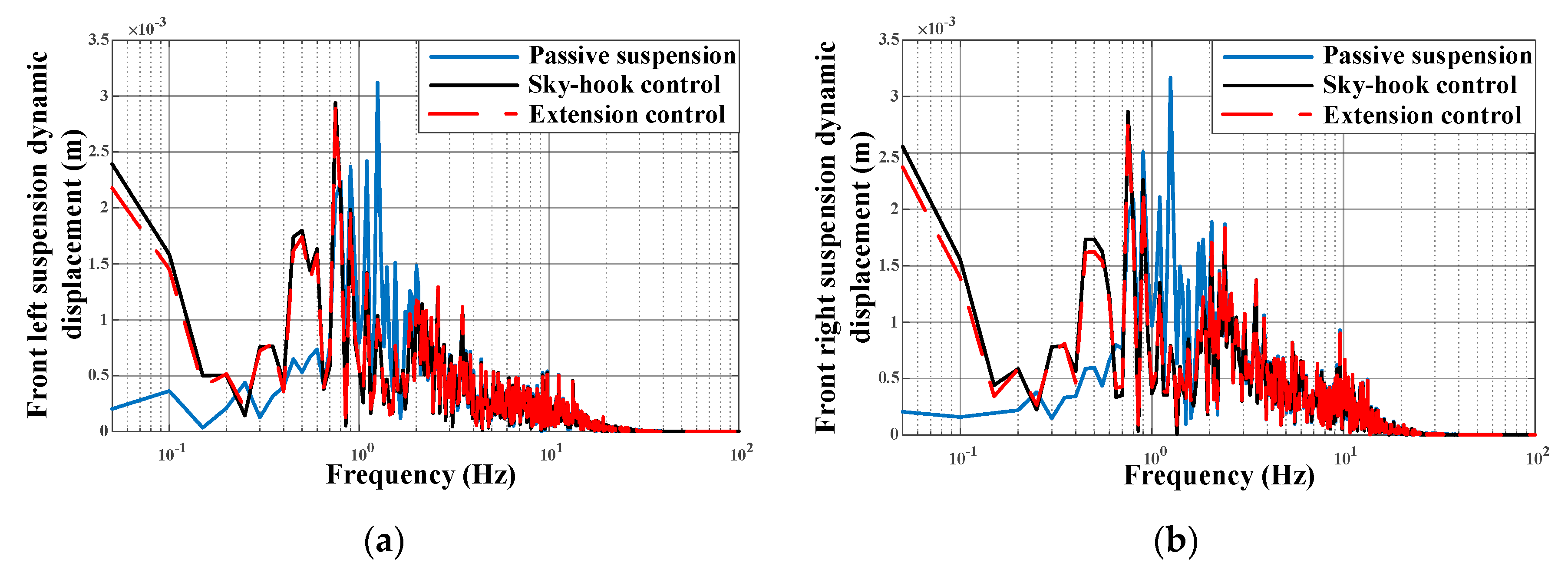
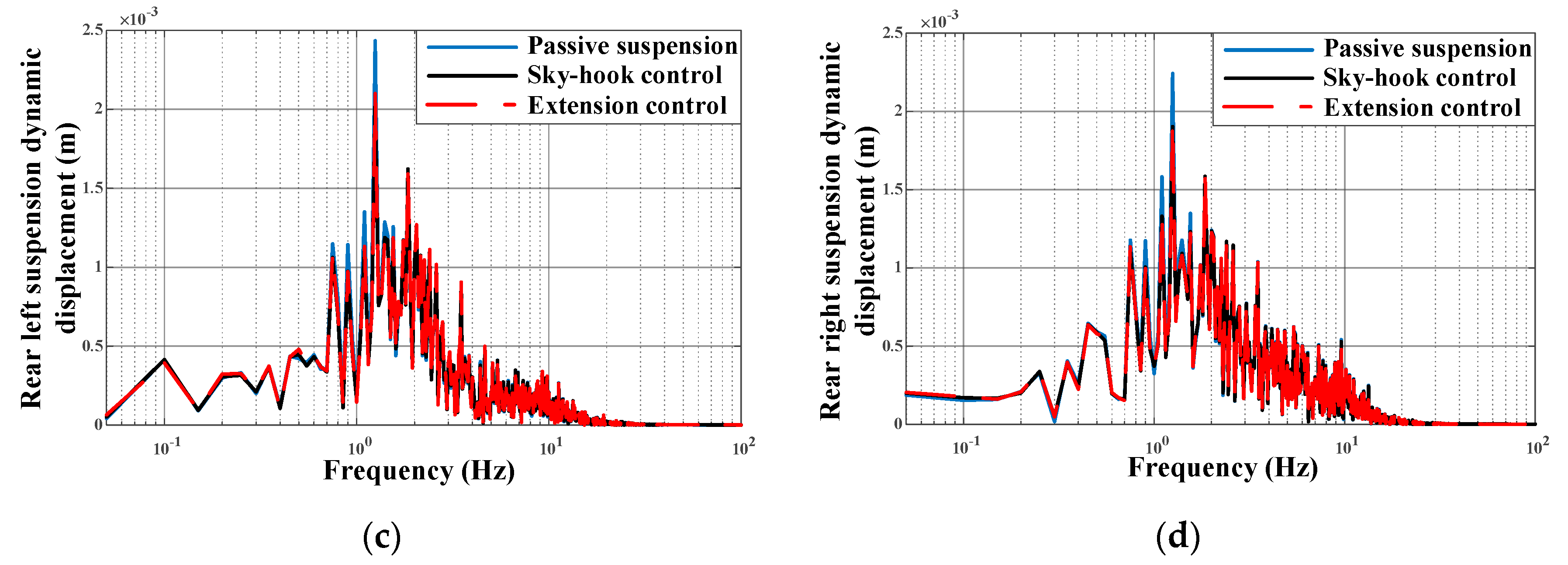
Figure 24.
Comparison of tire dynamic deformation under random excitation in the time domain: (a) Front left tire; (b) Front right tire; (c) Rear left tire; (d) Rear right tire.
Figure 24.
Comparison of tire dynamic deformation under random excitation in the time domain: (a) Front left tire; (b) Front right tire; (c) Rear left tire; (d) Rear right tire.

Figure 25.
Comparison of tire dynamic deformation under random excitation in the frequency domain: (a) Front left tire; (b) Front right tire; (c) Rear left tire; (d) Rear right tire.
Figure 25.
Comparison of tire dynamic deformation under random excitation in the frequency domain: (a) Front left tire; (b) Front right tire; (c) Rear left tire; (d) Rear right tire.

Table 1.
Parameters of the 2-DOF suspension model.
| Parameters | Value |
|---|---|
| Sprung mass M2 (kg) | 400 |
| Unsprung mass M1 (kg) | 40 |
| Tire stiffness Kt (N/m) | 180,000 |
| Suspension stiffness K (N/m) | 18,750 |
| Desired sky-hook damper Csky (N·s/m) | 4000 |
| Desired ground-hook damper Cgro (N·s/m) | 1500 |
Table 2.
Parameters of extension controller.
| Parameters | Value |
|---|---|
| Maximum error of ride comfort under sky-hook control e10lim | 0.016 |
| Maximum error of safety under sky-hook control e20lim | 0.009 |
| Maximum error of ride comfort under sky-hook control e11lim | 1.1 |
| Maximum error of safety under sky-hook control e21lim | 2.5 |
| Factor k1 | 1 |
| Factor k2 | 600 |
Table 3.
Low-frequency responses.
| RMS | Passive Suspension | Sky-Hook Control | Extension Control |
|---|---|---|---|
| Body acceleration (m·s−2) | 1.1175 | 0.4698 | 0.4997 |
| Suspension dynamic displacement (m) | 0.0154 | 0.0174 | 0.0173 |
| Tire dynamic deformation (m) | 0.0026 | 0.0012 | 0.0011 |
Table 4.
High-frequency responses.
| RMS | Passive Suspension | Sky-Hook Control | Extension Control |
|---|---|---|---|
| Body acceleration (m·s−2) | 6.3534 | 8.4417 | 6.5497 |
| Suspension dynamic displacement (m) | 0.0124 | 0.1896 | 0.0533 |
| Tire dynamic deformation (m) | 0.0192 | 0.1444 | 0.0501 |
Table 5.
Results of response under different control methods.
| RMS | Passive Suspension | Sky-Hook Control | Extension Control |
|---|---|---|---|
| Body acceleration (m·s−2) | 0.6823 | 0.5945 | 0.5962 |
| Front left suspension dynamic displacement (m) | 0.0068 | 0.0064 | 0.0063 |
| Front right suspension dynamic displacement (m) | 0.0078 | 0.0072 | 0.0072 |
| Rear left suspension dynamic displacement (m) | 0.0067 | 0.0066 | 0.0066 |
| Rear right suspension dynamic displacement (m) | 0.0069 | 0. 0068 | 0.0068 |
| Front left tire dynamic deformation (m) | 0.01822 | 0.01803 | 0.01713 |
| Front right tire dynamic deformation (m) | 0.01840 | 0.01820 | 0.01749 |
| Rear left tire dynamic deformation (m) | 0.01773 | 0.01762 | 0.01702 |
| Rear right tire dynamic deformation (m) | 0.01777 | 0.01766 | 0.01702 |
© 2020 by the authors. Licensee MDPI, Basel, Switzerland. This article is an open access article distributed under the terms and conditions of the Creative Commons Attribution (CC BY) license (http://creativecommons.org/licenses/by/4.0/).
Share and Cite
MDPI and ACS Style
Geng, G.; Yu, Y.; Sun, L.; Li, H. Research on Ride Comfort and Driving Safety under Hybrid Damping Extension Control for Suspension Systems. Appl. Sci. 2020, 10, 1442. https://doi.org/10.3390/app10041442
AMA Style
Geng G, Yu Y, Sun L, Li H. Research on Ride Comfort and Driving Safety under Hybrid Damping Extension Control for Suspension Systems. Applied Sciences. 2020; 10(4):1442. https://doi.org/10.3390/app10041442
Chicago/Turabian StyleGeng, Guoqing, Yi Yu, Liqin Sun, and Hao Li. 2020. "Research on Ride Comfort and Driving Safety under Hybrid Damping Extension Control for Suspension Systems" Applied Sciences 10, no. 4: 1442. https://doi.org/10.3390/app10041442
Note that from the first issue of 2016, this journal uses article numbers instead of page numbers. See further details here.