Experimental Investigations on the Effects of Fatigue Crack in Urban Metro Welded Bogie Frame


1
School of Mechanical, Electronic and Control Engineering, Beijing Jiaotong University, Beijing 100044, China
2
State Key Laboratory of Traction Power, Southwest Jiaotong University, Chengdu 610031, China
3
CRRC Qing Dao SiFang Co., Ltd., Qingdao 266111, China
*
Author to whom correspondence should be addressed.
Appl. Sci. 2020, 10(4), 1537; https://doi.org/10.3390/app10041537
Submission received: 5 February 2020
/
Revised: 17 February 2020
/
Accepted: 20 February 2020
/
Published: 24 February 2020
(This article belongs to the Special Issue Fracture and Fatigue Assessments of Structural Components)
Abstract
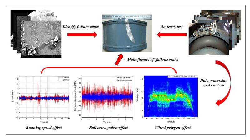
:The welded bogie frame is the critical safety part of the urban metro vehicle. This paper focuses on finding out the factors inducing the fatigue cracks initiated from the positioning block weld toe of metro bogie frame. Fracture morphology and metallographic analysis were conducted to identify the failure modes, and on-track tests about the dynamic stress at the positioning block weld toe and vibration acceleration were performed. The typical signals of dynamic stress and acceleration were analyzed from time and frequency domain. The relationship between wheel polygon, rail corrugation, running speed and dynamic stress in amplitude and frequency are investigated in details. Research results show that the micro cracks induced by welding at the weld toe of positioning block propagate to the spring sleeve under relatively high alternating dynamic stress, which is strongly influenced by the wheel polygon, rail corrugation and the train running speed.

1. Introduction
With the rapid urbanization and industrialization of China society, a huge metro rail network has been building and running in recent years. By the end of 2019, the operating mileage of China urban rail transit has reached about 6600 km and the vehicles in service have reached more than 35,000. As the most important load-carrying structure for railway vehicles, the welded bogie frame undergoes complex fatigue loads [1,2]. Under such alternating loads, the safety critical zone inside the frame necessarily experiences cumulated fatigue damage which seriously threatens the operation safety of rail passenger vehicles [3,4,5].
As frequently observed in metro vehicle frames, fatigue cracks are usually initiated from the welded region of the bogie frame due to complex operation loads. Recently, a fatigue crack in the Shinkansen train bogie frame [6] was found with a total length of 44 mm, which is regarded as a serious incident in the Japan Railway system, which could possibly have led to a derailment. Compared with high-speed railway passenger trains with covering super long distances and time, the urban metro vehicles are used to experiencing more abnormal loading due to frequent start-stops and huge passenger uncertainty. Therefore, lots of failures have come out in recent years, for example fatigue cracks observed near the motor suspension seat, beam and positioning block, etc. [7,8].
The initiation mechanism of fatigue cracks has been investigated extensively, with the critical attention to rail corrugation in terms of the causes, measurements and solutions [9,10,11]. The rail corrugation with the fatigue crack in primary coil springs was tentatively correlated with structural vibration in experiments and simulations [12]. A linear model of the corrugation of rails was established to reveal the relationship between the initial wheel and rail roughness and the wear rate spectra in the contact patch [13]. The initiation and evolution of rail short-pitch corrugation and the effect on wheelset vibration were further investigated by using the field test and simulations to eliminate the corrugation [14].
Another argued aspect to buffer the fatigue crack is the wheel polygonalization traditionally found in high-speed railway wheels [15,16,17,18]. By considering the real wheel out-of-roundness, the considerably fluctuating wheel/rail contact force was observed from a vertical vehicle-track coupled dynamics model [17]. Similarly, by using on-site experiments and simulations, the mechanism of metro wheel polygonal wear was carefully explored at the speed of 65–75 km/h and suggested that the wheelset flexibility could accelerate the polygonal wear and abnormal vibration [19,20]. Such an irregular wheel profile was reasonably believed to produce a detrimental effect on the railway axle and bogie frame [21,22,23].
With regard to the crack of bogie frame [24,25], initial works have been made through multi-body dynamic system [26] and finite element simulations [27]. In this paper, on-track tests including the dynamic stress and acceleration were performed under different loading conditions to elucidate the cracking mechanism of metro bogie frames. By combining time, frequency and time-frequency domain analyses, the factors inducing the cracks are confirmed and measures are proposed to prevent such similar failures.
2. Experimental Methods
2.1. Cracking Site and Fracture Analysis
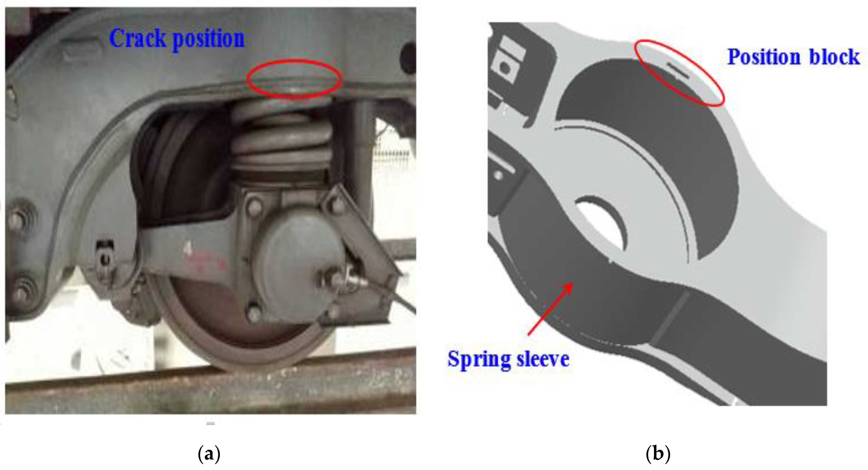
A crack was found at the spring sleeve of one metro bogie frame (as shown in Figure 1a) and the service life is less than 200,000 km. The spring sleeve of the frame side beam is welded by upper cover, lower cover and circular plate. The positioning block is welded to the spring sleeve lower cover by four welds, as seen in Figure 1b. The crack initiated from the weld toe of the positioning block and then propagated to the spring sleeve circular plate with maximum 110 mm in length, as shown in Figure 1c,d.
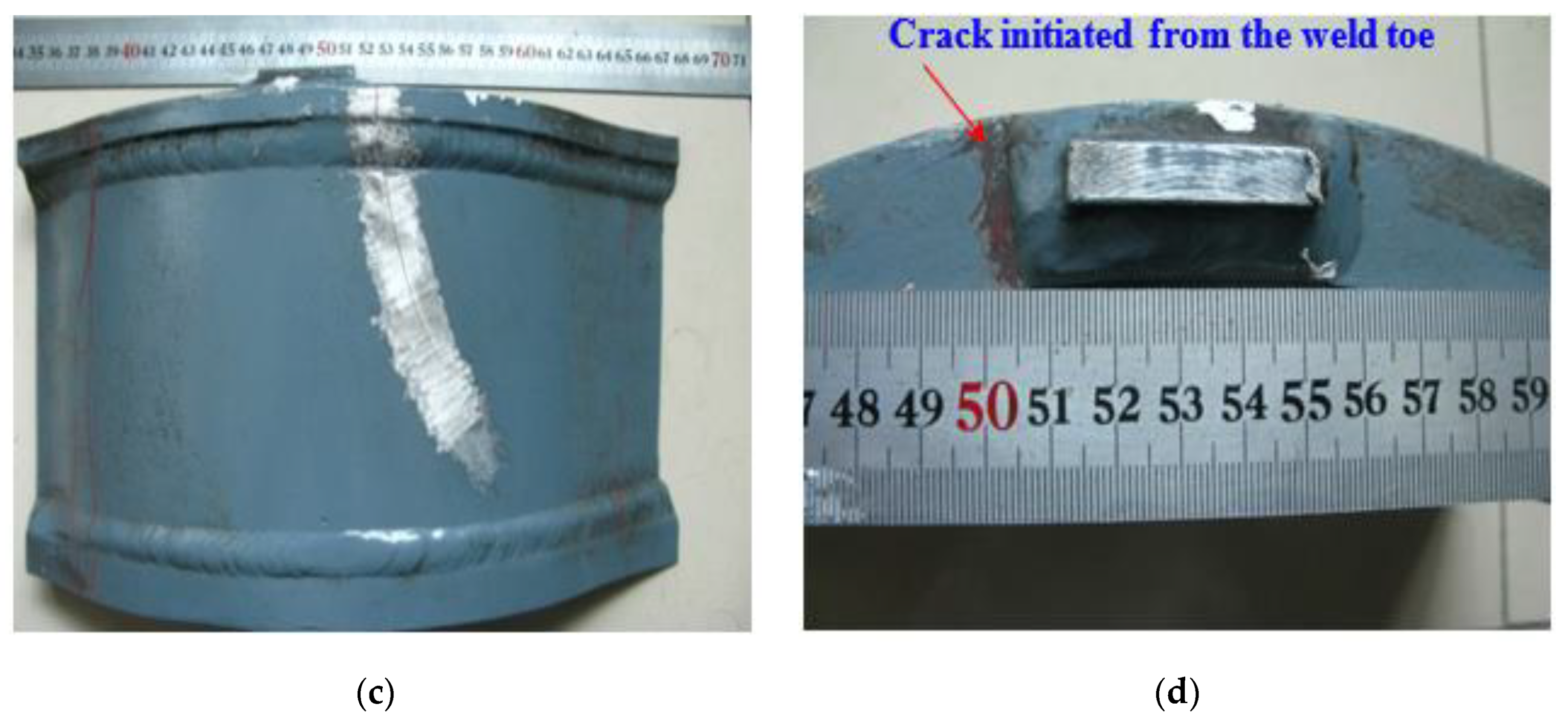
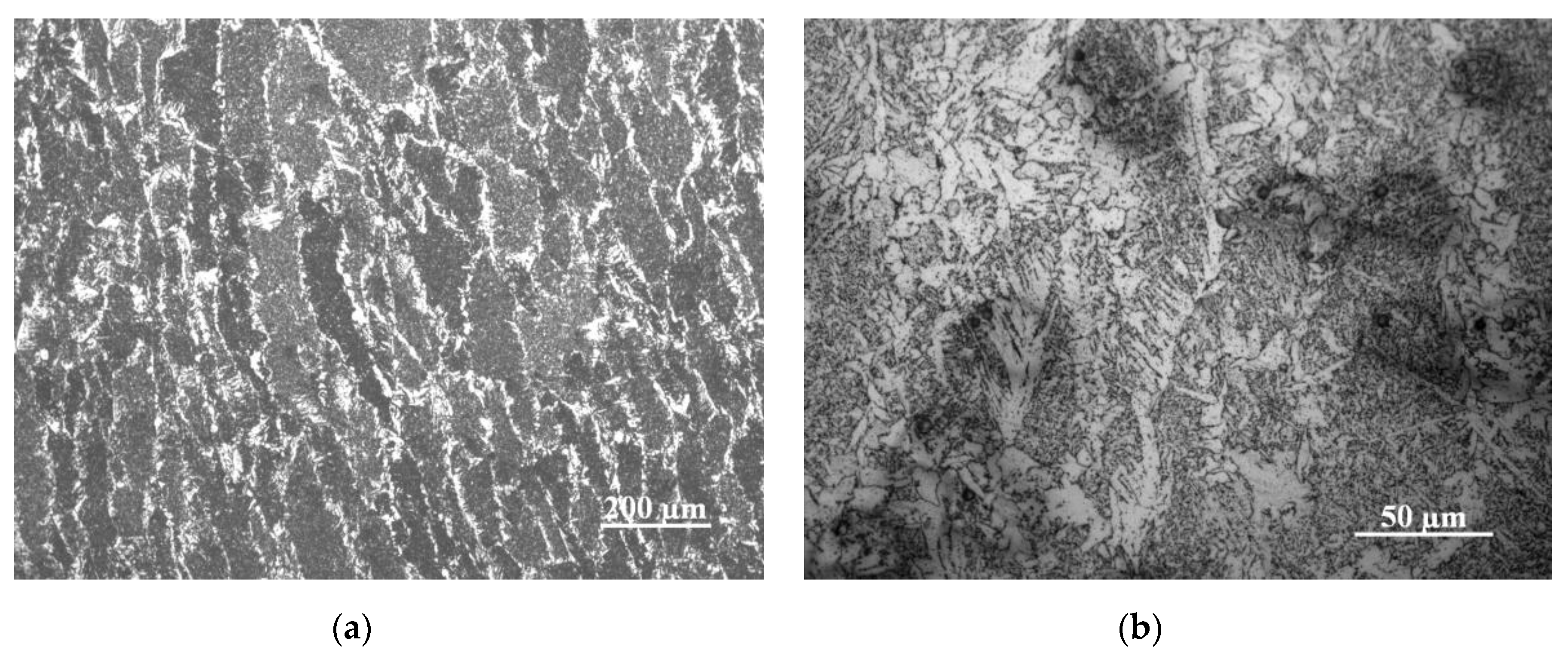
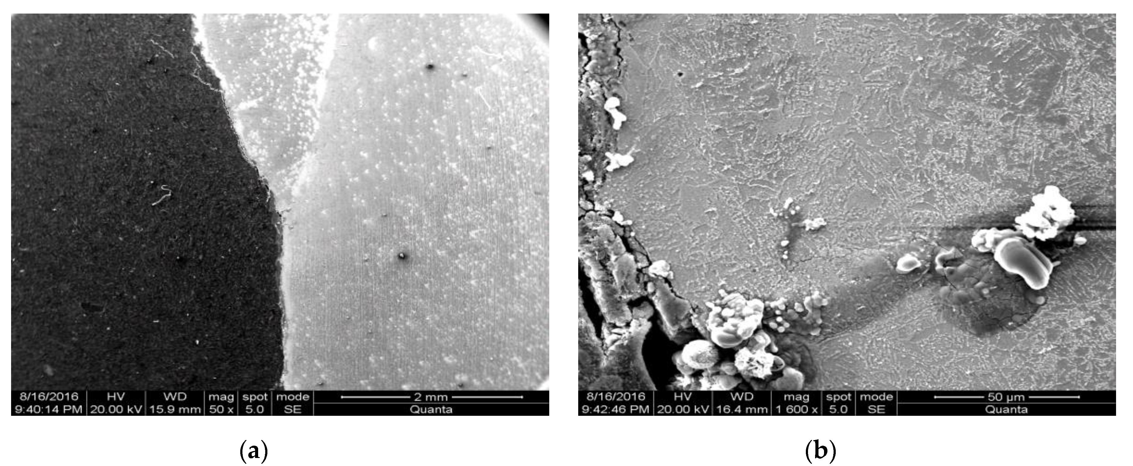
The fracture morphology of the cracking zone was examined by scanning electron microscopy (SEM) as shown in Figure 2. It can be clearly observed that some parallel marks are available near the weld toe, which indicates a notable fatigue damage feature during operation. Metallographic specimens were thus prepared at the critical cracking position. Columnar grains were clearly found in the weld and the heat-affected zone, which are composed of lamella ferrite and featherlike widmanstatten structures, as shown in Figure 3. The SEM observation of weld toe shows that the micro crack starts from the surface of the lower plate and propagates internally, and it includes several discontinuous sections and branches appear around the main crack (Figure 4).
2.2. On-Track Tests
In order to precisely acquire the failure causes and stress characteristics of the failed region in the metro vehicle bogie frame, both dynamic stress and vibration acceleration tests were firstly carried out under the following three operation conditions considering the wheel roundness, rail corrugation and the train running speed, as listed in Table 1.
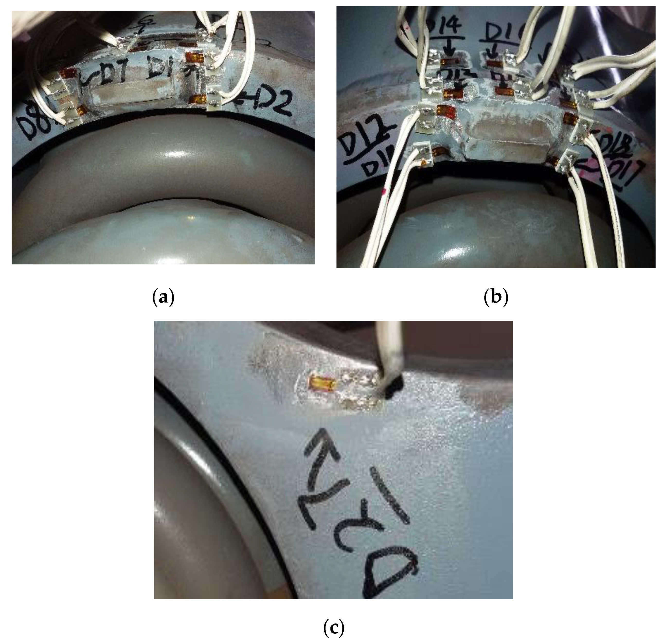
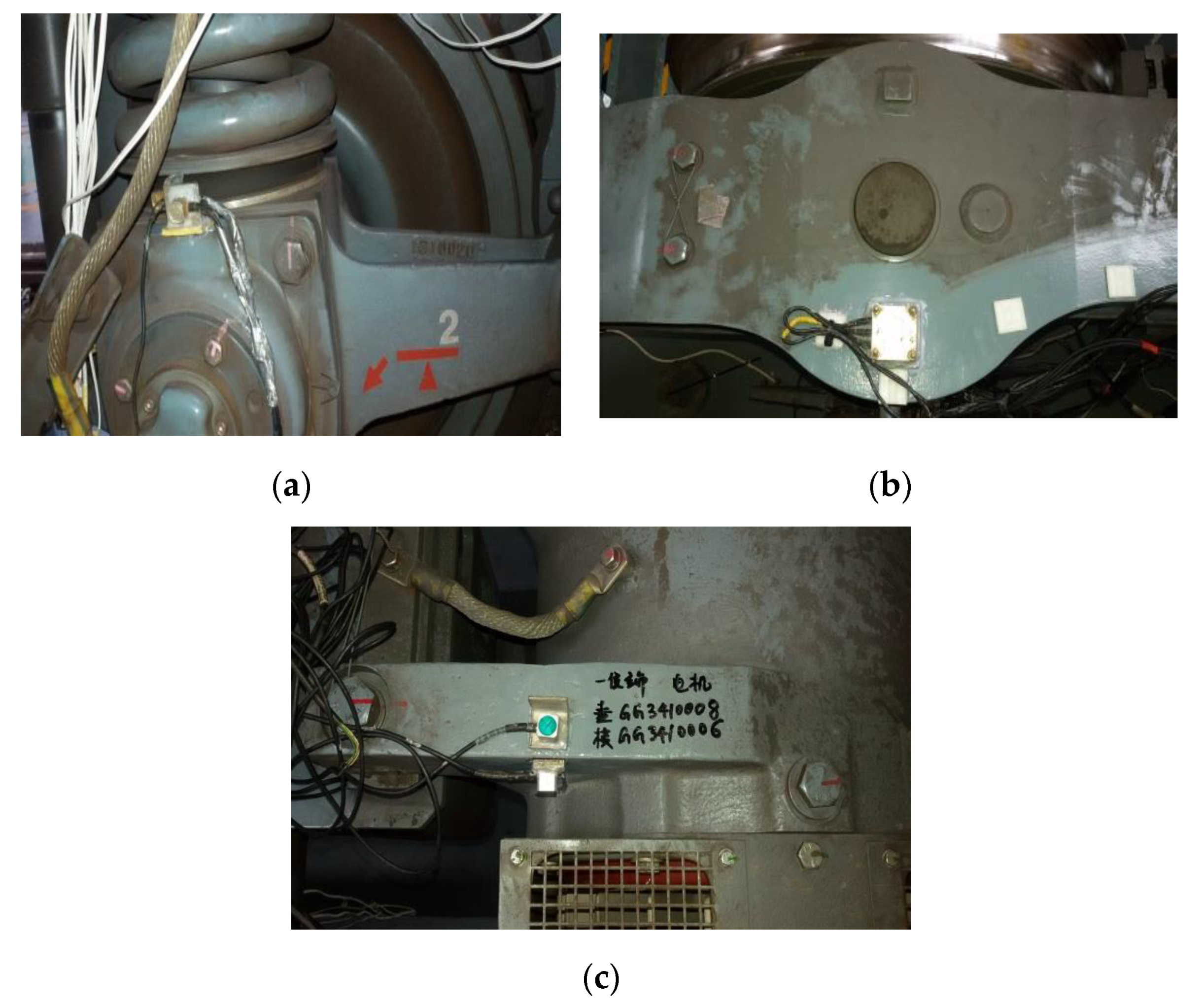
Digital dynamic signal acquisition system (IMC) was employed in this investigation due to its high precision and fast response during the whole process. The dynamic stress and acceleration sampling frequencies were set to 2500 Hz to ensure the completeness and reliability of the test data. The dynamic stress testing points (denoted such as D2, D11, D17) were mounted around the positioning block as a critical zone and on the lower cover of the side beam (such as D27), as shown in Figure 5. Note that points D02/ D11/ D17 were specially designed vertically to the weld toe of positioning block because mode I crack was generally assumed in engineering applications. The acceleration sensors were fixed on the axle box, spring sleeve and the motor, respectively, to measure the vibration induced by wheel-rail excitation, as shown in Figure 6.
2.2.1. Dynamic Stress Test
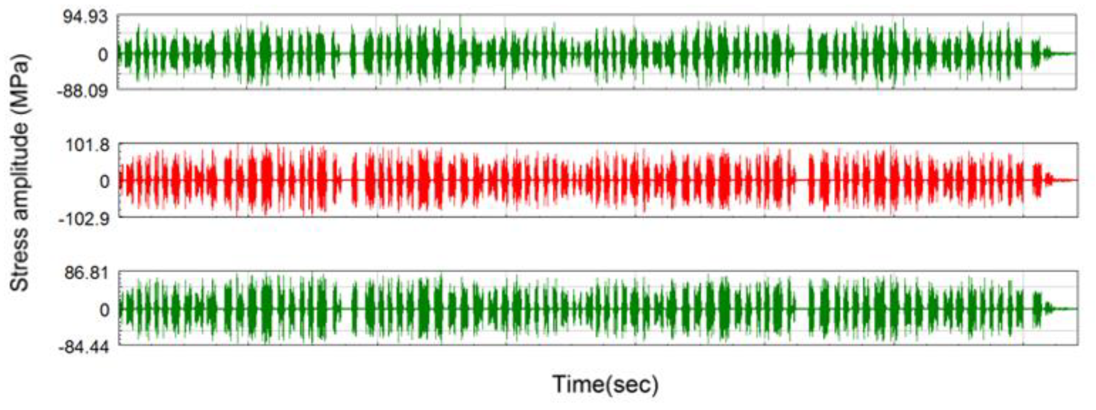
The full-range dynamic stress waveforms of point D02, D11 and D17 are shown in Figure 7. The maximum stress amplitudes of D02, D11 and D17 are 91.5 MPa, 102.4 MPa and 85.6 MPa respectively. According to the stress-time history of each point, the stress spectrum can be obtained by adopting rain-flow counting method. Thus, with S-N curve and Miner’s rule of accumulative damage, the damage of each point can be calculated. The results indicate that the damages of these testing points at the weld toe of positioning block are all larger than 1, which provide evidence of initiation and propagation of fatigue crack.
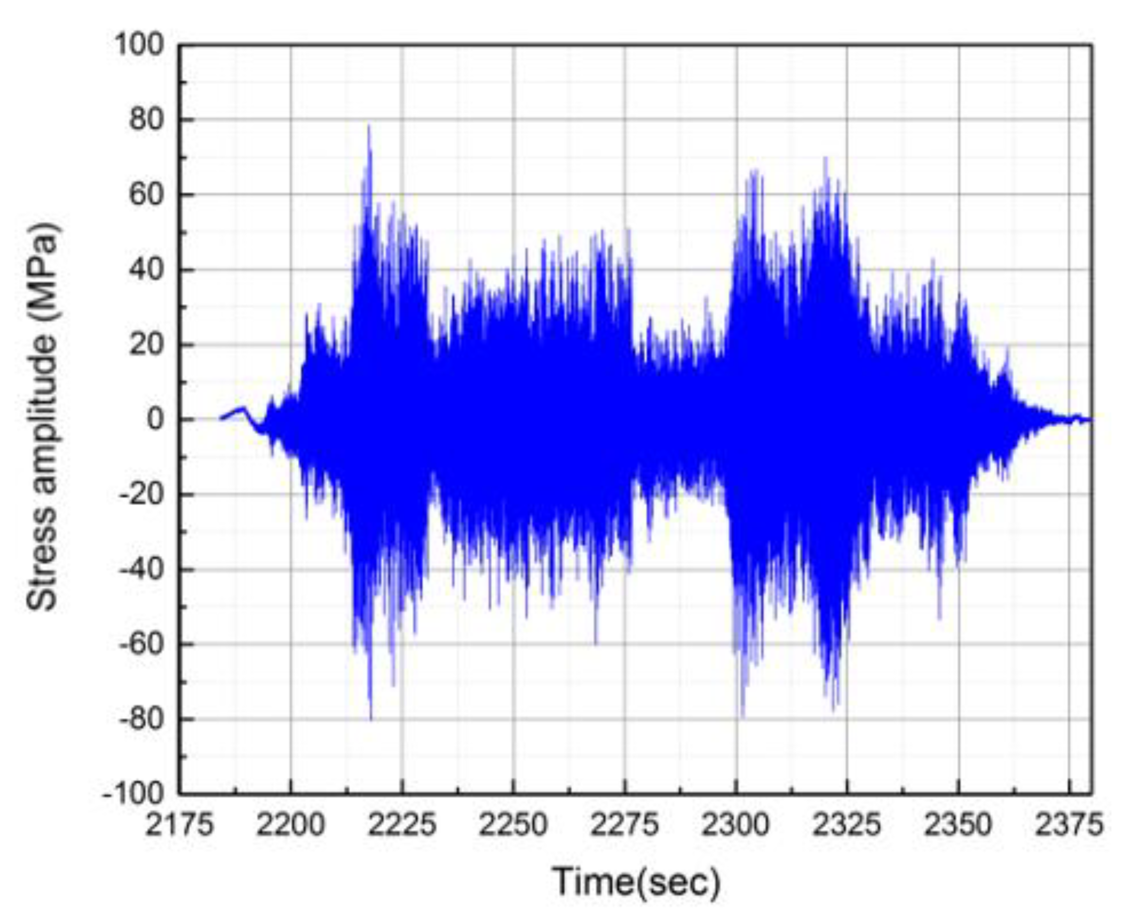
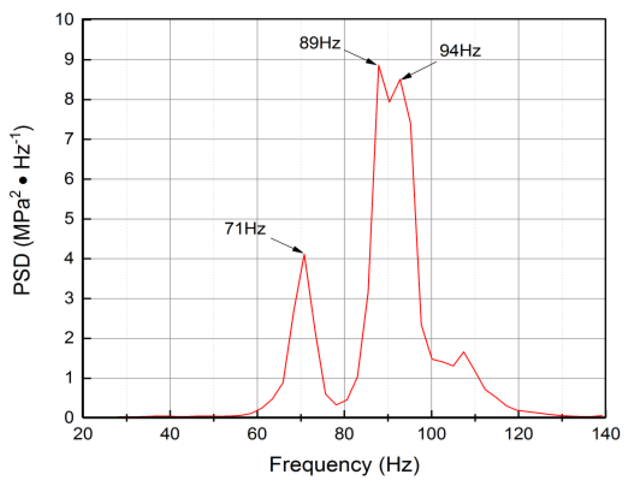
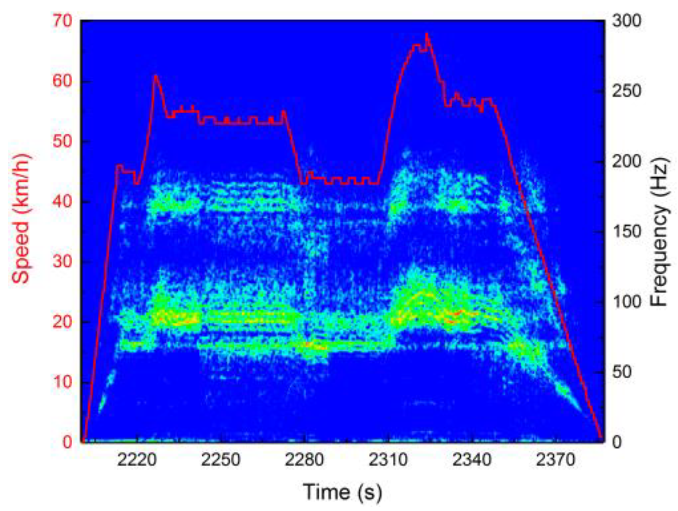
A typical stress time history signal of point D02 shown in Figure 8. The power spectral density (PSD) analysis and the speed-time-frequency relationship analysis of point D02 in some section are shown in Figure 9 and Figure 10, respectively. It could be observed that the dominant frequencies are 71 Hz, 89 Hz and 94 Hz and strongly relevant to the operating speeds. This demonstrates that these frequencies are not the structural natural frequencies and there is no obvious behavior of the resonate vibration.
2.2.2. Vibration Acceleration Test
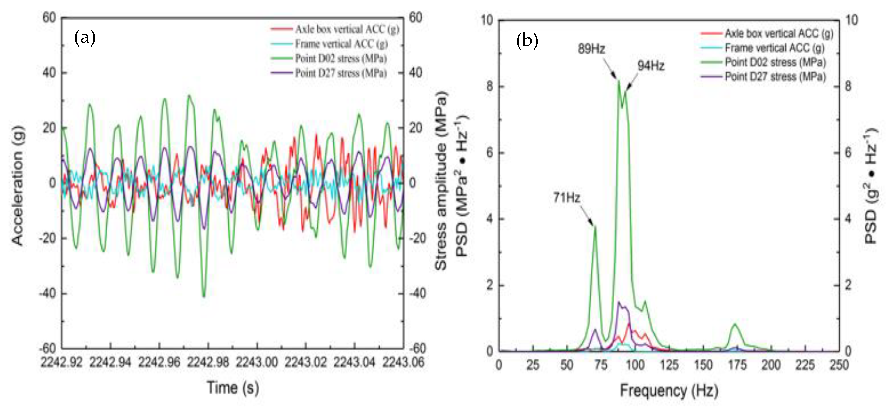
The intrinsic relationship between the vibration acceleration and stress response of the bogie frame was conducted by analyzing the dynamic stress response at D02/D27 and the vertical accelerations of the axle box and frame, shown in Figure 11. It can be concluded that: (1) the vertical accelerations of the frame and the axle box are coincident with frequency bands at 71 Hz, 89 Hz and 94 Hz. Moreover, they have a significant following behavior in the time domain; (2) dynamic stresses of Point D02 and D27 are highly coherent with the vibration acceleration of the axle box and frame in the time domain and frequency domain, and Point D02 has much higher stress amplitude and PSD value due to the positioning block local stress concentration. The dynamic stress and acceleration analysis clearly indicate that the dynamic stress response at D02/D27 has obvious main frequencies and consistent with the speed. Combined with the vibration acceleration test results, the following conclusion can be drawn that the dynamic stress response at the positioning block weld toe is directly caused by the vibration of frame, which mainly derives from the wheel-rail excitation.
3. Factors Relative to Crack Initiation and Propagation
3.1. Wheel Polygon
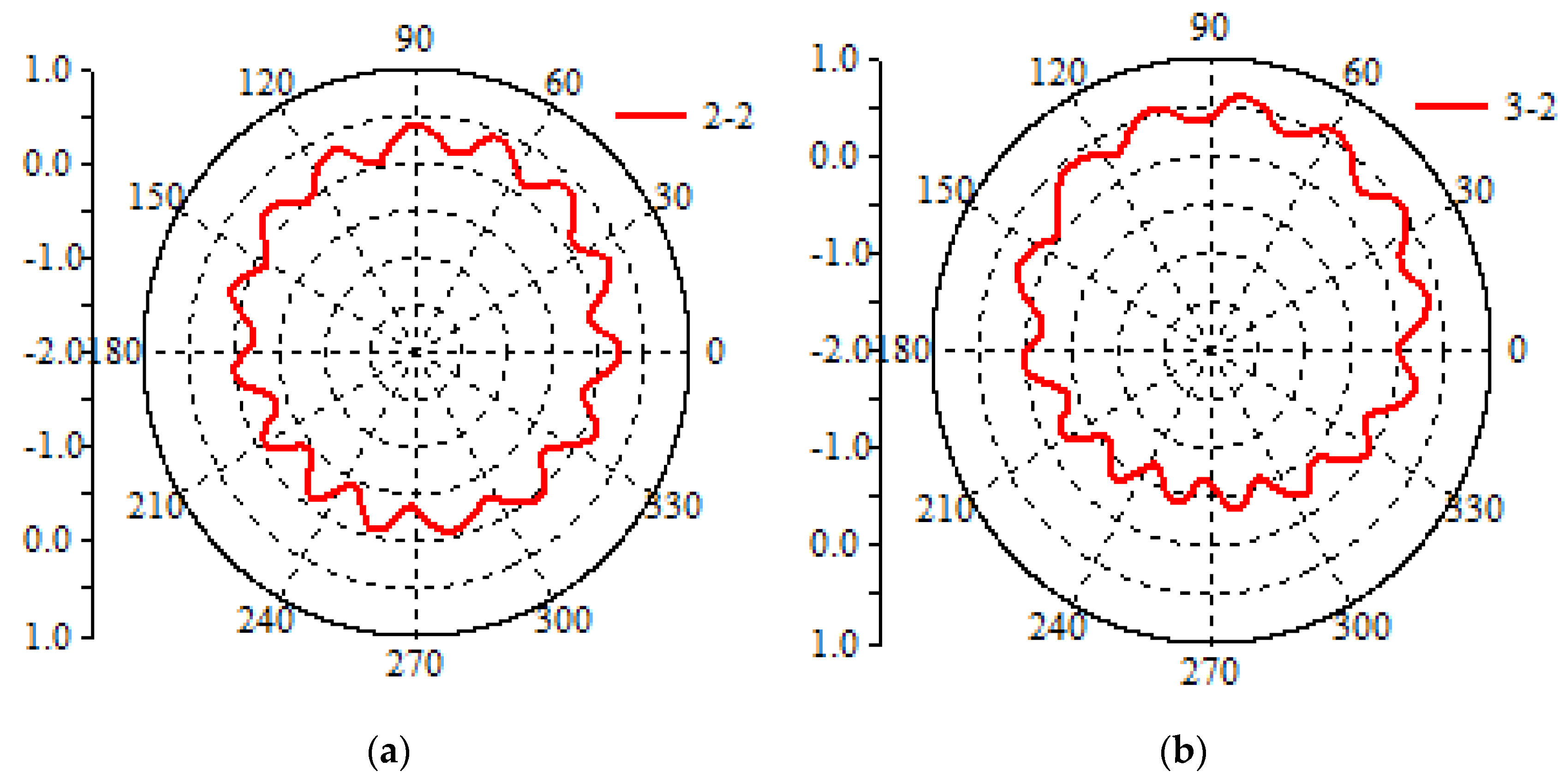
The roundness measurement results of No.1 and No.2 wheels installed on the tested bogie are shown in Figure 12a,b. No.1 wheel was a worn wheel after profiling, showing a good state. No.2 wheel was a worn wheel before profiling, demonstrating a significant polygonal worn phenomenon, with eccentric characteristics and 14- to 16-side polygon.
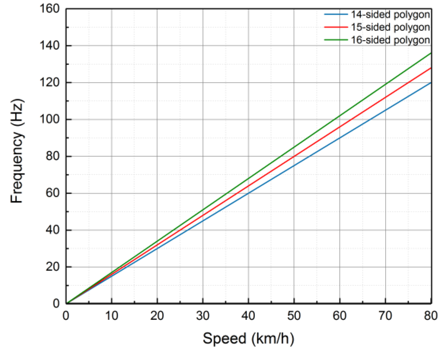
The wheel polygon will worsen the wheel-rail force and cause the high vibration of the axle box and bogie frame. The excitation frequencies of 14- to 16-side polygon wheel are coincided with the running speed linearly, shown in Figure 13. As indicated by the 15-sided wheel polygon analysis, for an example, when the operating speed is 54 km/h, the dominant frequency of the wheel-rail excitation is 86 Hz. Further, according to the analysis results of Figure 8 and Figure 10, it can be observed that the dominant frequency of the wheel-rail excitation (86 Hz) is similar to the dominant frequency (89 Hz) of dynamic stress amplitude at point D02 in 54 km/h.
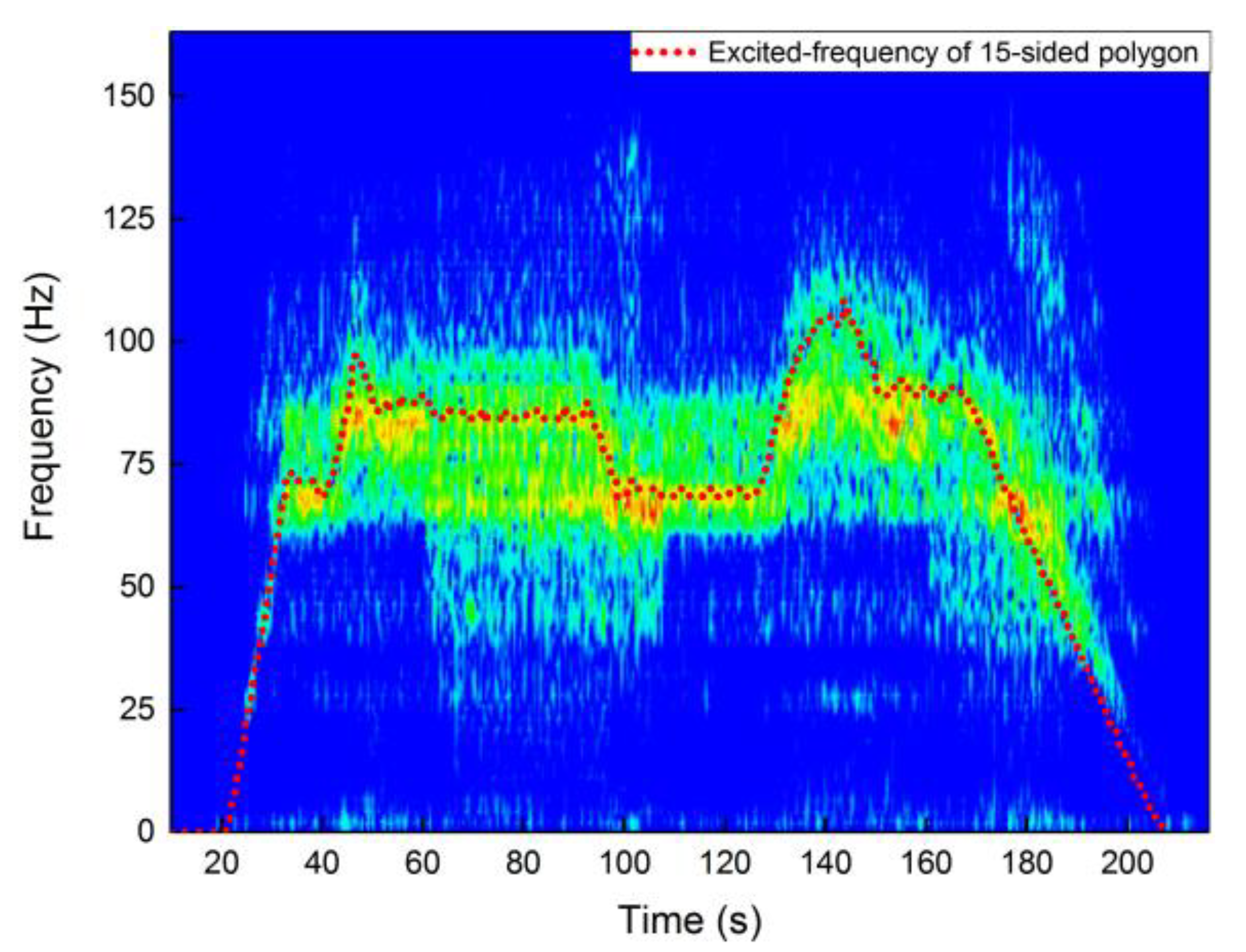
Figure 14 indicates the comparison results between the time-frequency diagram at point D11 and the frequency excited by the wheel polygon. It can be observed that the characteristic frequency of 15-sides polygon (red points in Figure 13) is highly consistent with the dominant frequency of dynamic stress.
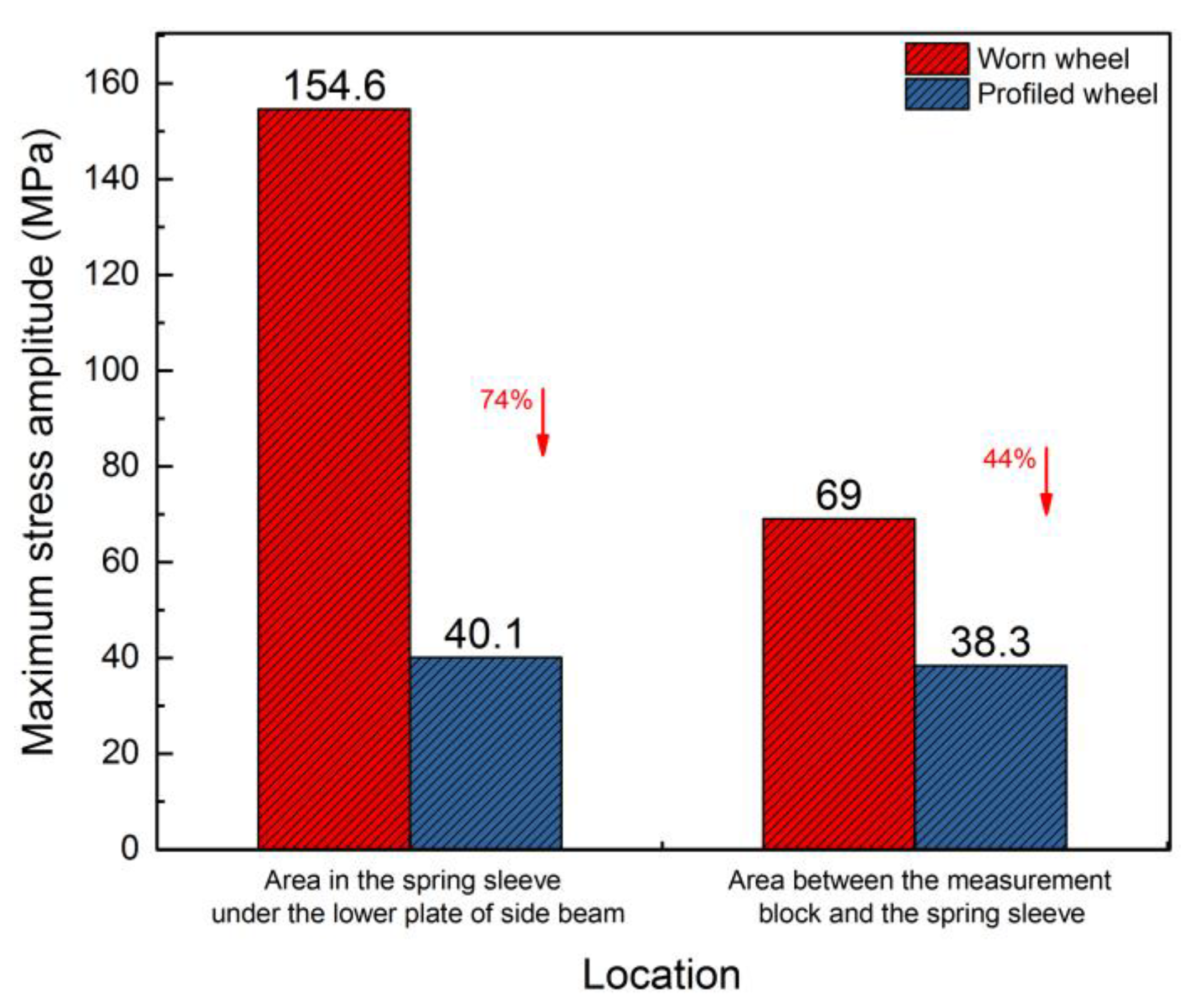
Figure 15 shows the comparison of the maximum dynamic stresses at D11 of the profiled and worn wheels. It can be observed that the maximum stress amplitude of the profiled wheel is significantly lower than that of the worn wheel, and the maximum reduction is 74%, indicating that the wheel polygon has a significant influence on the stress amplitude of the frame.
3.2. Rail Corrugation
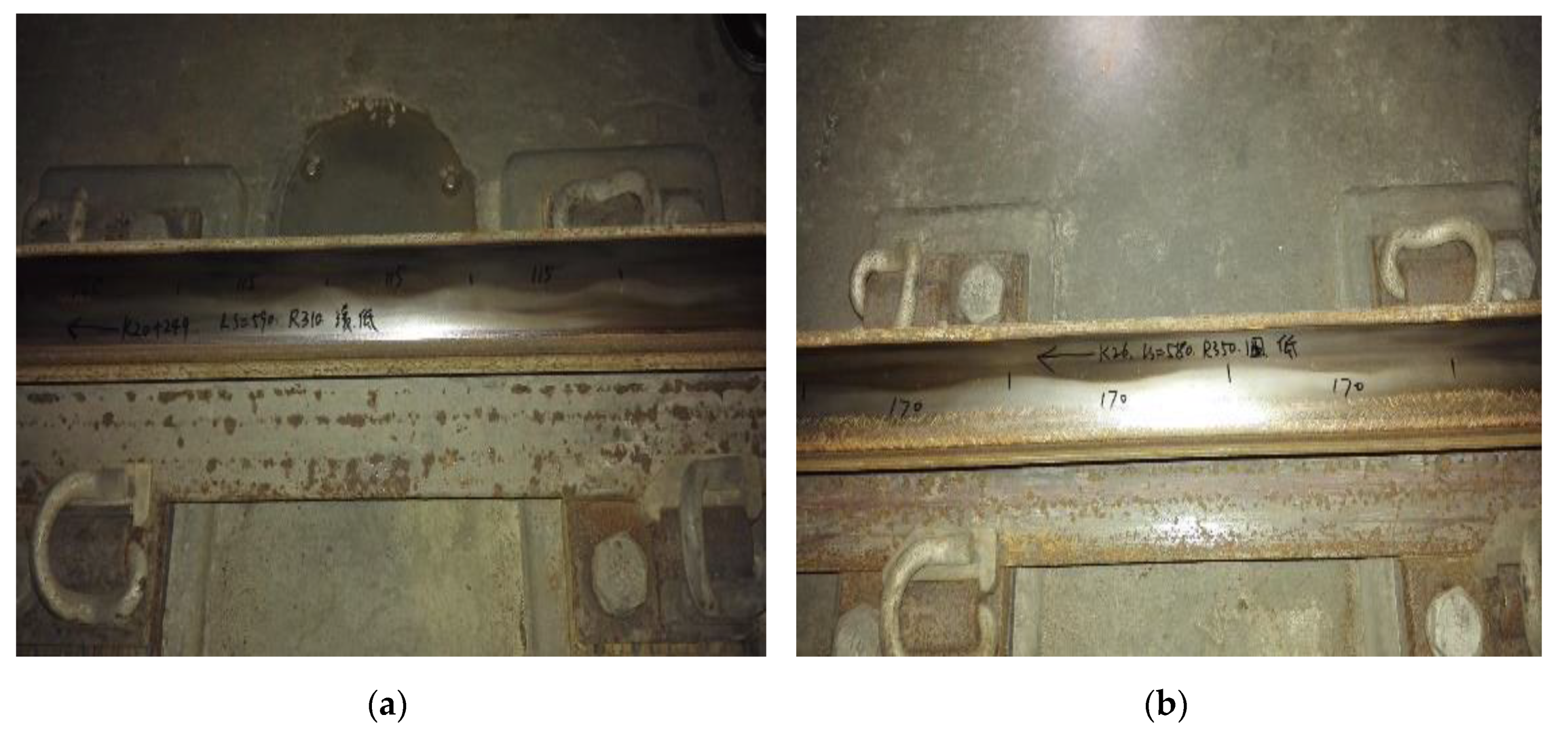
The investigation of the rail condition indicates that the different rail types show different corrugation characteristics, and the obvious rail corrugation area is mainly occurred on the curve with the radius below 600 m (denoted as R600). Figure 16 exhibits the rail corrugation diagrams in different sections, which indicates significant rail corrugation phenomena on the rail surface.
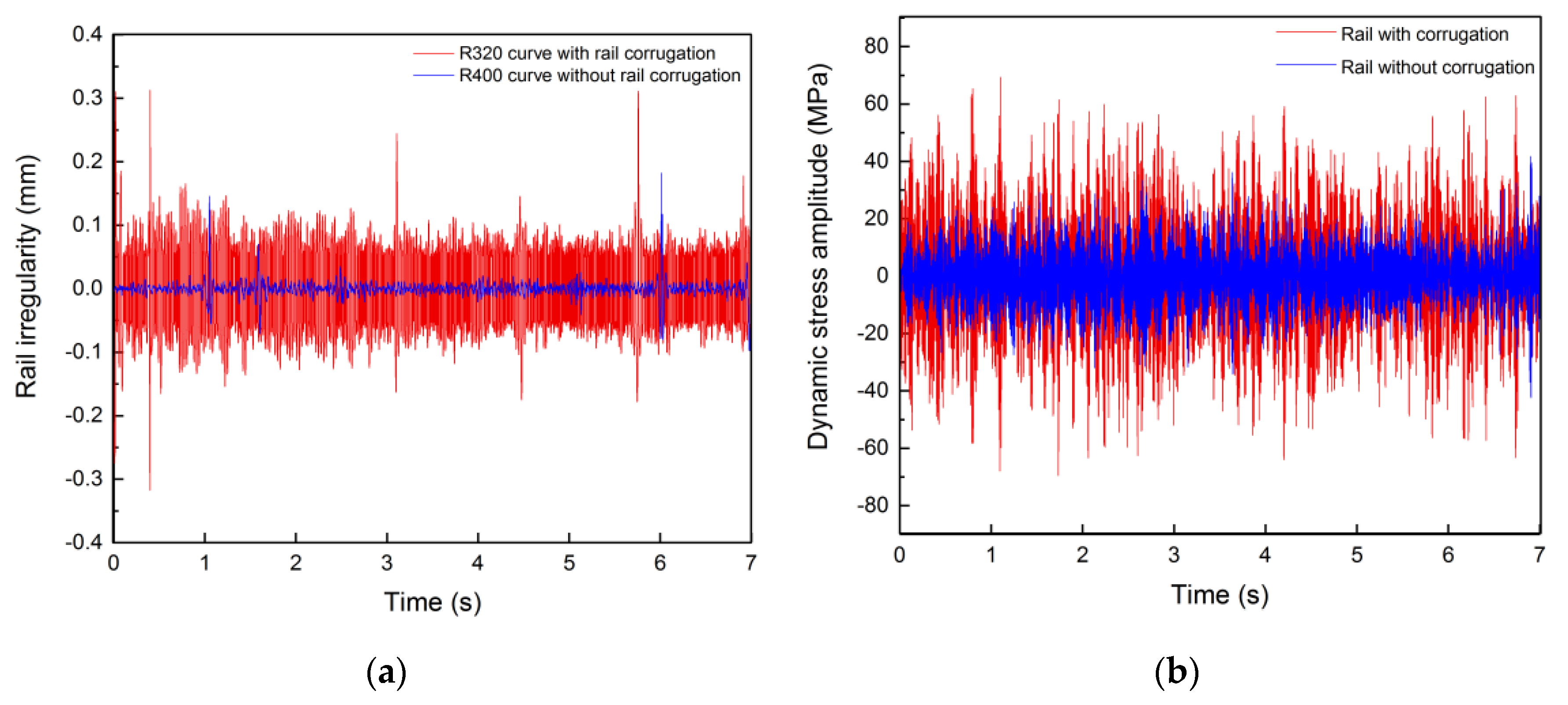
Figure 17 illustrates the comparison of the dynamic stress in the cracked area with and without rail corrugation, where R320 section exists corrugation phenomenon but R400 section does not exist. The operating speeds are both 54 km/h. It can be observed that in the corrugation section, the maximum rail irregularity is 0.31 mm, and the maximum dynamic stress is 72.8 MPa. While in the non-corrugation section, the maximum rail irregularity is 0.18 mm, and the maximum dynamic stress is 41.6 MPa. Obviously, the dynamic stress amplitude of the measurement point with rail corrugation increases by 75% than that without rail corrugation.
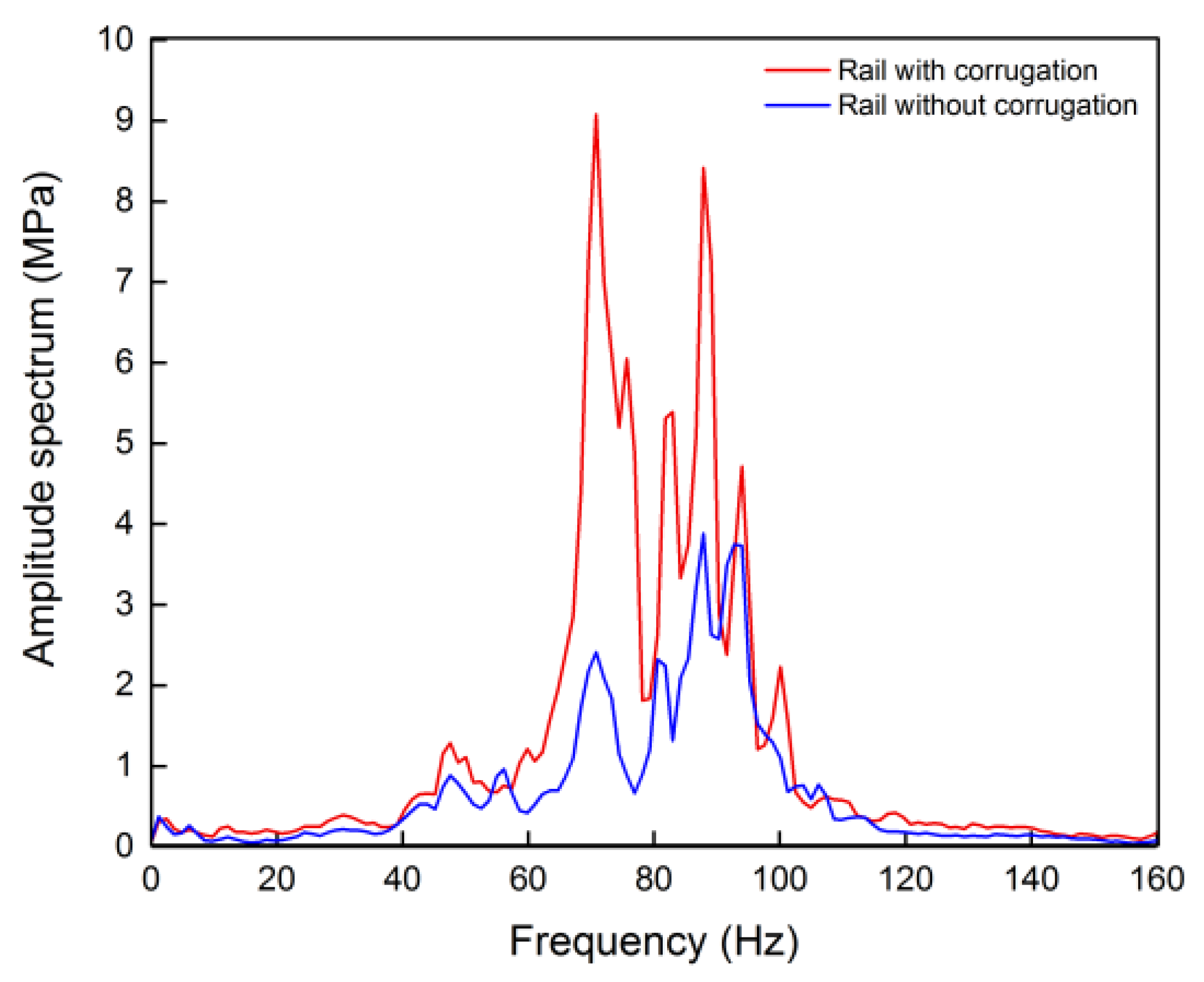
Meanwhile, Figure 18 shows a comparison of the characteristics of frequency domain with and without rail corrugation. It can be observed that in the frequency range of 60–90 Hz, the dynamic stress amplitude with rail corrugation is significantly greater than that without rail corrugation, especially in 71 Hz. In summary, the rail corrugation phenomenon has a significant effect on the dynamic stress amplitude at the cracked area.
3.3. Running Speed
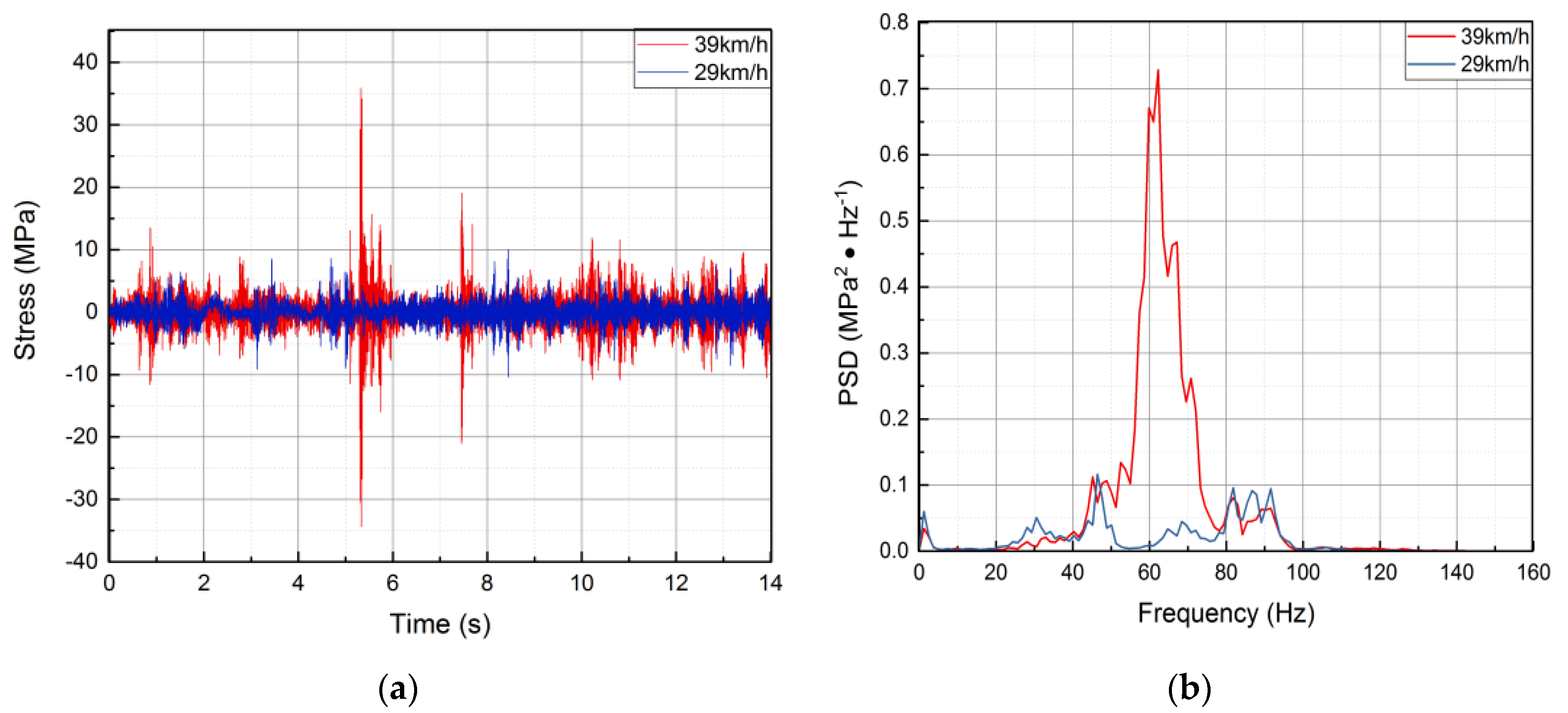
The wheel/rail vertical force increases with train running speed rising [17]. To investigate the relationship between the running speed and the dynamic stress amplitude, it is necessary to eliminate the influence of the rail condition. Therefore, a round-trip section was chosen to analyze. The round-trip speeds were 39 and 29 km/h, respectively, as shown in Figure 19. It can be observed that when the interval round-trip speeds were 29 and 39 km/h, respectively, the maximum values of dynamic stress amplitude were 10 and 36 MPa, and the main frequencies were 46 and 62 Hz. In conclusion, the amplitude and frequency of dynamic stress are significantly increased with the higher speed, which produces higher damage to the frame.
4. Conclusions
An extensive investigation of the fatigue crack development of positioning block welded to the spring sleeve in metro bogie frame was conducted. Systematic studies of fracture and metallographic analysis were employed to obtain failure modes and fracture characteristics of the weld toe of positioning block. On-track testing was carried out to obtain acceleration and stress response information of the bogie. After that, the test data analysis in the time domain and the frequency domain was conducted. The results are as follows:
(1) The weld toe of positioning block was the cracking initiation site, in which micro cracks were observed.
(2) The vibration frequency generated by the wheel polygon and the rail corrugation is highly coherent with the dominant frequency of dynamic stress at the cracked area, indicating that the wheel polygon and the rail corrugation have a significant effect on the dynamic stress amplitude. Further, the response of the amplitude and frequency of dynamic stress is higher with running speed increasing.
(3) The fractography and the on-track tests show that optimizing the weld technology, improving the weld quality, profiling the wheels, grinding the rails and decreasing the train running speed are all effective to reduce the failure probability and elongate the bogie frame life.
Author Contributions
Conceptualization, W.J.W.; formal analysis, W.J.W.; methodology, W.J.W.; project administration, P.Y.Z.; resources, W.J.W. and J.Z.; writing original draft, J.Y.B.; writing—review and editing, W.J.W. and S.C.W. All authors have read and agreed to the published version of the manuscript.
Funding
This research was funded by Beijing Nova Program Interdisciplinary Cooperation Project, grant number Z191100001119011, National Natural Science Foundation of China, grant number 11572267 and Major Systematic Project of CHINA RAILWAY, grant number P2018J003.
Conflicts of Interest
The authors declare no conflict of interest.
References
- Stanzl, S.E.; Tschegg, E.K.; Mayer, H.R. Lifetime measurements for random loading in the very high cycle fatigue range. Int. J. Fatigue 1986, 8, 195–200. [Google Scholar] [CrossRef]
- Yang, B.; Duan, H.; Wu, S.; Kang, G. Damage tolerance assessment of a brake unit bracket for high-speed railway welded bogie frames. Chin. J. Mech. Eng. 2019, 32, 58. [Google Scholar] [CrossRef] [Green Version]
- Guo, F.; Wu, S.C.; Liu, J.X.; Zhang, W.; Qin, Q.B.; Yao, Y. Fatigue life assessment of bogie frames in high-speed railway vehicles considering gear meshing. Int. J. Fatigue 2020, 132, 105353. [Google Scholar] [CrossRef]
- Kassner, M. Fatigue strength analysis of a welded railway vehicle structure by different methods. International journal of fatigue. Int. J. Fatigue 2012, 34, 103–111. [Google Scholar] [CrossRef]
- Wang, C.H.; Brown, M.W. Life prediction techniques for variable amplitude multiaxial fatigue—part 1: Theories. Int. J. Fatigue 1996, 118, 367–370. [Google Scholar] [CrossRef]
- Lu, Y.; Xiang, P.; Dong, P.; Zhang, X.; Zeng, J. Analysis of the effects of vibration modes on fatigue damage in high-speed train bogie frames. Eng. Fail. Anal. 2018, 89, 222–241. [Google Scholar] [CrossRef]
- Lučanin, V.J.; Simić, G.Ž.; Milković, D.D.; Ćuprić, N.L.; Golubović, S.D. Calculated and experimental analysis of cause of the appearance of cracks in the running bogie frame of diesel multiple units of Serbian railways. Eng. Fail. Anal. 2010, 17, 236–248. [Google Scholar]
- Zhang, C.Y.; Cheng, Y.J. Random vibration fatigue analysis of ATP antenna beam based on measured spectrum data. J. Dalian Jiaotong Univ. 2015, 36, 44–47. (in Chinese). [Google Scholar]
- Grassie, S.L. Rail corrugation: Characteristics, causes, and treatments. Proceedings of the Institution of Mechanical Engineers. Part F J. Rail Rapid Transit 2009, 223, 581–596. [Google Scholar] [CrossRef]
- Sato, Y.; Matsumoto, A.; Knothe, K. Review on rail corrugation studies. Wear 2002, 253, 130–139. [Google Scholar] [CrossRef]
- Zhang, H.; Liu, W.; Liu, W.; Wu, Z. Study on the cause and treatment of rail corrugation for Beijing metro. Wear 2014, 317, 120–128. [Google Scholar] [CrossRef]
- Ling, L.; Li, W.; Foo, E.; Wu, L.; Wen, Z.; Jin, X. Investigation into the vibration of metro bogies induced by rail corrugation. Chin. J. Mech. Eng. 2017, 30, 93–102. [Google Scholar] [CrossRef]
- Tassilly, E.; Vincent, N. A linear model for the corrugation of rails. J. Sound Vib. 1991, 150, 25–45. [Google Scholar] [CrossRef]
- Yan, Z.Q.; Gu, A.J.; Liu, W.N.; Markine, V.L.; Liang, Q.H. Effects of wheelset vibration on initiation and evolution of rail short-pitch corrugation. J. Cent. South Univ. 2012, 19, 2681–2688. [Google Scholar] [CrossRef]
- Meinke, P.; Meinke, S. Polygonalization of wheel treads caused by static and dynamic imbalances. J. Sound Vib. 1999, 227, 979–986. [Google Scholar] [CrossRef]
- Brommundt, E. A simple mechanism for the polygonalization of railway wheels by wear. Mech. Res. Commun. 1997, 24, 435–442. [Google Scholar] [CrossRef]
- Liu, X.; Zhai, W. Analysis of vertical dynamic wheel/rail interaction caused by polygonal wheels on high-speed trains. Wear 2014, 314, 282–290. [Google Scholar] [CrossRef]
- Peng, B.; Iwnicki, S.; Shackleton, P.; Crosbee, D.; Zhao, Y. The influence of wheelset flexibility on polygonal wear of locomotive wheels. Wear 2019, 432, 102917. [Google Scholar] [CrossRef]
- Cai, W.; Chi, M.; Tao, G.; Wu, X.; Wen, Z. Experimental and Numerical Investigation into Formation of Metro Wheel Polygonalization. Shock Vib. 2019, 2019, 1538273. [Google Scholar] [CrossRef]
- Fu, B.; Bruni, S.; Luo, S. Study on wheel polygonization of a metro vehicle based on polygonal wear simulation. Wear 2019, 438, 203071. [Google Scholar] [CrossRef] [Green Version]
- Wu, X.; Chi, M.; Gao, H. Damage tolerances of a railway axle in the presence of wheel polygonalizations. Engineering failure analysis. Eng. Fail. Anal. 2016, 66, 44–59. [Google Scholar] [CrossRef]
- Wu, X.; Rakheja, S.; Qu, S.; Wu, P.; Zeng, J.; Ahmed, A.K.W. Dynamic responses of a high-speed railway car due to wheel polygonalisation. Veh. Syst. Dyn. 2018, 56, 1817–1837. [Google Scholar] [CrossRef]
- Barke, D.W.; Chiu, W.K. A review of the effects of out-of-round wheels on track and vehicle components. Proc. Inst. Mech. Eng. Part F J. Rail Rapid Transit 2005, 219, 151–175. [Google Scholar] [CrossRef]
- Fu, D.; Wang, W.; Dong, L. Analysis on the fatigue cracks in the bogie frame. Eng. Fail. Anal. 2015, 58, 307–319. [Google Scholar] [CrossRef]
- Qin, G.D.; Liu, Z.M. Practical analysis method for fatigue life of welded frame of speed-up bogie. China Railw. Sci 2004, 25, 46. [Google Scholar]
- Dietz, S.; Netter, H.; Sachau, D. Fatigue life prediction of a railway bogie under dynamic loads through simulation. Veh. Syst. Dyn. 1998, 29, 385–402. [Google Scholar] [CrossRef]
- Kim, J.S. Fatigue assessment of tilting bogie frame for Korean tilting train: Analysis and static tests. Eng. Fail. Anal. 2006, 13, 1326–1337. [Google Scholar] [CrossRef]
Figure 1.
The crack position and the Macro morphology of the crack: (a) the crack position found in site; (b) the model of bogie frame and the positioning block; (c) and (d) the macro pictures of crack initiated from the weld toe of positioning block.
Figure 1.
The crack position and the Macro morphology of the crack: (a) the crack position found in site; (b) the model of bogie frame and the positioning block; (c) and (d) the macro pictures of crack initiated from the weld toe of positioning block.


Figure 2.
Micro-fracture morphology of the crack source and the fatigue striations: (a) 800×; (b) 3000×.
Figure 2.
Micro-fracture morphology of the crack source and the fatigue striations: (a) 800×; (b) 3000×.

Figure 3.
Microstructure of weld: (a) columnar grains enclosed by ferrite; (b) lamella ferrite and featherlike widmanstatten structure.
Figure 3.
Microstructure of weld: (a) columnar grains enclosed by ferrite; (b) lamella ferrite and featherlike widmanstatten structure.

Figure 4.
SEM of weld toe: (a) 50×; (b) 1600×.

Figure 5.
Strain gauge tested points around the positioning block: (a) D02; (b) D11 and D17; (c) D27.
Figure 5.
Strain gauge tested points around the positioning block: (a) D02; (b) D11 and D17; (c) D27.

Figure 6.
Vibration acceleration tested points: (a) sensor on the axle box; (b) sensor on the spring sleeve; (c) sensor on the motor.
Figure 6.
Vibration acceleration tested points: (a) sensor on the axle box; (b) sensor on the spring sleeve; (c) sensor on the motor.

Figure 7.
Full-range dynamic stress waveforms of D02, D11 and D17 (from top to bottom separately).

Figure 8.
The stress waveform at point D02.

Figure 9.
The power spectrum diagram at point D02.

Figure 10.
The speed-time-frequency relationship diagram at point D02.

Figure 11.
Relationship between the vibration acceleration and stress response: (a) time domain diagram; (b) power spectrum diagram.
Figure 11.
Relationship between the vibration acceleration and stress response: (a) time domain diagram; (b) power spectrum diagram.

Figure 12.
Polar diagram of roundness: (a) No.1 wheel; (b) No.2 wheel.

Figure 13.
Relationship between wheel polygon and running speed.

Figure 14.
The frequency comparison between dynamic stress at point D11 and excitation from the wheel polygon phenomenon.
Figure 14.
The frequency comparison between dynamic stress at point D11 and excitation from the wheel polygon phenomenon.

Figure 15.
The comparison of the maximum stress amplitude of the profiled and worn wheels around the cracked area.
Figure 15.
The comparison of the maximum stress amplitude of the profiled and worn wheels around the cracked area.

Figure 16.
Rail corrugation in different sections: (a) section 1; (b) section 2.

Figure 17.
The relationship between rail irregularity and the dynamic stress amplitude: (a) degree of rail irregularity; (b) dynamic stress.
Figure 17.
The relationship between rail irregularity and the dynamic stress amplitude: (a) degree of rail irregularity; (b) dynamic stress.

Figure 18.
The amplitude spectrum comparison of the dynamic stress of the frame with and without the rail corrugation.
Figure 18.
The amplitude spectrum comparison of the dynamic stress of the frame with and without the rail corrugation.

Figure 19.
Round-trip time-frequency domain stress diagrams at different speeds: (a) time domain diagram; (b) time-frequency diagram.
Figure 19.
Round-trip time-frequency domain stress diagrams at different speeds: (a) time domain diagram; (b) time-frequency diagram.


Table 1.
Testing conditions for dynamic stress and vibration acceleration.
| No. | Test Conditions | Descriptions | Test Mileage/km |
|---|---|---|---|
| 1 | Normal operation | Bogie for normal operation | 141.1 |
| 2 | Normal operation | Bogie with profiled wheel | 124 |
| 3 | Interval speed limit operation | Bogie for normal operation | 109 |
© 2020 by the authors. Licensee MDPI, Basel, Switzerland. This article is an open access article distributed under the terms and conditions of the Creative Commons Attribution (CC BY) license (http://creativecommons.org/licenses/by/4.0/).
Share and Cite
MDPI and ACS Style
Wang, W.; Bai, J.; Wu, S.; Zheng, J.; Zhou, P. Experimental Investigations on the Effects of Fatigue Crack in Urban Metro Welded Bogie Frame. Appl. Sci. 2020, 10, 1537. https://doi.org/10.3390/app10041537
AMA Style
Wang W, Bai J, Wu S, Zheng J, Zhou P. Experimental Investigations on the Effects of Fatigue Crack in Urban Metro Welded Bogie Frame. Applied Sciences. 2020; 10(4):1537. https://doi.org/10.3390/app10041537
Chicago/Turabian StyleWang, Wenjing, Jinyi Bai, Shengchuan Wu, Jing Zheng, and Pingyu Zhou. 2020. "Experimental Investigations on the Effects of Fatigue Crack in Urban Metro Welded Bogie Frame" Applied Sciences 10, no. 4: 1537. https://doi.org/10.3390/app10041537
Note that from the first issue of 2016, this journal uses article numbers instead of page numbers. See further details here.