Damage Investigation of Carbon-Fiber-Reinforced Plastic Laminates with Fasteners Subjected to Lightning Current Components C and D

1
Key Laboratory of Control of Power Transmission and Conversion, Ministry of Education, Shanghai Jiao Tong University, Shanghai 200240, China
2
State Key Laboratory of Safety and Control for Chemicals, Qingdao Safety Engineering Institute, SINOPEC, Qingdao 266000, China
*
Author to whom correspondence should be addressed.
Appl. Sci. 2020, 10(6), 2147; https://doi.org/10.3390/app10062147
Submission received: 24 February 2020
/
Revised: 14 March 2020
/
Accepted: 19 March 2020
/
Published: 21 March 2020
(This article belongs to the Special Issue Recent Advances in Theoretical and Computational Modeling of Composite Materials and Structures)
Abstract
:The damage induced by lightning strikes in carbon-fiber-reinforced plastic (CFRP) laminates with fasteners is a complex multiphysics coupling process. To clarify the effects of different lightning current components on the induced damage, components C and D were used in simulated lightning strike tests. Ultrasonic C-scans and stereomicroscopy were used to evaluate the damage in the tested specimens. In addition, the electrothermal coupling theory was adopted to model the different effects of the arc and the current flowing through the laminate (hereinafter referred to as the conduction current) on CFRP laminates with fasteners under different lightning current components. Component C, which has a low current amplitude and a long duration, ablated and gasified the fastener and caused less damage to the CFRP laminate. Under component C, the heat produced by the arc played a leading role in damage generation. Component D, which has a high current amplitude and a short duration, caused serious surface and internal damage in the CFRP laminate and little damage to the fastener. Under component D, the damage was mainly caused by the Joule heat generated by the conduction current.
1. Introduction
Carbon-fiber-reinforced plastics (CFRPs) have excellent mechanical properties and are widely used in various industries [1,2,3]. With the massive expansion of wind power and the rapid growth in the number of aircraft, the chances of wind turbine blades and aircraft being struck by lightning have inevitably increased substantially. Because the destructive effects of lightning strikes often lead to serious consequences, research on lightning damage in CFRPs has received unprecedented attention [4,5,6,7,8].
In structural design, depending on the excellent formability of composite materials, the number of fasteners can be reduced by optimizing the design; however, completely eliminating the need for fasteners is difficult. These fasteners have greater electrical conductivity than the other materials in CFRP laminates. Therefore, when a lightning strike occurs, the current is discharged through the fasteners first and then into each layer of the CFRP laminate, which leads to fiber breakage, resin degradation, and internal delamination [9]. In addition, the temperature and air pressure inside the fastener hole will change dramatically during the lightning strike [10], which leads to damage around the hole, loss of fastener support, and weakening of the mechanical and electrical properties of the CFRP [11]. Therefore, research on the damage in CFRPs with fasteners subjected to lightning strikes is the key point of composite lightning protection [10,12].
The duration of a lightning strike is extremely short, during which a large amount of energy is released in an instant, resulting in extremely high temperatures. Observing the damage characteristics near the attachment point of the lightning strike in real time with instruments is difficult. Therefore, finite element analysis (FEA) has become an effective method for studying the damage evolution process of CFRP laminates with fasteners under lightning strikes and for verifying the correctness of the test results. Chemartin et al. [13] used the finite volume method in the time domain and unstructured mesh to establish the mechanism model of CFRPs with fasteners, and simulated the spark phenomenon in fasteners. The research showed that sparking may occur when the current density is greater than 10 kA/mm2. Kirchdoerfer [10] simulated the gas conditions and related local geometric changes in the interior space around the fastener during lightning strikes, and discussed the importance of chemical change modeling in future work. Meanwhile, the electrothermal coupling model is used to investigate the damage of CFRP under lightning strike. Muñoz et al. [14] developed a finite element model to consider the damage sources observed in a lightning strike, such as thermal damage caused by Joule heat. Yin et al. [11] established a three-dimensional electrothermal coupling model of ablation damage of CFRP with fasteners based on the relationship of the energy balance in s lightning strike. The results indicated that fasteners distributed the lightning current to each layer, and a larger conduction current dispersion area led to less damage to the laminate. Abdelal et al. [15] proposed a physical model to predict lightning strike damage for composite materials. The finite element method of non-linear material model was used to analyze composite materials with copper mesh protection. Ogasawara et al. [16] proposed a electrothermal coupling model of angle ply composite laminates, which considered the anisotropic thermoelectric behavior of layer and unidirectional composite laminates. However, their work neglected the arc heat effect in numerical simulation. Dong et al. [17] considered the influence of the arc heat effect and replaced it with heat flux in the models, while the damage to CFRP with fasteners was not mentioned. On the basis of previous work, this paper used the electrothermal coupling module in COMSOL to design simulation models to explore the arc heat and conduction current effects on the damage of CFRP with fasteners, as well as the damage difference under different lightning current conditions.
Experimental investigations are often used to study the damage in CFRP laminates with fasteners subjected to lightning strikes. Previous studies have found a relationship between the damaged area and the mounting depth of the fasteners during a lightning strike. The shallower the mounting depth, the larger the surface damage area [18]. CFRP laminates with fasteners show penetrating damage under lightning strikes, with damage occurring on both sides of the specimen [19,20]. The lightning current component D is influential in developing out-gassing, whereas no out-gassing is observed when component C is used [21]. To make the simulated lightning strikes in the laboratory more closely approximate natural lightning strikes, it is important to ensure that the lightning current waveforms and current amplitudes used in the tests meet the standard requirements [19]. However, in the study of lightning damage in CFRP laminates with fasteners, many of the waveforms and amplitudes used in previous studies did not meet the standard requirements [22,23], and the roles of the arc and conduction current in the process of damage were not clearly distinguished.
In this work, simulated lightning strike tests were performed on CFRP laminates with fasteners using lightning current components C and D, which comply with the standards. Ultrasonic C-scans and stereomicroscopy were used to evaluate the differences in specimen damage under the two components, and an electrothermal coupling model was adopted to verify the test results to study the different effects of the conduction current and arc after the action of lightning current components C and D. The results were compared with the lightning damage of pure CFRP under components C and D [17].
2. Materials and Methods
2.1. Specimen Preparation
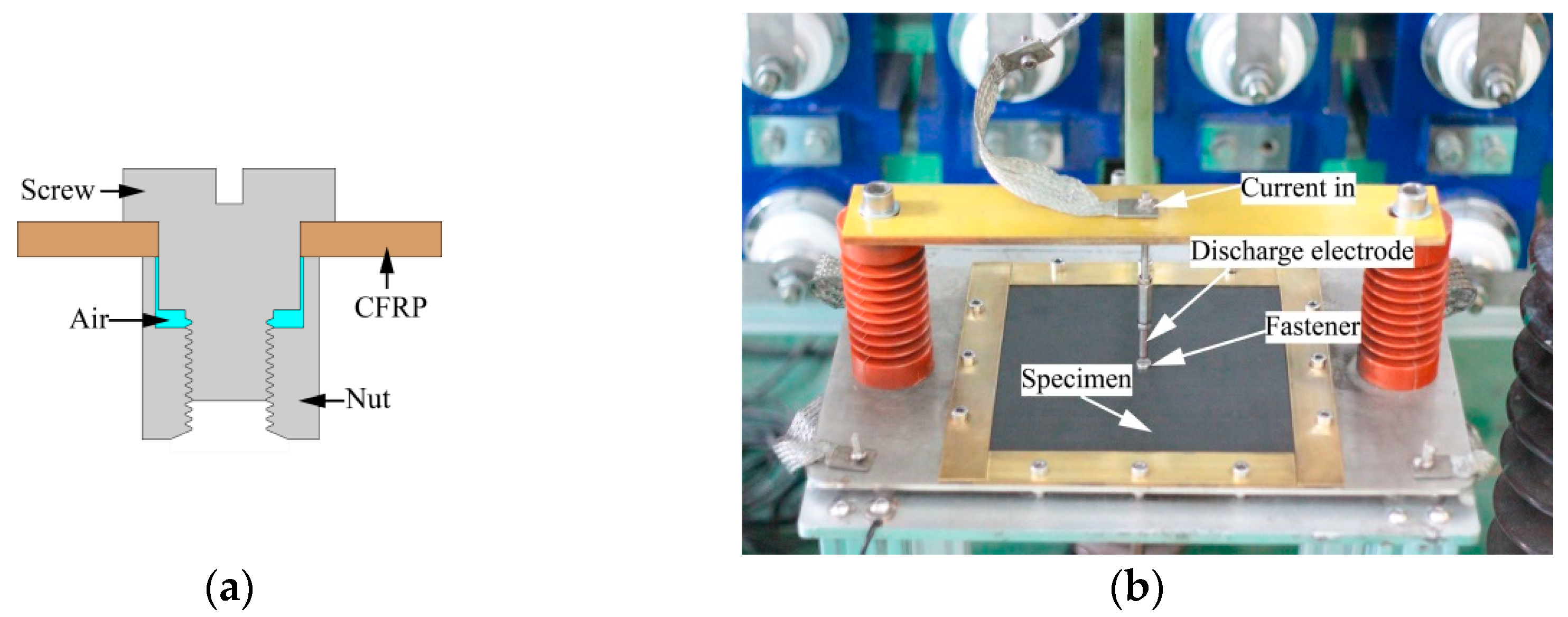
The material used in this work was a unidirectional carbon fiber prepreg (TC35/FRD-Y360). The specimen dimensions were 250 mm (length) × 250 mm (width) × 2 mm (thickness), and the stacking sequence was , creating a total of 15 plies. The diameter of the mounting hole was 8 mm, and the fastener material was stainless steel. Compared with titanium alloy, stainless steel has good electrical conductivity and a lower melting point, which will result in more severe damage during lightning strikes, which is beneficial for observation and analysis. The specimens used in this work were unpainted and unprotected. This structure allowed us to focus on the details of CFRP response to high energy discharge alone [19]. The assembly of the fastener and CFRP laminate is shown in Figure 1a. The tight fitting of the fastener and the CFRP laminate mounting hole can reduce the contact resistance between the two elements. The discharge electrode with a diameter of 8 mm was made of tungsten–copper alloy (W80Cu20) and was positioned directly above the centre point of the specimen, separated from the specimen by a distance of approximately 3 mm. The four sides of the specimen were fixed on a metal plate with detachable copper strips. For reliable grounding, four copper braids were connected at the four corners of the metal plate. The simulated lightning current was injected into the specimen as an arc discharge and then flowed through the metal plate and out through the copper braid. The clamp and connection are shown in Figure 1b.
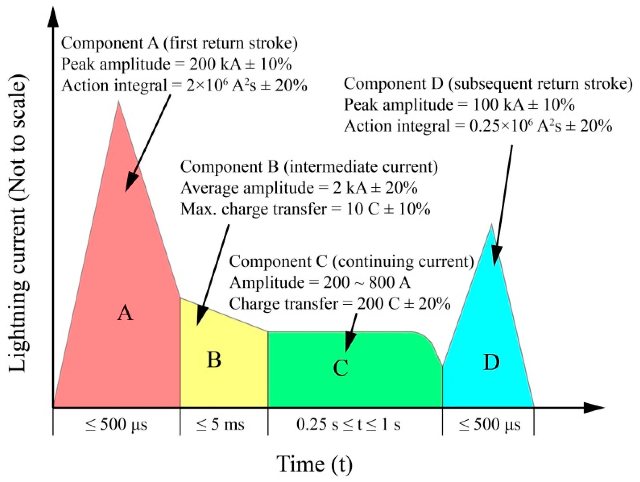
2.2. Test setup and waveform
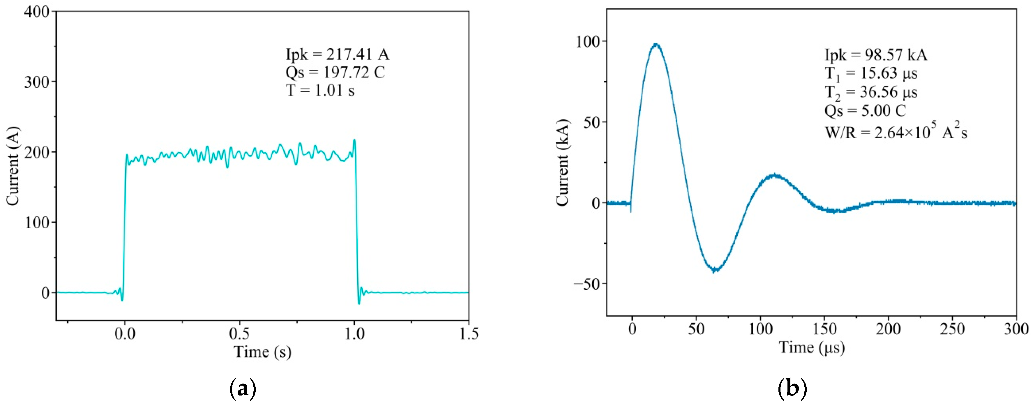
The lightning current waveforms described in [22] and [23] include four components (Figure 2). Components A, B, C, and D represent the first return stroke, intermediate current, continuing current, and the subsequent return stroke, respectively. These four components can be divided into two categories: (1) short-duration, small-transferred-charge, high-action-integral, high-current-amplitude components A and D; and (2) long-duration, large-transferred-charge, low-action-integral, low-current-amplitude components B and C. To make this study universal, lightning current components C and D were used in the simulated lightning strike test of the CFRP laminates with fasteners. The current amplitude of component C was 200 A, the duration of which could reach 1 s, and the transferred charge was 200 C; the actual test waveform is shown in Figure 3a. The current amplitude of component D was 100 kA, the duration could reach 500 µs, and the action integral was 2.5 × 10⁵ A2s; the actual test waveform is shown in Figure 3b.
3. FEA
3.1. Electrothermal Coupling Theory
Because of the short duration of the lightning strike, measuring and observing the damage evolution process is difficult. Therefore, FEA is an effective method for analyzing the process. COMSOL was successfully applied to the finite element simulation of CFRP damage during lightning strikes [10]. The electrothermal coupling module in COMSOL provides a method for analyzing such problems. The module considers both the effect of the electrical conductivity with respect to temperature and the effect of the electric field with respect to the current density.
Herein, a steady-state electrical simulation analysis and a transient thermal simulation analysis are performed in sequence [24]. The lightning current flowing through the CFRP laminate will generate Joule heat, causing the resin to pyrolyze and gasify, which is a typical electrothermal coupling process [25,26,27]. During this process, the following charge conservation equations need to be followed:
where is the charge density and is the current density inside the material.
The relationship between the current and Joule heat can be expressed as follows:
where is Joule heat per unit volume and and E are the electric conductivity and electric field intensity per unit volume, respectively.
The heat transfer in the material conforms to Fourier’s law. The governing equation of heat balance can be expressed as follows [14,27,28]:
where is the specific heat capacity at constant pressure, is the density, is the absolute temperature, and is the thermal conductivity.
The heat transferred to the material by the arc is equivalent to the heat flux [17], and the heat flux is expressed as follows:
where is the time, is the heat flux of the lightning arc, and J is the current density on the top of the fastener.
3.2. Finite Element Modeling
During the lightning strike, the temperature changes drastically, and the thermal conductivity, electrical conductivity, density, and specific heat of the material change significantly with respect to the temperature [15,29,30]. Table 1 shows the material parameters measured by thermogravimetric analysis (NETZSCH STA449F3, Germany) and laser flash thermal conductivity analysis (LFA467, Germany).
The parameters of stainless steel fasteners are shown in Table 2.
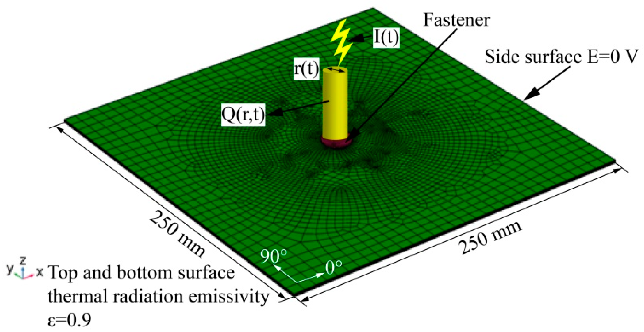
Some assumptions were proposed: no clearance between fastener and composite, and the contact electrical resistance and thermal resistance on the interface were ignored; the delamination caused by Joule heat and the thermal stress inside the specimen was not considered. The stacking sequences and dimensions of the CFRP laminate used in the finite element modeling were the same as those of the specimen. The model is shown in Figure 4. The whole model had 28,157 elements, 28,055 hexahedra, 2,200 edge elements, and 136 vertex elements. The electrical potential boundary of the model was set as follows: the electrical potential of the two parallel sides was 0 V. Heat exchange between the specimen and the environment occurred when the specimen was directly exposed to the air. Therefore, the thermal boundary of the model was set as follows: the thermal radiation emissivity of the top and bottom surfaces was 0.9; the four sides of the model were thermally insulated and did not exchange heat with the external environment; and the environmental temperature was 25 °C. The conduction current and heat flux of components D and C were imported into COMSOL and applied on the entire top surface of the fastener. For modeling of different fiber orientations, rotated coordinate systems were used and the material properties of CFRP were assigned to each layer. For each layer, the size of elements increased from the center to the four sides to improve the efficiency and ensure the accuracy at the same time. The maximum and minimum side lengths were 10 mm and 3 mm, respectively. The average element quality was about 0.9. The total time of the transient solver was set according to the duration of the waveform (300 µs for component D and 1 s for component C). In this work, the relative tolerance of the simulation model was 0.01, the tolerance factor was 0.1, the maximum number of iterations was 10, and the termination technique was the tolerance. The simulation was done on a Dell Precision Tower 780 workstation equipped with two E5-2603 CPUs and 48 GB memory, and the longest time consumed about 11 h for a calculation case. In the process of calculation, the temperature distribution and the physical parameters of the materials were monitored by the domain point probes arranged in the model to ensure the convergence of the model.
In the model, is the arc channel radius; is the heat flux obtained by Equation (4), which is used to represent the role of the arc; and is the conduction current injected into the top of the fastener.
The heat flux radius is assumed to be the same as the fastener radius. When a lightning strike occurs, the lightning current is divided into two parts: one part is attached to the top of the fastener in the form of an arc, whereas the other part is conducted in the fastener and the laminate in the form of conduction current. Therefore, the damage in CFRP laminates with fasteners is caused by the combination of the arc and conduction current. To understand the effect of the arc and conduction current on CFRP damage and to understand the difference in CFRP damage under different lightning current components, we designed three simulation models for each lightning current component, as shown in Table 3.
4. Results
4.1. Surface Damage
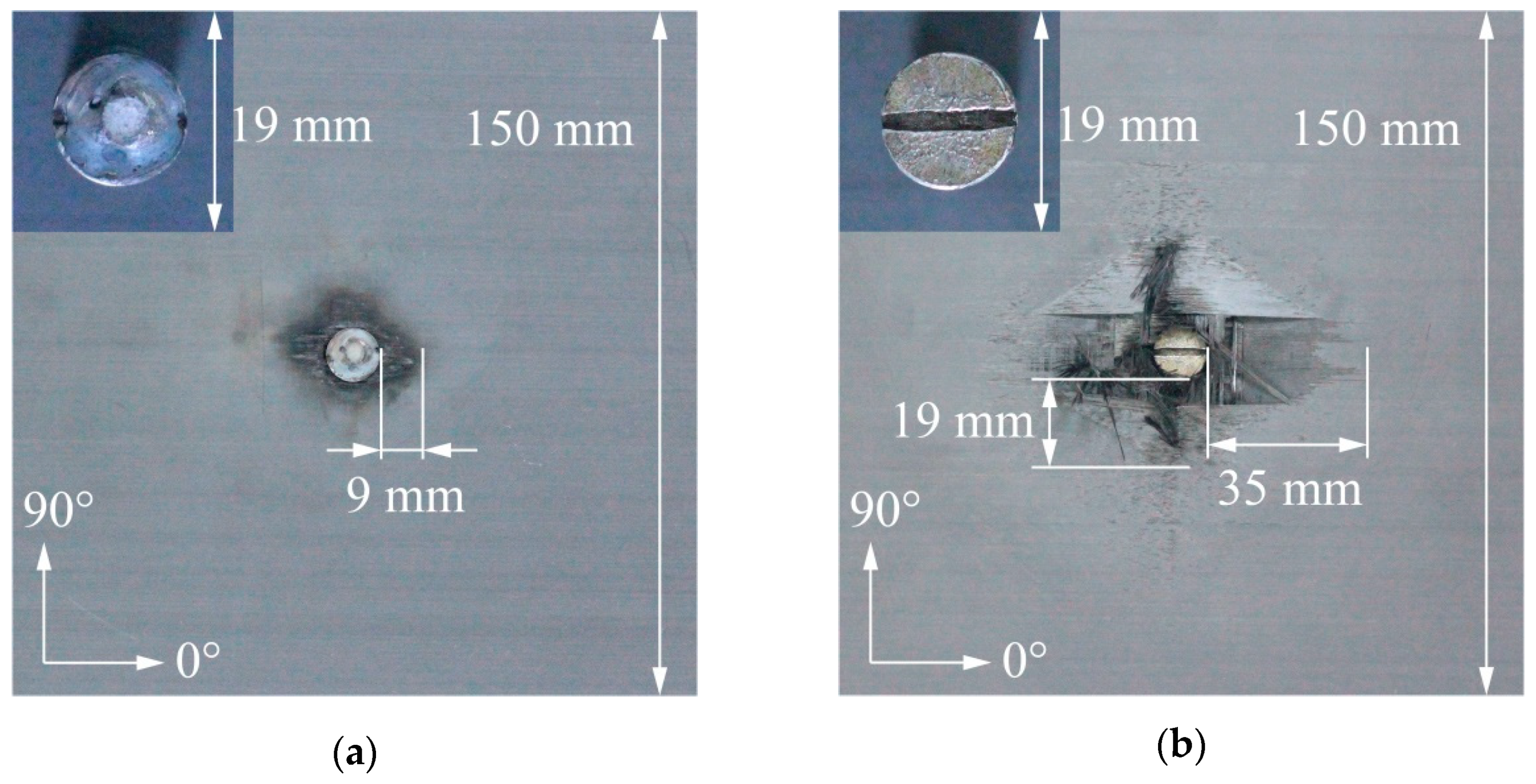
Figure 5a,b show the surface damage in the specimens under the action of components C and D, respectively.
For component C, serious ablation damage occurred on the top of the fastener, which was still tightly connected to the laminate. The damage in the laminate was located within a distance of 9 mm around the fastener. Resin discoloration was observed but very few fibers were exposed or warped.
For component D, no obvious damage was observed on the top of the fastener, but the fastener was loose and slightly sunken. Fiber tufts, fiber breakage, resin sublimation, and resin discoloration appeared on the surface of the laminate. These forms of damage extended 35 mm along the fiber direction and 19 mm orthogonal to the fiber direction. In addition, flaky fiber shedding was observed along the fiber direction.
4.2. Damage in the Fastener Hole
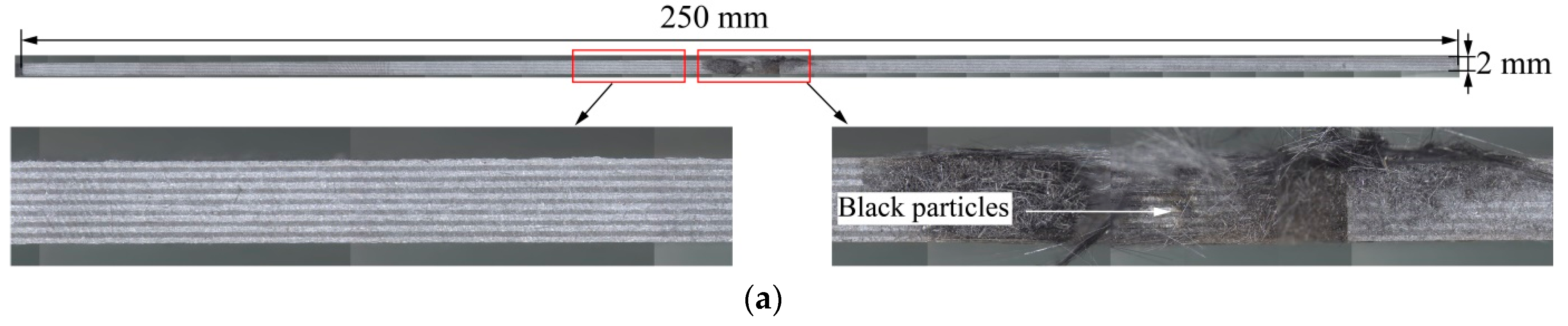
After the lightning strike tests, each specimen was cut, as shown in Figure 6c, and the cross-section of the hole was observed with a stereomicroscope (Leica/M125, Germany). Figure 6a,b are cross-sectional photos of the specimen after the action of components C and D, respectively. In these figures, the regularly spaced vertical lines are the shadows left by the synthesis of multiple cross-sectional photos, which do not represent the damage.
For component C, black particles cover the surface of the inner wall of the fastener hole and few fiber breakages or cracks are observed between the layers, which indicates that the temperature of the inner wall of the hole was not high when the specimen was subjected to a lightning strike and that the amount of resin vaporized by the lightning strike was not substantial.
For component D, Figure 6b shows extended delamination damage away from the hole. Resin matrix cracks and fiber breakages are observed around the hole, and black particles also appear in the hole. As the fastener penetrated the laminate, the delamination damage near the hole became extremely serious.
4.3. Internal Damage
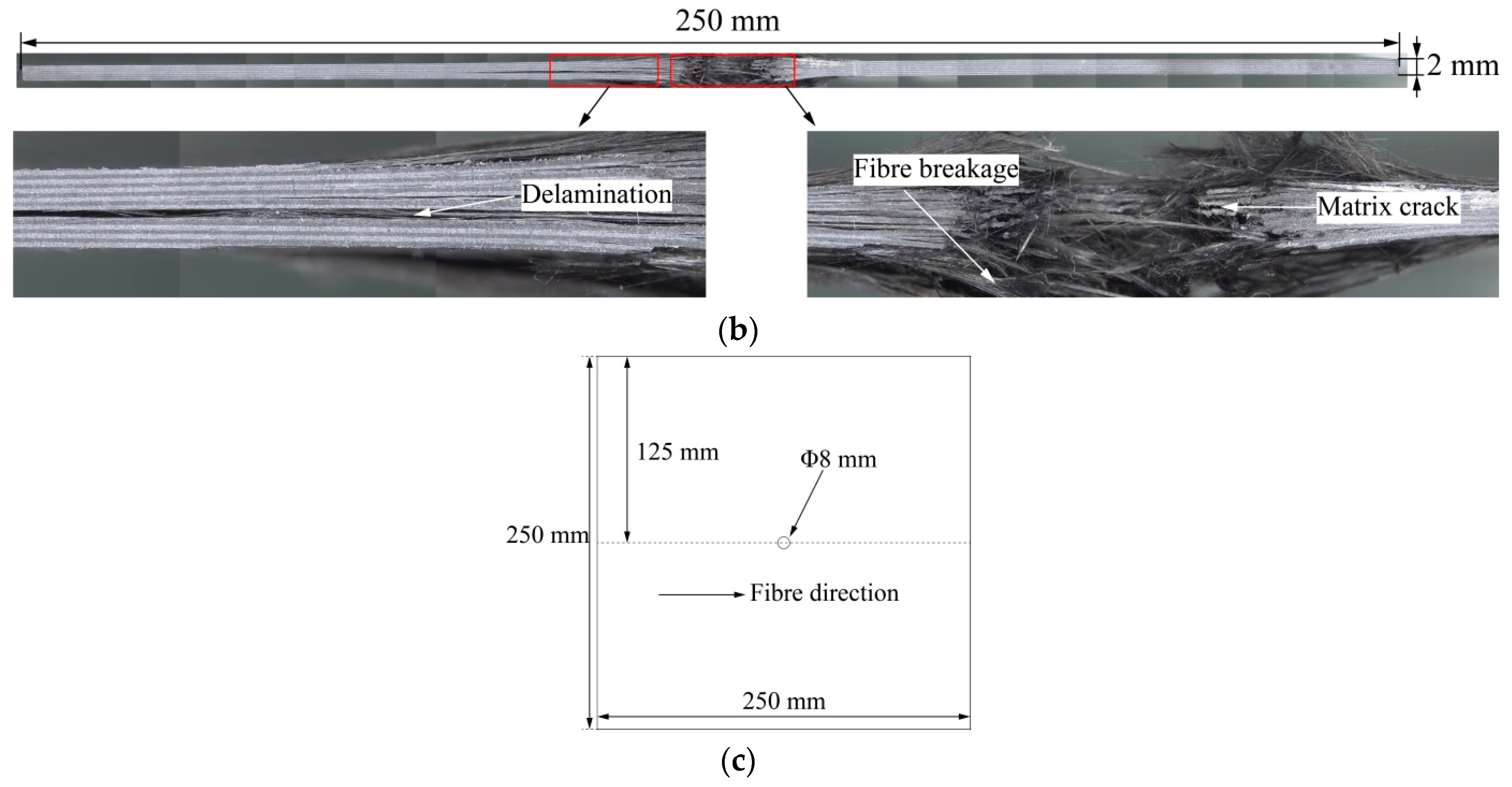
The internal damage in the CFRP laminate can be non-destructively evaluated with an ultrasonic scanning device (KSI V400E, Germany). The frequency of the ultrasonic wave was 40MHz, and the pulse–echo mode was used for scanning. Ultrasound C-scan, which is sensitive to delamination, is based on the reflection of ultrasonic energy from the intermediate interface. When the ultrasonic wave encounters the damaged interface, the reflected energy in the form of pulse–echo amplitude is different from the undamaged condition [33]. The reflected ultrasonic signals are converted into image signals with different gray values.
Figure 7a,b show the internal damage morphology under the action of components C and D, respectively. These figures show that the damage expands from the fastener to the delamination boundary after the lightning strikes. The damage within the delamination boundary in Figure 7 consists of two zones. One is the thermal decomposition damage and ablation damage, where the material is pyrolyzed and vaporized (marked with dark red, hereinafter referred to as the decomposition damage). The other is speculated to be delamination (marked with blue), where the damage of the interlayer structure is caused by the internal pressure generated by the rapid expansion of pyrolysis gas [34].
For component C, the damage area inside the specimen is small, the damage lengths in the 0° direction and 90° directions are approximately 30 mm, and the difference between the two directions is small (in Figure 7a, the damage length in the 0° direction is 30.4 mm, whereas the damage length in the 90° direction is 29.8 mm). This finding indicates that a small amount of resin in the specimen has undergone pyrolysis and gasification during the lightning strike.
For component D, a large area of damage is observed in the specimen, and the damage lengths in the 0° and 90° directions are greater than 100 mm, which indicates that during the lightning strike, component D induces more resin pyrolysis and gasification than component C. Moreover, an internal explosion occurs under component D. The rhomboid-shaped damage area might be caused by the orthogonal stacking structure of the specimen.
4.4. Finite Element Simulation Results
During a lightning strike, the Joule heat generated by the conduction current flowing through the laminate will cause a continuous rise in the CFRP temperature [35]. A temperature contour exceeding a specific threshold value is used to characterize the damage area in each layer [16]. The threshold value usually adopts the decomposition temperature of the resin. When the temperature exceeds this temperature, the area is considered to be the decomposition damage area. According to Table 1, the decomposition temperature of the resin is set to 300 °C [29]. Therefore, the area surrounded by the 300 °C temperature contour in the FEA represents the same effect as the dark-red area (decomposition damage) under the C-scan.
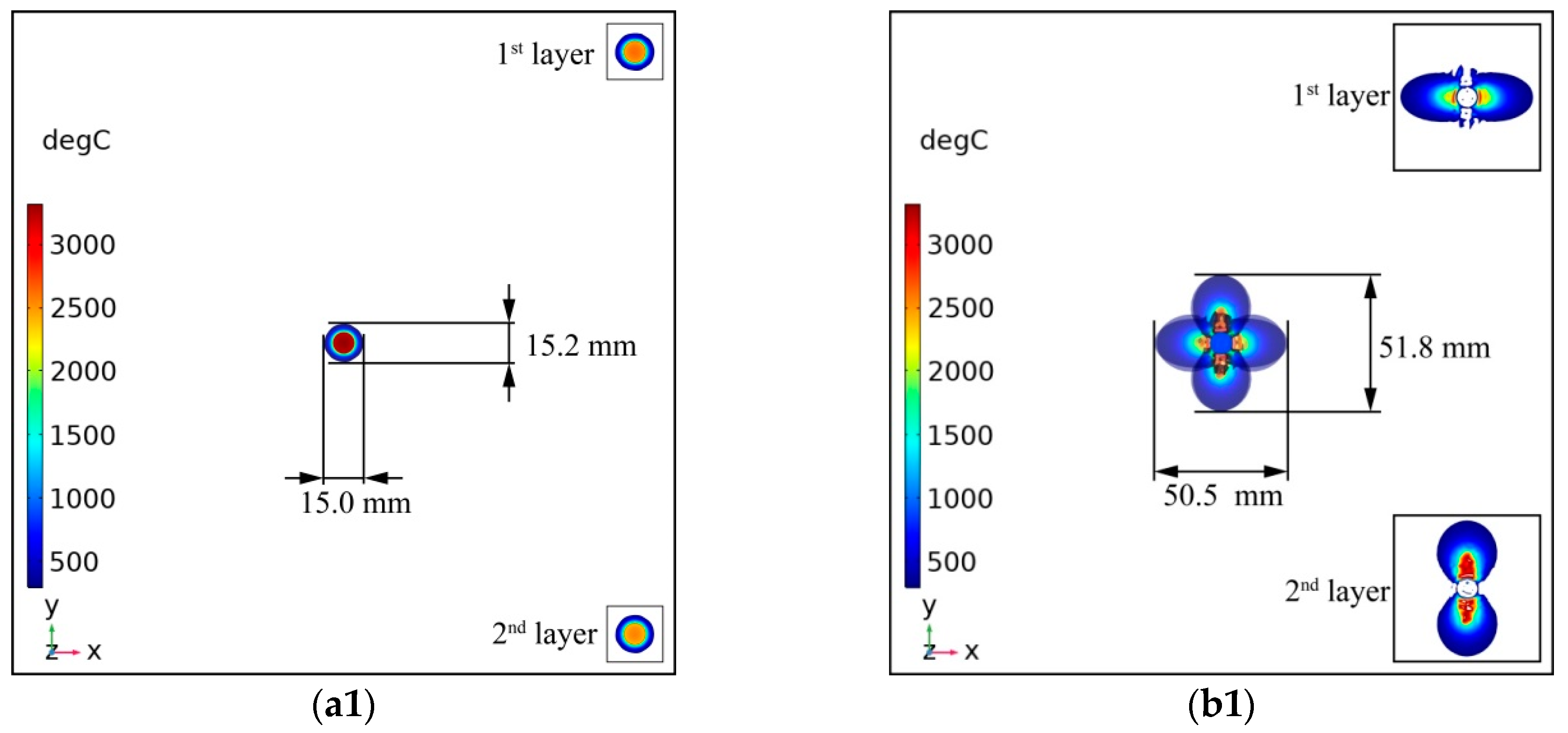
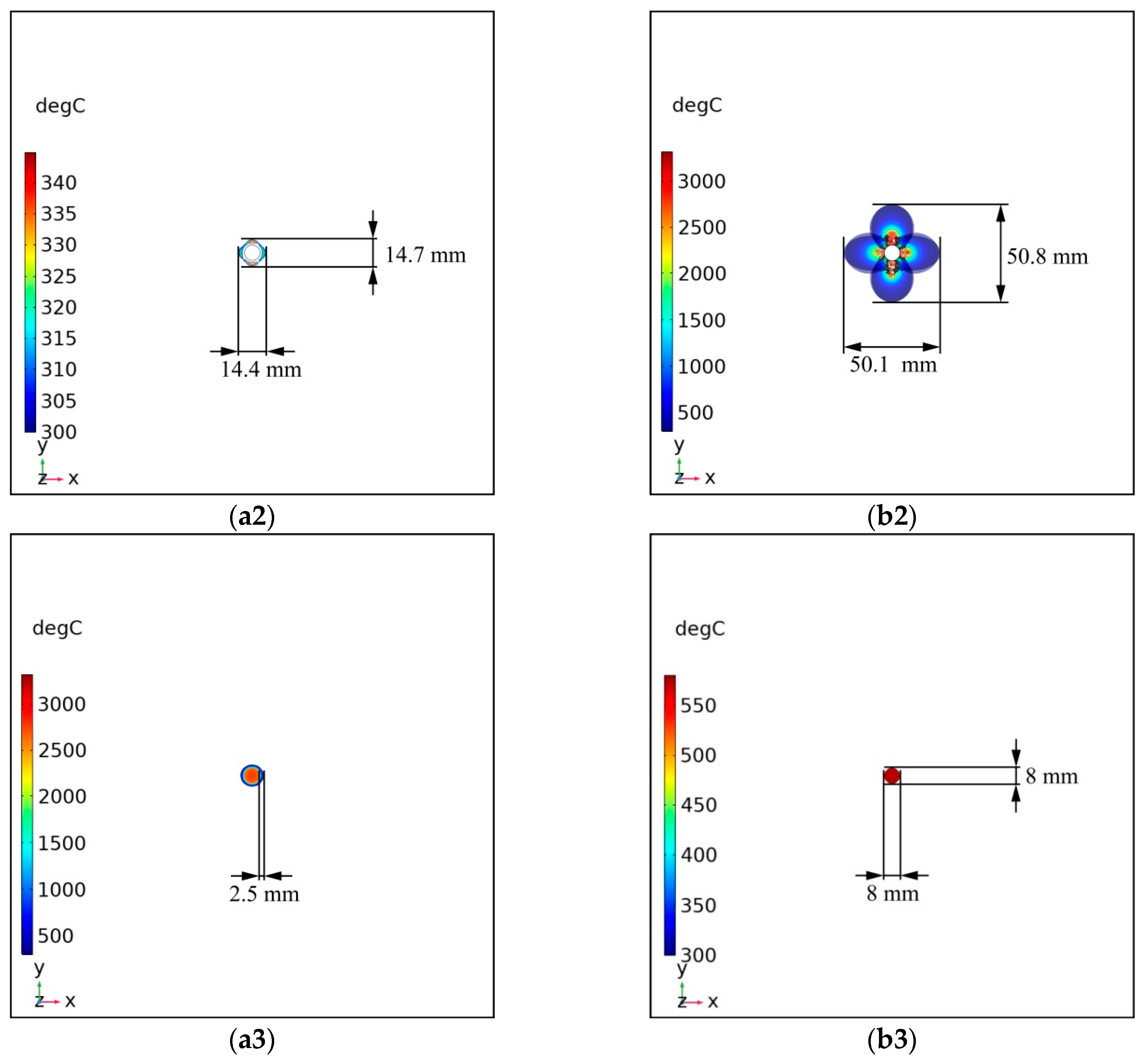
Figure 8(a1–a3) are the temperature profiles of the specimen under component C in the conduction current + heat flux, conduction current, and heat flux simulation models, respectively. Figure 8(a1,a2) indicate that the decomposition damage shape and size of the laminates are similar to each other and that the damage shape is circular. Such decomposition damage shapes, which are similar to the dark-red area in Figure 7a, do not reflect the anisotropy of the CFRP laminates because component C has a long duration, providing Joule heat in sufficient time to spread in all directions. The first layer (0° direction) and the second layer (90° direction) are two orthogonal layers, and their temperature distributions are shown in the upper-right corner and lower-right corner of Figure 8(a1), respectively. The decomposition damage shapes of the two layers are almost identical.
In addition, the temperature of the top of the fastener (in the center of Figure 8(a1)) exceeds 3000 °C after the combination of the conduction current and the heat flux. This temperature is much higher than the melting temperature of the fastener and causes severe ablation damage to the fastener. Figure 8(a3) shows the temperature distribution when using the heat flux model. In this model, the damage to the laminate caused by heat flux is approximately 2.5mm, and the temperature of the fastener is similar to that in the conduction current + heat flux model, which means that the ablation damage of the fastener under the action of component C has an important relationship with the heat flux.
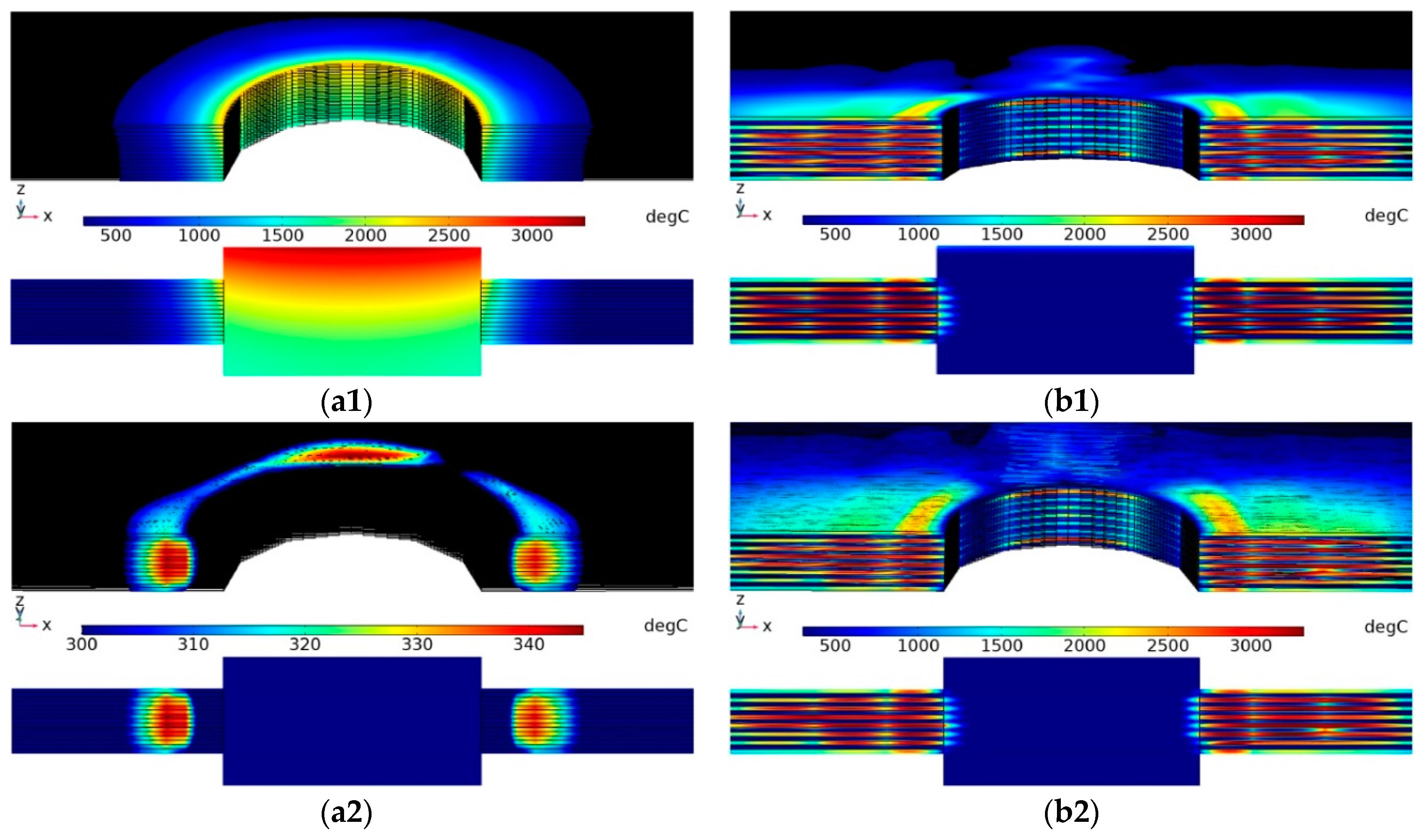
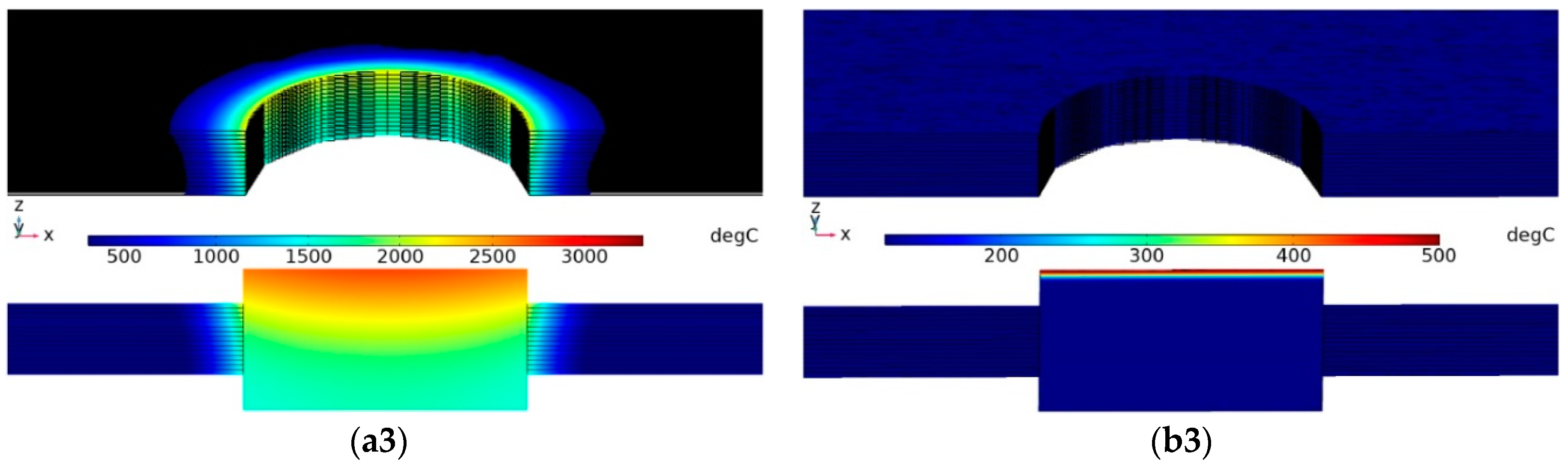
Figure 9(a1–a3) are the cross-sectional temperature profiles of the specimen under component C in three simulation models. The heat diffusion can be inferred from the temperature gradient of the fasteners in Figure 9(a1,a3); heat is transferred to the CFRP laminate along with the fastener, causing the material temperature around the fastener to increase. In Figure 9(a2), the temperature of the fastener is far less than 300 °C and the decomposition damage occurs in a small area around the fastener. Because the damage occurs in the conduction current model, it is completely caused by the Joule heat generated by the conduction current. According to the results of Figure 5a, Figure 8(a1–a3), and Figure 9(a1–a3), a small area of CFRP laminate damage and serious fastener damage will clearly occur under component C. Thus, arc heating (heat flux) is the main cause of fastener damage under component C.
Figure 8(b1–b3) are the temperature profiles of the specimen under component D in the conduction current + heat flux, conduction current, and heat flux simulation models, respectively. Figure 8(b1,b2) show that the decomposition damage shape and size of the specimen were similar, and that the decomposition damage was centered on the fastener and fanned out along the 0° and 90° directions. The decomposition damage in both directions exceeded 50 mm. This decomposition damage shape, which resembles the dark-red area in Figure 7b, reflects the anisotropy of the CFRP laminates because component D has a short duration, which does not provide sufficient time for the Joule heat to spread evenly in all directions. The first layer (0° direction) and the second layer (90° direction) are the two orthogonal layers, and their temperature distributions are shown in the upper-right corner and lower-right corner of Figure 8(a1), respectively. Both layers showed that the decomposition damage in the fiber direction was substantially greater than that perpendicular to the fiber direction. In addition, Figure 8(b1,b3) show that no noticeable temperature rise occurred at the top of the fasteners from the heat flux. Figure 8(b3) is the temperature distribution when the heat flux model is used. In this model, the highest temperature at the top of the fastener is approximately 550 °C, which does not ablate the fastener. There are no visible signs of damage around the fastener, which means that the heat flux has little contribution to the damage of the CFRP with fasteners when component D is applied.
Figure 9(b1–b3) are the cross-sectional temperature profiles of the specimen under component D in three simulation models. The cross-sections of the specimens in Figure 9(b1,b2) show that the Joule heat generated by the conduction current caused the massive decomposition damage area in the laminate, whereas the fasteners remained at a lower temperature. According to the results of Figure 5b, Figure 8(b1–b3), and Figure 9(b1–b3), large CFRP laminate decomposition damage and minor fastener damage will occur under component D. Thus, the Joule heat generated by the conduction current is the leading factor for CFRP laminate decomposition damage under component D.
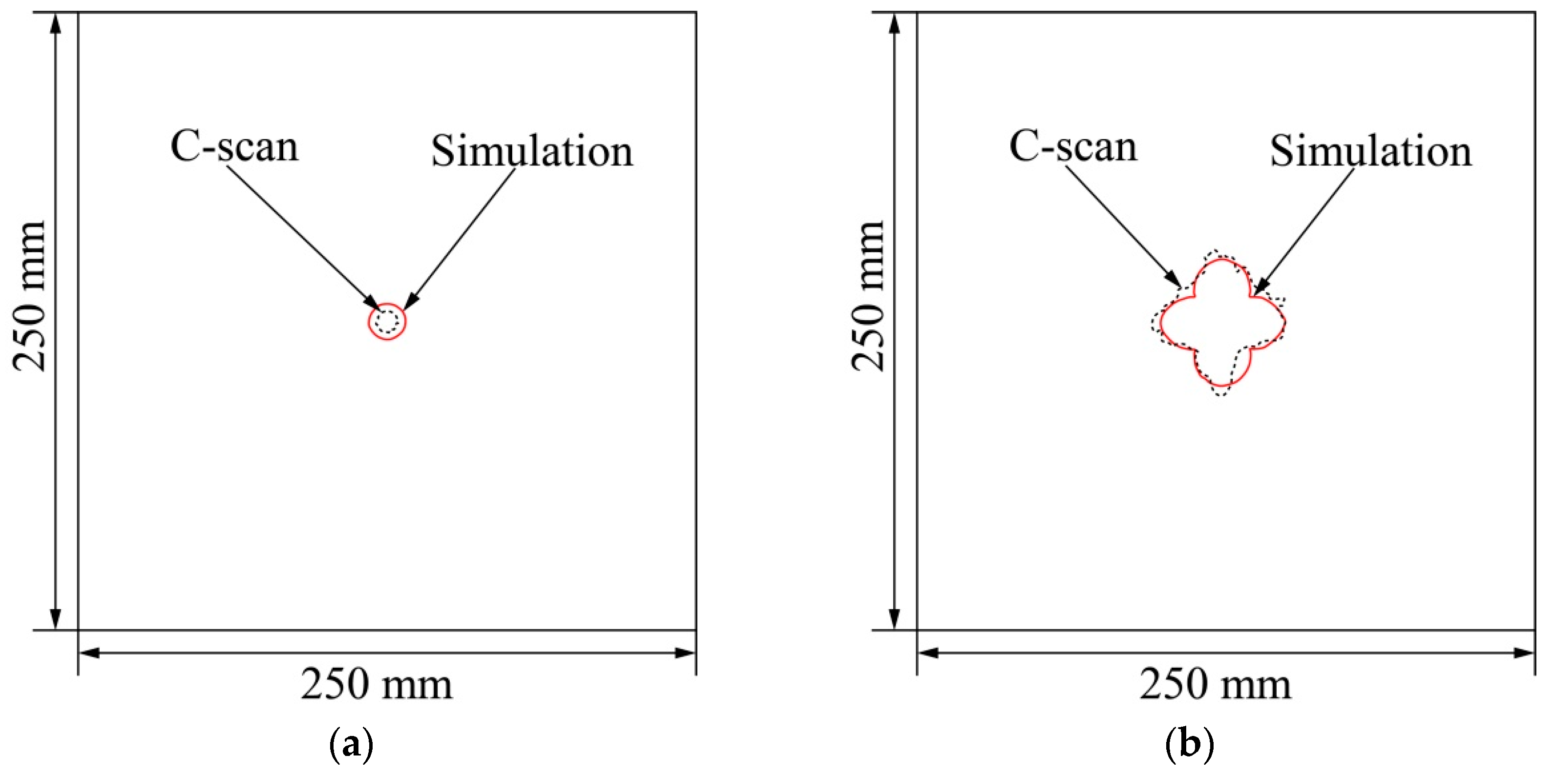
Figure 10 compares the damage profiles in the conduction current + heat flux model (marked with the solid red line) with the thermal decomposition damage and ablation damage profiles in the ultrasonic C-scans (marked with the black dotted line). The damage in the specimen caused by component D is much greater than that caused by component C. Figure 10a,b show that the FEA results are in good agreement with the experimental results. Therefore, it is reliable to study CFRP laminates with fasteners by FEA.
5. Discussion
Dong et al. [17] considered the Joule heat effect and arc heat effect when investigating the damage of CFRP laminates without fasteners under components D and C. Comparing their results with ours, it can be found that there is a significant difference in damage between CFRP laminates without fasteners and CFRP laminates with fasteners with the same lightning current components.
For CFRP laminates without fasteners, the results showed that the Joule heat effect and the arc heat effect could cause damage. Component D controls the area of in-plane damage, while the sequential injection of component C after D aggravates the in-plane damage and tends to increase the damage depth. The Joule heat effect plays a leading role in component D, while the arc heat effect plays a dominant role in component C.
For CFRP laminates with fasteners, when the lightning strike acts on the fastener, because the conductivity of the fastener is approximately 1000 times greater than that of the carbon fibers [36], the lightning current will be discharged through the fastener first and then redistributed in each layer of the laminate in the form of a conduction current. The amplitude of the conduction current in each layer is related to the stacking sequence, the grounding mode, and the electrical conductivity. During the test, the specimen is grounded on four sides. In this grounding method, the conduction current can be scattered along each layer to the ground boundary. According to the surface damage (Figure 5), the fastener hole damage (Figure 6), and the internal damage (Figure 7), the damages induced by components C and D differ markedly. Laminates subjected to component C sustained less damage than those subjected to component D. However, the fasteners were severely ablated under component C and not under component D.
When the gap between the discharge electrode and the laminate is broken down, an arc will be generated, forming a high-temperature ionization region at 30,000 K [15]. For component C, the high-temperature arc, which has a long duration, acts on the fastener. The accumulation of heat makes the fastener gasify. Figure 5a shows that the fastener has sustained serious ablation damage. For component D, because of the short duration, the heat of the high-temperature arc seldom accumulates in the fastener; thus, Figure 5b shows that the fastener has minor ablation damage under component D.
Figure 5b shows that resin damage occurs on the surface of the laminate far from the fastener after component D is applied. This damage should be caused by dielectric surface discharge [12]. The dielectric breakdown model considers that the discharge direction is determined by the local electrical potential gradient. During the lightning strike, a large amount of induced charge will accumulate on the surface of the specimen. When the electric field intensity generated by the accumulated charge exceeds the critical value, discharge will occur on the surface of the material, causing damage to the resin. For component C (Figure 5a), due to the low amplitude of the discharge voltage, dielectric breakdown is less likely to occur; thus, the resin damage on the specimen surface should be caused by the metal droplets splashing and attaching to the surface after the fastener has melted.
During a lightning strike, the resin on the inner wall of the fastener hole is pyrolyzed and gasified, which generates high-temperature, high-pressure gas [37]. The heated gas expands rapidly, producing a high-speed gas flow doped with black particles, which may be the product of carbon fiber sublimation and pyrolysis carbonization at high temperatures [38]. Some of the black particles entered the fastener nut through the gap, whereas the rest remained on the inner wall of the fastener hole (Figure 6).
Figure 7 shows that there is a great difference in the internal damage of the laminates under different lightning components.
For component C, the current amplitude is 200 A. Due to the high current density around the fastener, a large amount of Joule heat can be generated. Moreover, the arc heat will spread to the laminate through the fastener (see Figure 9(a1,a3)). The combined effect of the Joule heat and arc heat results in resin pyrolysis. In the zone far from the fastener, the current density and the arc heat decay rapidly, and no internal damage in this zone can be observed under the C-scan. The internal damage caused by component C is concentrated in a small area around the fastener, as shown in Figure 7a and Figure 8(a1).
For component D, the fastener spreads the conduction current to all the layers, and this current is approximately 6.7 kA per layer. These conduction currents can generate large amounts of Joule heat, allowing the resin to pyrolyze over large areas and release gas. According to Figure 6b, Figure 7b, and Figure 9b, it can be speculated that these high-temperature, high-pressure gases trapped inside the CFRP laminate may cause an internal explosion when the gas pressure reaches a critical level, which will result in serious delamination damage.
6. Conclusions
In this work, components C and D were used in simulated lightning strike tests. Ultrasonic C-scans and stereomicroscopy were used to evaluate the damage sustained by the specimens during the lightning strike tests. Moreover, the electrothermal coupling theory was adopted to model the different effects of the arc heat and Joule heat. The following conclusions are drawn.
(1) The damage to the laminate was concentrated around the fasteners. The conduction current flowed through the fastener to all layers and caused damage in each layer. With increasing distance from the fastener, the current density and the arc heat decayed.
(2) Component D, which had a high current amplitude and a short duration, led to serious surface and internal damage in the CFRP laminate and little damage to the fastener. The damage was mainly caused by the Joule heat generated by the conduction current. Component C, which had a low current amplitude and a long duration, ablated and gasified the fastener and caused less damage to the CFRP laminate. In this process, the arc heating produced by the arc played a leading role.
(3) The temperature profiles in the conduction current + heat flux model were analogous to the thermal decomposition damage and ablation damage profiles from the C-scan. Therefore, the conduction current + heat flux model is reasonable in FEA of CFRPs with fasteners subjected to lightning strikes. The simulation results show an obvious anisotropy in Component D but not in Component C, because component C has sufficient time for the Joule heat to spread in all directions, whereas component D lacks sufficient time.
This work evaluated the damage in CFRP laminates with fasteners subjected to lightning current components C and D and found that the damage under different lightning current components presented unique characteristics. Due to the variety of lightning strikes in nature, the damage induced by other lightning current components and multi-components needs further study on the basis of the research results of the single lightning current component.
Author Contributions
Conceptualization, J.C. and Z.F.; data curation, J.C.; formal analysis, J.C., X.B., and J.L.; funding acquisition, Z.F.; investigation, J.C., X.B., and J.L.; methodology, J.C.; project administration, Z.F.; resources, Z.F.; supervision, Z.F.; validation, J.C.; visualization, J.C., X.B., and J.L.; writing—original draft, J.C.; writing—review and editing, Z.F. All authors have read and agreed to the published version of the manuscript.
Funding
This research was funded by National Key R&D Program of China, grant number 2017YFC1501506.
Conflicts of Interest
The authors declare no conflict of interest.
References
- Zhengchun, D.; Mengrui, Z.; Zhiguo, W.; Jianguo, Y. Design and application of composite platform with extreme low thermal deformation for satellite. Compos. Struct. 2016, 152, 693–703. [Google Scholar] [CrossRef]
- Mishnaevsky, L.; Branner, K.; Petersen, H.N.; Beauson, J.; McGugan, M.; Sørensen, B.F. Materials for Wind Turbine Blades: An Overview. Materials 2017, 10, 1285. [Google Scholar] [CrossRef] [PubMed] [Green Version]
- Chen, C.-C.; Chen, S.-L. Strengthening of Reinforced Concrete Slab-Column Connections with Carbon Fiber Reinforced Polymer Laminates. Appl. Sci. 2020, 10, 265. [Google Scholar] [CrossRef] [Green Version]
- Chen, J.; Fu, Z.; Zhao, Y. Resistance behaviour of carbon fibre-reinforced polymers subjected to lightning strikes: Experimental investigation and application. Adv. Compos. Lett. 2019, 28, 1–10. [Google Scholar] [CrossRef] [Green Version]
- WANG, F.; MA, X.; ZHANG, Y.; Jia, S. Lightning Damage Testing of Aircraft Composite-Reinforced Panels and Its Metal Protection Structures. Appl. Sci. 2018, 8, 1791. [Google Scholar] [CrossRef] [Green Version]
- Guo, Y.; Jia, Y. Thermal damage characteristics of CFRP laminates subjected to lightning strike. In Proceedings of the 21st International Conference on Composite, Xi’an, China, 20–25 August 2017. [Google Scholar]
- Dong, Q.; Guo, Y.; Chen, J.; Yao, X.; Yi, X.; Ping, L.; Jia, Y. Influencing factor analysis based on electrical–Thermal-pyrolytic simulation of carbon fiber composites lightning damage. Compos. Struct. 2016, 140, 1–10. [Google Scholar] [CrossRef]
- Foster, P.; Abdelal, G.; Murphy, A. Understanding how arc attachment behaviour influences the prediction of composite specimen thermal loading during an artificial lightning strike test. Compos. Struct. 2018, 192, 671–683. [Google Scholar] [CrossRef] [Green Version]
- Hirano, Y.; Katsumata, S.; Iwahori, Y.; Todoroki, A. Artificial lightning testing on graphite/epoxy composite laminate. Compos. Part A Appl. Sci. Manuf. 2010, 41, 1461–1470. [Google Scholar] [CrossRef]
- Kirchdoerfer, T.; Liebscher, A.; Ortiz, M. CTH shock physics simulation of non-linear material effects within an aerospace CFRP fastener assembly due to direct lightning attachment. Compos. Struct. 2018, 189, 357–365. [Google Scholar] [CrossRef]
- Yin, J.J.; Li, S.L.; Yao, X.L.; Chang, F.; Li, L.K.; Zhang, X.H. Lightning Strike Ablation Damage Characteristic Analysis for Carbon Fiber/Epoxy Composite Laminate with Fastener. Appl. Compos. Mater. 2016, 23, 821–837. [Google Scholar] [CrossRef]
- Kawakami, H. Lightning Strike Induced Damage Mechanisms of Carbon Fiber Composites. Ph.D. Thesis, University of Washington, Seattle, WA, USA, 2011. [Google Scholar]
- Chemartin, L.; Lalande, P.; Tristant, F. Modeling and simulation of sparking in fastening assemblies. In Proceedings of the International Conference on Lightning and Static Electricity, Seattle, WA, USA, 18–20 September 2013. [Google Scholar]
- Muñoz, R.; Delgado, S.; González, C.; López-Romano, B.; Wang, D.-Y.; LLorca, J. Modeling Lightning Impact Thermo-Mechanical Damage on Composite Materials. Appl. Compos. Mater. 2014, 21, 149–164. [Google Scholar] [CrossRef]
- Abdelal, G.; Murphy, A. Nonlinear numerical modelling of lightning strike effect on composite panels with temperature dependent material properties. Compos. Struct. 2014, 109, 268–278. [Google Scholar] [CrossRef] [Green Version]
- Ogasawara, T.; Hirano, Y.; Yoshimura, A. Coupled thermal–Electrical analysis for carbon fiber/epoxy composites exposed to simulated lightning current. Compos. Part A Appl. Sci. Manuf. 2010, 41, 973–981. [Google Scholar] [CrossRef]
- Dong, Q.; Wan, G.; Guo, Y.; Zhang, L.; Wei, X.; Yi, X.; Jia, Y. Damage analysis of carbon fiber composites exposed to combined lightning current components D and C. Compos. Sci. Technol. 2019, 179, 1–9. [Google Scholar] [CrossRef]
- Hirano, Y.; Reurings, C.; Iwahori, Y. Damage resistance of graphite/epoxy laminates with a fastener subjected to artificial lightning. In Proceedings of the 18th International Conference on Composites Materials, Jeju, Korea, 21–26 August 2011. [Google Scholar]
- Feraboli, P.; Miller, M. Damage resistance and tolerance of carbon/epoxy composite coupons subjected to simulated lightning strike. Compos. Part A Appl. Sci. Manuf. 2009, 40, 954–967. [Google Scholar] [CrossRef]
- Feraboli, P.; Kawakami, H. Damage of Carbon/Epoxy Composite Plates Subjected to Mechanical Impact and Simulated Lightning. J. Aircr. 2010, 47, 999–1012. [Google Scholar] [CrossRef]
- Evans, S.; Jenkins, M.; Cole, M.; Haddad, M.; Carr, D.; Clark, D.; Stone, C.; Fay, A.; Mills, R.; Blair, D. An introduction to a new aerospace lightning direct effects research programme and the significance of Zone 2A waveform components on sparking joints. In Proceedings of the 33rd International Conference on Lightning Protection, Estoril, Lisboa, Portugal, 25–30 September 2016. [Google Scholar]
- Department of Defense Interface Standard-Electromagnetic Environmental Effects Requirements for System; MIL-STD-464A; Defense Threat Reduction Agency: Alexandria, VA, USA, 2002.
- Aircraft Lightning Environment and Related Test Waveforms; SAE ARP5412B; Society of Automotive Engineers: Warrendale, PA, USA, 2013.
- Wang, Y.; Zhupanska, O.I. Modeling of thermal response and ablation in laminated glass fiber reinforced polymer matrix composites due to lightning strike. Appl. Math. Model. 2018, 53, 118–131. [Google Scholar] [CrossRef]
- Chemartin, L.; Lalande, P.; Peyrou, B.; Chazottes, A.; Lago, F. Direct Effects of Lightning on Aircraft Structure: Analysis of the Thermal, Electrical and Mechanical Constraints. J. Aerosp. Lab. 2012, AL05-09, 1–15. [Google Scholar]
- Wang, Y. Multiphysics analysis of lightning strike damage in laminated carbon/glass fiber reinforced polymer matrix composite materials: A review of problem formulation and computational modeling. Compos. Part A Appl. Sci. Manuf. 2017, 101, 543–553. [Google Scholar] [CrossRef]
- Guo, Y.; Dong, Q.; Chen, J.; Yao, X.; Yi, X.; Jia, Y. Comparison between temperature and pyrolysis dependent models to evaluate the lightning strike damage of carbon fiber composite laminates. Compos. Part A Appl. Sci. Manuf. 2017, 97, 10–18. [Google Scholar] [CrossRef]
- Lago, F.; Gonzalez, J.J.; Freton, P.; Uhlig, F.; Lucius, N.; Piau, G.P. A numerical modelling of an electric arc and its interaction with the anode: Part III. Application to the interaction of a lightning strike and an aircraft in flight. J. Phys. D Appl. Phys. 2006, 39, 2294–2310. [Google Scholar] [CrossRef]
- Lee, J.; Lacy, T.E.; Pittman, C.U.; Mazzola, M.S. Thermal response of carbon fiber epoxy laminates with metallic and nonmetallic protection layers to simulated lightning currents. Polym. Compos. 2018, 39, E2149–E2166. [Google Scholar] [CrossRef]
- Gao, S.-P.; Lee, H.M.; Gao, R.X.-K.; Lim, Q.F.; Thitsartarn, W.; Liu, E.-X.; Png, C.E. Effective modeling of multidirectional CFRP panels based on characterizing unidirectional samples for studying the lightning direct effect. In Proceedings of the 32nd URSI General Assembly and Scientific Symposium, Montreal, QC, Canada, 19–26 August 2017. [Google Scholar]
- Chen, H.; Wang, F.S.; Ma, X.T.; Yue, Z.F. The coupling mechanism and damage prediction of carbon fiber/epoxy composites exposed to lightning current. Compos. Struct. 2018, 203, 436–445. [Google Scholar] [CrossRef]
- Dong, Q.; Wan, G.; Ping, L.; Guo, Y.; Yi, X.; Jia, Y. Coupled thermal-mechanical damage model of laminated carbon fiber/resin composite subjected to lightning strike. Compos. Struct. 2018, 206, 185–193. [Google Scholar] [CrossRef]
- Shen, Q.; Omar, M.; Dongri, S. Ultrasonic NDE Techniques for Impact Damage Inspection on CFRP Laminates. JMSR 2011, 1. [Google Scholar] [CrossRef]
- Kamiyama, S.; Hirano, Y.; Ogasawara, T. Delamination analysis of CFRP laminates exposed to lightning strike considering cooling process. Compos. Struct. 2018, 196, 55–62. [Google Scholar] [CrossRef]
- Fu, S.; Guo, Y.; Shi, L.; Zhou, Y. Investigation on temperature behavior of CFRP during lightning strike using experiment and simulation. Polym. Compos. 2019, 592, 16. [Google Scholar] [CrossRef]
- Che, H.; Gagné, M.; Rajesh, P.S.M.; Klemberg-Sapieha, J.E.; Sirois, F.; Therriault, D.; Yue, S. Metallization of Carbon Fiber Reinforced Polymers for Lightning Strike Protection. J. Mater. Eng. Perform. 2018, 27, 5205–5211. [Google Scholar] [CrossRef]
- Teulet, P.; Billoux, T.; Cressault, Y.; Masquère, M.; Gleizes, A.; Revel, I.; Lepetit, B.; Peres, G. Energy balance and assessment of the pressure build-up around a bolt fastener due to sparking during a lightning impact. Eur. Phys. J. Appl. Phys. 2017, 77, 2080101–2080113. [Google Scholar] [CrossRef] [Green Version]
- Sun, J.; Yao, X.; Tian, X.; Chen, J.; Wu, Y. Damage Characteristics of CFRP Laminates Subjected to Multiple Lightning Current Strike. Appl. Compos. Mater. 2018, 30, 156. [Google Scholar] [CrossRef]
Figure 1.
(a) Assembly diagram of the CFRP with a fastener; (b) the clamp and connection.

Figure 2.
Simulated lightning current waveforms in [23].
Figure 2.
Simulated lightning current waveforms in [23].

Figure 3.
Lightning current waveforms used in the present study: (a) component C; (b) component D.

Figure 4.
Finite element model and boundary conditions.

Figure 5.
Surface damage in the specimens after lightning strike: (a) component C; (b) component D.

Figure 6.
Damage in the fastener hole of the specimens after lightning strikes: (a) component C; (b) component D. (c) Specimen cutting diagram for microscopic evaluation.
Figure 6.
Damage in the fastener hole of the specimens after lightning strikes: (a) component C; (b) component D. (c) Specimen cutting diagram for microscopic evaluation.


Figure 7.
Ultrasonic C-scan results of specimens after lightning strikes: (a) component C; (b) component D.
Figure 7.
Ultrasonic C-scan results of specimens after lightning strikes: (a) component C; (b) component D.

Figure 8.
Temperature profiles of specimens under different simulation models and different lightning current components: component C in the (a1) conduction current + heat flux model, (a2) conduction current model, and (a3) heat flux model; component D in the (b1) conduction current + heat flux model, (b2) conduction current model, and (b3) heat flux model.


Figure 9.
Cross-sectional temperature profiles of the fastener hole under different simulation models and different lightning current components: component C in the (a1) conduction current + heat flux model, (a2) conduction current model, and (a3) heat flux model; component D in the (b1) conduction current + heat flux model, (b2) conduction current model, and (b3) heat flux model.


Figure 10.
Damage comparison between simulated lightning strikes and finite element simulations: (a) component C; (b) component D.
Figure 10.
Damage comparison between simulated lightning strikes and finite element simulations: (a) component C; (b) component D.


Table 1.
Physical properties of the specimen.
| Tempe-rature | Density | Specific Heat | Thermal Conductivity | Electrical Conductivity | |||
|---|---|---|---|---|---|---|---|
| Longi-tudinal | Transverse/through-thickness | Longi-tudinal | Transverse | Through-thickness | |||
| 25 | 1472 | 1176 | 6.578 | 0.723 | 17,800 | 10.4 | 2.8 |
| 300 | 1472 | 2048 | 9.617 | 0.633 | 17,800 | 10.4 | 2.8 |
| 500 | 1110 | 1454 | 7.166 | 0.423 | 17,800 | 2000 | 2000 |
| 510 | 1110 | 1454 | 7.166 | 0.423 | 17,800 | 2000 | 2000 |
| 3316 1 | 1110 | 2146 | 7.166 | 0.423 | 17,800 | 20,000 | 20,000 |
| >3316 2 | 1110 | 5875 | 1.0 × 10⁸ | 1.0 × 10⁸ | 1.0 × 10⁸ | 1.0 × 10⁸ | 1.0 × 10⁸ |
Table 2.
Physical properties of stainless steel.
| Density | Specific Heat | Electrical Conductivity | |
|---|---|---|---|
| 7850 | 4.75 × 10² | 44.5 | 4.032 × 10⁶ |
Table 3.
Simulation model.
| Simulation Model | Function |
|---|---|
| Conduction current + heat flux | Simulate the combined effect of the arc and conduction current |
| Conduction current | Simulate the effect of the conduction current |
| Heat flux | Simulate the effect of the arc |
© 2020 by the authors. Licensee MDPI, Basel, Switzerland. This article is an open access article distributed under the terms and conditions of the Creative Commons Attribution (CC BY) license (http://creativecommons.org/licenses/by/4.0/).
Share and Cite
MDPI and ACS Style
Chen, J.; Bi, X.; Liu, J.; Fu, Z. Damage Investigation of Carbon-Fiber-Reinforced Plastic Laminates with Fasteners Subjected to Lightning Current Components C and D. Appl. Sci. 2020, 10, 2147. https://doi.org/10.3390/app10062147
AMA Style
Chen J, Bi X, Liu J, Fu Z. Damage Investigation of Carbon-Fiber-Reinforced Plastic Laminates with Fasteners Subjected to Lightning Current Components C and D. Applied Sciences. 2020; 10(6):2147. https://doi.org/10.3390/app10062147
Chicago/Turabian StyleChen, Jian, Xiaolei Bi, Juan Liu, and Zhengcai Fu. 2020. "Damage Investigation of Carbon-Fiber-Reinforced Plastic Laminates with Fasteners Subjected to Lightning Current Components C and D" Applied Sciences 10, no. 6: 2147. https://doi.org/10.3390/app10062147
Note that from the first issue of 2016, this journal uses article numbers instead of page numbers. See further details here.