Influence of Current Density on the Microstructure of Carbon-Based Cathode Materials during Aluminum Electrolysis


1
College of Materials Science and Engineering, Henan University of Science and Technology, Luoyang 471023, China
2
Collaborative Innovation Center of Nonferrous Metals Henan Province, Luoyang 471023, China
3
Henan Key Laboratory of Non-ferrous Materials Science & Processing Technology, Luoyang 471023, China
*
Author to whom correspondence should be addressed.
Appl. Sci. 2020, 10(7), 2228; https://doi.org/10.3390/app10072228
Submission received: 24 February 2020
/
Revised: 13 March 2020
/
Accepted: 24 March 2020
/
Published: 25 March 2020
(This article belongs to the Special Issue Carbon Nanostructures: Fabrication and Applications)
Abstract
:Sodium expansion plays an important role in cathode deterioration during aluminum electrolysis. In this work, the sodium expansion of semigraphitic cathode material has been measured at various cathodic current densities using a modified Rapoport apparatus. We have studied the microstructural changes of carbon cathodes after aluminum electrolysis using high-resolution transmission electron microscopy (HRTEM). Because of an increasing trend toward higher amperage in retrofitted aluminum reduction cells, an investigation is conducted both at a representative cathode current density (0.45 A/cm2) and at a high cathodic current density (0.7 A/cm2). The results indicate that the microstructures of carbon cathodes can be modified by Joule heating and electrostatic charging with higher current densities during aluminum electrolysis. With the penetration of the sodium and melt, zigzag and armchair edges, disordered carbon, and exfoliation of the surface layers may appear in the interior of the carbon cathode. The penetration of the sodium and melt causes remarkable stresses and strains in the carbon cathodes, that gradually result in performance degradation. This shows that increasing the amperage in aluminum reduction cells may exacerbate the material deterioration of the cathodes.
1. Introduction
The aluminum electrolysis process has continued to make improvements to energy conservation and emissions reductions, while increasing production and productivity at the same time [1,2]. Once the cell is shut down and drained, every day of extended operation brings a substantial saving for the aluminum industry [3]. To achieve these goals, major efforts have been made to extend the service life of an industrial aluminum induction cell, which is the most important equipment in electrolytic production of aluminum [4]. The physical performance of the carbon cathode can be influenced enormously by the chemical contamination phenomenon [5]. In addition, cell life has long been associated with the properties of cathode blocks, often particularly with their degradation caused by the penetration of the melt and sodium towards higher temperatures [6]. Therefore, investigation of the sodium expansion of carbon cathodes is of vital importance for better controlling cathode quality and its performance in industrial aluminum reduction cells.
A number of researchers have reported that sodium expansion is one of the main reasons for cathode deterioration during aluminum electrolysis. Zolochevsky was the first to measure the sodium expansion of semigraphitic cathode material with three current density values through the use of the Rapoport–Samoilenko-type apparatus. Moreover, he has established a model for the relationship between sodium expansion and time [7]. Hjertenæs determined a ReaxFF parameter set to describe sodium interactions with graphitic carbon by applying molecular dynamics methods [8]. Recently, current density has received research attention due to its effect on the electrolytic process. Reinforced current is both the development trend for the current world aluminum electrolysis industry and the urgent demand of the aluminum industrial development of China. The stress and strain of graphite composite electrodes have recently been measured during electrochemical cycling [9]. It has been found that the current density affects the exchange rate of lithium ions and further affects the stress and strain of graphite electrodes. In addition, the current density can control the morphology and crystallinity of graphene nanoribbons by Joule heating [10]. In order to decrease cathode deterioration, an understanding of the microstructure change of carbon cathode during aluminum electrolysis on the atomic scales is desired.
However, so far only limited information is available about the influence of current density on the microstructure of carbon cathodes during aluminum electrolysis. This work presents the in-depth microstructure investigations of carbon cathodes including the atomic arrangement and the formation of sharp zigzag and armchair edges.
2. Materials and Methods
2.1. Materials
The electrolyte was composed of 5 wt.% CaF2 and 8wt.% Al2O3 corresponding to CR (molecular ratio) of NaF/AlF3 equal to 2.5. Among them, Na3AlF6, CaF2, and Al2O3 were analytical reagents. Aluminum fluoride was obtained by sublimation three times with purity above 99.5 pct. All the listed chemicals were dried inside a 423 K (150 ℃) furnace for 24 hours in a dry box before use. The cathode sample comprises 35 percent electrocalcined anthracites and 65 percent graphite.
2.2. Cell design and Electrolysis Procedure
The modified Rapopart system developed by our group was used to conduct the related tests. The main structure of the equipment was presented in Figure 1. A high purity graphite crucible acted as the anode during electrolysis. The crucible was fitted with a boron nitride plate on the bottom to prevent a short circuit. The cylindrical cathode sample (d = 25 mm, h = 50 mm) was glued with the cathode bar by carbon glue. The electric current flowed through the anode rod, the sidewall of the graphite crucible and the melt to the cathode specimen, and the cathode bar was connected to the transducer. The signals of the sodium expansion were written once a minute into a computer linked to the LVD (Low Voltage Directive) transducer. The crucible contained a total of 200 g electrolyte.
The cell was heated to the operating temperature of 940 °C and kept for 1 h before immersing the cathode and electrifying 120 min afterward. The current and the cell voltage were supplied by a high-precision DC (Direct Current) stabilized voltage source. The cathode current density was 0.45 A/cm2 and 0.7 A/cm2, respectively, and the current was kept constant throughout each test. After electrolysis, the cathode sample was lifted above the melt and cooled inside the furnace to room temperature.
2.3. Microstructure Characterization
Specimens for TEM (Transmission Electron Microscope) and HRTEM (High-resolution Transmission Electron Microscope) analyses were prepared according to the following procedure. First, slices of 600 μm in thickness were cut off in the direction perpendicular to the bottom plate of the cathode sample using a corundum wheel on a low speed saw, and polished down to a thickness of 130 μm with a series of SiC papers down to 800 grit. Then, they were mechanically punched into φ3 mm discs. Final preparation of the specimens was ion milling using an ion mill under conditions of a current density of 25~30 mA and an incidence angle to the surface of ± 4°.
3. Results and Discussion
3.1. Effect of the Cathode Current Density on Sodium Expansion
Figure 2a,b show the sodium expansion measurements of semigraphitic cathode materials with the two levels of a cathode current density at 20 min and 120 min, respectively. At the beginning of electrolysis, as the penetration of the electrolyte and sodium and the formation of the graphite–sodium intercalation progresses, sodium expansion develops at a faster rate. The reason is that the interaction of alkali ions with carbon cathodes generates internal stresses within the electrode structure and leads to an increase in the interlayer space [11,12]. The macroscopic strain generated in the carbon cathode is closely related to changes in the graphite interlayer spacing at atomic scales. In addition, the formation of intercalation compounds in this stage exacerbates the development of stresses and strains in the carbon cathodes [13,14].
However, the decreasing tendency of the sodium expansion rate is observed with the continuous electrolysis, but the sodium expansion approaches asymptotically to a constant. The reason is that the macroscopic expansion developed in the carbon cathode has a close relationship with changes in the interlayer space at the atomic length scales, as different amounts of intercalation compounds are formed between the graphite layers [15,16,17]. In addition, the higher the current densities, the faster the sodium concentration increases in a cathode sample [7]. Therefore, the sodium expansion of the carbon cathode is bigger with higher current densities at the beginning of electrolysis. The inhomogeneous sodium concentration in the carbon causes the occurrence of the diffusion-induced stresses in the carbon cathode. Such heterogeneities are even more serious in the carbon and induce rapid stress and strain gradients that finally result in the chemical and physical degradation of the carbon cathodes [18,19]. However, the sodium concentration at each point of the carbon cathode keeps a constant value after sodium saturation, thus, the sodium expansion of the carbon cathode has the same value in the end with various current densities. In a word, with fewer sodium and melt penetrated into the carbon cathode, the strain response is also decreased. In order to further study the effect of the current density on the microstructure of the carbon cathodes, high-resolution transmission electron microscopy, given in Figure 3, shows the atomic arrangement of graphite crystals at testing 20 min with various current densities.
3.2. Effect of the Cathode Current Density on the Microstructure of Carbon Cathodes
As indicated in Figure 3, despite the penetration of the sodium and melt, the lattice fringes in the carbon cathode presented in an orderly permutation (Figure 3a) after aluminum electrolysis with normal current densities, showing the maintaining of perfect layer structure in the graphite. However, at higher current densities, the whole outline of the structure in Figure 3b appears to be similar with that of a tube. The appearance of sharp curves, as in Figure 3b, and other discontinuities, indicate that the carbon cathode has experienced substantial mechanical damage. Obviously, the higher current density may have an adverse effect on the carbon cathode performance. When discussing the influence of an electric current on the structure of graphite, it is interesting to note the recent works of a group of researchers at Cambridge University, who presented in situ Joule heating of graphite ‘nanoribbons’ inside a TEM. The project team called these structures zigzag and armchair edges [12]. In order to further observe the morphologies and the atomic arrangement of the carbon cathodes with a high current density, Figure 4 shows the microstructures of the semigraphitic cathode at testing time 120 min with a cathode current density of 0.7 A/cm2.
As shown in Figure 4, higher current densities led to the formation of zigzag and armchair edges (Figure 4a,b), disordered carbon (Figure 4c), and the exfoliation of graphite flakes (Figure 4d). The microstructural changes of carbon cathodes resulted as a consequence of Joule heating and electrostatic charging, and the latter was the main reason [20]. While the electronic states of graphite are localized along the edges, zigzag-edged graphene ribbons are unique graphene structures. Because the electronic distribution in the carbon cathode is rather extensive at higher current densities, the electronic stream in zigzag-edged zones goes down mostly these zigzag edges. When a zigzag edge runs into another edge, the electronic movement is decreased significantly, and a large resistance is produced at the junction in the system. Therefore, heating will promote an electron stream away from the edge junction or, if sufficient energy is consumed at the junction, will lead to a change in the microstructure [10]. In this case, if sufficient energy is consumed this way, the carbon atom will rearrange partly until electronic flow is rebuilt again. Beginning from a zigzag edge, this can develop if the microstructure is transformed into a zigzag edge. Therefore, zigzag–zigzag junctions are the preferred form. The kink that can form from anywhere on the zigzag edges will develop along the same edges easily. After these kinks sweep through, 1 or a few zigzag atomic rows will slowly go away. This renders graphene with mainly zigzag edges, joined by small armchair edge fragments [21].
With the evolution of the diffusion-induced stresses in the carbon cathode, there was a remarkable change in the arrangement of the carbon atoms. As demonstrated by Figure 4c, the microstructure of the carbon cathode was characterized as less organized carbon, which was consistent with the results of creep deformation investigation [22]. This showed that better-ordered carbons in the bulk changed to disordered carbons at high temperatures and under sodium expansion. When an electric field applied to the carbon cathodes, the van der Waals forces between adjacent graphene layers could be reduced dramatically. The higher were the current densities, the more was the accumulated electrostatic charge in the layers, and this charge accumulation resulted in repulsion between the layers, separation, and exfoliation of the surface layers [23,24]. Obviously, higher current densities facilitated the exfoliation of graphite flakes from their basal planes in the filler particles, as indicated in Figure 4d. By combined analysis of sodium expansion curves and TEM, the results suggest that high current densities can cause the mechanical failure of carbon cathodes during aluminum electrolysis. In industrial practice, care needs to be taken to limit the maximum current density for optimizing production processes. The microstructure of the fractured surfaces of carbon cathodes was also studied using scanning electron microscope.
Figure 5a,b show SEM images of fractured surfaces of the carbon cathodes at testing 120 min with a current density of 0.45 A/cm2 and 0.7 A/cm2, respectively. Microscopic rearrangement of graphite flakes can be clearly observed from two groups. Figure 5a shows the deformation in-plane behavior. The edges of the fractured layers show zigzag nature as indicated in Figure 5b. The zigzag nature of the fracture surface reveals the crack developed easily along the sheet edges. This is consistent with the strong bonding nature within the planes and relatively weaker bonding between the sheet edges. Because of vacancies and Stone–Wales defects, the zigzag fracture appears along the sheet edges. These defects play a crucial role for the fracture along the sheet edges.
4. Conclusions
This paper studies the mechanical failure of carbon cathodes during aluminum electrolysis at various current densities. The change of the microstructure of carbon cathodes indicates that the current density directly correlates with the performance of carbon cathodes. The following summarizes new ideas with the results from this research work.
The higher a current density is, the larger the sodium expansion is at first. When the sodium concentration in the carbon cathode reaches saturation, the sodium expansion has little relationship with the current density.
High current densities can modify the structure of the carbon cathode by Joule heating and electrostatic charging and produce atomically smooth zigzag or armchair edges during aluminum electrolysis, which brings about an adverse effect on the performance of the carbon cathode.
The decreased van der Waals forces between adjacent graphene layers make the surface layers of graphite exfoliate easily.
Author Contributions
W.W. wrote the paper; K.S. performed the experiments. All authors have read and agreed to the published version of the manuscript.
Funding
This research was funded by the National Natural Science Foundation of China (No.U1704154).
Conflicts of Interest
The authors declare no conflict of interest.
References
- Tian, Z.; Lai, Y.; Shu, Y.; Jie, L.; Hwang, J.Y.; Liu, Y. Anodic corrosion behavior of NiFe2O4-based cermet in Na3AlF6-K3AlF6-AlF3 for aluminum electrolysis. Metall. Mater. Trans. B 2015, 46, 1257–1261. [Google Scholar] [CrossRef]
- Wang, W.; Sun, K.; Liu, H. Effects of different aluminum sources on morphologies and properties of ceramic floor tiles from red mud. Constr. Build. Mater. 2020, 241, 118119. [Google Scholar] [CrossRef]
- Wei, S.; Xu, L. Review on research progress of steel and iron wear-resistant material. Acta. Metall. Sinica. [CrossRef]
- Picard, D.; Fafard, M.; Soucy, G.; Bilodeau, J.F. Room temperature long-term creep/relaxation behaviour of carbon cathode material. Mater. Sci. Eng. A 2008, 496, 366–375. [Google Scholar] [CrossRef]
- Chauke, L.; Garbers-Craig, A.M. Reactivity between carbon cathode materials and electrolyte based on industrial and laboratory data. Carbon. 2013, 58, 40–45. [Google Scholar] [CrossRef] [Green Version]
- Wei, W.; Chen, W.; Gu, W. High-resolution TEM microscopy study of the creep behaviour of carbon-based cathode materials. Mater. Sci. Eng. A 2017, 687, 107–112. [Google Scholar]
- Zolochevsky, A.; Hop, J.G.; Servant, G.; Foosnæs, T.; Øye, H.A. Rapoport–Samoilenko test for cathode carbon materials: I. Experimental results and constitutive modelling. Carbon 2003, 41, 497–505. [Google Scholar] [CrossRef]
- Hjertenæs, E.; Nguyen, A.Q.; Koch, H. A Reactive ReaxFF Force field for sodium intrusion in graphitic cathodes. Phys. Chem. Chem. Physm. 2016, 18, 31431. [Google Scholar] [CrossRef]
- Tavassol, H.; Jones, E.M.; Sottos, N.R.; Gewirth, A.A. Electrochemical stiffness in lithium-ion batteries. Nat. Mater. 2016, 15, 1182. [Google Scholar] [CrossRef]
- Xiaoting, J.; Mario, H.; Vincent, M.; Sumpter, B.G.; Jessica, C.D.; Manuel, R.H.J.; Hyungbin, S.; Ya-Ping, H.; Alfonso, R.; Jing, K. Controlled formation of sharp zigzag and armchair edges in graphitic nanoribbons. Science 2009, 323, 1701–1705. [Google Scholar]
- Chon, M.J.; Sethuraman, V.A.; Mccormick, A.; Srinivasan, V.; Guduru, P.R. Real-time measurement of stress and damage evolution during initial lithiation of crystalline silicon. Phys. Rev. Lett. 2011, 107, 045503. [Google Scholar] [CrossRef] [PubMed]
- Tavassol, H.; Chan, M.K.; Catarello, M.G.; Greeley, J.; Cahill, D.G.; Gewirth, A.A. Surface coverage and SEI induced electrochemical surface stress changes during Li deposition in Li-ion battery anodes. J. Electrochem. Soc. 2013, 160, A888. [Google Scholar] [CrossRef]
- Mukhopadhyay, A.; Tokranov, A.; Xiao, X.; Sheldon, B.W. Stress development due to surface processes in graphite electrodes for Li-ion batteries: A first report. Electrochim. Acta 2012, 66, 28–37. [Google Scholar] [CrossRef]
- Sethuraman, V.A.; Chon, M.J.; Shimshak, M.; Srinivasan, V.; Guduru, P.R. In situ measurements of stress evolution in silicon thin films during electrochemical lithiation and delithiation. J. Power Sources 2011, 195, 5062–5066. [Google Scholar] [CrossRef] [Green Version]
- Qiu, S.; Xiao, L.; Sushko, M.L.; Han, K.S.; Shao, Y.; Yan, M.; Liang, X.; Mai, L.; Feng, J.; Cao, Y.; et al. Manipulating adsorption–insertion mechanisms in nanostructured carbon materials for high-efficiency sodium ion storage. Adv. Energy Mater. 2017, 7, 1700403. [Google Scholar] [CrossRef]
- Wang, W.; Chen, W.; Liu, H.; Zhang, C. Atomic scale investigations of carbon-based cathode materials deformation mechanism during aluminum electrolysis. Diamond Relat. Mater. 2019, 95, 14–19. [Google Scholar]
- Wang, W.; Chen, W.; Liu, H.; Zhang, H. Ripplocations, kink bands and delamination cracks in carbon cathode materials. Carbon Lett. 2019, 29, 377–383. [Google Scholar]
- Martin, E.; Federica, M.; Marco, S.; Vanessa, W. Visualization and quantification of electrochemical and mechanical degradation in Li ion batteries. Science 2013, 342, 716–720. [Google Scholar]
- Mukhopadhyay, A.; Sheldon, B.W. Deformation and stress in electrode materials for Li-ion batteries. Prog. Mater. Sci. 2014, 63, 58–116. [Google Scholar] [CrossRef]
- Huang, J.Y.; Chen, S.; Ren, Z.F.; Chen, G.; Dresselhaus, M.S. Real-time observation of tubule formation from amorphous carbon nanowires under high-bias Joule heating. Nano Lett. 2006, 6, 1699–1705. [Google Scholar] [CrossRef]
- Huang, J.Y.; Ding, F.; Yakobson, B.I.; Lu, P.; Qi, L.; Li, J. In situ observation of graphene sublimation and multi-layer edge reconstructions. Proc. Natl. Acad. Sci. USA 2009, 106, 10103–10108. [Google Scholar] [CrossRef] [PubMed] [Green Version]
- Wang, W.; Chen, W. Raman spectroscopy studies of carbon-based cathode materials during aluminum electrolysis. Arch. Metall. Mater. 2019, 64, 1257–1261. [Google Scholar]
- Wang, B.; Wolfe, D.E.; Terrones, M.; Haque, M.A.; Ganguly, S.; Roy, A.K. Electro-graphitization and exfoliation of graphene on carbon nanofibers. Carbon 2017, 117, 201–207. [Google Scholar] [CrossRef]
- Liu, Y.; Wang, H.; Yang, K.; Yang, Y.; Ma, J.; Pan, K.; Wang, G.; Ren, F.; Pang, H. Enhanced electrochemical performance of Sb2O3 as an anode for Lithium-ion batteries by a stable cross-linked binder. Appl. Sci. Basel 2019, 9, 2677. [Google Scholar] [CrossRef] [Green Version]
Figure 1.
Schematic diagram of a modified Rapoport. (1) Stainless steel cover (2) Argon gate (3) C-Ni-Cr alloy cathode rod (4) High purity graphite crucible. (5) Electrolyte (6) Semigraphitic cathode (7) Boron nitride plate. (8) Furnace (9) Graphite mechanical support. (10) Argon inlet.
Figure 1.
Schematic diagram of a modified Rapoport. (1) Stainless steel cover (2) Argon gate (3) C-Ni-Cr alloy cathode rod (4) High purity graphite crucible. (5) Electrolyte (6) Semigraphitic cathode (7) Boron nitride plate. (8) Furnace (9) Graphite mechanical support. (10) Argon inlet.
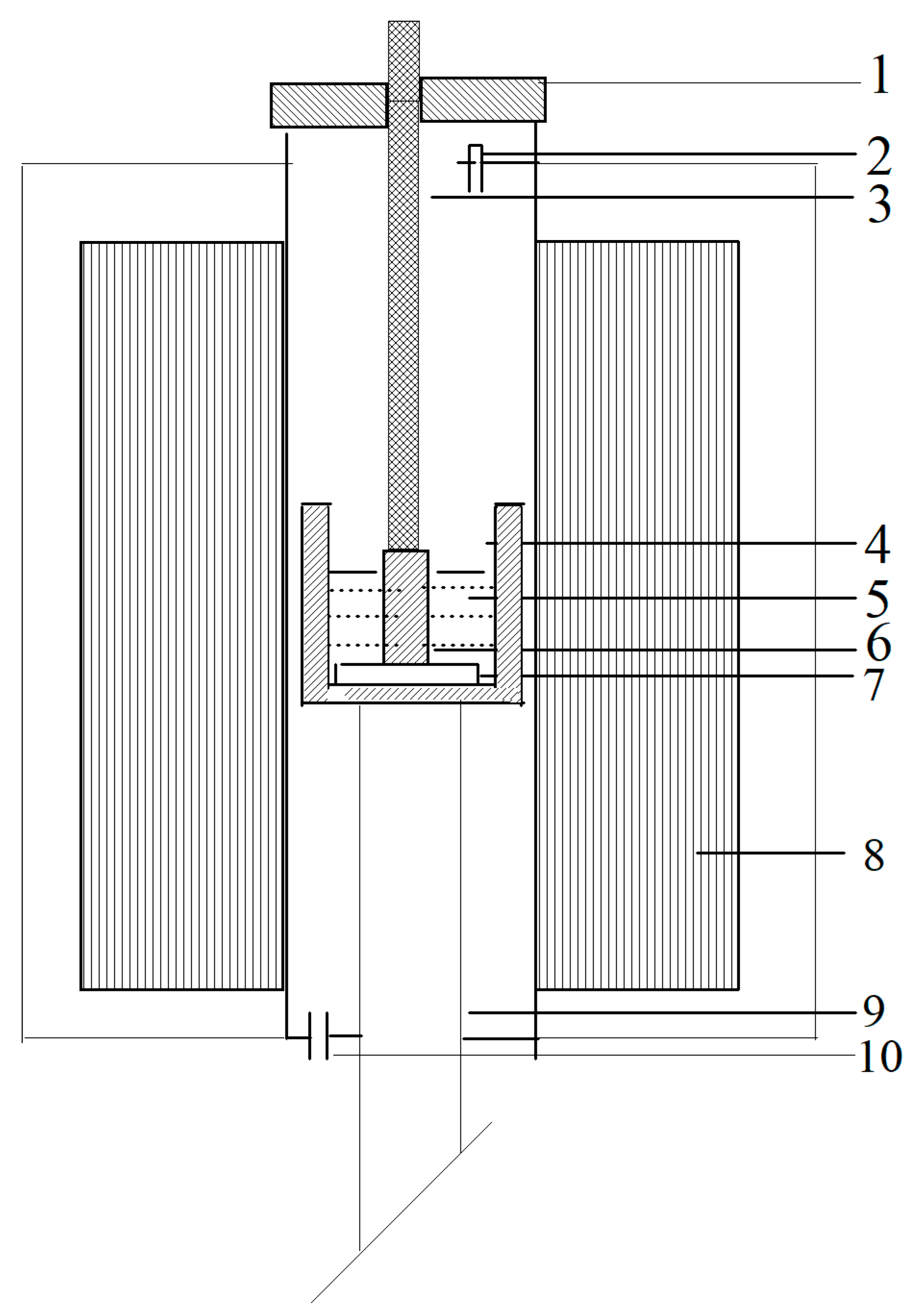
Figure 2.
Sodium expansion of the semigraphtic cathode sample at the two values of current density with various testing times (a) 20 min (b) 120 min.
Figure 2.
Sodium expansion of the semigraphtic cathode sample at the two values of current density with various testing times (a) 20 min (b) 120 min.

Figure 3.
HRTEM image of carbon cathodes at testing 20 min with various current densities (a) 0.45 A/cm2 (b) 0.7 A/cm2.
Figure 3.
HRTEM image of carbon cathodes at testing 20 min with various current densities (a) 0.45 A/cm2 (b) 0.7 A/cm2.
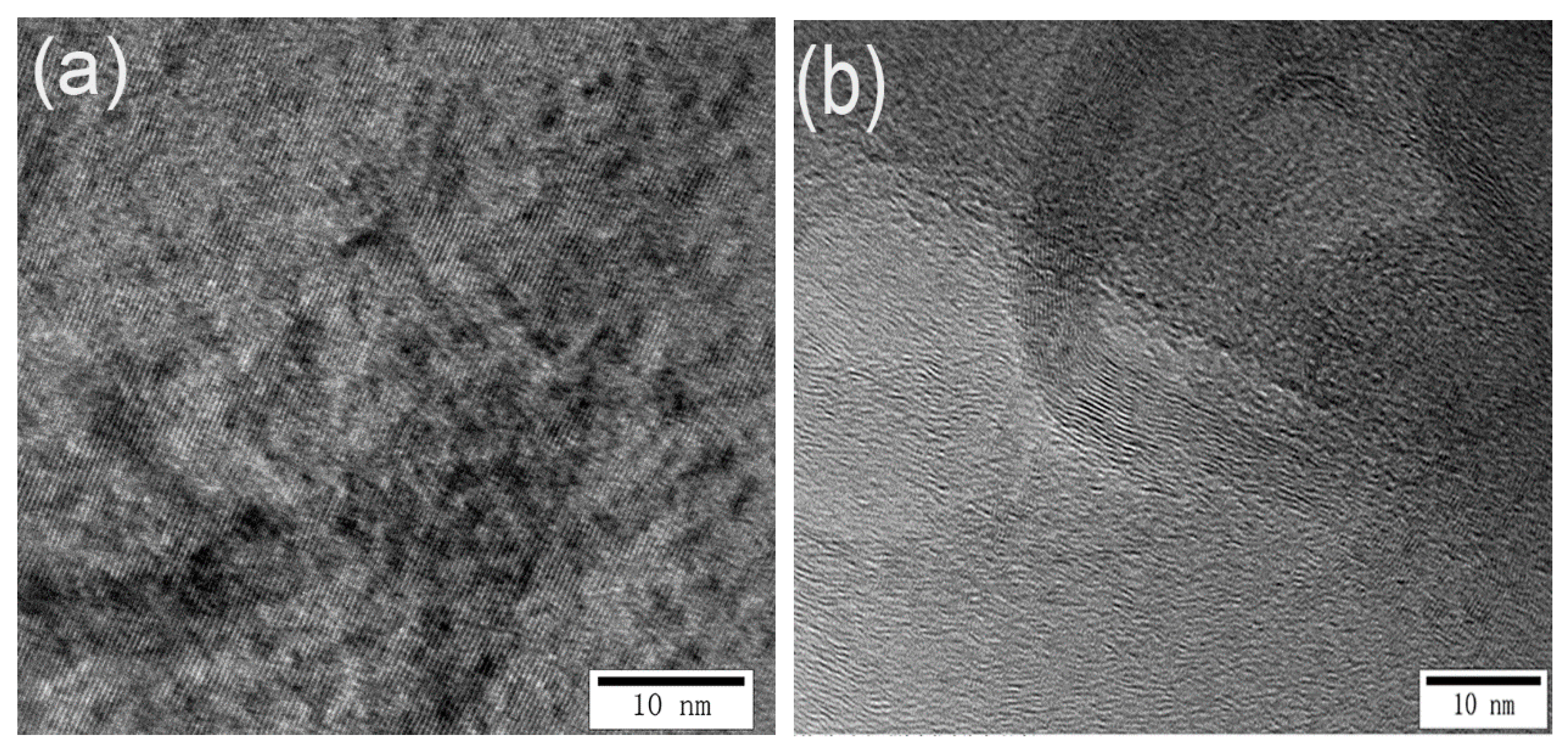
Figure 4.
Microstructures of the carbon cathode at testing time 120 min with a cathode current density of 0.7 A/cm2 (a) and (d) TEM image (b) and (c) HRTEM image.
Figure 4.
Microstructures of the carbon cathode at testing time 120 min with a cathode current density of 0.7 A/cm2 (a) and (d) TEM image (b) and (c) HRTEM image.


Figure 5.
SEM images of fractured surfaces of carbon cathodes at testing 120 min with various current densities (a) 0.45 A/cm2 (b) 0.7 A/cm2.
Figure 5.
SEM images of fractured surfaces of carbon cathodes at testing 120 min with various current densities (a) 0.45 A/cm2 (b) 0.7 A/cm2.

© 2020 by the authors. Licensee MDPI, Basel, Switzerland. This article is an open access article distributed under the terms and conditions of the Creative Commons Attribution (CC BY) license (http://creativecommons.org/licenses/by/4.0/).
Share and Cite
MDPI and ACS Style
Wang, W.; Sun, K. Influence of Current Density on the Microstructure of Carbon-Based Cathode Materials during Aluminum Electrolysis. Appl. Sci. 2020, 10, 2228. https://doi.org/10.3390/app10072228
AMA Style
Wang W, Sun K. Influence of Current Density on the Microstructure of Carbon-Based Cathode Materials during Aluminum Electrolysis. Applied Sciences. 2020; 10(7):2228. https://doi.org/10.3390/app10072228
Chicago/Turabian StyleWang, Wei, and Kai Sun. 2020. "Influence of Current Density on the Microstructure of Carbon-Based Cathode Materials during Aluminum Electrolysis" Applied Sciences 10, no. 7: 2228. https://doi.org/10.3390/app10072228
Note that from the first issue of 2016, this journal uses article numbers instead of page numbers. See further details here.