Detecting and Solving Tube Entanglement in Bin Picking Operations


1
Faculty of Engineering, University of Porto (FEUP), 4200-465 Porto, Portugal
2
Institute for Systems and Computer Engineering, Technology and Science (INESC TEC), 4200-465 Porto, Portugal
*
Author to whom correspondence should be addressed.
Appl. Sci. 2020, 10(7), 2264; https://doi.org/10.3390/app10072264
Submission received: 7 March 2020
/
Revised: 19 March 2020
/
Accepted: 19 March 2020
/
Published: 26 March 2020
Abstract
:Featured Application
The robotic bin picking solution presented in this work serves as a stepping stone towards the development of cost-effective, scalable systems for handling entangled objects. This study and its experiments focused on tube-shaped objects, which have a widespread presence in the industry.
Abstract
Manufacturing and production industries are increasingly turning to robots to carry out repetitive picking operations in an efficient manner. This paper focuses on tackling the novel challenge of automating the bin picking process for entangled objects, for which there is very little research. The chosen case study are sets of freely curved tubes, which are prone to occlusions and entanglement. The proposed algorithm builds a representation of the tubes as an ordered list of cylinders and joints using a point cloud acquired by a 3D scanner. This representation enables the detection of occlusions in the tubes. The solution also performs grasp planning and motion planning, by evaluating post-grasp trajectories via simulation using Gazebo and the ODE physics engine. A force/torque sensor is used to determine how many items were picked by a robot gripper and in which direction it should rotate to solve cases of entanglement. Real-life experiments with sets of PVC tubes and rubber radiator hoses showed that the robot was able to pick a single tube on the first try with success rates of 99% and 93%, respectively. This study indicates that using simulation for motion planning is a promising solution to deal with entangled objects.
1. Introduction
One problem faced by many industries is bin picking, where the goal consists of removing an item from a container with an open lid for further manipulation [1]. In most picking scenarios, the objects are arranged in a random fashion. Despite the broad body of research on bin picking, very few works dealt with the specific case of entangled objects. Handling entangled objects is all the more challenging as multiple objects may be inadvertently picked at once, rather than a single one, which can cause disruptions in industrial lines. In a recent publication by Matsumura et al. [2], they claimed to be the first ones to present practical experiments of picking entangled objects from a pile.
This research focuses on the case of tube-shaped objects, which are very common in manufacturing and production systems. Examples include refrigeration tubes in the automotive and aircraft industries, water pipes for plumbing installations and heat pipes in civil engineering. In many of these use cases, the tubes contain multiple curvatures along their length. Due to the widespread presence of curved tubes in the industry, there is a great economic interest in automating the bin picking task for this sort of objects.
This paper aims to present further advancements of the research regarding bin picking of entangled tube-shaped objects, by focusing on an industrial-inspired case study with radiator hoses from a vehicle’s engine. Previously, a perception algorithm was developed to create a geometric model of the tubes from an input point cloud captured by a 3D scanner [3]. This article expands on the modeling algorithm by presenting a motion and grasp planning algorithm that allows a two-fingered gripper to pick, one-by-one, a set of freely curved tubes randomly arranged in a pile. Trajectory synthesis is performed using several heuristics on the tubes’ models and the Gazebo simulator is used to test each trajectory and evaluate how likely it is to lead to a case of entanglement. Grasp planning is then performed using the tubes’ models and the results of trajectory planning. An efficient resolution method from cases of entanglement using a force/torque sensor is also presented. The proposed solution assumes that all tubes have the same radius and approximately equal mass, which is acceptable in most bin picking scenarios. Finally, this paper intends to formalize key concepts for modeling and handling tube-shaped objects in robotic picking scenarios.
The remainder of this manuscript is organized as follows. Section 2 presents relevant state-of-the-art research regarding bin picking. Section 3 details the complete approach used to perform bin picking on entangled tubes. It begins by providing a description of the aforementioned tube modeling technique. It then presents the motion planning, grasp planning, and entanglement resolution algorithms. Section 4 presents the experiments to evaluate the solution’s performance and discusses the results. Finally, Section 5 summarizes the research’s contributions and provides several lines for future research.
2. Related Work
Three of the more complex tasks in bin picking are grasp planning, motion planning, and failure detection.
Grasp planning aims to find a collision-free configuration for the robotic gripper that allows it to pick-up an object. Common parameters for this configuration include the grasping point on the object, the approach vector and the gripper’s orientation [4]. Grasp planning approaches are typically divided into a synthesis and analysis phase, where grasp configurations are generated and evaluated, respectively [5]. Most of the earlier works on grasp planning present analytical approaches, which aim to find grasps that optimize certain physical properties such as force-closure (where the grasp is resilient against external wrenches applied on the object being picked) or stability [6]. However, these approaches typically have the disadvantages of requiring accurate geometric models for the objects, having a high computational cost and few of them taking into account the constraints of the task at hand [7]. Nowadays, most researchers use empirical (or data-driven) methods to avoid a complex mathematical formulation of the problem by relying on prior knowledge. Empirical methods include learning-based techniques, which rely on previously acquired knowledge, and heuristic techniques, which use directly a representation of the scene. Matsumura et al. used depth images to compute a set of grasp candidates and trained a Convolutional Neural Network (CNN) using simulated examples to determine if grasping a given candidate and applying a lifting motion leads to entanglement [2]. To the best of the authors’ knowledge, this is the only other paper that explicitly deals with random bin picking of entangled objects. Heuristic methods do not need previous training and instead require parameter tuning. They also have the advantage of allowing users to more easily understand why a given decision was made. Miller et al. modeled the objects as a set of primitives (namely cylinders) and used a system of rules to define a set of grasping configurations, which take into account the geometry of the robot gripper and arm [8]. Wong et al. resorted to simple metrics for grasp evaluation such as the object’s proximity of the nearest object and determined the best objects to be picked before finding the most suitable grasps [9]. These contributions inspired the grasp planning solution of this manuscript, which also uses empirical methods and heuristics for grasp synthesis and evaluation.
Motion planning is used to determine a trajectory for the gripper, namely after grasping an object. Most of the research focuses on the particular case of finding a trajectory that avoids the gripper and the grasped object from colliding with the environment [10,11,12]. Planning algorithms include exploring the gripper configuration space (or one of its sub-spaces) with random sampling or using optimization techniques to minimize an objective function subject to equality and inequality constraints (such as keeping the gripper horizontal or preventing each of the robot arm’s joints from exceeding a certain velocity). However, in the problem at hand, due to tube entanglement, in many cases, collision is unavoidable and the objects’ pose may change as a certain tube is grasped, which must be taken into consideration when determining if a trajectory leads to multiple tubes being picked. Thus, this article proposes an alternative solution that involves evaluating trajectories using the Gazebo physics engine [13].
Failure detection is crucial in bin picking operations. If an item falls outside a robot’s working area, it may compromise the following steps in an assembly line. For this reason, companies spend much money on regular quality checks for their products and manufacturing pipelines. Force/torque sensors have been used several times to detect if pick-and-place operations were successful [14,15,16]. Moreira et al. focused on picking a set of entangled flexible tubes from a vehicle’s air conditioning system [15]. They assumed that grasp and motion planning routines already existed and that the mass of the tubes was known. By using the data from a six-axis force/torque sensor coupled with machine learning algorithms, they determined if the tube slipped after being grasped. Kanoulas et al. proposed a key strategy in their algorithm which is also used in this paper: if the force readings lie outside the expected range, the robot releases the object being grasped [17]. Costanzo et al. presented the concept of manipulating a grasped object using force feedback [18]. In their study, they used force/tactile sensors to adjust a parallel-jaw gripper’s force so that it could rotate around its axis whilst maintaining the object’s orientation. In this paper, rather than adjusting the closing force, torque feedback is used to determine the gripper’s axis of rotation so that non-grasped tubes that were inadvertently lifted are dropped back in the bin.
3. Bin Picking Algorithm
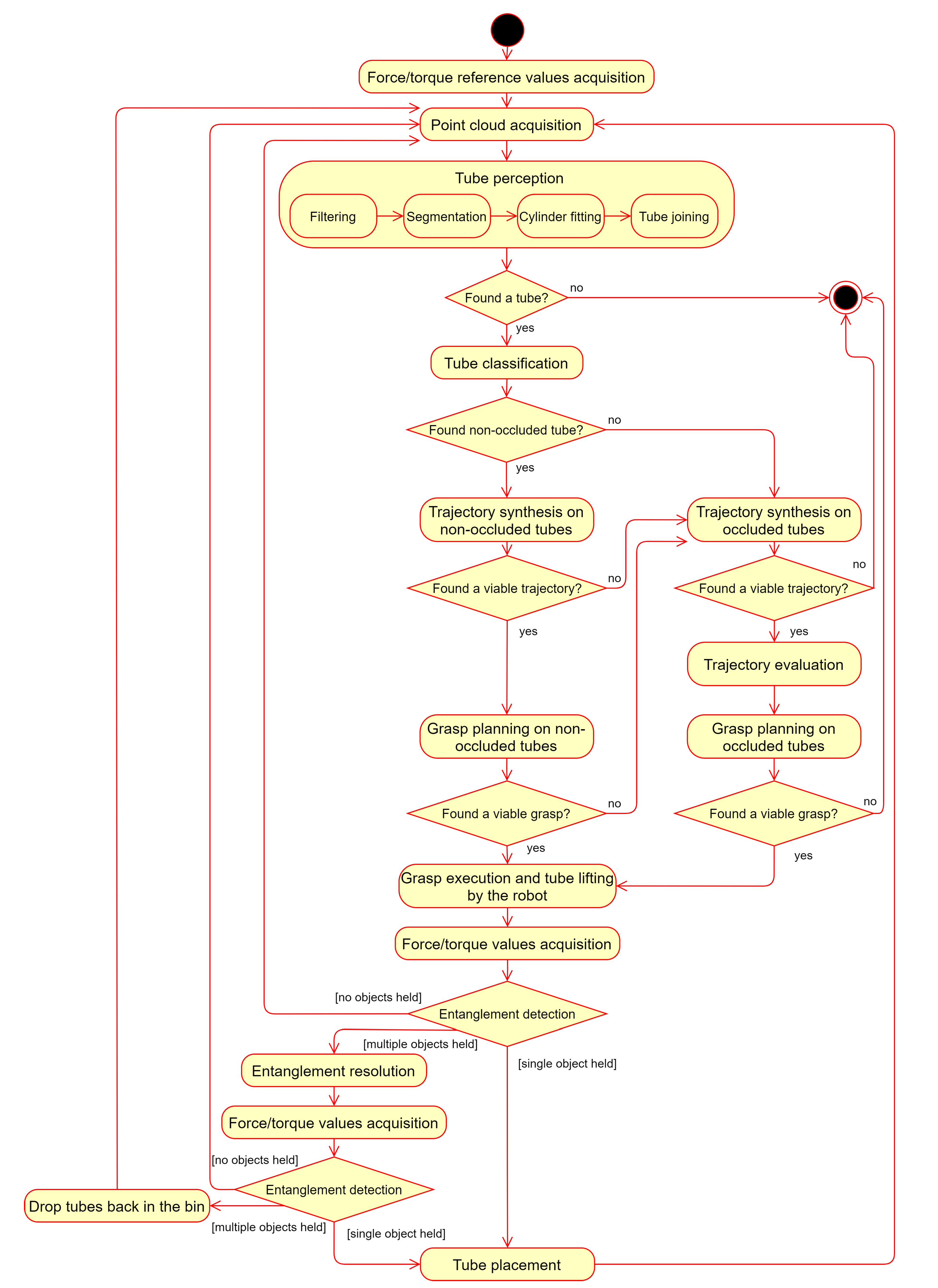
Figure 1 provides an overview of the different phases of the algorithm for picking entangled tubes. The ultimate goal of this solution is to allow a robotic arm to carry a single tube from the bin to the destination area.
The following subsections detail each phase of the algorithm.
3.1. Tube Modeling
The first phase consists of creating a model for each tube that is present in the bin. This phase uses as input a point cloud of the scene captured by a 3D scanner. These models are used in the subsequent phases to plan the robot’s trajectory and grasping pose. The modeling phase assumes that the tube radius is known and, optionally, an upper bound for the tube’s length may be provided.
Before presenting the main steps for the modeling, it is important to define some keywords that are used in the rest of the article.
Definition 1.
A real-life tube corresponds to a tube that is actually present in the bin.
Definition 2.
A virtual tube corresponds to a tube that was created during the modeling phase. It consists of an ordered list of cylinders and joints.
If the modeling is performed correctly, then there is a one-to-one mapping between the real-life and virtual tubes.
Definition 3.
An endpoint of a cylinder is a three-dimensional point at an intersection between the cylinder’s central axis and one of its bases. Each cylinder of a virtual tube has two endpoints.
Definition 4.
A joint is an entity that connects two consecutive cylinders of a virtual tube by their closest endpoints.
Definition 5.
An endpoint of a virtual tube
is an endpoint of one of its cylinders that is not connected to any other endpoint by a joint. Each virtual tube has two endpoints.
Definition 6.
The length of a virtual tube
is the sum of the combined length of its cylinders and joints (whose length is the distance between its endpoints).
The four steps of this phase are: filtering, segmentation, cylinder fitting, and tube joining [3].
During the filtering step, all of the cloud points that do not belong to any of the tubes are removed. In addition, the cloud is downsampled randomly to a certain amount of points so that the next steps are performed more efficiently.
The segmentation step aims to cluster the point cloud into disjoint piece-wise smooth regions. This is performed using a region-growing algorithm based on the surface normals and curvatures. The normals are estimated using a least-square method that fits a tangent plane to each point using the covariance matrix formed by the neighboring points from the raw point cloud [19]. The curvature of each point is computed using the eigenvalues of this matrix.
Definition 7.
A segment
is a subset of the filtered point cloud where the surface normal varies continuously. It corresponds to one of the clusters given by the segmentation step.
The cylinder fitting step processes each segment independently. For each segment, the Random Sample Consensus (RANSAC) method is repeatedly used to fit a cylinder to a section of it. A virtual tube is created for each cylinder. The outliers of one call to RANSAC are used as input in the next call for the same segment, until the number of outliers is too low to form a new cylinder. The result of this step is a set of tubes composed of a single cylinder and no joints.
Finally, the tube joining step aims to combine smaller tubes into longer virtual tubes. Whenever two tubes are combined, a new joint is created between the closest endpoints of both tubes. To perform this step, all pairs of endpoints of distinct virtual tubes are considered and a cost function that accounts for their Euclidean and angular distances is computed. Then, each pair is processed in ascending order of cost and the virtual tubes to which each of the endpoints belongs are combined if four conditions are satisfied:
- The cylinder endpoints still belong to distinct tubes.
- The pair’s Euclidean and angular distances are both below a certain threshold.
- There is no visible gap between both endpoints on the acquired point cloud’s representation as a depth image, from the sensor’s point of view (visibility constraint). This was implemented by finding the midpoint of both endpoint projections on the depth image and determining if there is a pixel in a small neighborhood around this midpoint that has less depth (i.e., is closer to the sensor) than the maximum depth among both endpoints.
- The length of the combined tube is below a certain optional maximum threshold (length constraint).
Figure 2 illustrates the tube modeling phase for two sets of tubes. In the images for the tube joining phase, the cylinders of each tube have different colors and the joints are represented as colored lines connecting the cylinders. The green and red lines represent occluded and non-occluded joints, respectively. Each cone represents an endpoint.
3.2. Tube Classification
This phase aims to select the tubes that have the highest potential of being picked without facing any issues of entanglement, where other tubes are also brought up by the robot arm when it performs the lifting motion.
Firstly, if a value is provided for the tubes’ length, then all the virtual tubes whose length is below a certain minimum threshold (which subtracts from the expected length a tolerance value) are immediately discarded since they correspond to incomplete models of real-life tubes. The value of a virtual tube’s length is typically smaller than the corresponding real-life tube’s length (due to the approximation of the curve as a set of segments). This should be taken into account when defining the minimum acceptability threshold.
Secondly, the number of occlusions for each tube is counted from the sensor’s point of view. Since the sensor’s line of sight is vertical, this provides a computationally efficient manner of detecting overlaps between tubes. Occlusions can only occur in joints since cylinders correspond to approximation of continuous, visible portions of a tube.
Definition 8.
An occluded joint
is a joint for which the segments used to create both of its connected cylinders are different.
At the end of this phase, two disjoint sets of tubes are created: the non-occluded tubes, the weakly-occluded tubes and the strongly-occluded tubes. In this paper, only the non-occluded and weakly-occluded tubes are considered as candidates to be picked.
Definition 9.
A non-occluded tube is a virtual tube with no occluded joints.
Definition 10.
A weakly-occluded tube is a virtual tube with a single occluded joint. The linked list of cylinders in an occluded tube is partitioned into two sections by the occluded joint.
Definition 11.
A strongly-occluded tube is a virtual tube with two or more occluded joints.
3.3. Trajectory Planning
The goal of this phase is to generate and evaluate a set of trajectories for the robotic gripper to follow after grasping a tube. A cost is computed for each trajectory which reflects an estimate of how likely executing it will lead to a case of entanglement. This cost is computed via simulation.
Definition 12.
A trajectory of a virtual tube is defined by an ordered list of poses, known as waypoints, that represent translations and rotations of the tube relative to its initial position in the bin. The first waypoint of any trajectory is always a relative pose with no translation or rotation.
In this article, the waypoints are simplified to only contain a relative position, since all trajectories are a set of translations.
3.3.1. Trajectory Synthesis
Two sorts of trajectories are considered: an upwards trajectory (where only the z component of the gripper’s position is affected) and an escape trajectory. This second trajectory begins by performing a small upwards motion, followed by a movement along a line on the x and y axes to try to move the tube so that it is no longer occluded, and ends with another larger upwards trajectory.
If the set of non-occluded tubes is not empty, then an upwards trajectory is created for each of them with a cost of 0, and the algorithm moves on to the grasp planning phase directly. Therefore, the simulator is not used, as it is assumed that since these tubes do not have any other object on top of them, as long as a suitable grasping point is chosen, lifting them should not lead to a situation of entanglement. Avoiding using the simulator for these simpler cases has the advantage of considerably shortening the algorithm’s processing time.
If no suitable grasps are found for any of the non-occluded tubes, then the weakly-occluded tubes are considered. For each of these tubes, three trajectories are generated: the upwards trajectory and two escape trajectories that try to free the tube from the occluding object by performing a lateral movement in both directions of the escape line, defined below.
Definition 13.
The escape line of an occluded tube is the orthogonal projection of the line that passes through both of the occluded joint’s endpoints on the xOy plane.
The distance along the escape line that the gripper moves in one of the directions is given by Equation (1), which is a sum of a variable term, , and a constant term, .
Let be one of the two endpoints of the occluded joint, the set of cylinder endpoints on the same section as , and the projection of point P on the escape line. The variable term (Equation (2)) is the distance between the occlusion and the farthest endpoint projected on the escape line. It varies according to which direction the tube is moved.
The constant term is a predefined distance that significantly increases the chances of solving the entanglement by accounting for possible inaccuracies during the tube modeling. It should be at least as large as three times the tube’s radius. This is due to the possibility of the length of an occlusion being as large as the occluding tube’s diameter. In addition, the farthest endpoint may not be the farthest point of the section to the occlusion, which occurs when the axis of the cylinder containing the farthest endpoint is not parallel to the escape line.
Figure 3 provides a visual aid for the escape line and distances.
To prevent the tube from colliding with the bin’s walls, it is checked if the bounding box of the virtual tube (in the x and y axes) after applying the horizontal translation of the escape trajectory intersects a predefined rectangular safety zone, which is smaller than the bin’s boundaries. If this intersection occurs, then the escape distance is shortened to be the largest distance along the escape line for which such a collision does not occur.
3.3.2. Trajectory Evaluation
The synthesized trajectories alongside the tubes’ geometric models are then sent to Gazebo. Each trajectory contains an identifier of the tube to be moved and an ordered list of waypoints.
In the simulated environment, the tubes are also modeled as a set of cylinders with the same lengths, radii, and poses as those computed during the tube modeling phase. The only differences are that cylinders are created for each joint to connect each pair of endpoints and a sphere with a radius equal to the tube’s radius is added to each endpoint involved in a joint. These two changes prevent the tubes from having gaps. To reduce the number of objects in the simulated environment, and thus decrease the computational effort, none of the models for the robot’s parts are added to the simulated environment. Figure 4 presents some examples of simulated tubes in Gazebo.
Before spawning all of the tubes in the simulation world, a small amount of time is given to allow all objects to reach a stable state, where they are no longer moving due to gravity and contact forces between them. Before testing each trajectory, the world is reset back to this same stable state.
For each trajectory, the associated tube is moved at a constant velocity along each segment between consecutive waypoints until the last endpoint is reached. The velocity in the simulation environment is the same as the gripper’s during the motion execution. The poses of the other tubes are computed at each time step using the physics engine. After each trajectory is concluded, the displacement of each tube is measured as the distance between the positions of its center of mass after following the trajectory and on the stable state. The cost for each trajectory corresponds to the sum of the displacements of all tubes, with the exception the one that was intentionally moved. This cost function enables the detection of cases where other tubes were unintentionally lifted and is also sensitive to trajectories that cause too much disruption in the bin.
3.4. Grasp Planning
During the grasp planning phase, a set of grasps is created for each trajectory. This phase occurs after the trajectory planning phase since it is assumed that the tubes are rigid enough so their shape is not affected by the location of the grasping point. If the tubes were more flexible, then the trajectory planning should take into account the grasp’s configuration.
Definition 14.
A grasp for a virtual tube is defined by the 3D point , known as the grasping point, which is the gripper’s tool center point (TCP) position when it grasps the object. In addition, a grasp is associated with an orientation for the gripper, the fingertip positions, an approximation vector it follows before grasping the tube, and a trajectory it follows after grasping.
3.4.1. Grasp Synthesis
The grasping point is always defined to be along one of tube’s cylinder axis. The gripper is always set to be completely vertical, and thus only the yaw is adjusted so that the planes defined by the contact points between the fingertips and the tube’s surface are always normal to the surface’s normal vector. The approach vector is also always set to be vertical.
For each trajectory, the grasping points are created by traversing the tube’s cylinders and creating points at a constant distance between them and at a minimum distance from the cylinders’ bases. Figure 5 shows examples of the grasping points generated for two sets of tubes. The grasping points are represented by a white sphere. In Figure 5b, the points are only computed for the non-occluded tubes, which are colored in green. The yellow tubes are weakly-occluded, while the red ones are strongly-occluded.
Three tests are performed to verify if a grasp is viable. Non-viable grasps are rejected, and not taken into account for the grasp evaluation.
Firstly, to determine if the gripper has a risk of colliding with either another tube or the bin’s boundaries when executing a grasp, a simplified model of the parallel jaw gripper as two oriented bounding boxes with a gap between them slightly larger than a tube’s radius is used. The bounding boxes are positioned and oriented according to the gripper’s pose as it is about to grasp the tube. The raw point cloud (i.e., without any filters applied to it) is used and the grasp is rejected if the number of points within the combined volume of both bounding boxes surpasses a certain threshold.
Secondly, to prevent the gripper from overstepping its working area, it is checked if, for each waypoint of the trajectory, the point obtained by adding the waypoint’s translation to the grasping point lies inside a predefined bounding volume. If any of these points is outside of this zone, then the grasp is rejected.
Finally, grasps associated with an escape trajectory (and thus a weakly-occluded tube) are rejected if the grasping point lies in the section of the virtual tube that is expected to pass under the occluding tube. This prevents the gripper from colliding and dragging the occluding tube when following the trajectory. In Figure 3, escape trajectories that move the occluded tube to the upper-left corner can only have grasps whose points belong to the three cylinders on the left section.
3.4.2. Grasp Evaluation
Each grasp is evaluated by associating it a cost using Equation (3), which reflects how likely the grasp will lead to an entanglement, where multiple tubes are picked at once. This cost is normalized to scale the range and consists of a linear combination of three normalized costs: the height cost, , the center cost, , and the trajectory cost, . The combined sum of the weights of these costs (, , and ) is equal to 1.
The height cost (Equation (4)) corresponds to the height of the grasping point relative to the heights of the tubes. The variable is the z coordinate of the highest point of the filtered point cloud, which is obtained during the first step of the modeling phase and only contains points belonging to the tubes. It is assumed that the equation for the bin’s bottom plane is .
The center cost (Equation (5)) reflects how far the grasping point is from the center of the tube along its curve length L. The rationale of this cost is that the farther the tube is grasped from its center, the higher the torque that will be generated, which can lead to more unstable grasps.
The trajectory cost (Equation (6)) corresponds to an estimate provided by Gazebo during the trajectory analysis of how much the other tubes are moved when a given tube is grasped. This cost has the same value for all the grasps on the same tube, and is equal to 0.0 if the tube is non-occluded (as their trajectories do not require simulation). The displacement is normalized using a maximum displacement value , above which it is considered that any trajectory has the same (high) odds of leading to a case of entanglement.
3.5. Entanglement Detection
Before beginning the whole pick and place process, it is stored the sensor measurement for the force on the z+ axis (pointing upwards) being exerted on the flange when no object is being held. This measurement is referred to as the reference value for the force, .
After performing the grasping and lifting actions, the current force value on the z axis, , is measured to determine how many tubes were picked. This requires prior knowledge of the tubes’ mass and assumes all tubes have approximately the same mass. There are three possible cases: no object is being held, a single object is held and multiple objects are being held. These three cases are distinguished by computing the expected additional force exerted on the flange when a single tube is being held (which corresponds to the tube’s weight), as presented in Algorithm 1.
| Algorithm 1 Entanglement detection algorithm. |
Input: - Reference z force (N) - Actual z force (N) - Tube mass (kg) - Tolerance value for the force (N) Output: - Either , or
|
When a single object is detected, the robot follows the default routine and proceeds to placing the tube on the destination area. If no object is detected, the robot restarts the bin picking process, and rescans the scene. Finally, if multiple objects are detected, a resolution routine is performed in an attempt to solve the entanglement problem, as explained in Section 3.6.
3.6. Entanglement Resolution
Similar to the reference value for the z force, before scanning the bin for the first time, the sensor measurements for the torques exerted on the x and y axes are stored ( and respectively).
When the z force is too low, which corresponds to a case of entanglement (multiple tubes were picked), the torque sensor measures the current values for the torque in the x and y axes, and , and the torque difference vector is computed according to Equation (7).
This torque vector defines the axis around which the gripper and its payload would rotate if it was not attached to the robot arm, as shown in Figure 6.
The gripper rotates around its tip in this axis and in the positive direction to try to make the undesired tubes drop back into the bin. After applying the rotation, the z force is once again measured to detect if the entanglement is still present. If so, the gripper drops the tubes back in the picking bin. If not, then the process proceeds normally and the single tube is placed on the destination.
3.7. Tube Placement
When placing tubes on the destination area, it is important for them to have a consistent orientation so that they can be further processed more easily.
During this phase, it is assumed the gripper is holding a single tube. The points belonging to the tube are used to compute the object’s principal axes using PCA (Principal Component Analysis), by performing eigendecomposition on the points’ normalized covariance matrix [20]. The principal component with the highest eigenvalue provides a reliable estimate of the tube’s orientation (i.e., if the tube is a perfect cylinder, then the first principal component will correspond to the cylinder’s axis). To ensure that the tube is placed with the correct orientation, the gripper performs a rotation to align the principal component with a predefined axis describing the desired orientation.
Optionally, to prevent the gripper from performing dangerous rotations, the principal direction vector can be projected in the xOy plane so that the alignment rotation only contains a yaw component.
Figure 7 presents an example of a coordinate frame that reflects the tube’s orientation. The unit vector for the x-axis (in red), , is oriented according to the principal direction vector’s projection on the xOy plane while the unit vector for the z-axis (in blue), , is equal to . The vector for the y-axis (in green) is simply equal to . The tube is placed with a movement for the gripper that allows this coordinate frame to be aligned with a predefined frame in the destination area.
4. Experiments
4.1. Overview
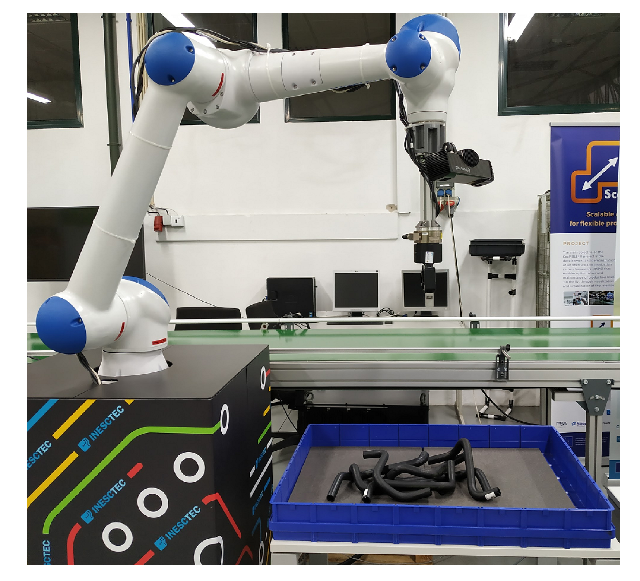
Figure 8 provides an overview of the arrangement used to conduct the experiments. A Yaskawa Motoman HC10 robot arm was used. It has a reach of 1200 mm and can handle payloads of up to 10 kg with a repeatability of 0.1 mm. A Robotiq 2F-85 gripper was attached to its flange, alongside a Photoneo PhoXi 3D Scanner S and an ATI Gamma SI-65-5 force/torque sensor, as shown in Figure 9. The 3D scanner has a range from 384 to 520 mm and a resolution of 3.2 million points. At the optimal distance (442 mm), it has a scanning area of 360 mm × 286 mm and an accuracy of 0.05 mm. The force/torque sensor is able to sense forces of up to 200 N in the z direction, with a resolution of 1/40 N. It can also detect torques of up to 5 N·m in each direction, with a resolution of 10/13,333 N·m.
The tubes to be picked were placed in a bin, whose dimensions are approximately 77 cm (length) × 58 cm (width) × 9 cm (height). Two sets of seven tubes were used (Figure 10). Their properties are summarized in Table 1.
The tubes on Set A are the same as those used on the conference article focused on the tube modeling phase [3]. They are straight plumbing pipes that were manually bent to have different shapes. They correspond to a simpler test case since their material has less friction, and thus the tubes that are on top of the one being picked tend to slide back into the bin.
The tubes from Set B are radiator hoses from a Fiat Tipo engine. These tubes are more prone to entanglement since their curves are not planar and their rubber surface provides more friction.
For each set of tubes, 20 rounds of bin picking were performed, where a round consists of manually placing the tubes in a random arrangement in the bin and then making the robot follow the whole picking pipeline of Section 3 to empty the bin by picking the tubes one-by-one.
Table 2 presents the parameter values used when conducting the experiments.
4.2. Results
The Entangled Tubes Bin Picking dataset from the authors’ previous research [3] was expanded to include the files of all the point clouds acquired by the 3D scanner during the experiments. The dataset is available at https://github.com/GoncaloLeao/Entangled-Tubes-Bin-Picking-Dataset. This repository also includes a link to raw footage of all the experiments.
Table 3 presents the solution’s success rate for emptying the bin. The six unsuccessful cases were due to tubes that moved to the corners of the bin, where the scanner could not detect them, causing the round to end prematurely. The sensor could not scan the bin from a higher position since the cloud points it acquired had too much noise due to the scanning distance exceeding by a large amount the optimal range. A smaller bin was not used so that the robot could freely experiment escape trajectories without the risk of either the gripper or the grasped tube colliding with the bin’s walls. As future work, multiple scans of the bin from different positions can be acquired or a sensor with a larger working area can be used.
In all of the rounds, when all of the tubes were brought to the destination area, the robot was able to infer the bin was empty by the latest acquired point cloud and end the picking process.
There were no cases in which multiple tubes were carried to the destination area or where a tube fell outside the bin. Therefore, every time a single tube was lifted from the bin, it always reached the destination area.
In the results and discussion that follow, let a picked tube be a real-life tube that was successfully placed in the destination area in a given round, possibly after multiple attempts (the last one being the successful attempt or successful pick).
Table 4 shows the percentage of picked tubes that were successfully placed on the first try. The high overall success rates alongside the significant amount of picked tubes indicate that the proposed algorithm had a very positive performance for both tube sets. As expected, the success rate for Set B is slightly smaller than for Set A since the former tubes’ geometry and material made them more prone to entanglement. In Set B, the lowest success rate corresponds to cases where there were seven tubes in the bin, which is likely due to the presence of more complex tube arrangements. Conversely, in both sets, there is a 100% success rate of picking tubes at the first attempt when the bin only contains one or two objects. The results seem to indicate that the success rate does not increase at a constant rate as the number of remaining tubes decreases. The authors speculate this is due to the algorithm giving preference to picking the non-occluded tubes first, which postpones solving entanglement issues. This property may be advantageous since the contact forces exerted by the tubes that are picked first may move the other ones in such a way that it is easier to pick them later on.
Table 5 indicates how often the robot resorted to the simulator for trajectory evaluation (i.e., how often all of the tubes had occlusions) when attempting to pick a tube. It also shows how often each type of trajectory was used to move the gripper after grasping. The simulator was used much more often with Set B since the tubes’ shape lead to more cases of occlusion. Most of the time, an upwards trajectory was preferred over the escape ones, which performed an additional lateral movement.
Interestingly, the trajectory simulator was only used on first attempts to pick a tube. As a result, during the second attempts, there was always at least one non-occluded tube in the pile. In addition, every single second attempt at picking a tube was successful, for both Sets A and B. This evidences that simply dropping the grasped tube back into the bin when it is entangled is a good strategy for bin picking.
Table 6 presents the success rate of the picking attempts which used the simulator. Unlike the previous tables, these rates were not presented in function of the number of tubes in the bin, as there were not enough examples for each amount. Set A had a success rate of 100% for both kinds of trajectories, which is most likely due to the PVC tubes’ surface allowing them to slip and fall back into the bin much more easily. The results from Set B show a very interesting result: the success rate for the escape trajectories is significantly higher than the one for the upwards trajectories. By combining the observations from the results in Table 5 and Table 6, one can conclude that it is harder to execute a useful escape trajectory than to simply lift a tube, but, when the former alternative is possible, it yields much better results. This conclusion suggests that having a wider variety of trajectories to choose from will increase this solution’s overall performance.
Figure 11 depicts a successful pick with an escape trajectory. In this example, neither the grasped tube nor the gripper touched any of the other tubes.
Table 7 shows how often the entanglement resolution phase was used. Since Set A had a 100% picking success rate with the simulator, this phase was never needed. For Set B, the rate is also quite low since the trajectory simulator had a moderately high success. The usage rate does not seem to vary significantly with the amount of tubes, which is coherent with the previous observation that this solution solves tougher cases of entanglement as late as possible during a round.
Table 8 presents the success rate of the entanglement resolution phase. The success rate for Set B was rather low, most likely due to one key observation that was made when the experiments were conducted: most of the time, a rotation of 45° was not enough to make the other tubes fall because the friction for the rubber material is too high. Higher angles were not attempted as they increased the chances of the tubes falling outside the bin. To increase the likelihood of solving the entanglement, a positive and negative rotation of 45° (or possibly more, with the appropriate setup) could be applied according to an axis contained in the xOy plane that is perpendicular to the torque vector . Furthermore, negative rotations could be experimented around the axis defined by this vector.
In none of the experiments was there a case where all of the tubes had two or more occlusions (strongly-occluded tubes). In these scenarios, one could experiment using the upwards trajectory and, as an alternative, a set of escape trajectories that take into account the properties of each occlusion. Then, the simulator could be used to evaluate the trajectories.
Table 9 presents the execution time of different phases of the algorithm considering all of the picking attempts (all cases), only the attempts that did not use the simulator (cases without simulation), and only the attempts that did use the simulator (cases with simulation). Total processing time is the time taken by the solution to perform all of the computations, including those of the tube modeling, motion planning, and grasp planning phases, as well as other operations, including the PCA computations of the tube placement step. Planning time is the combined time taken by the motion and grasp planning phases.
As shown in Table 9, using the simulator has a high impact on the total processing time. For future work, this time can be significantly reduced by speeding up the simulation by increasing the simulation step size. Since the focus of this research’s experiments was accuracy, the simulation was set to run with a maximum step size of 0.001 and an update rate of 1000 Hz, which results in the simulation time running approximately as fast as real time. Moreover, unlike previous experiments conducted by the authors for the modeling phase [3], the whole, unfiltered point cloud was used to estimate the surface normals and curvatures, to ensure optimal accuracy for the modeling phase. Previous experiments had shown that downsampling the cloud used for normal estimation reduces the modeling time to around 1 s, which would reduce the average total processing time to around 5 s and 7 s for Sets A and B, respectively, when all picking attempts are considered.
The total processing time for Set A is lower than for Set B when all test cases are considered. This is to be expected since the simulator is used much more often in Set B. However, both the modeling time and the total processing time without the simulator are lower in Set B than in Set A. One possible explanation is that this is due to the tubes in Set A having a larger radius (which increases the time needed to estimate the normals and curvatures since a point has more close-by neighbors) and length (which causes more grasping points to be generated since the cylinders are longer).
The large values for the standard deviation of the planning and total processing times for the cases with simulation, in comparison to those of the cases without simulation, show that there is a very high variability in the time needed for motion planning, possibly due to an equally high variability on the amount of trajectories to evaluate.
5. Conclusions
This paper proposes an algorithm for robotic bin picking of tube-shaped objects that handles occlusion and entanglement, for which there is little research, as well as a set of key definitions to tackle this challenge. The solution’s main steps are generating a model of the tubes via point cloud analysis to determine which objects are occluded, using a physics engine to simulate various trajectories for post-grasp movement and performing force/torque analysis to detect and solve cases of entanglement.
On 20 experiments conducted using seven rubber radiator hoses, the robot was able to completely empty the bin with a success rate of 80%, while successfully picking up tubes on the first try 93% of the time. The system resorted to simulation on 17% of the attempts with a success rate of 68%, thus illustrating that using a simulator to perform motion planning is a promising technique. Entanglement resolution was also useful and was used on 8% of the picks with a success rate of 27%. Therefore, this study shows that the proposed solution presents relevant contributions towards the development of accurate and efficient industrial systems capable of manipulating entangled objects.
The work presented in this paper opens several lines for further research. Firstly, other sorts of tubes, with different lengths, radii, and shapes could be used to perform tests with the solution presented in this article, to better ascertain its efficiency and limitations. Secondly, to increase the attractiveness of this solution for deployment in industrial settings, it is important to reduce the execution time, namely for the motion planning phase with the simulator. Experiments can be conducted to test how much the simulation can be sped up without causing instabilities (which may lead to cases of objects clipping). Thirdly, to increase the probability of successfully picking a single tube at a time, more types of trajectories could be generated. In particular, one could determine which tubes are occluding a given tube and compute an escape trajectory based on the formers’ spatial configuration. It should be noted that the amount of trajectory candidates should be kept reasonably low to prevent the cycle time from increasing significantly due to the time needed for evaluation via simulation. Finally, this solution could be extended to deal with objects that have a certain degree of flexibility, by configuring the physics engine used by the simulator and calibrating its parameters. This improvement would have a great impact in the robotics industry since very little research has been conducted regarding bin picking of flexible objects.
Author Contributions
Conceptualization, G.L., C.M.C., A.S., and G.V.; methodology, G.L., C.M.C., A.S., and G.V.; software, G.L.; validation, G.L.; formal analysis, G.L.; investigation, G.L.; resources, G.L., C.M.C., A.S., and G.V.; data curation, G.L.; writing—original draft preparation, G.L.; writing—review and editing, G.L., C.M.C., A.S., and G.V.; visualization, G.L.; supervision, C.M.C., A.S., and G.V.; project administration, G.L.; and funding acquisition, A.S. and G.V. All authors have read and agreed to the published version of the manuscript.
Funding
This work is financed by National Funds through the Portuguese funding agency, FCT - Fundação para a Ciência e a Tecnologia, within project UIDB/50014/2020.
Conflicts of Interest
The authors declare no conflict of interest. The funders had no role in the design of the study; in the collection, analyses, or interpretation of data; in the writing of the manuscript, or in the decision to publish the results.
References
- Alonso, M.; Izaguirre, A.; Graña, M. Current Research Trends in Robot Grasping and Bin Picking. In Proceedings of the International Joint Conference SOCO’18-CISIS’18-ICEUTE’18, San Sebastián, Spain, 6–8 June 2018; Springer: New York, NY, USA, 2019; Volume 771, pp. 367–376. [Google Scholar] [CrossRef]
- Matsumura, R.; Domae, Y.; Wan, W.; Harada, K. Learning Based Robotic Bin-picking for Potentially Tangled Objects. In Proceedings of the 2019 IEEE/RSJ International Conference on Intelligent Robots and Systems (IROS), Macau, China, 3–8 November 2019; IEEE: Piscataway, NJ, USA, 2019; pp. 7990–7997. [Google Scholar] [CrossRef]
- Leão, G.; Costa, C.M.; Sousa, A.; Veiga, G. Perception of Entangled Tubes for Automated Bin Picking. In Proceedings of the ROBOT 2019: Fourth Iberian Robotics Conference, Porto, Portugal, 20–22 November 2019; Springer: New York, NY, USA, 2019; pp. 619–631. [Google Scholar] [CrossRef]
- Bohg, J.; Morales, A.; Asfour, T.; Kragic, D. Data-Driven Grasp Synthesis—A Survey. IEEE Trans. Robot. 2013, 30, 289–309. [Google Scholar] [CrossRef] [Green Version]
- Haschke, R.; Steil, J.J.; Steuwer, I.; Ritter, H. Task-Oriented Quality Measures for Dextrous Grasping. In Proceedings of the 2005 International Symposium on Computational Intelligence in Robotics and Automation, Espoo, Finland, 27–30 June 2005; IEEE: Piscataway, NJ, USA, 2005; pp. 689–694. [Google Scholar] [CrossRef]
- Roa, M.A.; Suárez, R. Grasp quality measures: Review and performance. Auton. Robot. 2015, 38, 65–88. [Google Scholar] [CrossRef] [PubMed] [Green Version]
- Sahbani, A.; El-Khoury, S.; Bidaud, P. An overview of 3D object grasp synthesis algorithms. Robot. Auton. Syst. 2012, 60, 326–336. [Google Scholar] [CrossRef] [Green Version]
- Miller, A.T.; Knoop, S.; Christensen, H.I.; Allen, P.K. Automatic grasp planning using shape primitives. In Proceedings of the 2003 IEEE International Conference on Robotics and Automation (Cat. No.03CH37422), Taipei, Taiwan, 14–19 September 2003; IEEE: Piscataway, NJ, USA, 2003; pp. 1824–1829. [Google Scholar] [CrossRef] [Green Version]
- Wong, C.K.; Lim, P.P.K.; Clist, R.; Liu, R.S. Vision Strategies for Robotic Manipulation of Natural Objects. In Proceedings of the Australasian Conference on Robotics & Automation, Sydney, Australia, 2–4 December 2009. [Google Scholar]
- Ellekilde, L.P.; Petersen, H.G. Motion planning efficient trajectories for industrial bin-picking. Int. J. Robot. Res. 2013, 32, 991–1004. [Google Scholar] [CrossRef]
- Iversen, T.F.; Ellekilde, L.P. Benchmarking motion planning algorithms for bin-picking applications. Ind. Robot 2017, 44, 189–197. [Google Scholar] [CrossRef]
- Vonásek, V.; Vick, A.; Saska, M. Motion planning with motion primitives for industrial bin picking. In Proceedings of the IEEE International Conference on Emerging Technologies and Factory Automation (ETFA), Limassol, Cyprus, 12–15 September 2017; IEEE: Piscataway, NJ, USA, 2017; pp. 1–4. [Google Scholar] [CrossRef]
- Koenig, N.; Howard, A. Design and use paradigms for gazebo, an open-source multi-robot simulator. In Proceedings of the 2004 IEEE/RSJ International Conference on Intelligent Robots and Systems (IROS), Sendai, Japan, 28 September–2 October 2004; IEEE: Piscataway, NJ, USA, 2004; Volume 3, pp. 2149–2154. [Google Scholar] [CrossRef] [Green Version]
- Yanagihara, Y.; Kita, T. Parts-picking in disordered environment. In Proceedings of the IROS ’91:IEEE/RSJ International Workshop on Intelligent Robots and Systems ’91, Osaka, Japan, 3–5 November 1991; IEEE: Piscataway, NJ, USA, 1991; Volume 2, pp. 517–522. [Google Scholar] [CrossRef]
- Moreira, E.; Rocha, L.F.; Pinto, A.M.; Moreira, A.P.; Veiga, G. Assessment of Robotic Picking Operations Using a 6 Axis Force/Torque Sensor. IEEE Robot. Autom. Lett. 2016, 1, 768–775. [Google Scholar] [CrossRef]
- Chan, Y.; Yu, H.; Khurshid, R.P. Effects of Force-Torque and Tactile Haptic Modalities on Classifying the Success of Robot Manipulation Tasks. In Proceedings of the 2019 IEEE World Haptics Conference, WHC 2019, Tokyo, Japan, 9–12 July 2019; IEEE: Piscataway, NJ, USA, 2019; pp. 586–591. [Google Scholar] [CrossRef]
- Kanoulas, D.; Lee, J.; Caldwell, D.G.; Tsagarakis, N.G. Center-of-mass-based grasp pose adaptation using 3d range and force/torque sensing. Int. J. Humanoid Robot. 2018, 15. [Google Scholar] [CrossRef] [Green Version]
- Costanzo, M.; De Maria, G.; Natale, C. Two-Fingered In-Hand Object Handling Based on Force/Tactile Feedback. IEEE Trans. Robot. 2019, 36, 157–173. [Google Scholar] [CrossRef]
- Rusu, R.B. Semantic 3D Object Maps for Everyday Manipulation in Human Living Environments. KI-Künstliche Intell. 2010, 24, 345–348. [Google Scholar] [CrossRef] [Green Version]
- Liu, Y.S.; Ramani, K. Robust principal axes determination for point-based shapes using least median of squares. Comput. Aided Des. 2009, 41, 293–305. [Google Scholar] [CrossRef] [PubMed] [Green Version]
Figure 1.
UML activity diagram of the bin picking algorithm.

Figure 2.
Two examples of each step of the tube modeling phase.

Figure 3.
Visual representation of the escape line and distances for an occluded tube.

Figure 4.
Examples of sets of simulated tubes in Gazebo.

Figure 5.
Examples of grasping points on tubes.

Figure 6.
Visual representation of the torque vector.

Figure 7.
Example of the coordinate frame for a tube’s orientation.

Figure 8.
Setup overview.

Figure 9.
End-effectors attached to the flange.

Figure 10.
Sets of tubes used in the experiments.

Figure 11.
Successful escape trajectory example.


Table 1.
Main properties of the considered sets of tubes.
| Set A | Set B | |
|---|---|---|
| Material | Polyvinyl chloride (PVC) | Rubber |
| Curve length | 50 cm | 40 cm |
| Radius | 1.25 cm | 1.00 cm |
| Stiffness | Fully rigid | Semi-rigid |
| Weight | 55 g | 110 g |
Table 2.
Parameter values used in the experiments.
| Phase | Parameter | Set A | Set B |
|---|---|---|---|
| Tube modeling | Cloud point size after filtering | 100,000 | |
| Tube classification | Tube minimum length | 35 cm | 30 cm |
| Trajectory synthesis | Upwards trajectory movement | 40 cm | |
| Escape trajectory first upwards movement | 2 cm | ||
| Escape trajectory second upwards movement | 40 cm | ||
| 3 cm | |||
| Grasp synthesis | Minimum distance between grasping points and cylinder bases | 2 cm | |
| Maximum allowable amount of points in the gripper’s bounding boxes | 20 | ||
| Grasp evaluation | 1 m | ||
| 0.2 | |||
| 0.5 | |||
| 0.3 | |||
| Entanglement resolution | Rotation angle | 45° | |
Table 3.
Percentages of rounds where the bin was successfully emptied.
| Set A | 90% |
| Set B | 80% |
Table 4.
Percentages of picked tubes that were successfully placed on the first attempt.
| Number of tubes in the bin | 7 | 6 | 5 | 4 | 3 | 2 | 1 | Overall | |
| Set A | Success rate | 100% | 95% | 100% | 100% | 100% | 100% | 100% | 99% |
| Number of picked tubes | 20 | 20 | 20 | 20 | 20 | 19 | 18 | 137 | |
| Set B | Success rate | 80% | 95% | 100% | 90% | 90% | 100% | 100% | 93% |
| Number of picked tubes | 20 | 20 | 20 | 20 | 20 | 19 | 16 | 135 | |
Table 5.
Percentages of picking attempts where trajectory simulation was performed and frequency of both types of trajectories on the chosen grasp.
Table 5.
Percentages of picking attempts where trajectory simulation was performed and frequency of both types of trajectories on the chosen grasp.
| Number of tubes in the bin | 7 | 6 | 5 | 4 | 3 | 2 | 1 | Overall | |
| Set A | Usage rate (upwards trajectories) | 0% | 9.5% | 10% | 10% | 5% | 0% | 0% | 5% |
| Usage rate (escape trajectories) | 0% | 4.8% | 0% | 10% | 0% | 0% | 0% | 2% | |
| Usage rate (total) | 0% | 14.3% | 10% | 20% | 5% | 0% | 0% | 7% | |
| Number of picking attempts | 20 | 21 | 20 | 20 | 20 | 19 | 18 | 138 | |
| Set B | Usage rate (upwards trajectories) | 25% | 10% | 5% | 27% | 5% | 0% | 0% | 11% |
| Usage rate (escape trajectories) | 4% | 0% | 0% | 0% | 27% | 11% | 0% | 6% | |
| Usage rate (total) | 29% | 10% | 5% | 27% | 32% | 11% | 0% | 17% | |
| Number of picking attempts | 24 | 21 | 20 | 22 | 22 | 19 | 16 | 144 | |
Table 6.
Percentages of picking attempts where trajectory evaluation was performed that resulted in a successful pick.
Table 6.
Percentages of picking attempts where trajectory evaluation was performed that resulted in a successful pick.
| Set A | Success rate (upwards trajectories) | 100% |
| Success rate (escape trajectories) | 100% | |
| Success rate (total) | 100% | |
| Number of upward trajectories | 7 | |
| Number of escape trajectories | 3 | |
| Number of uses of simulation | 10 | |
| Set B | Success rate (upwards trajectories) | 63% |
| Success rate (escape trajectories) | 78% | |
| Success rate (total) | 68% | |
| Number of upward trajectories | 16 | |
| Number of escape trajectories | 9 | |
| Number of uses of simulation | 25 |
Table 7.
Percentages of picking attempts where the entanglement resolution phase was performed.
| Number of tubes in tde bin | 7 | 6 | 5 | 4 | 3 | 2 | 1 | Overall |
| Set A | 0% | 0% | 0% | 0% | 0% | 0% | 0% | 0% |
| Set B | 13% | 5% | 0% | 14% | 14% | 5% | 0% | 8% |
Table 8.
Percentages of picking attempts where the entanglement resolution step was performed that resulted in a successful pick.
Table 8.
Percentages of picking attempts where the entanglement resolution step was performed that resulted in a successful pick.
| Set A | Success rate | - |
| Number of uses of entanglement resolution | 0 | |
| Set B | Success rate | 27% |
| Number of uses of entanglement resolution | 11 |
Table 9.
Statistics for the execution times of different sets of phases.
| Set A | Set B | ||
|---|---|---|---|
| Total processing time, all cases | Average | 7.38 s | 8.72 s |
| Std. deviation | 13.28 s | 14.59 s | |
| Total processing time, cases without simulation | Average | 4.13 s | 2.68 s |
| Std. deviation | 1.07 s | 0.73 s | |
| Total processing time, cases with simulation | Average | 48.99 s | 37.47 s |
| Std. deviation | 23.52 s | 14.95 s | |
| Modeling time | Average | 3.15 s | 2.11 s |
| Std. deviation | 0.81 s | 0.58 s | |
| Planning time, all cases | Average | 4.06 s | 6.46 s |
| Std. deviation | 13.15 s | 14.51 s | |
| Planning time, cases without simulation | Average | 0.84 s | 0.44 s |
| Std. deviation | 0.41 s | 0.23 s | |
| Planning time, cases with simulation | Average | 45.27 s | 35.11 s |
| Std. deviation | 23.55 s | 14.84 s | |
© 2020 by the authors. Licensee MDPI, Basel, Switzerland. This article is an open access article distributed under the terms and conditions of the Creative Commons Attribution (CC BY) license (http://creativecommons.org/licenses/by/4.0/).
Share and Cite
MDPI and ACS Style
Leão, G.; Costa, C.M.; Sousa, A.; Veiga, G. Detecting and Solving Tube Entanglement in Bin Picking Operations. Appl. Sci. 2020, 10, 2264. https://doi.org/10.3390/app10072264
AMA Style
Leão G, Costa CM, Sousa A, Veiga G. Detecting and Solving Tube Entanglement in Bin Picking Operations. Applied Sciences. 2020; 10(7):2264. https://doi.org/10.3390/app10072264
Chicago/Turabian StyleLeão, Gonçalo, Carlos M. Costa, Armando Sousa, and Germano Veiga. 2020. "Detecting and Solving Tube Entanglement in Bin Picking Operations" Applied Sciences 10, no. 7: 2264. https://doi.org/10.3390/app10072264
Note that from the first issue of 2016, this journal uses article numbers instead of page numbers. See further details here.