Thermoelastic Investigation of Carbon-Fiber-Reinforced Composites Using a Drop-Weight Impact Test


 ,
,  ,
, 
Abstract
:1. Introduction
1.1. Non-Destructive Testing (NDT) of Composites—Thermographic Evaluation Method
1.2. Drop-Weight Impact Testing (DWIT)
1.3. Thermoelastic and Thermoplastic Effects
1.4. Numerical Analysis
2. Methodology
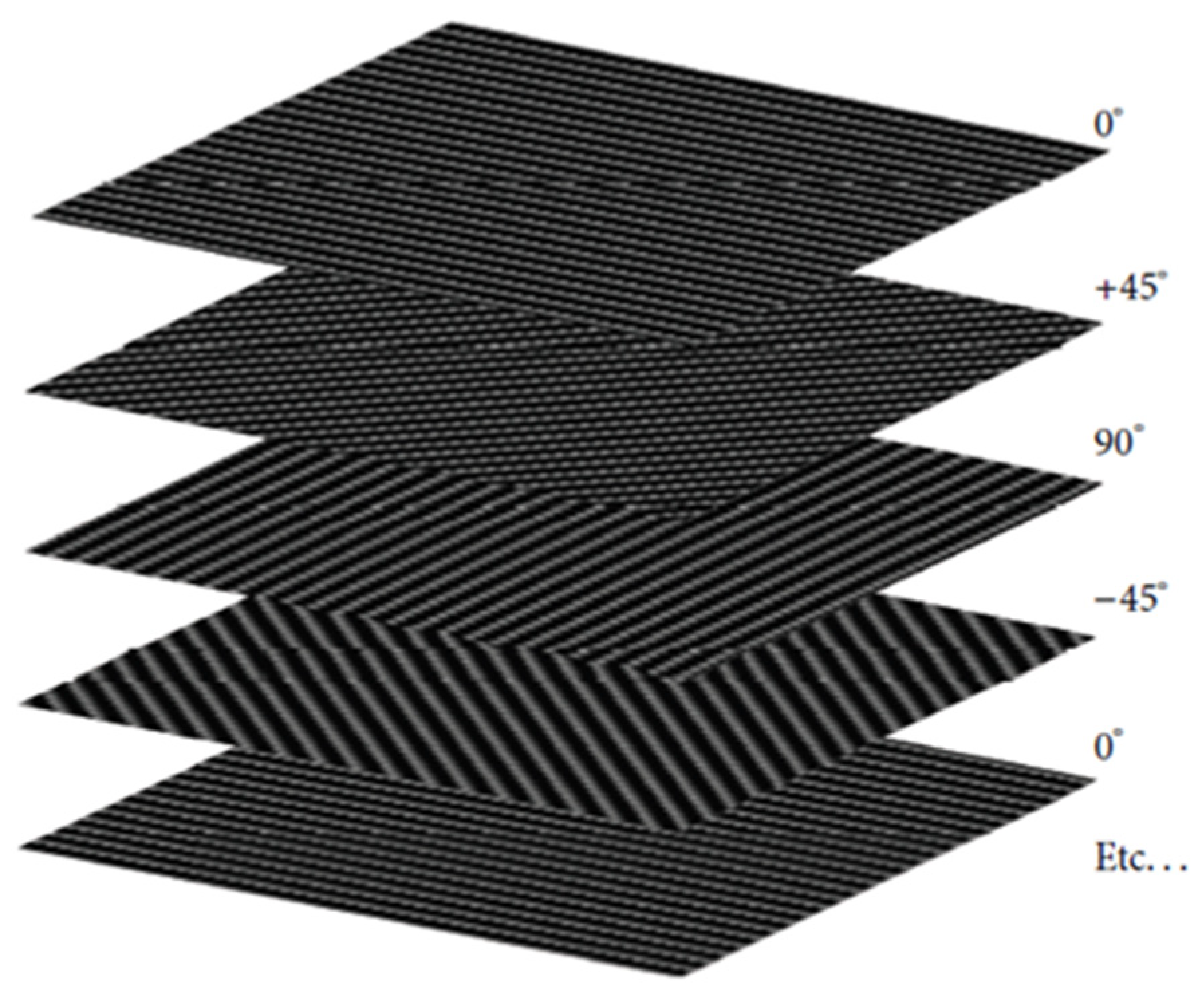
2.1. CFRP Sample
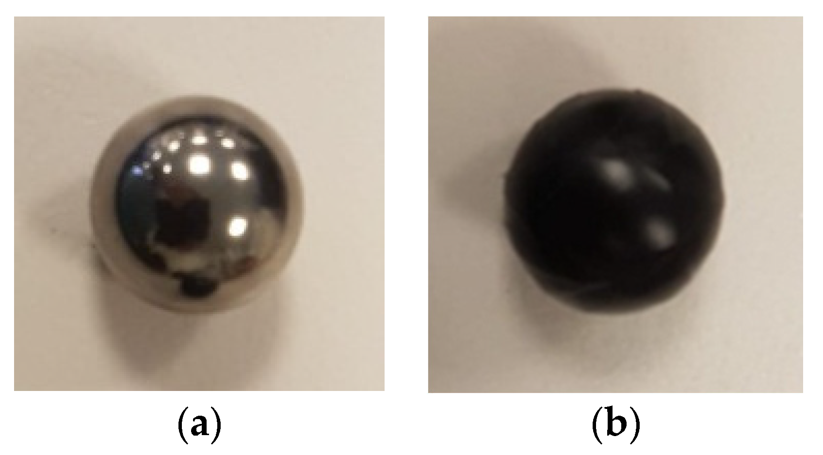
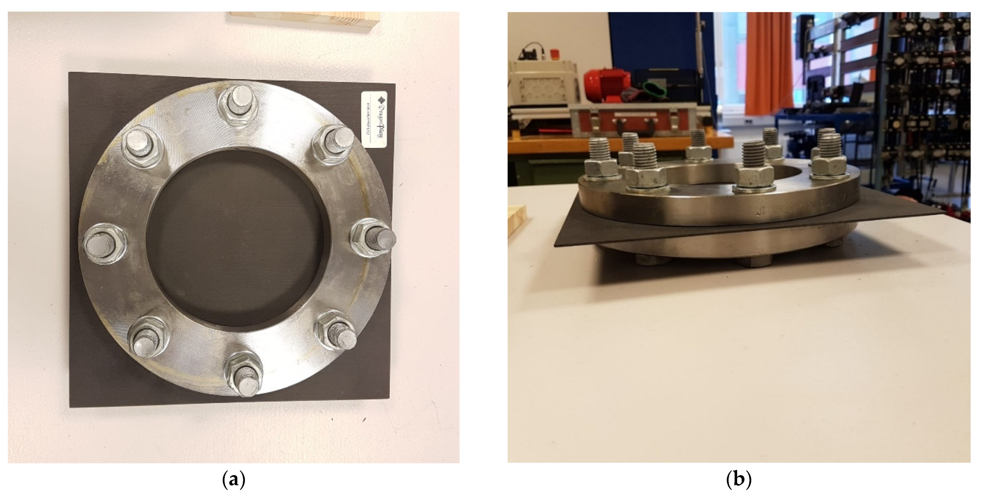
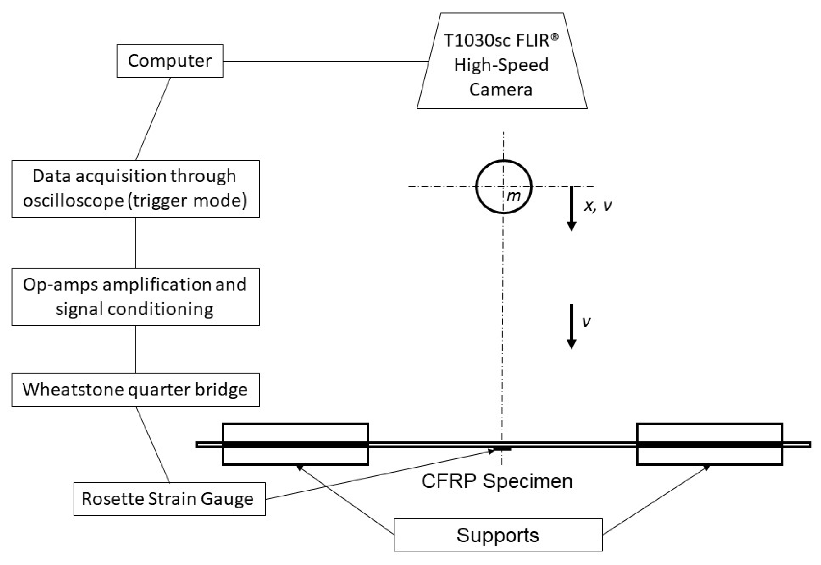
2.2. Experimental Setup to Perform a Drop Test
3. Finite Difference Method (MATLAB®)
3.1. Mathematical Model
3.2. Numerical Analysis
4. Results and Discussion
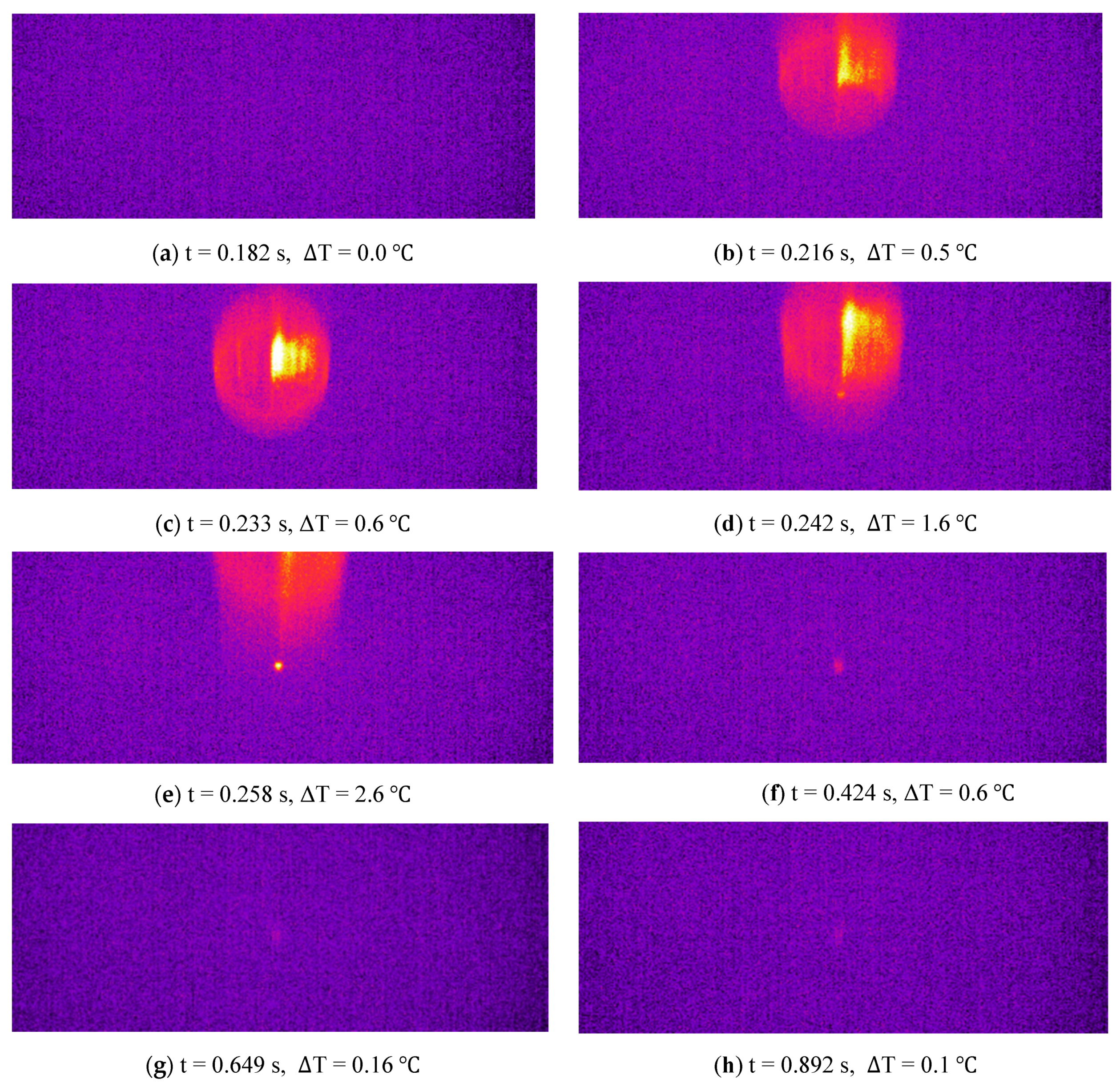
4.1. Thermographic Experimental Results
4.2. Numerical Simulations Results
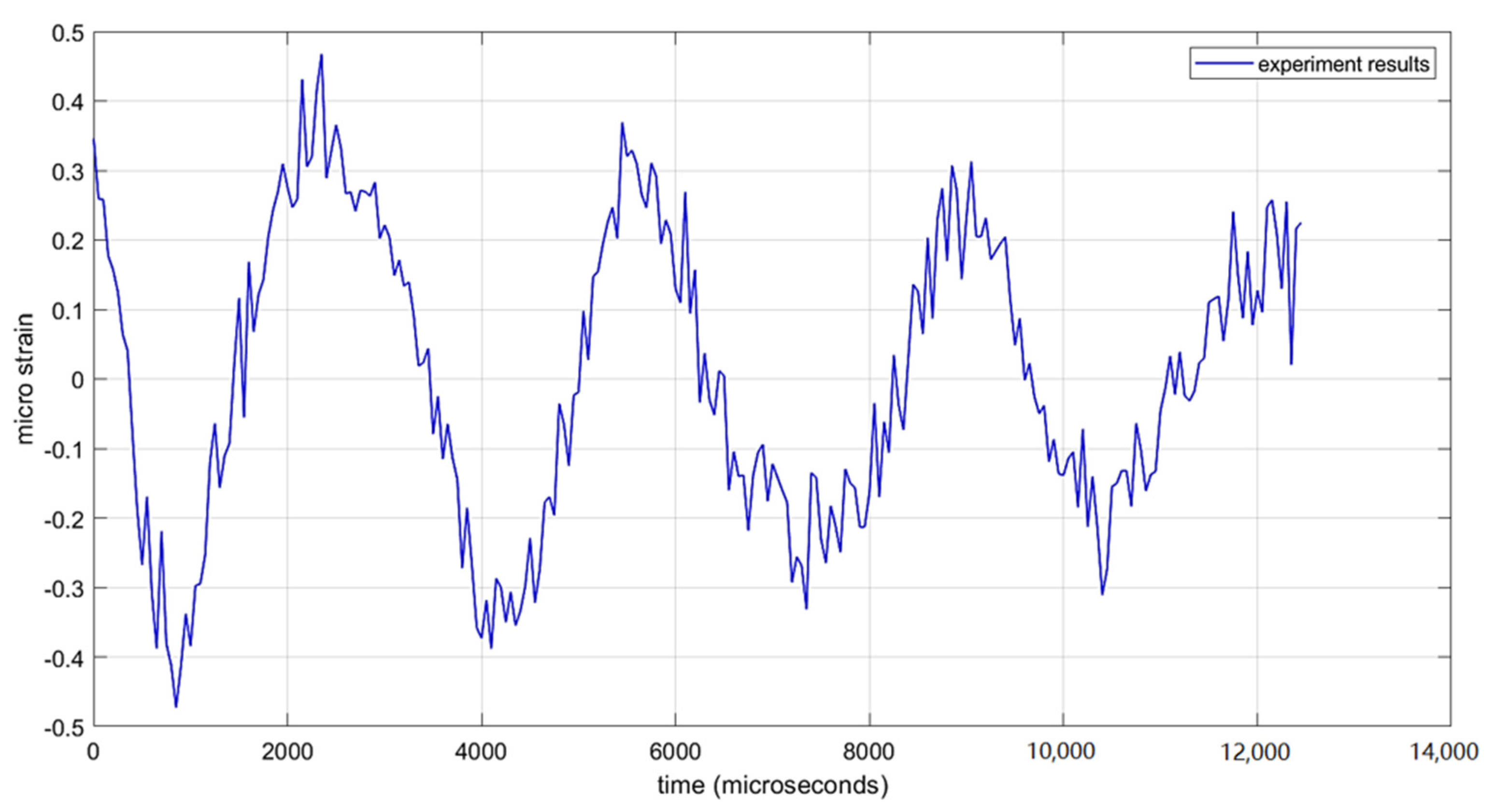
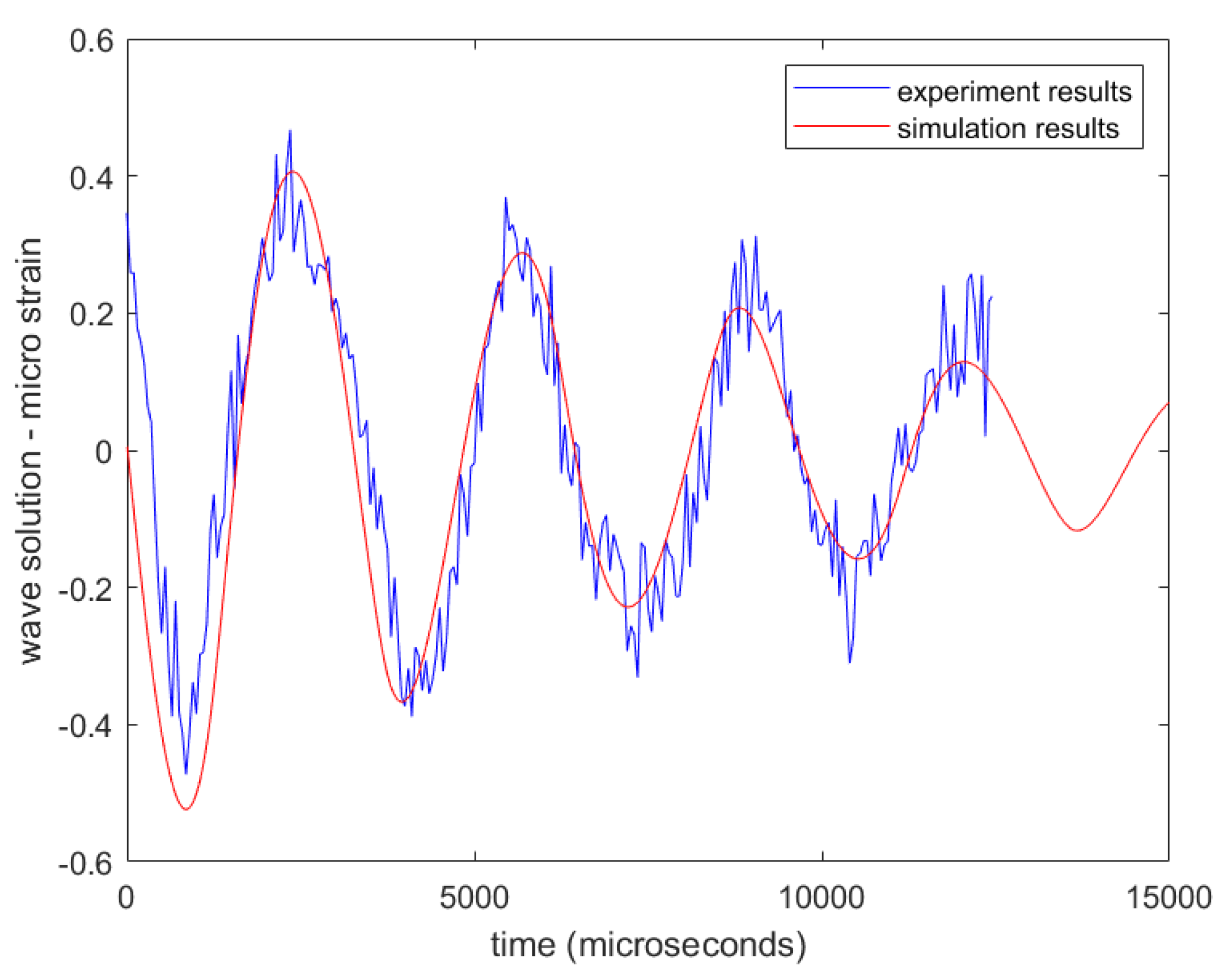
4.2.1. Wave Equation Results
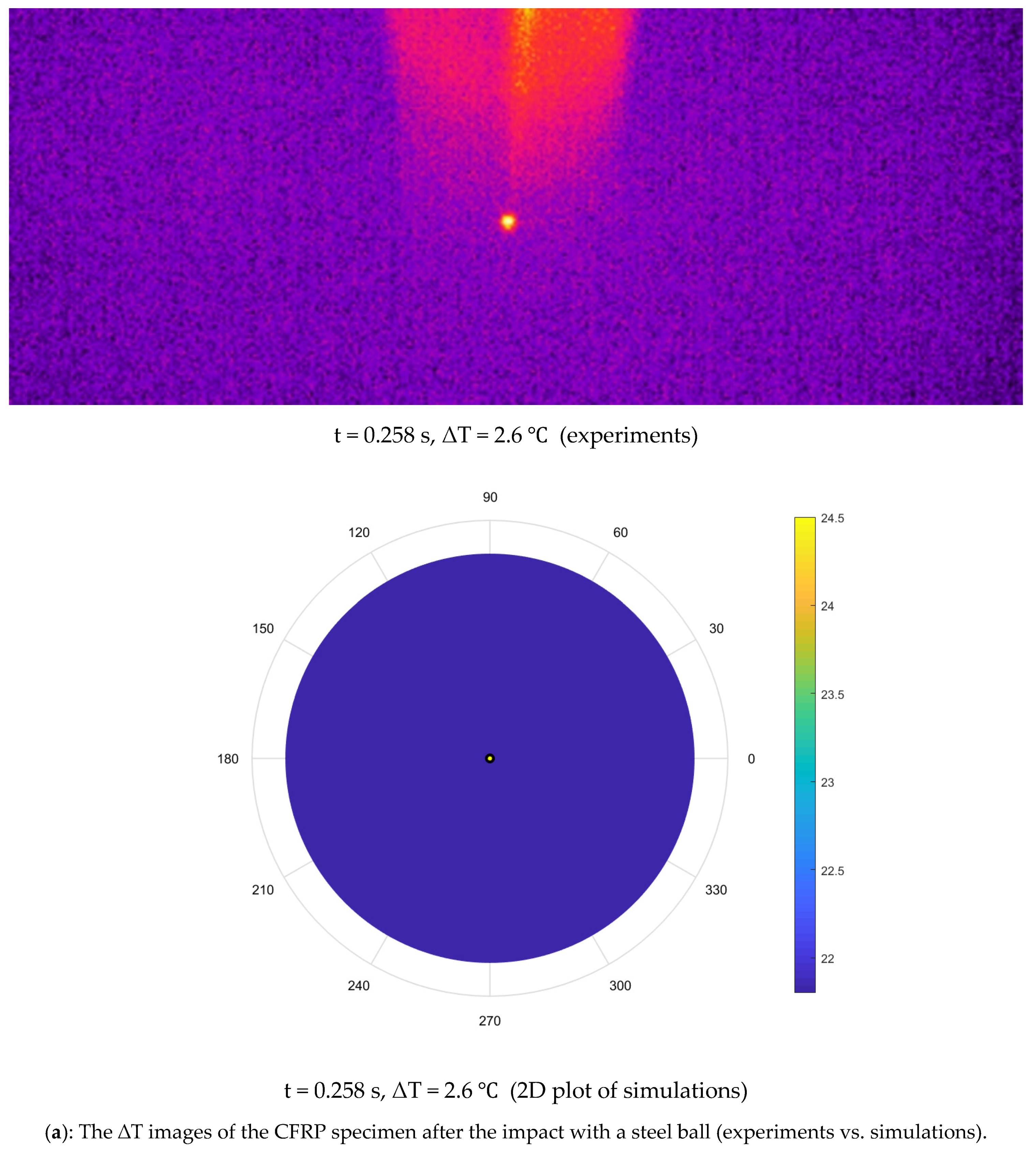
4.2.2. Coupled Heat and Wave Equation Results
4.3. Summary
5. Conclusions
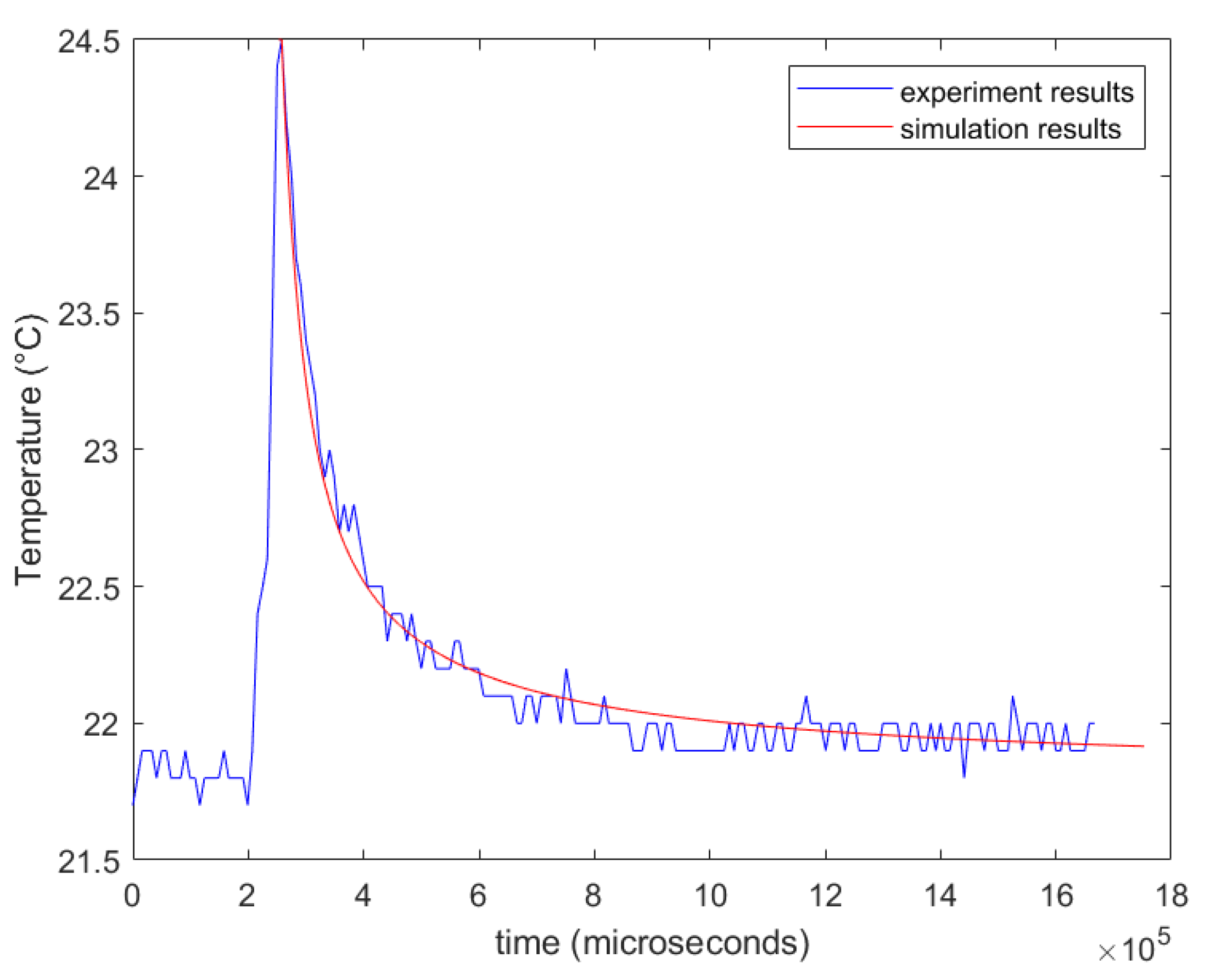
- The thermoelastic phenomenon generated upon impact in a quasi-isotropic CFRP sheet is high-speed and completes in almost 0.015 s.
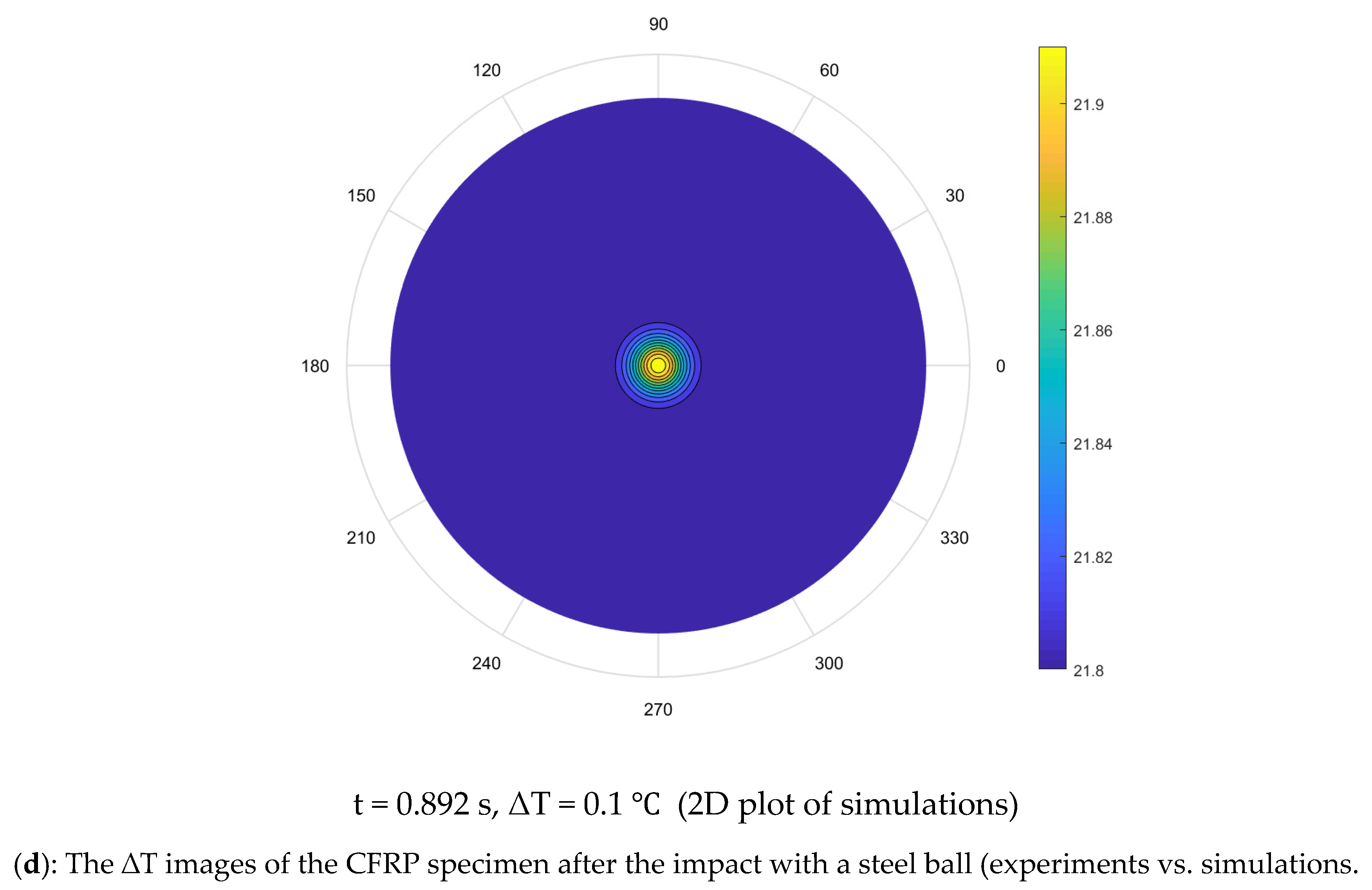
- Heat diffusion from the hotspot, which developed due to friction between the steel ball and the CFRP surface, occurs for nearly 1.2 s.
- No significant effect of the coupling heat and wave equation was observed, as temperature change due to thermoelasticity (elastic waves) was minimal compared to temperature change due to heat conduction.
- We found that thermoelasticity has a negligible effect, and heat diffusion alone is responsible for the heat dissipation in the CFRP.
Supplementary Materials
Author Contributions
Funding
Data Availability Statement
Acknowledgments
Conflicts of Interest
References
- Mouti, Z.; Westwood, K.; Kayvantash, K.; Njuguna, J. Low Velocity Impact Behavior of Glass Filled Fiber-Reinforced Thermoplastic Engine Components. Materials 2010, 3, 2463–2473. [Google Scholar] [CrossRef]
- Troncossi, M.; Taddia, S.; Rivola, A.; Martini, A. Experimental Characterization of a High-Damping Viscoelastic Material Enclosed in Carbon Fiber Reinforced Polymer Components. Appl. Sci. 2020, 10, 6193. [Google Scholar] [CrossRef]
- Boccardi, S.; Boffa, N.D.; Carlomagno, G.M.; Meola, C.; Ricci, F.; Russo, P.; Simeoli, G. Infrared thermography to impact damaging of composite materials. Health Monit. Struct. Biol. Syst. 2017, 10170, 1017004. [Google Scholar] [CrossRef]
- Ciminello, M.; Boffa, N.D.; Concilio, A.; Galasso, B.; Romano, F.P.; Monaco, E. Damage Detection of CFRP Stiffened Panels by Using Cross-Correlated Spatially Shifted Distributed Strain Sensors. Appl. Sci. 2020, 10, 2662. [Google Scholar] [CrossRef] [Green Version]
- Sellitto, A.; Saputo, S.; Di Caprio, F.; Riccio, A.; Russo, A.; Acanfora, V. Numerical–Experimental Correlation of Impact-Induced Damages in CFRP Laminates. Appl. Sci. 2019, 9, 2372. [Google Scholar] [CrossRef] [Green Version]
- Rashid, T.; Khawaja, H.; Edvardsen, K. Determination of Thermal Properties of Fresh Water and Sea Water Ice using Multiphysics Analysis. Int. J. Multiphys. 2016, 10, 277–290. [Google Scholar] [CrossRef]
- Nondestructive Testing of Composites (Polymer- and Metal-Matrix Composites)[1]. Nondestruct. Eval. Mater. 2018, 21, 631–658. [CrossRef]
- Wang, X.; Liu, L.; Shen, W.; Zhou, H. CFRP Reinforced Foam Concrete Subjected to Dynamic Compression at Medium Strain Rate. Materials 2019, 13, 10. [Google Scholar] [CrossRef] [Green Version]
- Cao, H.; Ma, M.; Jiang, M.; Sun, L.; Zhang, L.; Jia, L.; Tian, A.; Liang, J. Experimental Investigation of Impactor Diameter Effect on Low-Velocity Impact Response of CFRP Laminates in a Drop-Weight Impact Event. Materials 2020, 13, 4131. [Google Scholar] [CrossRef]
- Maier, A.; Schmidt, R.; Oswald-Tranta, B.; Schledjewski, R. Non-Destructive Thermography Analysis of Impact Damage on Large-Scale CFRP Automotive Parts. Materials 2014, 7, 413–429. [Google Scholar] [CrossRef]
- Andleeb, Z.; Malik, S.; Hussain, G.; Khawaja, H.; Roemer, J.; Boiger, G.; Moatamedi, M. Multiphysics Study of Infrared Thermography (IRT) Applications. Int. J. Multiphys. 2020, 14, 249–271. [Google Scholar] [CrossRef]
- Warnet, L.L.; Reed, P.E. Falling Weight Impact Testing Principles; Springer: Dordrecht, The Netherlands, 1999; pp. 66–70. [Google Scholar]
- Stanley, P.; Chan, W.K. Quantitative stress analysis by means of the thermoelastic effect. J. Strain Anal. Eng. Des. 1985, 20, 129–137. [Google Scholar] [CrossRef]
- Melvin, A.; Lucia, A.; Solomos, G. The thermal response to deformation to fracture of a carbon/epoxy composite laminate. Compos. Sci. Technol. 1993, 46, 345–351. [Google Scholar] [CrossRef]
- Vaidya, R.U.; Chawla, K. Thermal expansion of metal-matrix composites. Compos. Sci. Technol. 1994, 50, 13–22. [Google Scholar] [CrossRef]
- Nowacki, W. Dynamic problems of diffusion in solids. Eng. Fract. Mech. 1976, 8, 261–266. [Google Scholar] [CrossRef]
- Olesiak, Z.; Pyryev, Y. A coupled quasi-stationary problem of thermodiffusion for an elastic cylinder. Int. J. Eng. Sci. 1995, 33, 773–780. [Google Scholar] [CrossRef]
- Sherief, H.H.; Anwar, M.N. State-space approach to two-dimensional generalized thermoelasticity problems. J. Therm. Stress. 1994, 17, 567–590. [Google Scholar] [CrossRef]
- Sherief, H.H.; Anwar, M.N. Problem in Generalized Thermoelasticity. J. Therm. Stress. 1986, 9, 165–181. [Google Scholar] [CrossRef]
- Sherief, H.H.; Ezzat, M.A. Solution of the generalized problem of thermoelasticity in the form of series of functions. J. Therm. Stress. 1994, 17, 75–95. [Google Scholar] [CrossRef]
- Sherief, H.H. Fundamental solution of the generalized thermoelastic problem for short times. J. Therm. Stress. 1986, 9, 151–164. [Google Scholar] [CrossRef]
- Bayandor, J.; Thomson, R.S.; Scott, M.L.; Nguyen, M.Q.; Elder, D.J. Investigation of impact and damage tolerance in advanced aerospace composite structures. Int. J. Crashworthiness 2003, 8, 297–306. [Google Scholar] [CrossRef]
- Hampson, P.R.; Moatamedi, M. A review of composite structures subjected to dynamic loading. Int. J. Crashworthiness 2007, 12, 411–428. [Google Scholar] [CrossRef]
- Andleeb, Z.; Strand, C.; Malik, S.; Hussain, G.; Khawaja, H.; Boiger, G.; Moatamedi, M. Multiphysics Analysis of CFRP Charpy Tests by varying Temperatures. Int. J. Multiphys. 2020, 14, 143–160. [Google Scholar] [CrossRef]
- Khawaja, H.A.; Moatamedi, M.; Andleeb, Z.; Strand, C.; Chen, P.; Guo, B. Multiphysics Impact Analysis of Carbon Fiber Reinforced Polymer (CFRP) Shell. Explos. Shock Waves High Strain Rate Phenom. 2019, 13, 115–120. [Google Scholar] [CrossRef] [Green Version]
- Solid Carbon Fiber Sheets & Plates (DragonPlate). Available online: https://dragonplate.com/solid-carbon-fiber-sheets-plates (accessed on 5 October 2020).
- Quasi-Isotropic Carbon Fiber Uni Sheet ~2 mm × 6″ × 6″, DragonPlate. Available online: https://dragonplate.com/quasi-isotropic-carbon-fiber-uni-sheet-2mm-x-6-x-6 (accessed on 15 October 2020).
- Khawaja, H.A.; Bertelsen, T.A.; Andreassen, R.; Moatamedi, M. Study of CRFP Shell Structures under Dynamic Loading in Shock Tube Setup. J. Struct. 2014, 2014, 1–6. [Google Scholar] [CrossRef]
- Stange, E.; Andleeb, Z.; Khawaja, H.A. Qualitative visualization of the development of stresses through infrared thermography. Vestnik MGTU 2019, 22, 503–507. [Google Scholar] [CrossRef]
- Stange, E.; Andleeb, Z.; Khawaja, H.A.; Moatamedi, M. Multiphysics Study of Tensile Testing using Infrared thermography. Int. J. Multiphys. 2019, 13, 191–202. [Google Scholar] [CrossRef]
- FLIR T1030sc FLIR Systems. Available online: https://www.flir.asia/support/products/t1030sc/#Overview (accessed on 5 October 2020).
- ResearchIR Measurement, Recording, and Analysis Software FLIR Systems. Available online: https://www.flir.asia/products/researchir/ (accessed on 5 October 2020).
- Zhou, F.; Zhang, J.; Song, S.; Yang, D.; Wang, C. Effect of Temperature on Material Properties of Carbon Fiber Reinforced Polymer (CFRP) Tendons: Experiments and Model Assessment. Materials 2019, 12, 1025. [Google Scholar] [CrossRef] [Green Version]
- Münch, A. Optimal design of the support of the control for the 2-D wave equation: A numerical method. Int. J. Numer. Anal. Model. 2008, 5, 331–351. [Google Scholar]
- Zuazua, E. Boundary observability for the finite-difference space semi-discretizations of the 2-d wave equation in the square. J. Math. Pures Appl. 1999, 78, 523–563. [Google Scholar] [CrossRef] [Green Version]
- Liu, J. Numerical solution of forward and backward problem for 2-D heat conduction equation. J. Comput. Appl. Math. 2002, 145, 459–482. [Google Scholar] [CrossRef]
- Widder, D.V. The Heat Equation; Academic Press Institute: London, UK, 1975. [Google Scholar]
- Dawson, C.N.; Du, Q.; Dupont, T.F. A finite difference domain decomposition algorithm for numerical solution of the heat equation. Math. Comput. 1991, 57, 63. [Google Scholar] [CrossRef]
- Moatamedi, M.; Khawaja, H. Finite Element Analysis; CRC Press (Taylor & Francis): Boca Raton, FL, USA, 2018. [Google Scholar]
- Khawaja, H. Application of a 2-D approximation technique for solving stress analyses problem in FEM. Int. J. Multiphys. 2015, 9, 317–324. [Google Scholar] [CrossRef] [Green Version]
- Khawaja, H.A. Applicability extent of 2-D heat equation for numerical analysis of a multiphysics problem. In AIP Conference Proceedings; AIP Publishing LLC: Melville, NY, USA, 2017; Volume 1798, p. 20075. [Google Scholar] [CrossRef] [Green Version]
- Kashtalyan, M. Principles of Composite Material Mechanics; Taylor & Francis: Abingdon, UK, 2012. [Google Scholar]
- Joven, R.; Das, R.; Ahmed, A.; Roozbehjavan, P.; Minaie, B. Thermal properties of carbon fiber-epoxy composites with different fabric weaves. In Proceedings of the 44th ISTC International SAMPE Technical Conference, Charleston, SC, USA, 22–25 October 2012. [Google Scholar]
- Martins, M.S.S.; Gomes, R.; Pina, L.; Pereira, C.; Reichmann, O.; Teti, D.; Correia, N.; Rocha, N. Highly Conductive Carbon Fiber-Reinforced Polymer Composite Electronic Box: Out-of-Autoclave Manufacturing for Space Applications. Fibers 2018, 6, 92. [Google Scholar] [CrossRef] [Green Version]
- Zhang, X.; Zuazua, E. Control, observation and polynomial decay for a coupled heat-wave system. Comptes Rendus Math. 2003, 336, 823–828. [Google Scholar] [CrossRef]
- Batty, C.; Paunonen, L.; Seifert, D. Optimal energy decay in a one-dimensional coupled wave–heat system. J. Evol. Equ. 2016, 16, 649–664. [Google Scholar] [CrossRef] [Green Version]
- Zhang, X.; Zuazua, E. Long-Time Behavior of a Coupled Heat-Wave System Arising in Fluid-Structure Interaction. Arch. Ration. Mech. Anal. 2007, 184, 49–120. [Google Scholar] [CrossRef]
- Courant, R.; Friedrichs, K.; Lewy, H. Über die partiellen Differenzengleichungen der mathematischen Physik. Math. Ann. 1928, 100, 32–74. [Google Scholar] [CrossRef]


| Carbon Fiber Modulus | 228 GPa |
|---|---|
| Weight of sheet | 72.1 g |
| Density | 1540 kg/m3 |
Publisher’s Note: MDPI stays neutral with regard to jurisdictional claims in published maps and institutional affiliations. |
© 2020 by the authors. Licensee MDPI, Basel, Switzerland. This article is an open access article distributed under the terms and conditions of the Creative Commons Attribution (CC BY) license (http://creativecommons.org/licenses/by/4.0/).
Share and Cite
Andleeb, Z.; Malik, S.; Abbas Khawaja, H.; Samuelsen Nordli, A.; Antonsen, S.; Hussain, G.; Moatamedi, M. Thermoelastic Investigation of Carbon-Fiber-Reinforced Composites Using a Drop-Weight Impact Test. Appl. Sci. 2021, 11, 207. https://doi.org/10.3390/app11010207
Andleeb Z, Malik S, Abbas Khawaja H, Samuelsen Nordli A, Antonsen S, Hussain G, Moatamedi M. Thermoelastic Investigation of Carbon-Fiber-Reinforced Composites Using a Drop-Weight Impact Test. Applied Sciences. 2021; 11(1):207. https://doi.org/10.3390/app11010207
Chicago/Turabian StyleAndleeb, Zahra, Sohail Malik, Hassan Abbas Khawaja, Anders Samuelsen Nordli, Ståle Antonsen, Ghulam Hussain, and Mojtaba Moatamedi. 2021. "Thermoelastic Investigation of Carbon-Fiber-Reinforced Composites Using a Drop-Weight Impact Test" Applied Sciences 11, no. 1: 207. https://doi.org/10.3390/app11010207