
Improvement of a Tunable Stiffness Organ-Grasping Device by Design of a Wavy-Shaped Beam Structure
by
 , ,
, ,
Toshihiro Kawase
1,2,* ,
,
Takaaki Sugino
1,
Shinya Onogi
1,
Kenji Kawashima
3 and
Yoshikazu Nakajima
1,* 1
Department of Biomedical Information, Institute of Biomaterials and Bioengineering, Tokyo Medical and Dental University, Tokyo 113-8510, Japan
2
Institute of Innovative Research, Tokyo Institute of Technology, Kanagawa 226-8503, Japan
3
Department of Information Physics and Computing, The University of Tokyo, Tokyo 113-8656, Japan
*
Authors to whom correspondence should be addressed.
Appl. Sci. 2021, 11(10), 4581; https://doi.org/10.3390/app11104581
Submission received: 14 April 2021
/
Revised: 11 May 2021
/
Accepted: 14 May 2021
/
Published: 17 May 2021
(This article belongs to the Section Mechanical Engineering)
Abstract
:Tunable stiffness mechanisms can increase the noninvasiveness and stability of organ manipulation in laparoscopic liver resection. We have developed an organ-grasping device using beam-shaped tunable stiffness mechanism. Increasing the change ratio of stiffness will improve the performance of the device by offering high flexibility when adhering to the liver surface and high rigidity during the manipulation of the liver; however, optimal design of the beam has not been investigated. In this study, we investigate the wavy structure shape of the device that enhances the change in the ratio of stiffness. To increase the stiffness in a high-stiffness state, we used principal stress lines in the device to design the edge curve of the wavy shape material in the beams. We also investigated the arrangement of the wavy shape to decrease the stiffness in a low-stiffness state. Simulation using finite element method showed that the change ratio of stiffness was improved up to 13.0 by the new wavy shape arranged with the uniformly thick bottom of the waves.
1. Introduction
Noninvasive and stable manipulation of organs is important in laparoscopic liver resection. In the liver resection, surgeons are required to grasp and pull the liver to acquire surgical field and apply tension to the edge of resection line. In current clinical procedures, forceps and retractors are used for this purpose. The devices make contact with the liver on a small area and may apply large stress on the liver. Some researchers have addressed this issue and have developed mechanical devices to assist the liver manipulation with large contact area. To fix the problem, some introduced suction fixation for the devices to hold and manipulate the liver. Some devices were developed with multiple suction pads on a rigid [1,2] or soft body [3,4]. Multiple pads should adhere to the liver surface to enlarge the contact area, and the soft body that could follow the shape of liver without a complicated mechanism was more effective. However, rigidness was also required to hold the liver position by the tool. Thus, balancing shape followability and position-holding ability was a problem to be solved.
A tunable stiffness mechanism is a solution to the problem. This is a category of mechanisms that can change its state from a low-stiffness state, in which the mechanism has high flexibility, to a high-stiffness state, in which it has high rigidity. Although some mechanisms have been implemented by the use of shape memorization material [5,6], heating around the contact surface is not adequate for organ-grasping in terms of safety. Wire-driven mechanisms have also been developed [7,8,9]; however, these require small and complicated mechanisms, and increase the complexity of the grasping device. The jamming mechanism is a tunable stiffness mechanism that exploits friction between granules [10] or layers [11] enclosed by a vacuumed, soft membrane. The mechanism is in a low-stiffness state when the membrane is opened to the atmosphere, and it changes to a high-stiffness state by vacuuming the membrane. We developed an organ-grasping device that uses a tunable stiffness mechanism using two beams for layer jamming, which can follow the shape of liver and obtain rigidity with keeping the shape [12,13] (Figure 1). To increase the ratio of the low-tuned stiffness to the high-tuned stiffness, which we refer as stiffness gain, we incorporated a wavy structure into the beam based on the analysis of stress [13]; however, details of the wavy shape have not been optimized from the viewpoint of mechanics of materials. Larger stiffness gain will realize improved performance of the device, which can contact to the liver surface with larger area in a low-stiffness state and supply the function of position-holding in a high-stiffness state.
In this paper, we investigate the shape of the wavy structure in the tunable stiffness organ grasping device that enhance the stiffness gain. To increase the stiffness in a high-stiffness state, we design the wavy shape based on principal stress lines in the beams. Stiffness maximization of a beam has been approached by optimal truss design and topology optimization. Classical studies on optimal truss design [14,15] showed that the elements aligned to the principal stress lines maximize the stiffness of structural objects. Principal stress line-based design was recently applied to the area of additive manufacturing to design an optimal beam shape [16] or determine filament alignment [17]. Topology optimization methods can optimize the shape of materials numerically and have been used in the area of architecture to make stiffer beams [18] and design building frames [19]. In both approaches, the designs in previous studies have complex structure with many holes, which are difficult to manufacture in a small body that can be used in laparoscopic surgery. This study uses the principal stress lines in beams as the edge shape of the wavy-shaped structure with the similar topology as our previous device to suppress the shear stress that deforms the wavy shape. Unlike the previous studies to increase the stiffness of the beams, the design for a tunable stiffness mechanism should keep a low stiffness condition. Thus, we also investigated a design to reduce the stiffness in a low-stiffness state.
2. Methods
2.1. Mechanism of the Device
Figure 2 shows the structure and basic of organ-grasping device. The device consists of the two soft beams covered by thin membrane. A suction tube and a handle are attached to the top of the device. The bottom of the device is opened to the air, and beams have holes for the airway. The tube is connected to a medical vacuum pump. When the bottom of the device is in the air, air is vacuumed from the bottom, and the two beams make a gap (Figure 2a). In this state, the beams behave as two thin beams and retain flexibility. After adhering to the liver, the device bottom opening is covered by the liver surface, and the two beams are constrained by suction (Figure 2b). In this state, the two beams act as a single thicker beam and become stiffer than the separated beams.
The stiffness of the device in the two states has been analyzed following beam theory [13]. Beams with homogeneous materials were supposed. In a low-stiffness state, the bending stiffness of the two beams is:
where is elastic modulus, are the second moment of area for a single beam, is the width of beam, and is the height of single beam. In a high-stiffness state, the bending stiffness is the stiffness of a beam with double thickness as follows:
From the ratio between and , the stiffness gain is four, theoretically.
To obtain more stiffness gain, non-homogeneous beam was designed. Figure 3a shows horizontal normal and shear stress in the device working in a high-stiffness state. While the device is pulled by forceps, adhesion force under the device applies bending moment to the device. This causes horizontal normal force and shear force in the device. As shown in Figure 3a, the normal force is maximized on the surface of the device, and the shear force is maximized on the center line of the device. We have designed the beam to resist the stress [13]. Figure 3b shows the designed beam and stress while the device is grasped and pulled. The beam is composed of a wavy-shaped high-stiffness material (rubber) with flat surface on the outer surface of the beams, and the gaps are filled with low-stiffness material (silicone). The high-stiffness material around the surface resist to the normal stress in a high-stiffness state, and the wavy shape retains flexibility in a low-stiffness state. On the inner surface of the beams, friction sheets (silicone) were attached to prevent slipping between the two beams caused by shear stress in a high-stiffness state. Our experiments showed that the device with the structure in a high-stiffness state were 5.48 times harder than the device in low-stiffness state, which was harder than the expected stiffness from the beam theory [13].
2.2. Improved Design of the Beams
In this study, we approached the task to increase the stiffness gain of the device by increasing the stiffness in a high-stiffness state with suppressing the stiffness in a low-stiffness state. As written above, the wavy structure was also adapted in line with this strategy; however, optimal shape of the wave has not been investigated. We improve the beam design by two-step process; first investigate the shape of the wave to increase the stiffness in a high-stiffness state, second explore the arrangement of waves to decrease the stiffness in a low-stiffness state.
The principal stress line is a concept that we use to maximize the stiffness of structures. Here we introduce the concept of principal stress line in two-dimensional material. Generally, a small square area around a point in the material receives normal and shear stress (Figure 4a). By rotating the square, we can find the orientation in which only normal stress is applied on the edges (Figure 4b). The normal stress in this orientation is called principal stress. The direction of the principal stress is the solutions of the following equation:
where and are normal stress in the direction of axis and axis, respectively, and is shear stress. Four orientations that satisfies the equation correspond to the four normal stress on the edges. The angles gradually change according to the position and lead two sets of streamlines that are orthogonal each other. The lines are called principal stress lines (Figure 4b).
The principal stress lines are relative to the deformation of curve in the material. The relationship is shown in Figure 4c,d. A curve that deviates from the principal stress lines receives normal and shear stress (Figure 4c). Let the angle between the curve and principal stress line be small. From Mohr’s stress circle, the normal stress and and the shear stress are as follows:
where and are the principal stress. On the other hand, a curve along a principal stress line receives only the normal stress and (Figure 4d). These suggest that the curve on the principal stress line gives the minimal deformation because of the elimination of shear stress.
Our strategy to form the shape of the wave is to make the edge of the wave follow the principal stress lines in a high-stiffness state. This strategy will suppress the shear stress across the edge of material and is expected to suppress the deformation.
To design the wavy shape, we first derive the principal stress line of the device in a high-stiffness state. A part of the device in a high-stiffness state can be modeled as a cantilever, which is fixed on the position of handle and uniform load is applied on as Figure 5a,b. For simplicity, we supposed that the cantilever is made of homogeneous material in the following calculation. From the beam theory, normal and shear stress in the cantilever is as follows:
where and are horizontal and vertical normal stress, respectively, is shear stress, is the uniform load, and are the length and width of beam, respectively, and is the half of height of the cantilever. By substituting the stress into Equation (3), we can derive the equation of the direction of principal stress lines as follows:
Figure 5c shows the lines in the cantilever in Figure 5b. Solid lines show the lines along which only compressive stress is applied, and dashed lines show the lines along which only tensile stress is applied.
We designed two patterns of beams for the device. The first one is the design with waves of uniform pitch (Figure 5d), as shown in our previous devices [13]. The wavy shapes are truncated at the top to put friction sheets. Since the slope of principal stress lines in this condition is shallower around the fixed edge, the high-stiffness material is thicker around the handle. This may increase the stiffness of a single beam and decrease the stiffness gain. The second one has intervals changing monotonically and the wave bottom thickened uniformly (Figure 5e). This design will decrease the stiffness of single beam and increase the stiffness gain. In both designs, the fixed edges (the left edges in Figure 5d,e) are filled by pillars with the shape of principal stress lines to keep the distance between the high-stiffness material and the friction sheet.
3. FEM Study
3.1. Simulation Settings
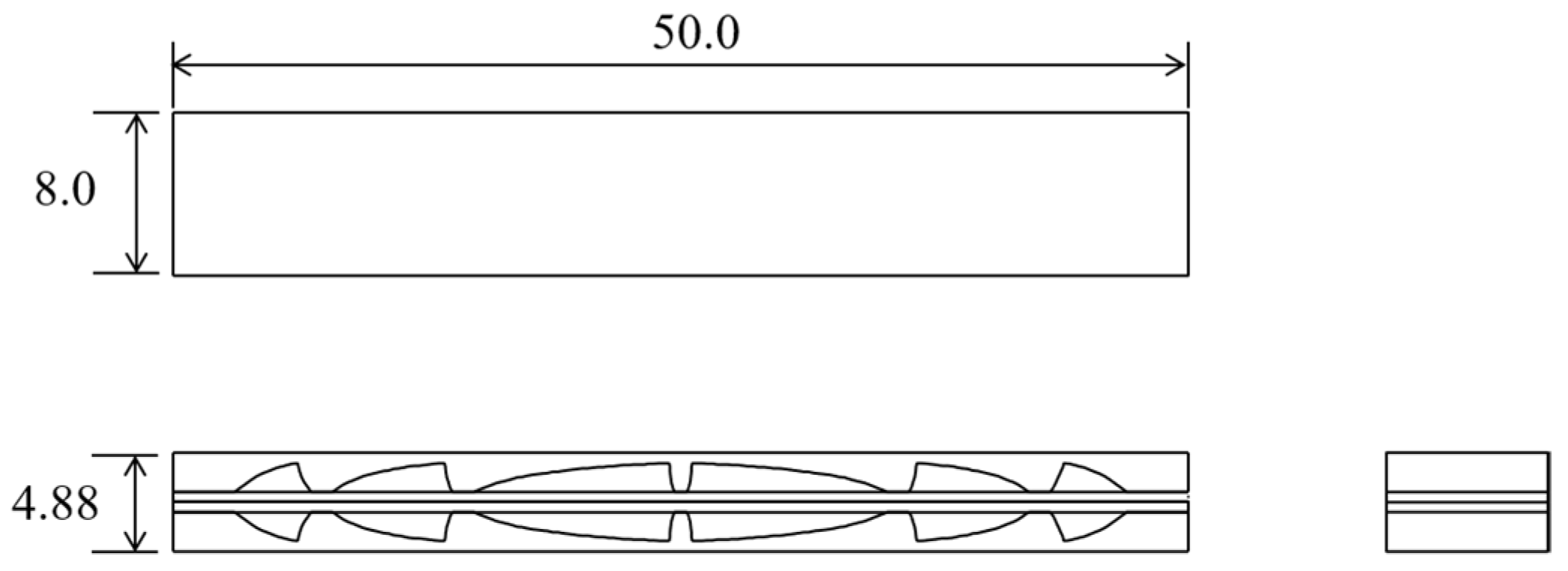
We compared the stiffness gain of proposed designs with the gain of other designs by simulation using finite element method (FEM). Figure 6 shows the four models we compared, which were a homogeneous beam (Homogeneous), the principal-stress-line (PSL)-based design with uniform pitch (PSL-pitch), the PSL-based design with uniform bottom thickness (PSL-thickness), and a beam using uniform pitch pillars (Pillars). These models were composed of the two beams made with high-stiffness material (Young’s modulus 20 MPa, Poisson’s ratio 0.45, maximum thickness 1.94 mm) and friction sheets (Young’s modulus 3.0 MPa, Poisson’s ratio 0.49, thickness 0.5 mm). Spaces between high-stiffness material and friction sheets were kept void. The length, height and width of the device were 50.0 mm, 4.88 mm and 8.0 mm, respectively. The edge curves of the two PSL-based models consisted of two sets of streamlines that were symmetrically aligned about the boundary surfaces of the two beams. The thickness of troughs in PSL-thickness was 0.81 mm, which was the same as the previously implemented device [13]. Lines for the edge of PSL-pitch intersected the boundary surfaces of the two beams at points 5.0 mm apart, whose distance from the fixed edge were 0.0, 5.0, …, 50.0 mm. These two models were designed based on the curves drawn by MATLAB (The MathWorks Inc., Natick, MA, USA) and imported to Fusion 360 (Autodesk Inc., San Rafael, CA, USA). The pitch of the pillars in Pillars design was set to 5.0 mm to match with the PSL-pitch design. The roots of the pillars were filleted by exponential curves.
In the simulation, a vertical point load was applied on the right edge of the device fixed by the left edge. The load was 0.1 N in a high-stiffness state and 0.01 N in a low-stiffness state. Fusion 360 was used for FEM computation. Mesh elements were quadratic tetrahedra with the mean size 0.5 mm. The contact surfaces of the two beams were bonded in a high-stiffness state and set as sliding surfaces in a low-stiffness state. The bending stiffness in the two states was given as:
where was the point load and was the maximum vertical deflection. The stiffness gain was calculated from the higher stiffness and the lower stiffness as
3.2. Results
Figure 7 shows the bending stiffness (Figure 7a) and stiffness gain (Figure 7b) given in the four conditions, beams with Homogeneous, PSL-pitch, PSL-thickness, and Pillars designs. Maximum stiffness gain 13.0 was observed in PSL-thickness as shown in Figure 7b. This was greater than Pillars, which gave the stiffness gain 11.0. As shown in Figure 7a, the increased gain was caused by the higher stiffness of PSL-thickness than Pillars in a high-stiffness state. The gain in PSL-pitch was 9.5, which was smaller than Pillars (Figure 7b). This condition showed higher stiffness than Pillars in a high-stiffness state; however, its stiffness gain was smaller because the stiffness in a low-stiffness state was also higher (Figure 7a). Homogeneous materials showed the stiffness gain 4.5 (Figure 7b), which was slightly larger than four of the theoretical predictions because of the second moment of area of the high-stiffness material in a high-stiffness state was increased by the height of friction sheets.
Figure 8 shows the maximum and minimum principal stress in a high-stiffness state of the four conditions. Positive values in the maximum principal stress are tensile stress, and negative values in the minimum principal stress are compressive stress. PSL-pitch showed similar distribution as the homogeneous material (Figure 8a,b). In the case of Pillars (Figure 8d), stress was concentrated on the surface of the device (Figure 8f). On the other hand, the PSL-thickness distributed the stress in the high-stiffness material (Figure 8c,e).
Figure 9 shows the maximum and minimum principal stress in a low-stiffness state of the four conditions. In the cases of PSL-pitch and the homogeneous material, stress was concentrated on the top or bottom edge of the high-stiffness material. In the cases of PSL-thickness and Pillars, the stress was concentrated on the friction sheets or the other side of the high-stiffness material.
4. Discussion
The simulation showed that the PSL-thickness design gives higher stiffness gain than Pillars or PSL-pitch designs. The increased gain was caused by relatively high stiffness in a high-stiffness state and low stiffness in a low-stiffness state. Distributed stress in Figure 8c suggests that the edge of the PSL-based design aligned with stress streamline in the material in a high-stiffness state. This would suppress not only the deformation of the wavy shapes, but also the concentrated stress around the surface, both of which degrade the stiffness. In a low-stiffness state, the stress distribution in the PSL-thickness was similar to Pillars. The transition of stress to friction sheets, which was not found in the other two designs, would contribute to decrease the stiffness in a low-stiffness state. In the PSL-pitch, the distribution was similar to the homogeneous material in both states. This would be caused by the small depth of notch around the fixed edge, where the stress is larger than the other side of beam. This is the consequence of the shape of principle stress lines, which have gentler slope around the fixed edge (Figure 5c). Thus, the principal stress lines should be used with an adequate pitch in the design of the wavy shape.
The new design of the beams will improve functionality of the beam-shaped organ-grasping device by incorporated into the beams. PSL-thickness design has higher stiffness gain than the other compared designs and could be used to increase flexibility in a low-stiffness state and/or rigidity in a high-stiffness state. The higher flexibility and rigidity improve the shape-followability and position-holding ability against the organ, respectively. The design based on the cantilever model can be used for the real device as shown in Figure 10. The center of the device is supposed as the place of handle. The performance of proposed structure should be evaluated in physical experiments, which should be investigated in our future work.
5. Conclusions
To improve the functionality of tunable stiffness organ-grasping device, we developed designs of the beams used in the device to improve the stiffness gain. Principal stress lines were used as the edge curve of the wavy shape material in the beams. The FEM study showed that the stiffness gain was improved to 13.0 by arranging the wavy shape with a uniformly thick bottom of waves. The design of the beams will enhance the ability of beam-shaped tunable stiffness mechanism and improve shape followability and position-holding ability of the organ-grasping device, which can help noninvasive and stable manipulation. Our future work is to evaluate the performance of the proposed design in physically implemented devices.
Author Contributions
Conceptualization, T.K. and Y.N.; methodology, T.K.; software, T.K.; investigation, T.K.; writing—original draft preparation, T.K.; writing—review and editing, T.S., S.O., K.K. and Y.N.; visualization, T.K.; supervision, K.K. and Y.N.; project administration, K.K. and Y.N.; funding acquisition, T.K., K.K. and Y.N. All authors have read and agreed to the published version of the manuscript.
Funding
This work was supported by RIVERFIELD, Inc. This research is also based on the Cooperative Research Project of the Research Center for Biomedical Engineering.
Institutional Review Board Statement
Not applicable.
Informed Consent Statement
Not applicable.
Data Availability Statement
All the data we showed were collected in numerical simulation. They do not need to be declared here.
Conflicts of Interest
The authors declare no conflict of interest.
References
- Osaki, M.; Omata, T.; Takayama, T.; Ohizumi, H. Transformable lung positioner for thoracoscopic surgery. In Proceedings of the 2011 IEEE/SICE International Symposium on System Integration (SII), Kyoto, Japan, 20–22 December 2011; pp. 138–143. [Google Scholar] [CrossRef]
- Gan, P. A novel liver retractor for reduced or single-port laparoscopic surgery. Surg. Endsc. 2014, 28, 331–335. [Google Scholar] [CrossRef]
- Kuwahara, K.; Tsukagoshi, H.; Kitagawa, A. A soft finger with the function of attaching and holding internal organs referring to an octopus sucker. In Proceedings of the JSME Conference Robotics and Mechatronics, Tsukuba, Japan, 22–25 May 2013. 1A1-B14. [Google Scholar] [CrossRef]
- Takayama, T.; Kuroda, K.; Omata, T. Suction hand for grasping large internal organs for laparoscopic surgery. In Proceedings of the JSME Conf. Robotics and Mechatronics, Toyama, Japan, 25–29 May 2014. 3P1-C02. [Google Scholar] [CrossRef]
- Cheng, N.; Ishigami, G.; Hawthorne, S.; Chen, H.; Hansen, M.; Telleria, M.; Playter, R.; Iagnemma, K. Design and analysis of a soft mobile robot composed of multiple thermally activated joints driven by a single actuator. In Proceedings of the 2010 IEEE International Conference Robot and Automation, Anchorage, AK, USA, 3–7 May 2010; pp. 5207–5212. [Google Scholar] [CrossRef]
- Zhang, Y.-F.; Zhang, N.; Hingorani, H.; Ding, N.; Wang, D.; Yuan, C.; Zhang, B.; Gu, G.; Ge, Q. Fast-Response, stiffness-tunable soft actuator by hybrid multimaterial 3D printing. Adv. Funct. Mater. 2019, 29, 1806698. [Google Scholar] [CrossRef]
- Yamanaka, N.; Matsumiya, K.; Masamune, K.; Dohi, T.; Yamashita, H.; Chiba, T.; Liao, H. Balloon-based manipulator with multiple linkages for intrauterine surgery. In Proceedings of the 2007 IEEE/RSJ International Conference Intelligent Robots System, San Diego, CA, USA, 29 October–2 November 2007; pp. 1278–1283. [Google Scholar] [CrossRef]
- Degani, A.; Choset, H.; Zubiate, B.; Ota, T.; Zenati, M. Highly articulated robotic probe for minimally invasive surgery. In Proceedings of the 2006 IEEE International Conference Robotics and Automation, Orlando, FL, USA, 15–19 May 2006; pp. 4167–4172. [Google Scholar] [CrossRef] [Green Version]
- Kim, Y.-J.; Cheng, S.; Kim, S.; Iagnemma, K. A stiffness-adjustable hyperredundant manipulator using a variable neutral-line mechanism for minimally invasive surgery. IEEE Trans. Robot. 2014, 30, 382–395. [Google Scholar] [CrossRef] [Green Version]
- Brown, E.; Rodenberg, N.; Amend, J.; Mozeika, A.; Steltz, E.; Zakin, M.R.; Lipson, H.; Jaeger, H.M. Universal robotic gripper based on the jamming of granular material. Proc. Natl. Acad. Sci. USA 2010, 107, 18809–18814. [Google Scholar] [CrossRef] [Green Version]
- Kim, Y.-J.; Cheng, S.; Kim, S.; Iagnemma, K. A novel layer jamming mechanism with tunable stiffness capability for minimally invasive surgery. IEEE Trans. Robot. 2013, 29, 1031–1042. [Google Scholar] [CrossRef]
- Kim, J.; Nakajima, Y.; Kobayashi, K. A suction-fixing, stiffness-tunable liver manipulator for laparoscopic surgeries. IEEE/ASME Trans. Mechatron. 2018, 23, 262–273. [Google Scholar] [CrossRef]
- Nakajima, Y.; Suzuki, R.; Suzuki, Y.; Sugino, T.; Kawase, T.; Onogi, S.; Seki, H.; Fujiwara, T.; Ouchi, K. Suction-fixing surgical device for assisting liver manipulation with laparoscopic forceps. Int. J. CARS 2020, 15, 1653–1664. [Google Scholar] [CrossRef] [PubMed]
- Michell, A.G.M. The limits of economy of material in frame-structures. Pholos. Mag. 1904, 6, 589–597. [Google Scholar] [CrossRef] [Green Version]
- Hegemier, G.A.; Prager, W. On Michell trusses. Int. J. Mech. Sci. 1969, 11, 209–215. [Google Scholar] [CrossRef]
- Li, Y.; Chen, Y. Beam structure optimization for additive manufacturing based on principal stress lines. In Proceedings of the Solid Freeform Fabrication Proceedings, Austion, TX, USA, 9–11 August 2010; pp. 666–678. [Google Scholar]
- Tam, K.-M.M.; Mueller, C.T. Additive manufacturing along principal stress lines. 3D Print. Addit. Manuf. 2017, 4, 63–81. [Google Scholar] [CrossRef]
- Tsavdaridis, K.D.; Kingman, J.J.; Toropov, V.V. Application of structural topology optimisation to perforated steel beams. Comput. Struct. 2015, 158, 108–123. [Google Scholar] [CrossRef] [Green Version]
- Stromberg, L.L.; Beghini, A.; Baker, W.F.; Paulino, G.H. Application of layout and topology optimization using pattern gradation for the conceptual design of buildings. Struct. Multidisc. Optim. 2011, 43, 165–180. [Google Scholar] [CrossRef] [Green Version]
Figure 1.
Tunable stiffness organ-grasping device in a previous work [13]. (a) Concept. (b) Prototype. (c) Experimental scene with porcine liver.
Figure 1.
Tunable stiffness organ-grasping device in a previous work [13]. (a) Concept. (b) Prototype. (c) Experimental scene with porcine liver.
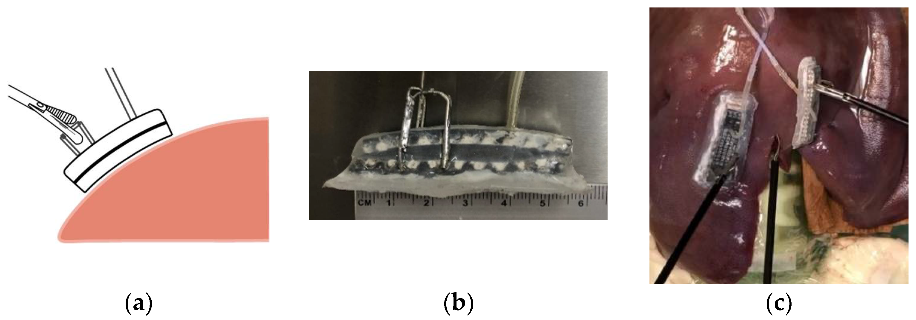
Figure 2.
Structure and basic of the organ-grasping device. (a) The device in a low-stiffness state. (b) The device in a high-stiffness state.
Figure 2.
Structure and basic of the organ-grasping device. (a) The device in a low-stiffness state. (b) The device in a high-stiffness state.

Figure 3.
Stress in the device. (a) Normal and horizontal shear stress in the grasped device in a high-stiffness state. (b) The wavy-shaped beam and stress while the device is grasped and pulled.
Figure 3.
Stress in the device. (a) Normal and horizontal shear stress in the grasped device in a high-stiffness state. (b) The wavy-shaped beam and stress while the device is grasped and pulled.

Figure 4.
Illustration of principal stress lines. (a) Stress on a small square in the material. (b) Principal stress and principal stress lines. (c) Stress on a line deviated from principal stress lines. (d) Stress on a line aligned to principal stress lines. Black and white arrows represent normal and shear stress, respectively.
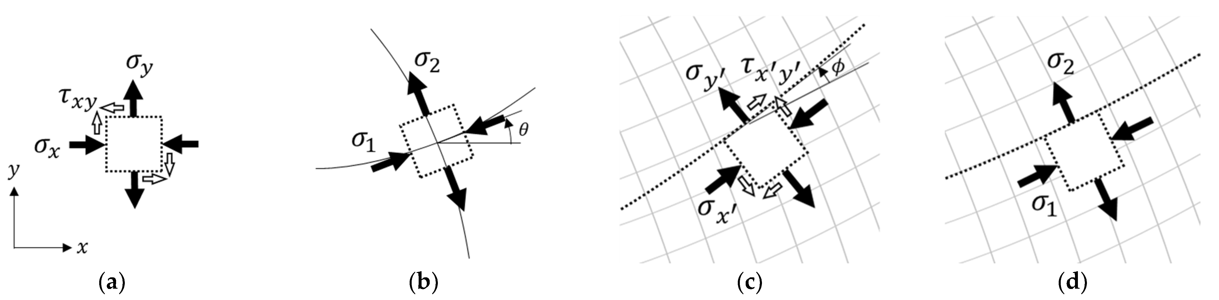
Figure 5.
Beam design using principal stress lines. A part of the device is modeled as a cantilever (a) Based on the cantilever model (b), principal stress lines are derived (c). Solid and dashed lines correspond to compressive and tensile stress, respectively. We design the structures of the device using principal stress lines with uniform pitch (d) and uniform bottom thickness (e).

Figure 6.
Models compared in FEM study. (a) Homogeneous material (Homogeneous). (b) Principal-stress-line (PSL)-based design with uniform pitch (PSL-pitch). (c) PSL-based design with uniform bottom thickness (PSL-thickness). (d) Beam using uniform pitch pillars (Pillars).
Figure 6.
Models compared in FEM study. (a) Homogeneous material (Homogeneous). (b) Principal-stress-line (PSL)-based design with uniform pitch (PSL-pitch). (c) PSL-based design with uniform bottom thickness (PSL-thickness). (d) Beam using uniform pitch pillars (Pillars).
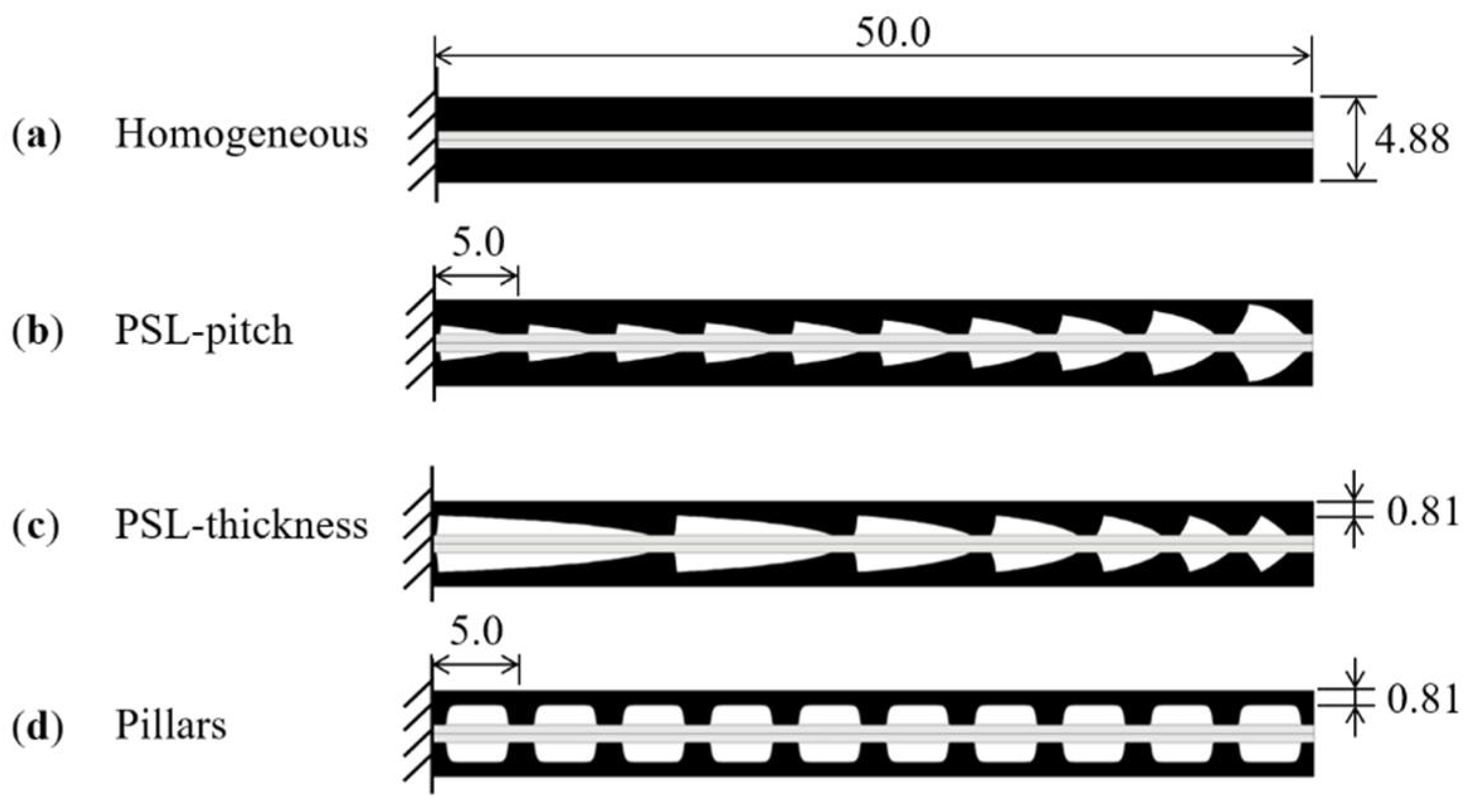
Figure 7.
Stiffness of the device in high-stiffness and low-stiffness states (a); the stiffness gain (b) calculated by simulation for the four conditions. Homogeneous, PSL-pitch, PSL-thickness and Pillars.
Figure 7.
Stiffness of the device in high-stiffness and low-stiffness states (a); the stiffness gain (b) calculated by simulation for the four conditions. Homogeneous, PSL-pitch, PSL-thickness and Pillars.
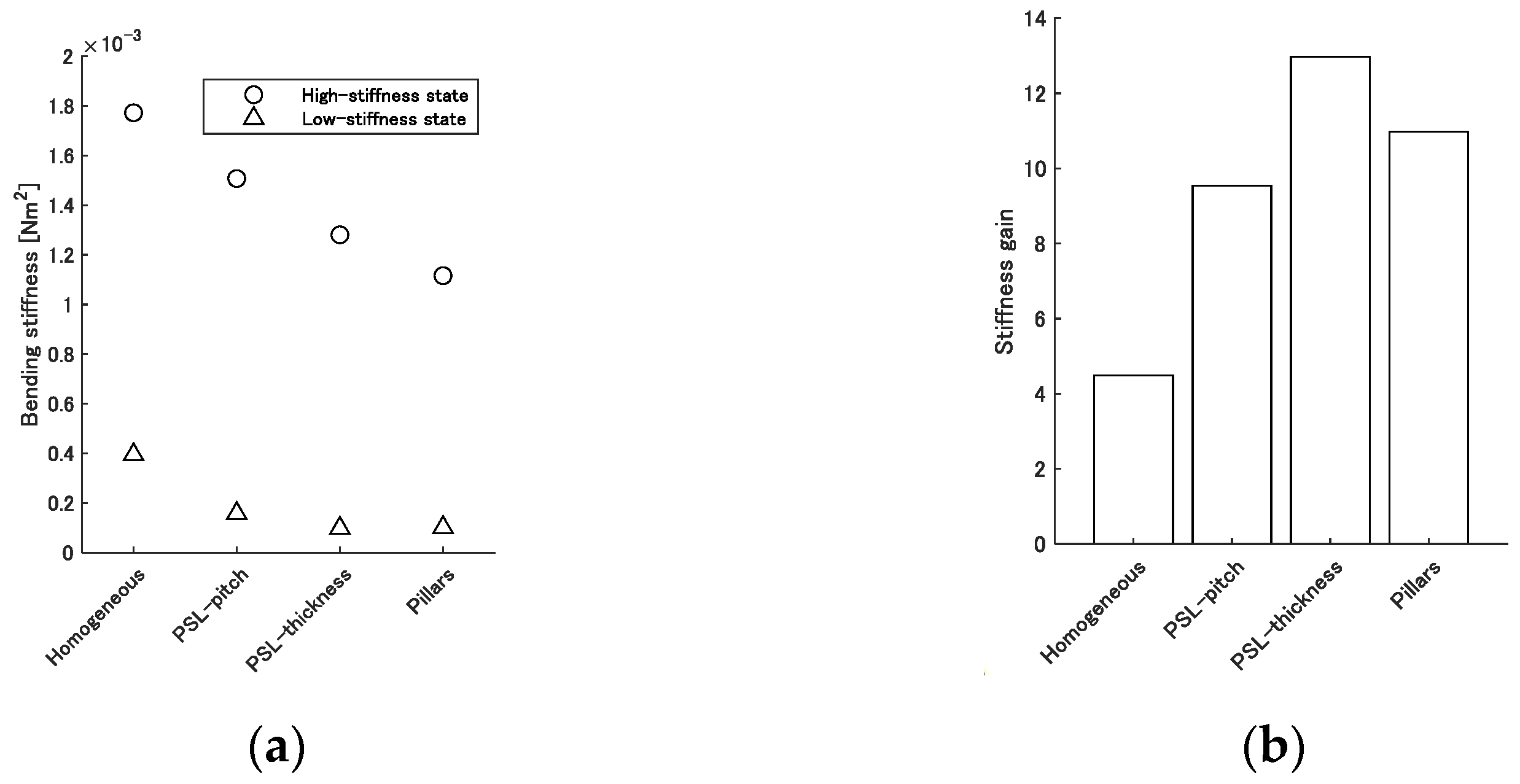
Figure 8.
Maximum and minimum principal stress in a high-stiffness state in the four conditions. Homogeneous (a), PSL-pitch (b), PSL-thickness (c) and Pillars (d). Magnified images of (c,d) with finer stress scales are shown in (e,f), respectively. The load size was 0.1 N. The size of maximum vertical deflection in each condition is shown in (a–d).
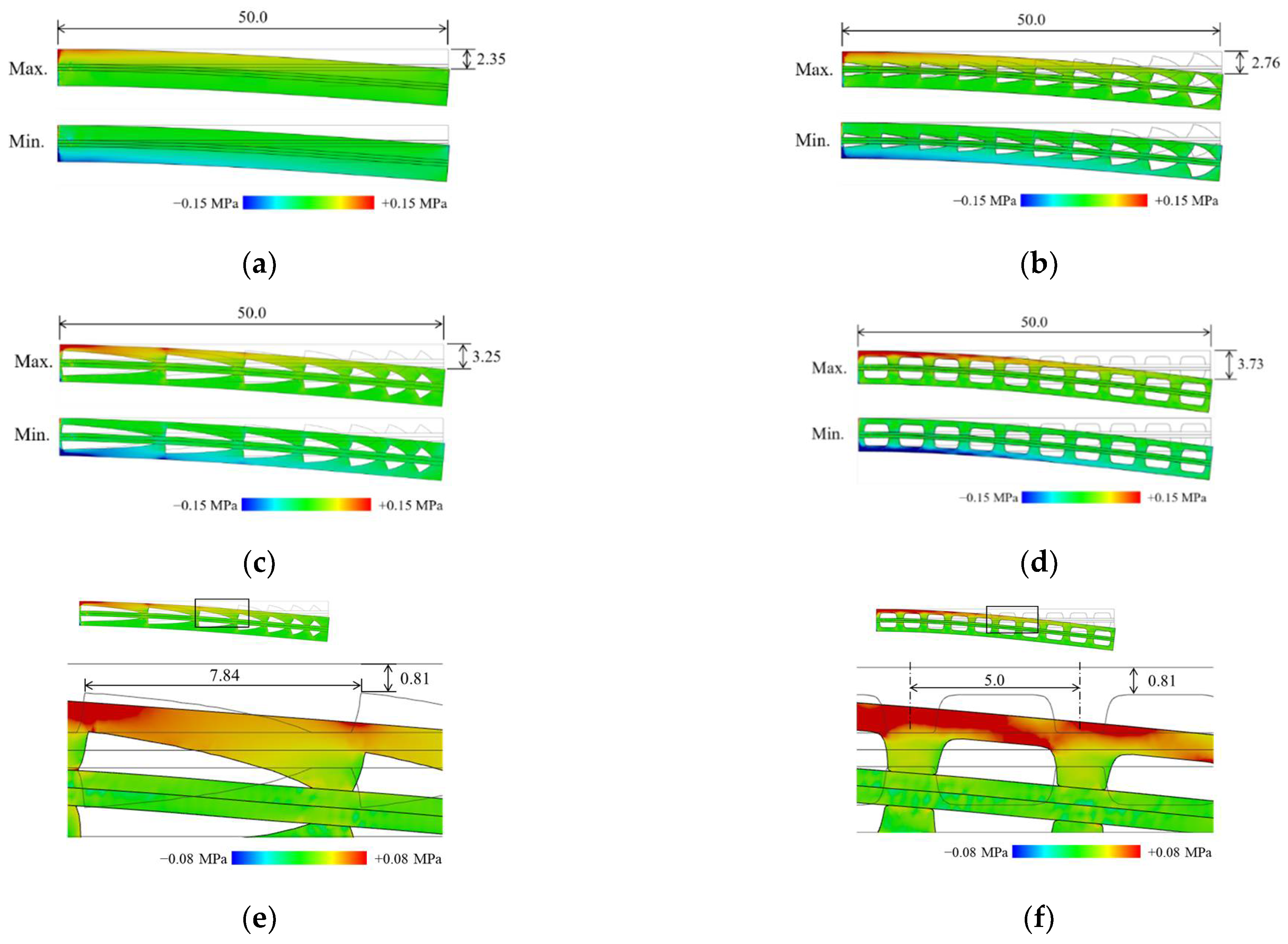
Figure 9.
Maximum and minimum principal stress in a low-stiffness state in the four conditions: Homogeneous (a), PSL-pitch (b), PSL-thickness (c) and Pillars (d). The load size was 0.01 N. The size of maximum vertical deflection in each condition is shown in (a–d).
Figure 9.
Maximum and minimum principal stress in a low-stiffness state in the four conditions: Homogeneous (a), PSL-pitch (b), PSL-thickness (c) and Pillars (d). The load size was 0.01 N. The size of maximum vertical deflection in each condition is shown in (a–d).


Figure 10.
A design of tunable stiffness organ-grasping device using the PSL-thickness pattern.
Publisher’s Note: MDPI stays neutral with regard to jurisdictional claims in published maps and institutional affiliations. |
© 2021 by the authors. Licensee MDPI, Basel, Switzerland. This article is an open access article distributed under the terms and conditions of the Creative Commons Attribution (CC BY) license (https://creativecommons.org/licenses/by/4.0/).
Share and Cite
MDPI and ACS Style
Kawase, T.; Sugino, T.; Onogi, S.; Kawashima, K.; Nakajima, Y. Improvement of a Tunable Stiffness Organ-Grasping Device by Design of a Wavy-Shaped Beam Structure. Appl. Sci. 2021, 11, 4581. https://doi.org/10.3390/app11104581
AMA Style
Kawase T, Sugino T, Onogi S, Kawashima K, Nakajima Y. Improvement of a Tunable Stiffness Organ-Grasping Device by Design of a Wavy-Shaped Beam Structure. Applied Sciences. 2021; 11(10):4581. https://doi.org/10.3390/app11104581
Chicago/Turabian StyleKawase, Toshihiro, Takaaki Sugino, Shinya Onogi, Kenji Kawashima, and Yoshikazu Nakajima. 2021. "Improvement of a Tunable Stiffness Organ-Grasping Device by Design of a Wavy-Shaped Beam Structure" Applied Sciences 11, no. 10: 4581. https://doi.org/10.3390/app11104581
Note that from the first issue of 2016, this journal uses article numbers instead of page numbers. See further details here.