1. Introduction
Alumina ceramics have found, for a long time, several important technological applications in optical [
1] and microelectronic components [
2] as protective, decorative, wear-resistant, solid-state device applications [
3,
4] and anticorrosion coatings [
5,
6,
7], due to their chemical inertness, good mechanical strength and high hardness, transparency and good insulating properties [
8].
In particular, high-temperature applications represent a new challenge for alumina ceramic joints in many fields [
9], especially for complex-shaped alumina ceramic components. It has been found that joining ceramics to themselves, or to metals, can be achieved by direct solid-state diffusion [
10], joining with metallic interlayers [
11] and joining using glass or glass–ceramic interlayers [
9,
12,
13]. These processes depend on solid-state diffusion and the interface that is formed at high pressures and high temperatures. A high bonding temperature, high bonding load and excellent surface finish [
9] are generally required for joining ceramics. Some problems reported are the low resistance to oxidation at high temperatures, in addition to relatively long processing times at high temperatures to ensure sufficient mutual diffusion.
Joining with glass and glass–ceramic fillers is more appropriate due to the excellent chemical compatibility and matched coefficient of thermal expansion (CTE) between glass filler and ceramics [
9,
12,
14]. CaO-Al
2O
3-SiO
2 have been employed as fillers for joining alumina ceramics [
15]. On the other hand, CaO-Al
2O
3-SiO
2-TiO
2 glass ceramics are also used [
9]. Among the advantages of using glass ceramics is the ability to obtain higher crystallinity, which allows the joint to be used at higher temperatures.
Several studies address the silica-stabilized zirconia, SiO
2-ZrO
2 glass–ceramic system, synthesized with the sol–gel method [
16,
17] and, like alumina, its applications are aimed at taking advantage of its thermal and optical properties, especially in thermal barrier coatings. To study new materials for joining alumina ceramics and new procedures, this work uses SiO
2-ZrO
2 glass–ceramic fillers and a CO
2 laser surface modification technique. The use of laser surface treatment techniques for the treatment of alumina coatings has been reported due to the high crystallinity that it confers on the material, and it has been shown that the required time is usually in the range of 1 to 15 min [
15]. Further, laser treatment represents an optical technique to detect phase transformation and densification of Al
2O
3 coatings. Laser surface modification of alumina coatings leads to the elimination of porosities and restoration of the stable phase [
3,
18].
This paper reports the spectroscopic properties of the Al2O3/SiO2-ZrO2 glass–ceramic filler on the brass substrate, where the laser surface modification causes a phase transformation.
2. Materials and Methods
The Al2O3/glass–ceramic composite coating was deposited onto brass substrates by the sol–gel process. Before deposition of the glass ceramic, an alumina interlayer (Al2O3) was deposited over the brass substrate using the standard air plasma spray technique to ensure the junction of the glass–ceramic layer. The brass substrates were cleaned by ultra-sound and alcohol without any special surface treatment. To achieve uniform porosity networks, we used a fused and crushed alumina powder (Metco 105&105SF).
For the preparation of the ZrO2-SiO2 glass ceramic, silica was synthesized via acid hydrolysis of traethylorthosilicate (TEOS, Merck 98% purity), ethanol (Sigma-Aldrich, 99.5% purity), de-ionized water (Amresco) and nitric acid as the catalyzer. The mixture was pre-hydrolyzed for 1 h at 70 °C, and it was maintained under these conditions for another 3 h to induce gelation. The molar ratio of TEOS:HNO3:EtOH:H2O was 0.1:0.00005:15.5:2.8. Pure zirconia was obtained from hydrolysis of two different precursors, Zr(C3H7O)4 (Sigma-Aldrich) and ZrClO2·8H2O (Merck). The mixture was kept at 50 °C for 1 h under constant agitation. This suspension was then added to the TEOS solution, resulting in a Zr:Si molar ratio of 90:10, and maintained at 70 °C for 1 h. The preparation was deposited onto Al2O3/brass substrates (1 in diameter) by the spin-coating technique (Laurell technologies ws-650 series). We established the rotation speed at 500 rpm and the rotation time at 50 s.
The Al
2O
3/ZrO
2-SiO
2 composite coating deposited on the brass substrate was then thermally treated at 850 °C for 60 min. Three samples were stabilized by a post-treatment using a CO
2 laser. This laser (Boye Laser HSLC-1206) of 10.6 µm wavelength with a beam diameter of 6 mm was used for laser modification of the surface. The power density of the CO
2 laser beam was 0.69 (SSZ01), 1.04 (SSZ02) and 1.38 W/cm
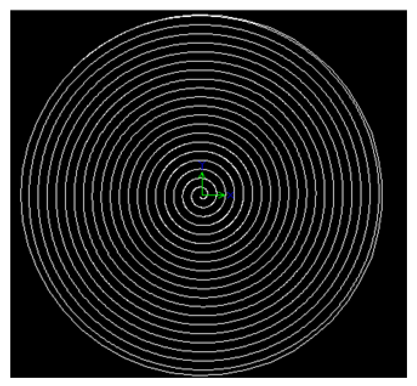
2 (SSZ03). The samples were positioned at around 50 cm from the laser output and exposed for 1 min. In
Figure 1, we present the computer-aided design (CAD) for the laser annealing path (1 in
2).
The photoluminescent signal was obtained by exciting the sample with the 488 nm line of an Argon laser. A 1 m focal distance spectrometer, with an 1800 g/mm grating and a thermoelectrically cooled CCD camera, was used to analyze the spectral response. The range for photoluminescence (PL) signal detection was between 550 and 900 nm.
The crystalline structure of the sample was investigated by X-ray diffraction (XRD). The diffractometer used was a Bruker D8 Advance with a vertical goniometer; the emission used was 1.5 angstrom radiation emitted by a Cu anode (Kα line) using 35 mA for the filament current and 30 kV for electron acceleration. The detector was a NaI crystal coupled to a photomultiplier tube. A graphite monochromator was located before the detector to eliminate the Cu-Kβ line. The divergence and antiscattering slits used were 0.6 mm each and 0.1 mm for the detector slit. The microstructure of the samples was studied using a scanning electron microscope (SEM, Phenom PROX, Cali, Colombia).
3. Results and Discussion
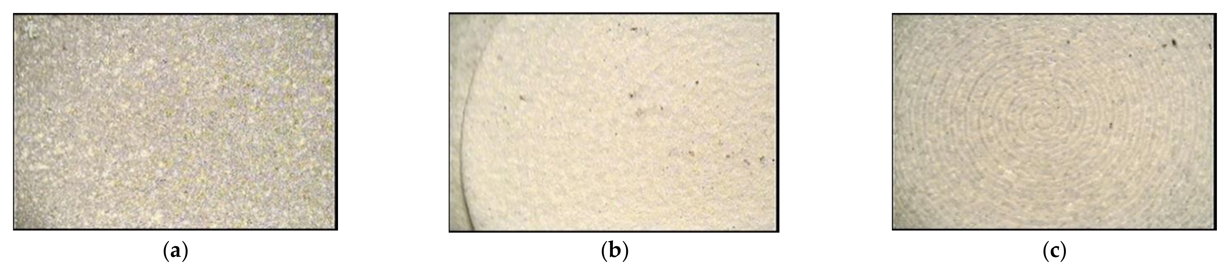
With the methodology described previously, we obtained regular coatings for all the thermally treated and laser-irradiated samples. The surface micrographs of the Al
2O
3/glass–ceramic coating are shown in
Figure 2. The path laser is evident in the laser annealing surfaces. The laser path’s definition on the surface is higher for higher laser density power (
Figure 2c).
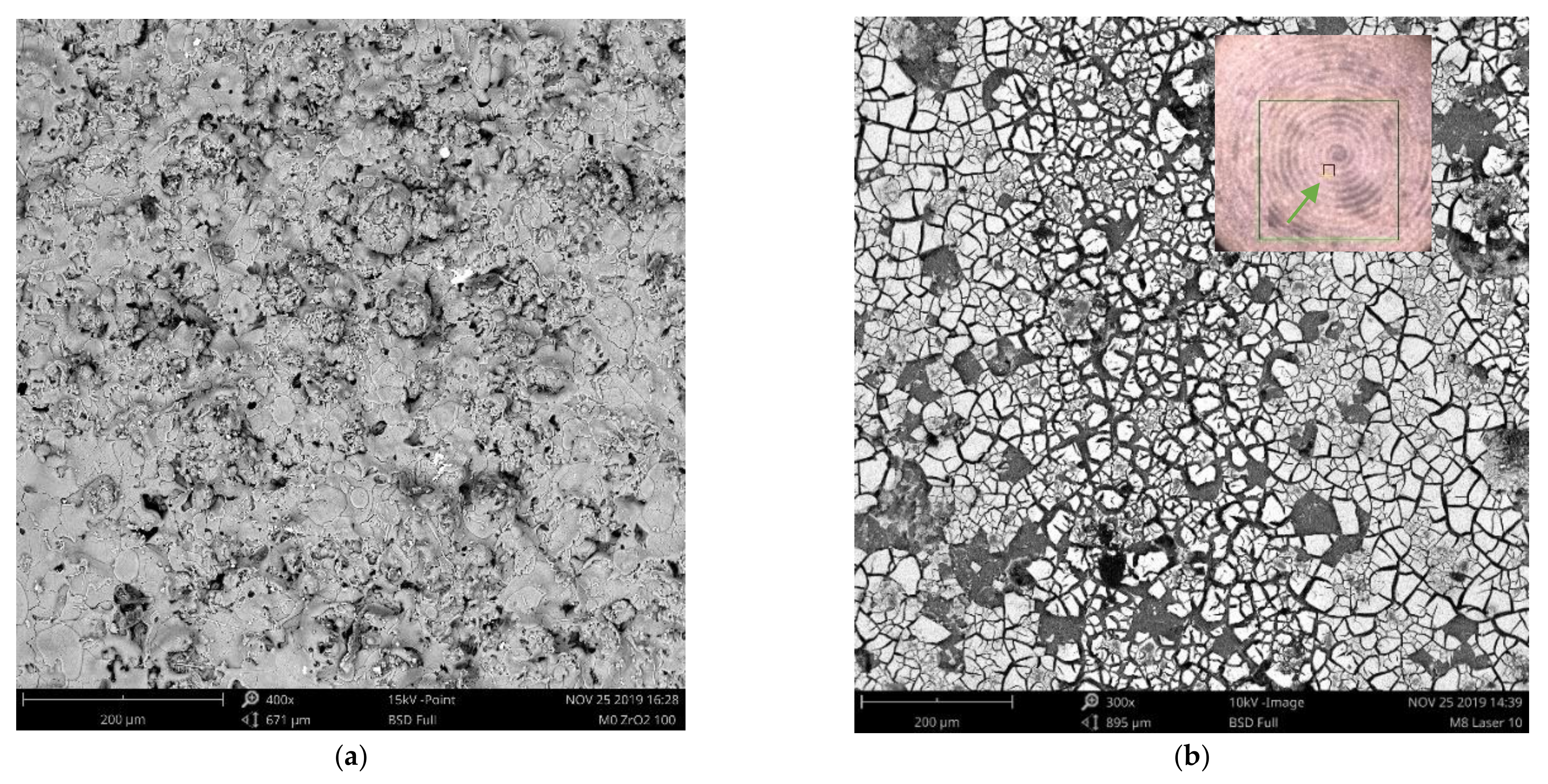
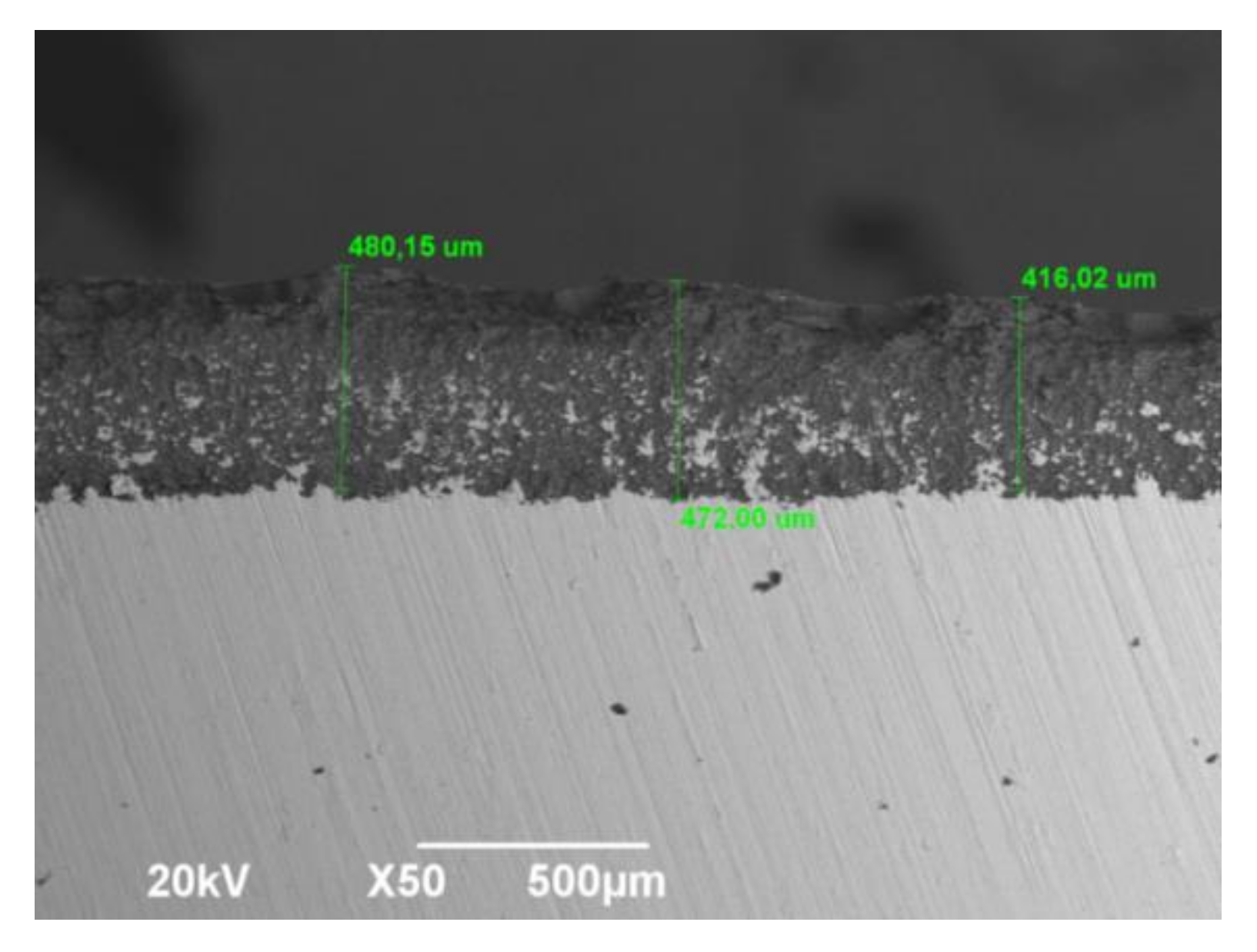
Figure 3 shows the surface morphology of the SSZ03 sample. The SEM images reveal a change in the surface profile created after laser irradiation on the Al
2O
3/glass–ceramic coating. The glass ceramic resembles a kind of broken glass on top of the alumina film. The coating layer’s morphology is not uniform in the microscopic range, and the cracked surface is probably due to differences in the thermal behavior. The thickness of the alumina coating with similar manufacturing parameters is between 400 and 500 μm, as shown in
Figure 4, in which the same authors have used Inconel 718 alloy as a substrate.
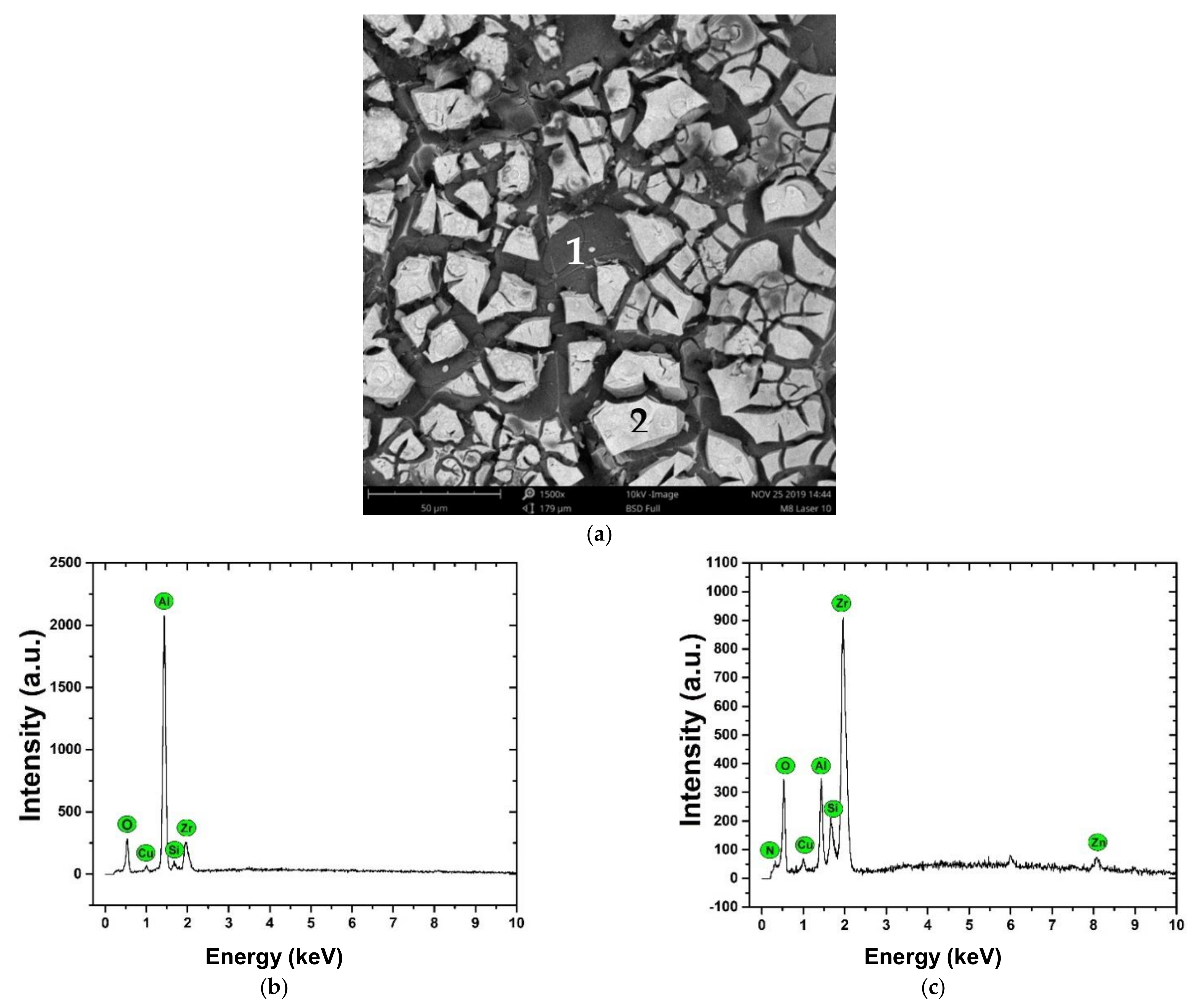
The SEM micrograph presented in
Figure 5a corresponds to the surface image over the Al
2O
3/glass–ceramic coating. In two different positions on the surface, the composition is described by the EDS spectra (
Figure 5b,c). It is evidenced that position 1 corresponds to the Al
2O
3 layer and position 2 to ZrO
2-SiO
2.
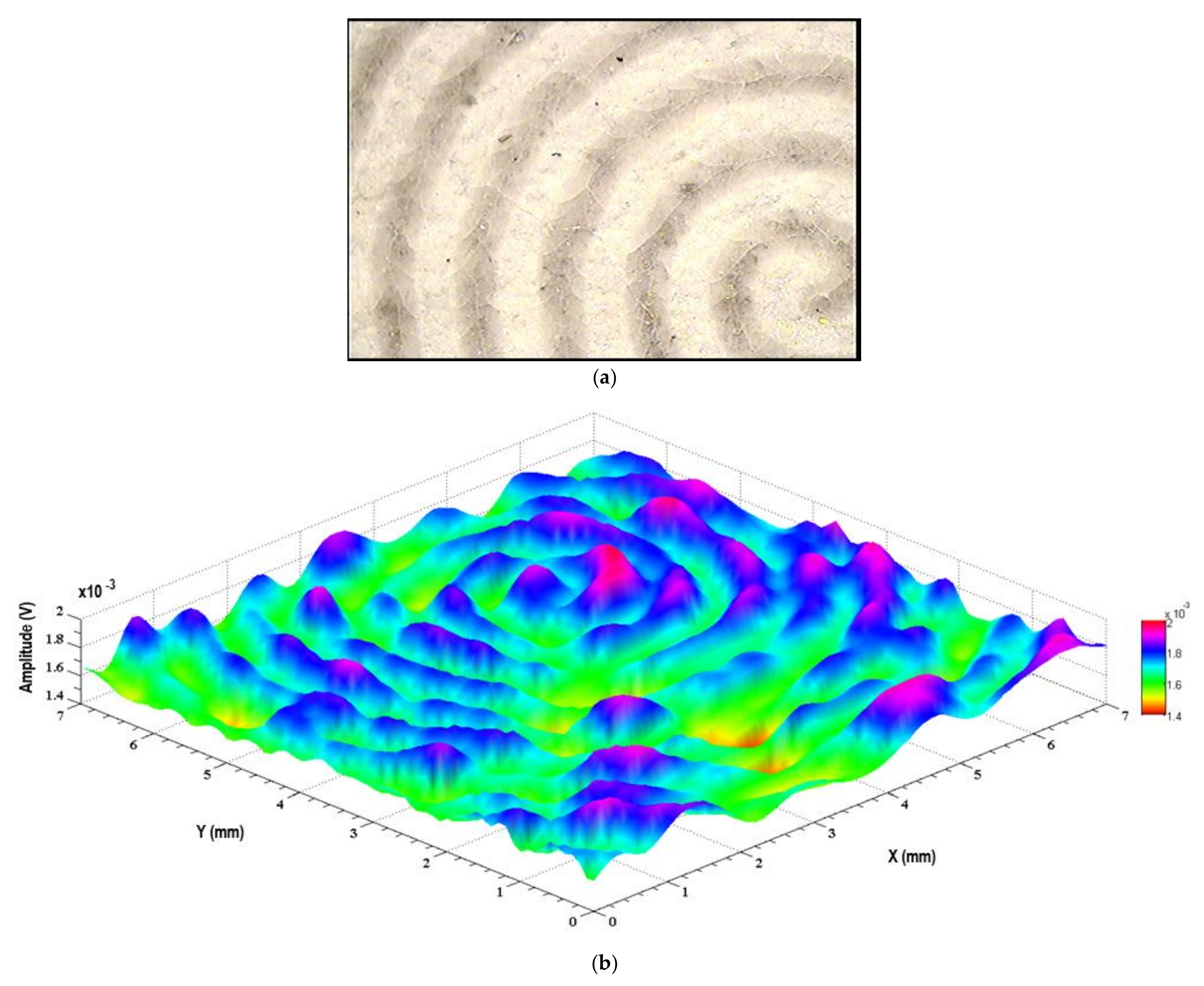
Figure 6a corresponds to an image of a sample surface annealed by irradiation using 1.38 W/cm
2 of laser power density and following the design mentioned above. The surface exhibits differences between sections which are irradiated and those not irradiated. The modifications induced by the laser are structural, and the thermo-optic response supports this statement.
Figure 6b shows the image obtained from the infrared emission induced by 520 nm radiation. In this map, the path pattern of the laser can be observed, showing the differences between the irradiated areas, as well as the homogeneity in the laser treatment carried out. This signal is associated with different non-radiative mechanisms and heat diffusion capabilities.
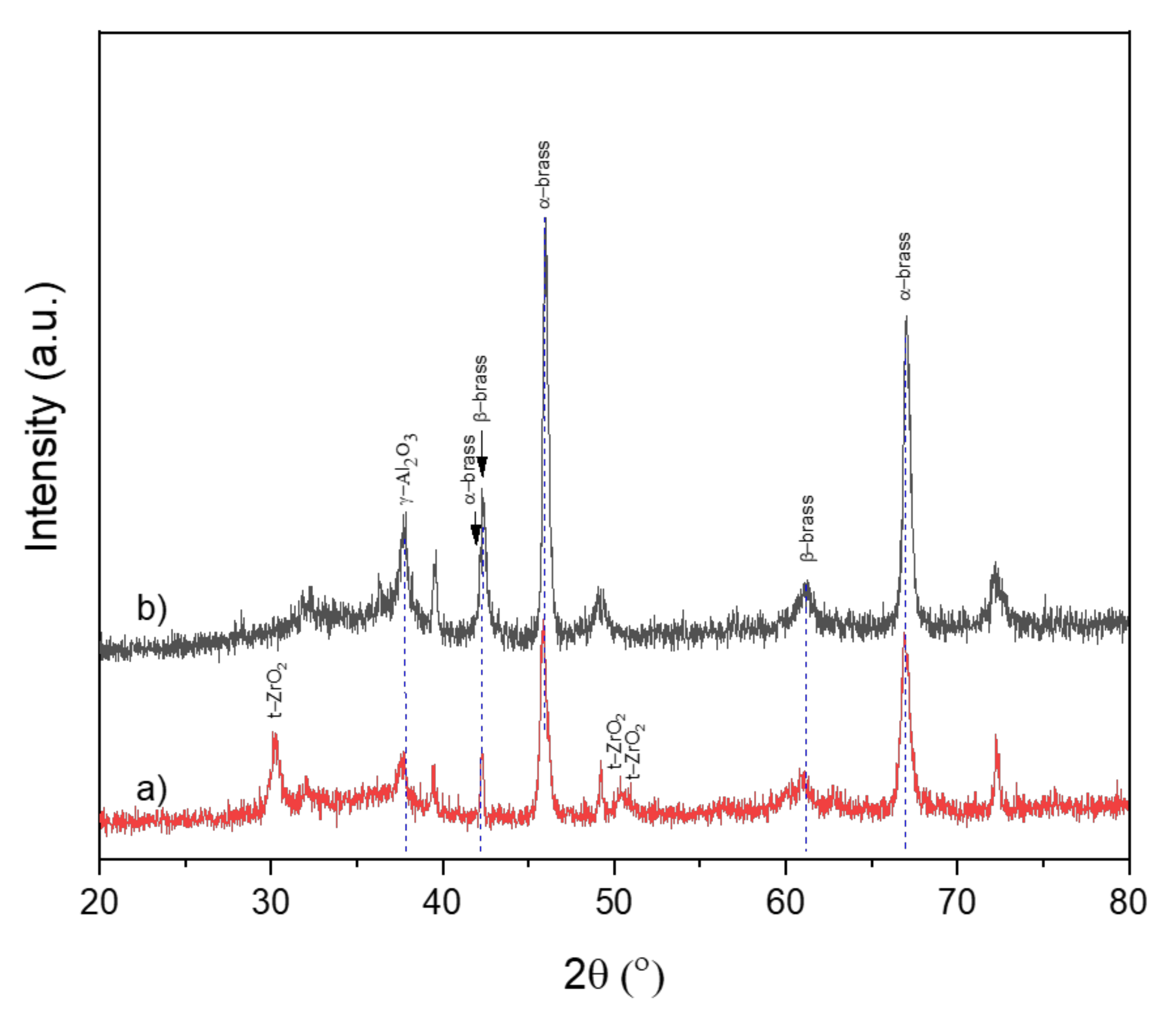
X-ray diffraction patterns of Al
2O
3/SiO
2-ZrO
2 and Al
2O
3 coatings both deposited on the brass substrate are presented in
Figure 7.
Figure 7a showed traces of tetragonal zirconia crystals at 30.2°, 50.4°, 50.7° (2θ) reported in the JCPDS-ICDD data (set no. 50-1089). The tetragonal ZrO
2 diffraction peaks correspond to the crystalline planes (011), (112) and (020), respectively, and the phase is conserved even when the sample reaches room temperature. Like the yttria-stabilized zirconia (YSZ), the most common material used as the ceramic layer, this demonstrates the well-known stabilizing effect in the ZrO
2 structure, promoting the formation of high-purity tetragonal zirconia [
19,
20,
21]. On the other hand, although the Al
2O
3/brass substrate sample displayed both α-brass and β-brass phases, compared with the Al
2O
3/SiO
2-ZrO
2/brass substrate, only α-brass was still observed [
22]. This indicates that the β-brass is present or formed when the Al
2O
3 is deposited (γ-Al
2O
3), and when glass–ceramic and thermal treatment are used, this phase is transformed into α-brass.
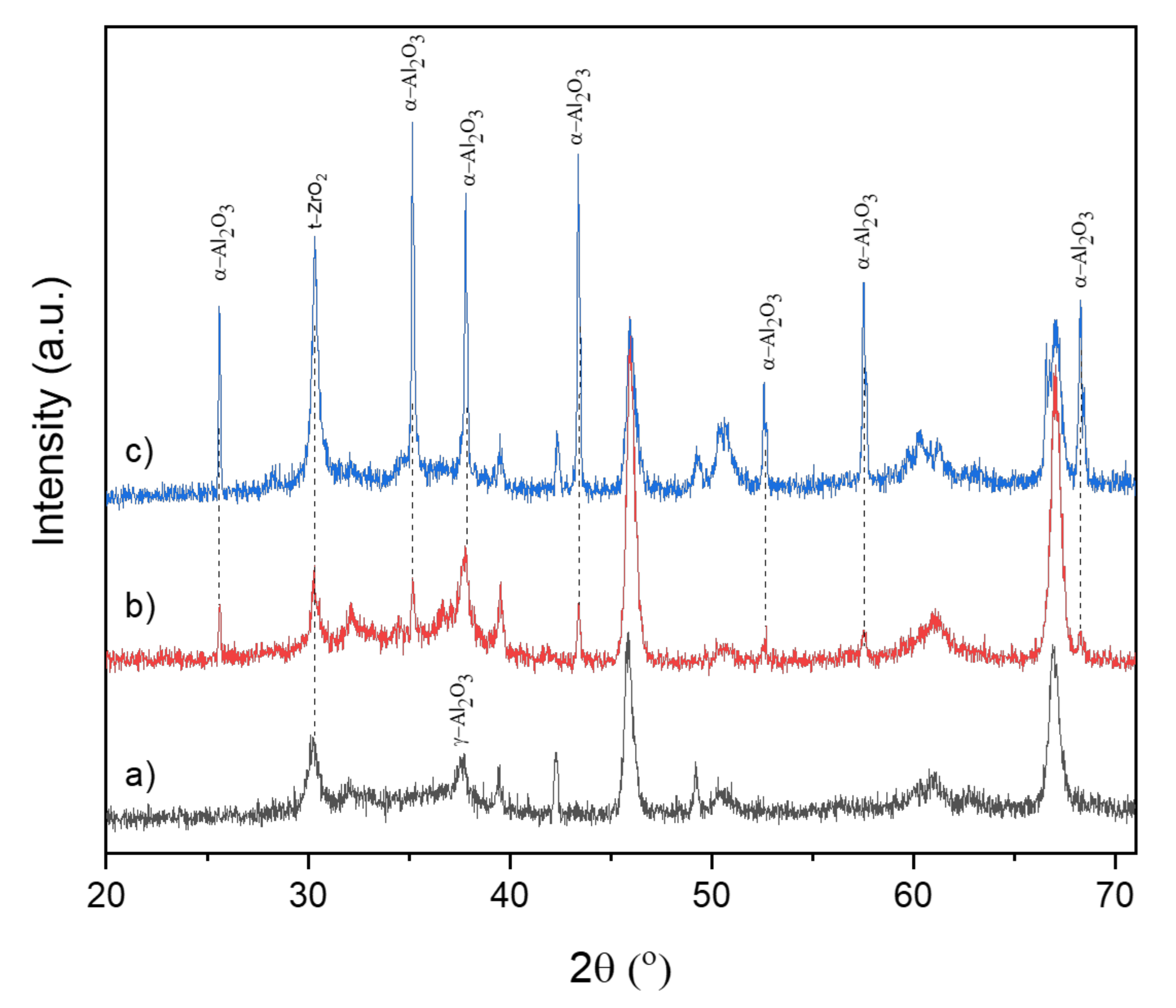
Figure 8 shows the X-ray diffraction patterns for the Al
2O
3/glass–ceramic composite coating system with different post-annealing treatments.
Figure 8a shows only the sample annealed at 850 °C at 60 min without any laser post-annealing;
Figure 8b shows the sample annealed at 850 °C at 60 min and under a CO
2 laser using 0.69 W/cm
2 power density for 1 min;
Figure 8c shows the sample annealed at 850 °C and under a CO
2 laser using 1.04 W/cm
2 power density for 1 min. All spectra display evidence of ZrO
2 formation, which is stable at ambient temperature. It is important to note that it was possible to obtain stable tetragonal ZrO
2 in the SiO
2-ZrO
2 coating by spin-coating and the thermal treatment applied at 850 °C for 60 min. The fitting procedure of the diffractograms indicates that the dominant structure is the tetragonal phase for ZrO
2, especially when CO
2 laser irradiation energy is increased (to see 2θ = 30.2°).
The sample annealed at 850 °C for 60 min (
Figure 8a) in the oven shows differences from the same sample with CO
2 laser post-annealing using 0.69 W/cm
2 (
Figure 8b) and 1.04 W/cm
2 (
Figure 8c) power density for 1 min. In
Figure 8a, the as-sprayed γ-Al
2O
3 is in a metastable phase, which is due to the rapid cooling rate of the process of plasma spraying, wherein alumina powder injected into the high temperature plasma is melted and entrained in the gas stream and is then accelerated and impinges on the substrate to form the coating [
23]. CO
2 laser annealing allows the transformation of γ-Al
2O
3 into thermodynamically stable α-Al
2O
3, this transformation being more visible at higher power densities.
Figure 8b,c show the XRD patterns typical of the stable corundum structure reported in JCPDS-ICDD data (set no. 46-1212).
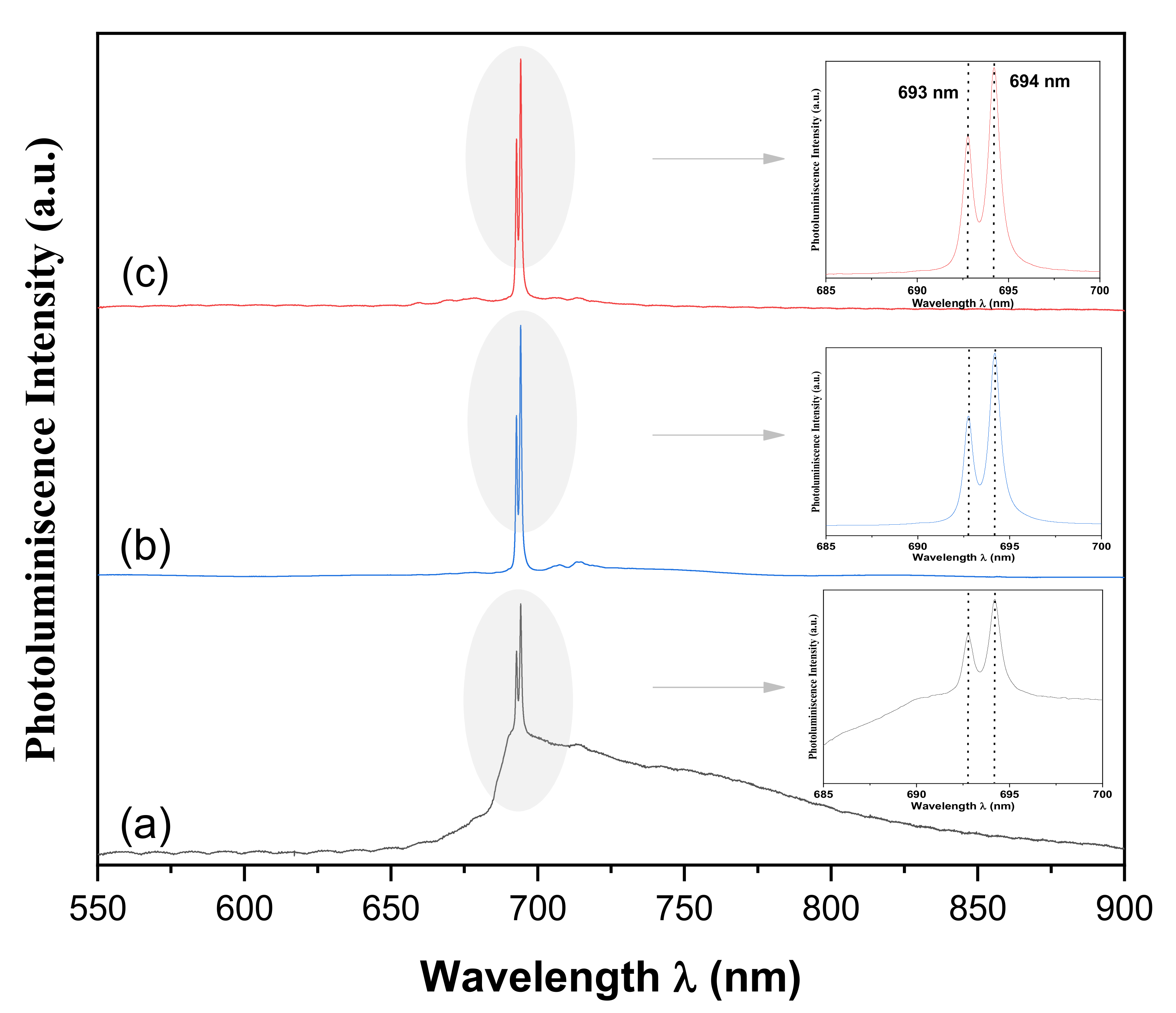
Figure 9 shows the PL spectra of SiO
2-ZrO
2/Al
2O
3 coatings without laser post-annealing and annealed for 1 min with different laser power densities: 0.69, 1.04, 1.38 W/cm
2. In this figure, the effect of laser power on the optical response is shown. All annealed samples exhibit a doublet at around 694 nm and broad and weak emission bands at lower energies, in which intensities and sharpness are enhanced as the laser power increases. The origin of these emission bands is not yet established. We found reports that the spectral emission at higher energies is due to the F+ center (330 and 415 nm). Chromium impurity in the Al
2O
3 lattice is characterized by two bands of absorption (3.1 and 2.2 eV), and one sharp emission structure peaked at 1.8 eV (696 nm), quite near the emission peak obtained by PL in this work [
4,
22]. According to this report, for the materials involved in the Al
2O
3/glass–ceramic composite coatings, the PL emission is associated with silica and zirconia in the Al
2O
3 bond coat.
4. Conclusions
In this paper, we report the crystallization and the influence of laser surface modification on the crystalline phases and optical response of Al2O3/glass–ceramic coatings. The ZrO2-SiO2 glass ceramic on alumina coatings prepared using the sol–gel technique, deposited under the experimental conditions used in this study, can be used for applications where a more stable alpha-alumina structure is required. This is due to the zirconia incorporated in the system maintaining its tetragonal phase at room temperature. This stable tetragonal ZrO2 phase at room temperature was obtained using annealing in an oven at 850 °C in the Al2O3/SiO2-ZrO2 composite coating.
Additionally, the results show that the use of CO2 laser annealing allows the identification of the spectroscopic properties of the studied system. In this sense, different power densities of 0.69 W/cm2, 1.04 W/cm2 and 1.38 W/cm2 were used to identify these properties. The annealing for 1 min allows the photoluminescence of the glass–ceramic system with optical emission to exhibit an intense double peak at 693 nm (1.789 eV) and 694 nm (1.786 eV) and weaker emission at lower energies. According to the surface micrographs and EDS analysis, the optical response is probably due to Al2O3, with a weak contribution of the ZrO2-SiO2 glass ceramic at lower energies. Although the study had a very important focus on the phase transformation of alumina associated with heat treatment in furnaces and lasers, it can be shown that the entire studied system has a good response to CO2 laser annealing, since emission is well defined; thus, it could be of interest for various optical applications.


 ,
, 


