
Cranial Implant Design Applying Shape-Based Interpolation Method via Open-Source Software
by
 , , , and
Johari Yap Abdullah
1,* ,
,
Abdul Manaf Abdullah
1,
Low Peh Hueh
2,
Adam Husein
1,
Helmi Hadi
3 and
Zainul Ahmad Rajion
4,* 1
School of Dental Sciences, Health Campus, Universiti Sains Malaysia, Kubang Kerian 16150, Kelantan, Malaysia
2
Department of Neurosurgery, Sarawak General Hospital, Kuching 93586, Sarawak, Malaysia
3
School of Health Sciences, Health Campus, Universiti Sains Malaysia, Kubang Kerian 16150, Kelantan, Malaysia
4
Kulliyyah of Dentistry, IIUM Kuantan, Jalan Sultan Ahmad Shah, Bandar Indera Mahkota, Kuantan 25200, Pahang, Malaysia
*
Authors to whom correspondence should be addressed.
Appl. Sci. 2021, 11(16), 7604; https://doi.org/10.3390/app11167604
Submission received: 13 June 2021
/
Revised: 2 August 2021
/
Accepted: 17 August 2021
/
Published: 19 August 2021
(This article belongs to the Special Issue New Trends in Biosciences)
Abstract
:Reconstructing a large skull defect is a challenge, as it normally involves the use of sophisticated proprietary image processing and expensive CAD software. As an alternative, open-source software can be used for this purpose. This study aimed to compare the 3D cranial implants reconstructed from computed tomography (CT) images using the open-source MITK software with commercial 3-matic software for ten decompressive craniectomy patients. The shape-based interpolation method was used, in which the technique of segmenting every fifth and tenth slice of CT data was performed. The final design of patient-specific implants from both software was exported to STL format for analysis. The results of the Kruskal–Wallis test for the surface and volume of cranial implants designed using 3-matic and the two MITK techniques showed no significant difference, p > 0.05. The results of the Hausdorff Distance (HD) and Dice Similarity Coefficient (DSC) analyses for cranial implants designed using 3-matic software and the two different MITK techniques showed that the average points distance for 3-matic versus MITK was 0.28 mm (every tenth slice) and 0.15 mm (every fifth slice), and the similarity between 3-matic and MITK on every tenth and fifth slices were 85.1% and 89.7%, respectively. The results also showed that the open-source MITK software is comparable with the commercial software for designing patient-specific implants.
1. Introduction
The three-dimensional (3D) reconstruction of the craniofacial region is a challenge if involving a very large defect, and it requires the use of sophisticated proprietary image processing and expensive computer-aided design (CAD) software. Previously, the surgical procedure for managing large defects of the skull was complicated as it must be performed manually based on two-dimensional (2D) imaging, namely the shaping, modelling, and placement of the implant, which is made of bone grafts, bone cement, or titanium meshes. Using this conventional method resulted in long and complex operations with poor aesthetic results. The manual process is very labour-intensive and expensive [1]. With the advance in computer and additive manufacturing (AM) technology, an implant that exactly fits the defect can be manufactured pre-operatively from the radiographic data obtained from CT scans.
Studies reported the advantages of using several different computer-aided designs and computer-aided manufacturing (CAD/CAM) platforms [2], which resulted in perfectly fitted implants, less surgery time, and better aesthetic results [3]. Functional and aesthetically placed patient-specific cranial implants are extremely important for patients with large cranial defects. Therefore, pre-operative fabrication of the implants is recommended [4] to ensure minimal adjustment during surgery, which would then translate to lower surgical cost and time, as the implants would fit nicely into the defect. Rapid developments in medical imaging and advances in CAD/CAM improved the quality of implants, resulted in improved aesthetic outcomes, and minimised operation time, blood loss, and risk of infection [5,6]. Patient-specific implants can be produced in any size with an accurate fit using this technology [7]. The creation of the cranial implant with optimal size, shape, and mechanical properties prior to the surgical procedure reduces the operation time and complexity [8]. The main advantage of using CAD/CAM is a better outcome and aesthetic of the implant; therefore, it can be successfully used in the repair of a defect [9]. Using CAD software enables the users to automatically check if the design is within specification. It also enables users to view designs at an earlier stage in the design process. However, CAD software often consumes large amounts of computer processing power. This requires high-quality computer hardware that can be costly, on top of the price of the CAD software [10]. The cost of hardware and software is a significant disadvantage of the CAD/CAM and a major barrier to adopting this technology, particularly for institutions with a limited budget. Another disadvantage of the CAD/CAM technology is the complexity of the software. As the CAD software advances, it becomes more flexible and adaptable and could have much more functions. However, this comes at the cost of making the software more complex. This complexity makes it more difficult for first-time users to master the software. Combined with the cost of training personnel in CAD/CAM technologies, this complexity represents another disadvantage of CAD/CAM.
Another technique is the mirror reconstruction method, by replicating the missing bone segment using mirrored healthy skull on the other side where the skull was assumed to be symmetrical along its mid-sagittal plane. The “Boolean” operation, which refers to subtracting the mirrored bone from the combined healthy and defected portions of the skull, was then used to cut and obtain the cranial implant that fits perfectly into the defect. The advantage of the mirror image reconstruction method is that it generates the customised cranial implant with a thickness exactly to the thickness of the skull bone, which was about 2.5 mm [11]. Lo et al. [12] used commercial AnalyzeTM software to perform the mirror-imaging function to create cranial implants by using the intact contralateral anatomy as a template for patients with traumatic injuries secondary to MVA. However, their findings showed that the mirror image reconstruction method could not be used if the portion of the defect crossed the midline. This finding is supported by Senck et al. [13]; they too confirmed that the mirror-imaging technique could not be applied if the skull defect extends into the mid-sagittal region. Therefore, another method for cranial reconstruction of skull defects was studied. One of the possible methods to create a patient-specific cranial implant is by using the shape-based interpolation method, which is available in open-source MITK software [14]. To the best of our knowledge, there are no studies applying the shape-based interpolation method for the reconstruction of a cranial implant using open-source software.
2. Methods
The research tools used in this study were commercial and open-source software installed on a Dell Precision T7500 workstation at the Craniofacial Imaging and Addictive Manufacturing Laboratory, School of Dental Sciences, Universiti Sains Malaysia. The commercial software as a reference (gold standard) are Mimics software (v17.0) and 3-matic software (v9.0), both from Materialise NV, Heverlee, Belgium. Mimics software was used to process the computed tomography (CT) images and reconstructed them into 3D models. These models were used to design the cranial implants using the 3-matic software and later exported to standard tessellation language (STL) format for comparison. Ten patients with post decompressive craniectomy (DC) were enrolled for this study. The study was approved by The Human Research Ethics Committee, Universiti Sains Malaysia (HREC; USMKK/PPP/JEPeM [259.3(2)]; FWA Reg. No: 00007718; IRB Reg. No: 00004494). Informed consent was obtained from all subjects involved in the study. They were scanned using the Siemens Somatom Definition AS+ 128-slice (Siemens, Erlangen, Germany) at the Radiology Department, Hospital USM, prior to the DC surgery. Contiguous CT images were acquired at a slice thickness of 1 mm. The slice series had a matrix of 512 × 512 pixels each.
Ten cranial implants were designed using the commercial 3-matic software (v9.0) as the gold standard, and another ten cranial implants were designed using the open-source MITK Workbench 2016.11 software (German Cancer Research Center, Heidelberg, Germany). Both designs were from the same group of patients and saved in STL format. The implant designed using open-source MITK software was then compared to the implant designed using the gold standard 3-matic software to evaluate its accuracy.
2.1. Design of Cranial Implants Using 3-Matic Software
The 3-matic software was used to design the cranial implant using the mirror image reconstruction method [11]. In this method, the skull was divided along the mid-plane, and then the healthy bone was mirrored to the defective side with reference to the mid-plane. Merging and wrapping operations were performed to overcome the gaps and discontinuous surfaces. Next, a Boolean operation was performed to cut and remove the selected cranial implant. This patient-specific cranial implant was saved in STL format and tested on the defect skull for fitting evaluation (Figure 1).
2.2. Design of Cranial Implants Using MITK Software
As an alternative to commercial 3-matic software, MITK was used to design the patient-specific cranial implant using a shape-based interpolation method. After the CT data of defected skull were loaded, a new “Segmentation” was created to design the cranial implant. Next, the paint size 14 in the 2D Tools box (red rectangle) was used to draw the line along the defective skull, as shown in Figure 2.
The line was drawn while the left side of the mouse was held in a clicked position; the mouse was moved along the perimeter of the defect skull following the curvature of the healthy skull. The axial slice was enlarged for segmentation editing. If the line was over drawn, the “2D Tools” (red rectangle in Figure 3) were used to edit the line, either by using the “Erase” tool to delete the whole line or the “Wipe” tool to delete part of the line. The “Wipe” tool has different sizes of circles, similar to the size of the “Paint” tool. The “Add” and “Subtract” tools were also used to add or remove certain parts of the line.
The size of “Paint” tool was used as a thickness indicator before drawing the cranial implant by choosing the right thickness of the implant before drawing, based on the healthy part of the skull. The “Paint” size in millimetres was 5.95 mm, 5.10 mm, 4.25 mm, 3.40 mm, and 2.55 for the size of 14, 12, 10, 8, and 6, respectively.
A line was drawn to represent the thickness of the implant to cover the defect. The first line to be drawn may be selected from the most top or most bottom of the CT data axial slices, following which the same line is drawn on every tenth or fifth slice. In this example, the total axial slices within the defective area are 132 slices (slice no 91 to 223). Starting with slice no 91, every tenth slice was selected to draw the line for implant design, one by one, until slice 221, which were 91, 101, 111, 121, 131, 141, 151, 161, 171, 181, 191, 201, 211, and 221. The total number of slices involved for shape-based interpolation was 14 slices. Figure 4 shows the example of a line drawn in axial slice numbers 151, 161, and 171.
Once the line drawing of every tenth axial slice was performed, the 2D interpolation was executed applying the shape-based interpolation method, and the 3D cranial implant was successfully created, but not all surfaces of implants were reconstructed due to under-interpolation as shown in Figure 5.
As the selected axial slice was performed at every tenth slice, some areas were not interpolated; thus, holes could be seen on the implant. However, it can still be edited on the axial slice to cover the hole or defect of the interpolation, and the redo process can be carried out, as shown in Figure 6.
Alternatively, another method of selecting every fifth slice for interpolation was tested, as shown in Figure 7.
When every fifth slice interpolation method was performed, the slices involved were 91, 96, 101, 106, 111, 116, 121, 126, 131, 136, 141, 146, 151, 156, 161, 166, 171, 176, 181, 186, 191, 196, 201, 206, 211, 216, and 221. The total number of slices was 27. The result of the patient-specific cranial implant using the shape-based interpolation method on every tenth slice and fifth slice were saved in STL format and exported to STL format, as shown in Figure 8.
The patient-specific cranial implants designed obtained from 3-matic and MITK software were then evaluated for their geometric accuracy [15,16] using Hausdorff Distance (HD) and Dice Similarity Coefficient (DSC) on open-source CloudCompare software (version 2.10.1; GPL software) [17] as shown in Figure 9.
2.3. Statistical and Geometric Analyses
For the statistical analysis, the surface area and volume of the ten cranial implants were compared between 3-matic software and two different techniques (shape-based interpolation every tenth and fifth slices) of MITK software using the Kruskal–Wallis test with the Statistical Package for the Social Science (SPSS) version 24.0. Tests of normality and homogeneity were carried out and confirmed using the Kolmogorov–Smirnov test. A statistical significance value was set at p < 0.05. The accuracy of the cranial implants designed using MITK software was compared with the cranial implants designed using 3-matic software. The comparison was made using metrics based on 3D geometry, which were HD and DSC using then open-source CloudCompare software (version 2.10.1).
3. Results
The results of the Kruskal–Wallis test for cranial implants surface and volume designed using 3-matic software and two different techniques (shape-based interpolation every tenth and fifth slices) of MITK software are shown in Table 1.
There were no significant differences for cranial implant surface and cranial implant volume with p > 0.05.
The results of HD for patient-specific cranial implants designed using 3-matic software and two different techniques (shape-based interpolation every tenth and fifth slices) of MITK software are shown in Table 2.
Based on HD analysis, the average points distance for 3-matic software vs. MITK on every tenth slice was 0.28 mm, and for 3-matic software vs. MITK on every fifth slice, it was 0.15 mm.
The results of DSC for patient-specific cranial implants designed using 3-matic software and two different techniques (shape-based interpolation every tenth and fifth slices) of MITK software are shown in Table 3.
Based on DSC analysis, the similarities were 85.1% for MITK on every tenth slice and 3-matic and 89.7% for MITK on every fifth slice and 3-matic.
4. Discussion
The 3-matic software and MITK were both used to design patient-specific cranial implants. The implant designed using MITK was produced applying the shape-based interpolation method with two different techniques, namely the tenth and fifth slices segmentation. HD and DSC analyses comparing all three designs (produced using the 3-matic, MITK tenth slice, and MITK fifth slice) showed no significant differences among them. The Kruskal–Wallis analyses on the surface area and volume of the patient-specific implants also showed no significant differences. Based on these findings, the patient-specific cranial implants produced using the gold standard 3-matic software and open-source MITK are comparable.
It was reported that HD values less than 3 mm and DSC values above 0.80 were considered adequate [18]. It was also reported that the DSC value of 0.86 was considered accurate [19]. The HD value from this study for 3-matic vs. MITK was 0.28 mm (every 10th slice) and 0.15 mm (every 5th slice), suggesting that the cranial implants reconstructed using MITK software are accurate or similar to the gold standard.
The cranial implants reconstructed using the shape-based interpolation method via open-source MITK software have a DSC value of 0.851 (every 10th slice) and 0.897 (every 5th slice) when analysed against the gold standard. This showed that the cranial implants created using the shape-based interpolation method via MITK on every tenth slice and every fifth were 85.1% and 89.7%, similar to the gold standard, respectively.
The patient-specific cranial implants were successfully designed using commercial 3-matic software and an open-source MITK software applying a shape-based interpolation method; both showed high similarity in the surface area and volume. The measurements demonstrated no differences using HD analyses and good similarity using DSC analyses for all ten patient-specific cranial implants. The conclusion from these findings was that designs created using open-source software provided similar results to commercial software.
In conclusion, this study confirmed that the shape-based interpolation method via open-source MITK software gave comparable results in the design of patient-specific cranial implants compared to the commercial gold standard 3-matic software. This confirms that the simpler shape-based interpolation method could be used to design patient-specific cranial implants instead of complicated CAD software. The inclusion of this software in a clinical setting would save clinicians’ time in pre-operative planning and the cost in patient management.
Author Contributions
Conceptualisation, J.Y.A., A.M.A. and L.P.H.; methodology, J.Y.A.; software, J.Y.A.; validation, H.H., A.H. and Z.A.R.; formal analysis, J.Y.A.; investigation, J.Y.A.; resources, Z.A.R.; data curation, J.Y.A.; writing—original draft preparation, J.Y.A.; writing—review and editing, J.Y.A. and A.M.A.; visualization, J.Y.A.; supervision, Z.A.R., A.H. and H.H.; project administration, J.Y.A.; funding acquisition, J.Y.A. All authors have read and agreed to the published version of the manuscript.
Funding
This study was made possible with partial funding from TDC Holdings Sdn Bhd through Universiti Sains Malaysia (304.PPSG.6150194/T152).
Institutional Review Board Statement
The study was approved by the Human Research Ethic Committee USM (HREC) (USMKK/PPP/JEPeM [259.3(2)]) (FWA Reg. No: 00007718; IRB Reg. No: 00004494).
Informed Consent Statement
Informed consent was obtained from all subjects involved in the study.
Data Availability Statement
Data are available upon request.
Acknowledgments
We thank Suzana Yahya from Craniofacial Imaging and Addictive Manufacturing Laboratory for assisting us in the laboratory and Mohd Firdaus Daud from the Radiology Department for assisting us with CT data retrieval.
Conflicts of Interest
The authors declare no conflict of interest.
References
- Salmi, M.; Tuomi, J.; Bjorkstrand, R.; Kontio, R.; Paloheimo, M.; Makitie, A.A.; Mesimaki, K.; Salo, J.; Paloheimo, K.S. Patient-specific reconstruction with 3D modeling and DMLS additive manufacturing. Rapid Prototyp. J. 2012, 18, 209–214. [Google Scholar] [CrossRef]
- Drstvensek, I.; Hren, N.I.; Strojnik, T.; Brajlih, T.; Valentan, B.; Pogacar, V.; Hartner, T.Z. Applications of Rapid Prototyping in CranioMaxilofacial Surgery Procedures. Int. J. Biol. Biomed. Eng. 2008, 2, 29–38. [Google Scholar]
- Mazzoli, A.; Germani, M.; Raffaeli, R. Direct fabrication through electron beam melting technology of custom cranial implants designed in a PHANToM-based haptic environment. Mater. Des. 2009, 30, 3186–3192. [Google Scholar] [CrossRef]
- Marreiros, F.M.; Heuze, Y.; Verius, M.; Unterhofer, C.; Freysinger, W.; Recheis, W. Custom implant design for large cranial defects. Int. J. Comput. Assist. Radiol. Surg. 2016, 11, 2217–2230. [Google Scholar] [CrossRef] [PubMed]
- Chen, S.T.; Chang, C.J.; Su, W.C.; Chang, L.W.; Chu, I.H.; Lin, M.S. 3-D titanium mesh reconstruction of defective skull after frontal craniectomy in traumatic brain injury. Injury 2015, 46, 80–85. [Google Scholar] [CrossRef] [PubMed]
- Zhao, L.; Patel, P.K.; Cohen, M. Application of Virtual Surgical Planning with Computer Assisted Design and Manufacturing Technology to Cranio-Maxillofacial Surgery. Arch. Plast. Surg. 2012, 39, 309–316. [Google Scholar] [CrossRef] [PubMed] [Green Version]
- Oh, J. Recent advances in the reconstruction of cranio-maxillofacial defects using computer-aided design/computer-aided manufacturing. Maxillofac. Plast. Reconstr. Surg. 2018, 40, 2. [Google Scholar] [CrossRef] [Green Version]
- Jardini, A.L.; Larosa, M.A.; Filho, R.M.; Zavaglia, C.A.; Bernades, L.F.; Lambert, C.S.; Calderoni, D.R.; Kharmandayan, P. Cranial reconstruction: 3D biomodel and custom-built implant created using additive manufacturing. J. Cranio-Maxillofac. Surg. 2014, 42, 1877–1884. [Google Scholar] [CrossRef]
- van der Meer, W.J.; Bos, R.R.M.; Vissink, A.; Visser, A. Digital planning of cranial implants. Br. J. Oral Maxillofac. Surg. 2013, 51, 450–452. [Google Scholar] [CrossRef]
- Nguyen, P.D.; Khechoyan, D.Y.; Phillips, J.H.; Forrest, C.R. Custom CAD/CAM implants for complex craniofacial reconstruction in children: Our experience based on 136 cases. J. Plast. Reconstr. Aesthet. Surg. 2018, 71, 1609–1617. [Google Scholar] [CrossRef]
- Moiduddin, K.; Darwish, S.; Al-Ahmari, A.; ElWatidy, S.; Mohammad, A.; Ameen, W. Structural and mechanical characterization of custom design cranial implant created using additive manufacturing. Electron. J. Biotechnol. 2017, 29, 22–31. [Google Scholar] [CrossRef]
- Lo, L.J.; Chen, Y.R.; Tseng, C.S.; Lee, M.Y. Computer-aided reconstruction of traumatic fronto-orbital osseous defects: Aesthetic considerations. Chang. Gung Med. J. 2004, 27, 283–291. [Google Scholar] [PubMed]
- Senck, S.; Coquerelle, M.; Weber, G.W.; Benazzi, S. Virtual reconstruction of a very large skull defects featuring partly and completely missing midsagittal planes. Anat. Rec. 2013, 296, 745–758. [Google Scholar] [CrossRef] [PubMed] [Green Version]
- Nolden, M.; Zelzer, S.; Seitel, A.; Wald, D.; Muller, M.; Franz, A.M.; Maleike, D.; Fangerau, M.; Baumhauer, M.; Maier-Hein, L.; et al. The Medical Imaging Interaction Toolkit: Challenges and advances: 10 years of open-source development. Int. J. Comput. Assist. Radiol. Surg. 2013, 8, 607–620. [Google Scholar] [CrossRef] [PubMed]
- Kim, H.; Monroe, J.I.; Lo, S.; Yao, M.; Harari, P.M.; Machtay, M.; Sohn, J.W. Quantitative evaluation of image segmentation incorporating medical consideration functions. Med. Phys. 2015, 42, 3013–3023. [Google Scholar] [CrossRef] [PubMed]
- Powell, K.A.; Liang, T.; Hittle, B.; Stredney, D.; Kerwin, T.; Wiet, G.J. Atlas-Based Segmentation of Temporal Bone Anatomy. Int. J. Comput. Assist. Radiol. Surg. 2017, 12, 1937–1944. [Google Scholar] [CrossRef] [PubMed]
- CloudCompare. (version 2.10.1) [GPL Software]. Available online: https://www.danielgm.net/cc/ (accessed on 2 December 2018).
- Hvid, C.A.; Elstrom, U.V.; Jensen, K.; Alber, M.; Grau, C. Accuracy of software-assisted contour propagation from planning CT to cone beam CT in head and neck radiotherapy. Acta Oncol. 2016, 55, 1324–1330. [Google Scholar] [CrossRef] [PubMed] [Green Version]
- Polan, D.F.; Brady, S.L.; Kaufman, R.A. Tissue segmentation of Computed Tomography images using a Random Forest algorithm: A feasibility study. Phys. Med. Biol. 2016, 61, 6553–6569. [Google Scholar] [CrossRef] [PubMed]
Figure 1.
Fitting evaluation of patient-specific cranial implant on the defect skull.

Figure 2.
The “Paint” tool was used to draw the line along defective skull.
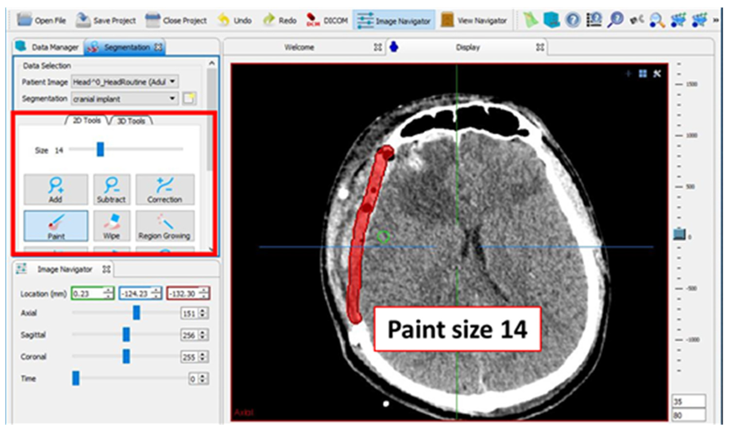
Figure 3.
The axial slice of the segmentation was enlarged to view the line drawn and for editing purposes.
Figure 3.
The axial slice of the segmentation was enlarged to view the line drawn and for editing purposes.
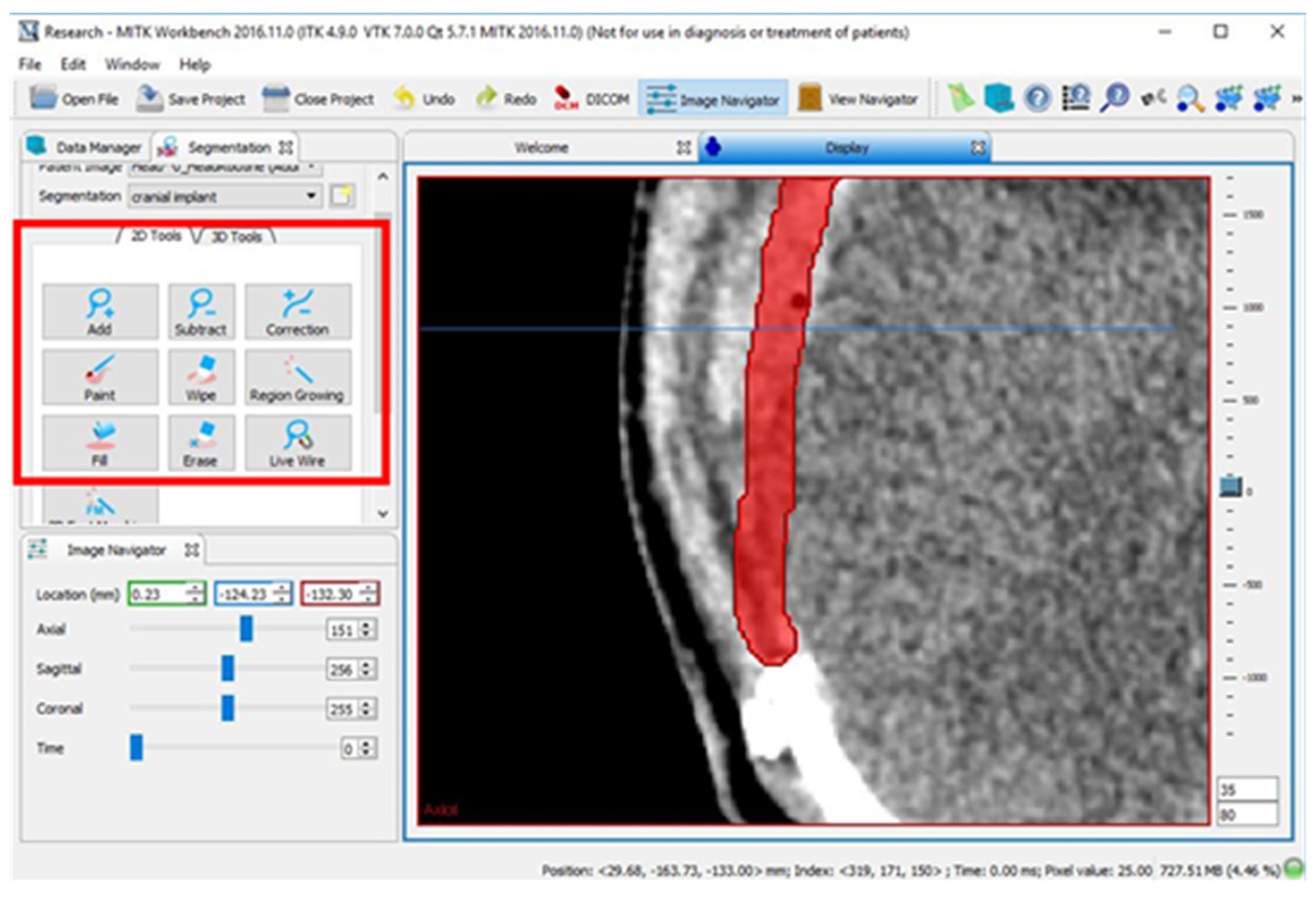
Figure 4.
Slices (A) 151, (B) 161, and (C) 171 of every tenth slice.
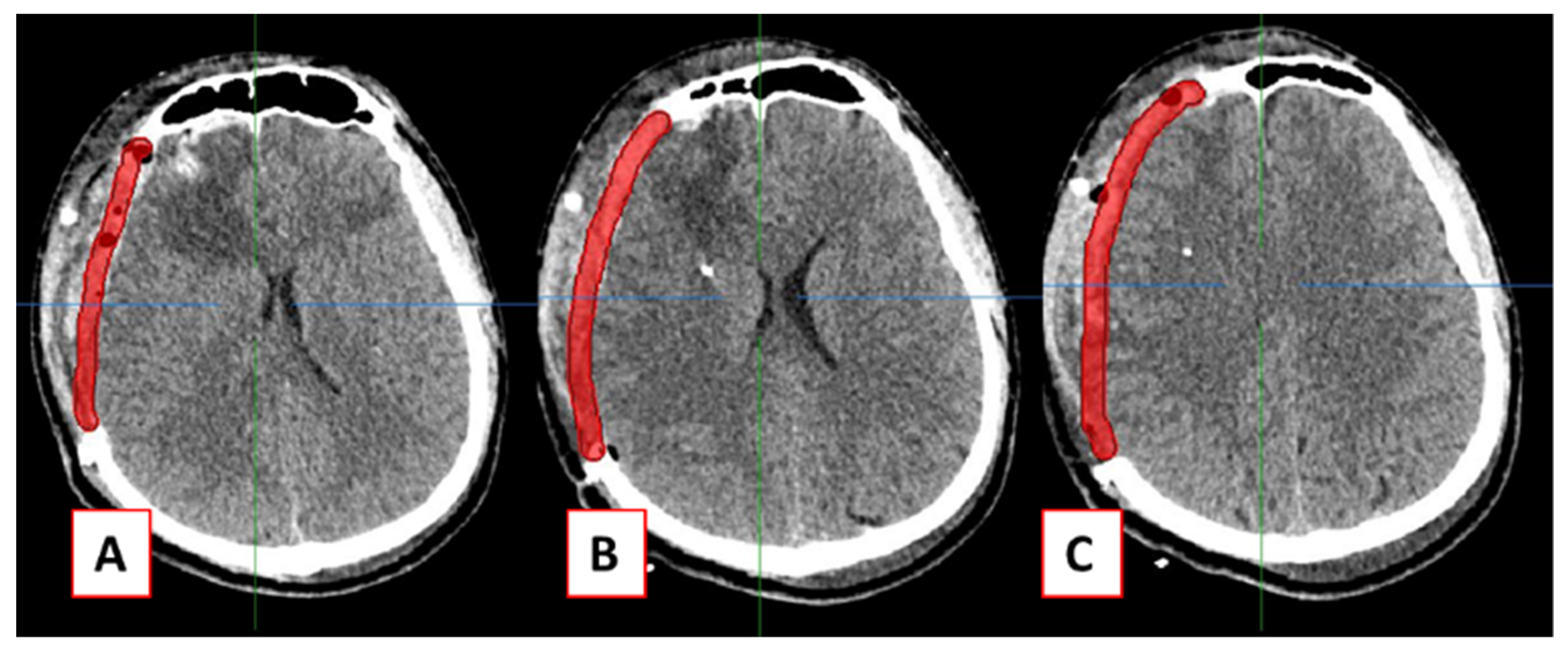
Figure 5.
Green circles indicated unreconstructed surfaces due to under-interpolation.

Figure 6.
The final cranial implant before editing (left) and after editing (right).
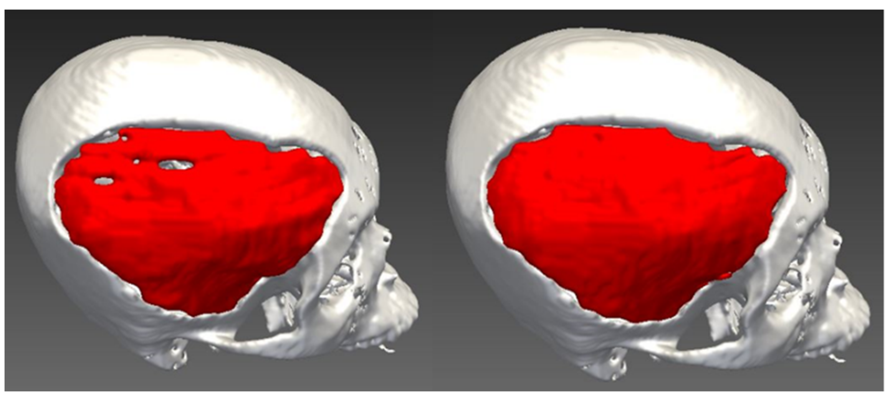
Figure 7.
Lines drawn on every tenth axial slice (left) and every fifth slice (right) on the coronal slice of CT data.
Figure 7.
Lines drawn on every tenth axial slice (left) and every fifth slice (right) on the coronal slice of CT data.
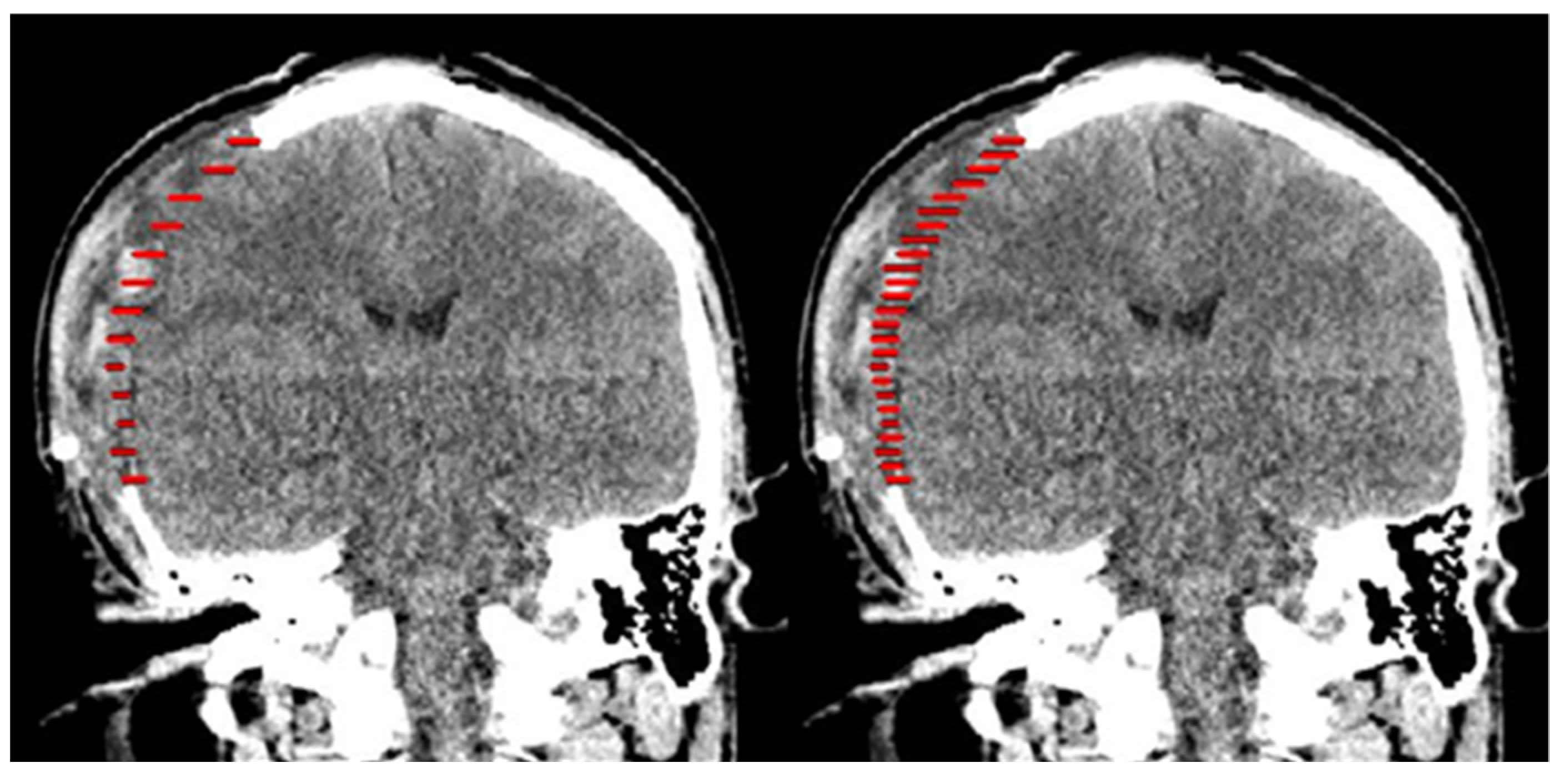
Figure 8.
The patient-specific cranial implant with every tenth slice interpolation (left) and every fifth slice interpolation (right).
Figure 8.
The patient-specific cranial implant with every tenth slice interpolation (left) and every fifth slice interpolation (right).

Figure 9.
HD for two superimposed patient-specific cranial implants computed using CloudCompare software.
Figure 9.
HD for two superimposed patient-specific cranial implants computed using CloudCompare software.


Table 1.
The cranial implant surface and volume for three different methods.
| Variable | n | * Cranial Implant Surface (mm2) | ** Cranial Implant Volume (mm3) |
|---|---|---|---|
| Median (IQR) | Median (IQR) | ||
| 3-matic | 10 | 26211.8 (2944.9) | 68823.9 (21778.4) |
| MITK: 10th slice | 10 | 22616.0 (6614.0) | 57242.3 (27463.4) |
| MITH: 5th slice | 10 | 24102.9 (8351.3) | 68655.1 (23758.5) |
* p = 0.389 and ** p = 0.468 using Kruskal–Wallis Test.
Table 2.
Geometric analyses (HD) of cranial implants.
| Cranial Implant | 3-Matic vs. MITK Tenth Slice | 3-Matic vs. MITK Fifth Slice |
|---|---|---|
| 1 | 0.456 | 0.355 |
| 2 | 0.423 | 0.271 |
| 3 | 0.148 | 0.097 |
| 4 | 0.480 | 0.342 |
| 5 | 0.106 | 0.002 |
| 6 | 0.333 | 0.145 |
| 7 | 0.425 | 0.260 |
| 8 | 0.116 | 0.016 |
| 9 | 0.020 | 0.024 |
| 10 | 0.301 | 0.017 |
| Mean (SD) | 0.281 (0.17) | 0.152 (0.14) |
All HD values are in mm.
Table 3.
Geometric analyses (DSC) of cranial implants.
| Cranial Implant | 3-Matic vs. MITK Tenth Slice | 3-Matic vs. MITK Fifth Slice |
|---|---|---|
| 1 | 0.856 | 0.888 |
| 2 | 0.776 | 0.891 |
| 3 | 0.879 | 0.894 |
| 4 | 0.788 | 0.825 |
| 5 | 0.898 | 0.922 |
| 6 | 0.884 | 0.907 |
| 7 | 0.882 | 0.912 |
| 8 | 0.794 | 0.871 |
| 9 | 0.916 | 0.931 |
| 10 | 0.837 | 0.925 |
| Mean (SD) | 0.851 (0.05) | 0.897 (0.03) |
DSC values ranges from 0 (no overlap) to 1 (complete overlap).
Publisher’s Note: MDPI stays neutral with regard to jurisdictional claims in published maps and institutional affiliations. |
© 2021 by the authors. Licensee MDPI, Basel, Switzerland. This article is an open access article distributed under the terms and conditions of the Creative Commons Attribution (CC BY) license (https://creativecommons.org/licenses/by/4.0/).
Share and Cite
MDPI and ACS Style
Abdullah, J.Y.; Abdullah, A.M.; Hueh, L.P.; Husein, A.; Hadi, H.; Rajion, Z.A. Cranial Implant Design Applying Shape-Based Interpolation Method via Open-Source Software. Appl. Sci. 2021, 11, 7604. https://doi.org/10.3390/app11167604
AMA Style
Abdullah JY, Abdullah AM, Hueh LP, Husein A, Hadi H, Rajion ZA. Cranial Implant Design Applying Shape-Based Interpolation Method via Open-Source Software. Applied Sciences. 2021; 11(16):7604. https://doi.org/10.3390/app11167604
Chicago/Turabian StyleAbdullah, Johari Yap, Abdul Manaf Abdullah, Low Peh Hueh, Adam Husein, Helmi Hadi, and Zainul Ahmad Rajion. 2021. "Cranial Implant Design Applying Shape-Based Interpolation Method via Open-Source Software" Applied Sciences 11, no. 16: 7604. https://doi.org/10.3390/app11167604
Note that from the first issue of 2016, this journal uses article numbers instead of page numbers. See further details here.