Article

Study on Microstructure, Mechanical Properties and Erosion Characteristics of Al-Si Alloy Manufactured by Continuous Casting Direct Rolling Process

Department of Materials Science and Engineering, National Cheng Kung University, Tainan 701, Taiwan
*
Author to whom correspondence should be addressed.
Appl. Sci. 2021, 11(18), 8351; https://doi.org/10.3390/app11188351
Submission received: 10 August 2021 / Revised: 3 September 2021 / Accepted: 6 September 2021 / Published: 9 September 2021
(This article belongs to the Topic Metallurgical and Materials Engineering)

Abstract

:
Al-Si alloys exhibit promising wear resistance, thus being mainly employed to weld Al alloy parts and processed into components of equipment. During the new continuous casting direct rolling (CCDR) process, the raw material gradually cools and solidifies, simultaneously plastically deformed. Hence, the materials manufactured through the CCDR process presented an unparalleled microstructure. The experimental results indicated that the strength of the CCDR Al-Si alloy can be increased through cold rolling. A two-stage heat treatment (solid solution and aging treatment) was introduced to improve the ductility and satisfy the industrial application. Furthermore, the erosion wear characteristics and fracture mechanism of the CCDR Al-Si alloy dominated by the ductility were confirmed. Both cold rolling specimens (FR) and those with heat treatment (FRH) showed greater wear resistance than as-manufactured (F). The FR specimens exhibited greater wear resistance owing to a higher Al matrix strength at a lower impact angle; on the other hand, at a higher impact angle, the FRH specimens with a softer Al matrix presented better wear resistance due to the formation of a lip structure to reduce material removal. The TEM results confirmed that the nanoscale grains formation was induced in the erosion-affected region and affected the Si concentration. Conclusively, the heat-treated CCDR Al-Si alloy possessed excellent erosion resistance and workability, which can serve as a reference processed as wear-resistant mechanical parts.

1. Introduction

The continuous casting direct rolling (CCDR) process comprises continuous casting and hot-strip rolling [1,2,3,4]. The CCDR process significantly features deformations that can be accomplished on the same production line. As for energy efficiency and costs caused by the labor and process, the CCDR process is regarded as a promising high-efficiency production technology in industrial applications. Compared with the traditional casting and extrusion processes, the CCDR process contributes to high-strength quenched microstructure formations exhibiting excellent mechanical properties [4,5]. The materials applied in the CCDR process are mainly copper and iron-based alloys [2,6].
Now, only steel and copper alloys have CCDR products; the aluminum alloy has a low melting point, a narrow solidification temperature range, and insufficient material strength, so there is no CCDR product. It is worth noting that CCDR technology for Al alloys has gradually aroused attention in recent years, but current reports on Al-Si alloys are still rare [3,5,7,8]. Therefore, the Al-Si alloy, considered as highly fluid and with excellent wear resistance, was introduced to the CCDR process for the purpose of developing high wear-resistant materials used in the industry [3,9,10].
In previous literature, Si efficiently increased the fluidity of the Al alloy as a liquid state, inhibited its thermal expansion rate, and formed a Si solid solution in the Al matrix to improve the wear resistance [11,12,13,14,15]. The aforementioned properties contribute to this alloy wildly employed as a welding material for Al alloy parts and as a cylinder head or a lifter between the piston in engine systems [16]. According to the advantages reported in previous studies, combining the CCDR process with a potential Al-Si alloy can further improve the mechanical properties and considerably save production costs [3,5].
Considering the cold workability of wire rods used in the production of a Al-Si alloy for high wear-resistant purposes, the rolling process was added after the CCDR process to compare the mechanical properties and wear resistance [17]. Nevertheless, cold rolling will also be accompanied by the disadvantage of a reduced ductility. The cold-worked wire bars would increase the ductility after the two-stage heat treatment for industrial applications [18,19,20]. In addition, reducing the residual stress and improving the ductility after cold working through recrystallization was contributed by the two-stage heat treatment, including a solid solution treatment and aging treatment [21]. The specimens after cold rolling were subjected to the solid solution treatment at 540 °C for 4 h (water quench) and aging at 170 °C for 12 h (air cooling) [22,23]. The solid solubility of Si in Al is rare under 523 K in the Al-Si phase diagram, and Si precipitation would redissolve into the Al matrix after the solid solution treatment beyond this temperature [24].
Several studies have reported that the ceramic particles hit the metal specimens’ surface at a high speed during particle erosion, and kinetic energy is transformed into heat, which can raise the temperature of the surface to 400–500 °C instantaneously [25,26,27]. This phenomenon of high temperature and local high stress effects the results in the phase transform (phase dissolved or formation) on the surface and has been demonstrated on other metal materials [26,28,29,30]. The phase transform plays an important role, affecting the hardness and mechanical properties [29,31,32]. Therefore, the investigation of the phase transform mechanism and examination reliability after particle erosion in the CCDR Al-Si alloy subjected to different conditions is the main concept in this study. Compared with traditional processes, where the Al alloys are first cast, demolded, and cut into billets and then subjected to hot extrusion or rolling to form bars or plates of specific sizes, the CCDR process effectively reduces the production costs [2,3]. The results of this study can serve as a major breakthrough in the industrial application research of the CCDR Al-Si alloy. Relevant literature worldwide on the CCDR Al-Si alloy is currently still lacking, so the results provide a crucial reference for Al alloy processing technology.

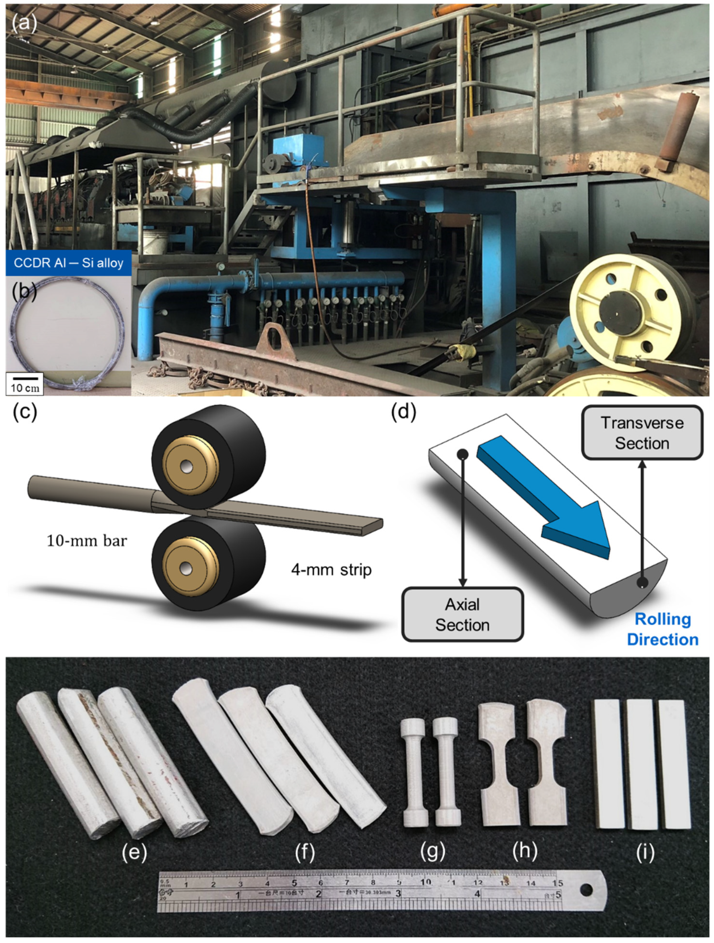
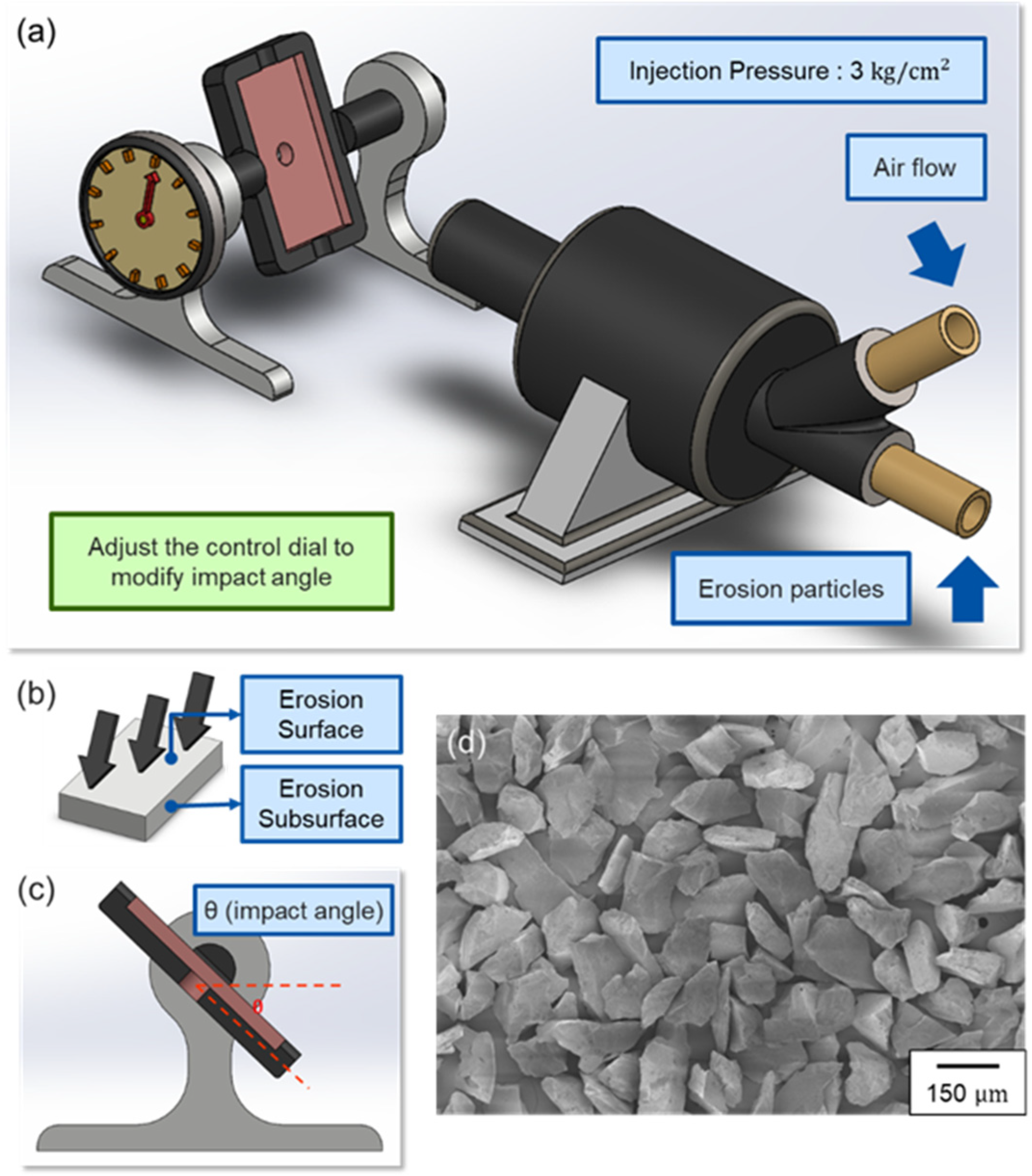
2. Materials and Methods

In the CCDR process, a single machine directly produces Al alloy wire coils (Figure 1a,b), Tainan, Taiwan, Ting Sin Co., Ltd.. In this study, CCDR Al-Si alloy bars with diameters ϕ10 mm serve as the research materials applied in the tensile and erosion wear tests, shown in Figure 1e–i (as-manufactured and under processing). The chemical compositions of the research materials named “F” are as shown in Table 1. In the pre-experiment, CCDR Al-Si alloy bars were rolled into strips of different thicknesses through different reduction rates, then used to confirm the maximum cold working limit of cold rolling by the observation of crack formations on the edges of specimens. As the results exhibited, the reduction ratio was set at 60%, which was named “FR” (diameter of the specimen: 10 mm→4 mm), as shown in Figure 1c. Moreover, FR were subjected to solid solution treatment at 540 °C for 4 h (water quench) and aging at 170 °C for 12 h (air cooling). Those were named “FRH”. The parameters and motivations are summarized in Table 2.
The microstructure was observed in the parallel (axial section) and vertical (transverse section) directions to the rolling direction from the CCDR process, as shown in Figure 1d with an optical microscope (Olympus BX41M-LED, Tokyo, Japan) and scanning electron microscopy (SEM) (Hitachi SU-5000, Hitachi, Tokyo, Japan). The specimens were grounded with #80–#4000 SiC sandpaper and polished with 1 and 0.3-μm Al2O3 and 0.05-μm SiO2 powder. Afterwards, Keller’s reagent (19-mL HNO3 + 9-mL HCl + 6-mL HF + 19-mL H2O) was used to etch the surface.
For the tensile test, the F was processed into dumbbell-shaped tensile specimens (Figure 2a). After the rolling process, the bars were transformed into sheets, the FR and FRH were processed into dog-bone-shaped tensile specimens (Figure 2b) at a fixed tensile rate of 1 mm/ min. Each parameter was subjected to ten times tensile tests for averaging the strength and elongation. The hardness was detected in units of HRF (Mitutoyo AR-10, Kawasaki, Japan).
The erosion specimens and experimental equipment to investigate the wear resistance are shown in Figure 3a–c. The eroded particles (Figure 3d) are irregular Al2O3 particles (range from 125 to 150 μm). The erosion test was conducted with 200-g Al2O3 ceramic particles, the inlet pressure was fixed at 3 kgf cm 2 , and the working distance was 20 cm. The impact angle ranged from 15° to 90°, and the interval increment was 15°. Each condition was tested with five specimens. The erosion rate is defined by the total mass of the removed material divided by that of the eroded particles hitting the surface, showing the erosion rate changing at different angles [25,26].
The phase of as-manufactured (F) was analyzed with cold rolling (FR) and the two-stage heat treatment after cold rolling (FRH) of the CCDR Al-Si alloy, as well as the phase transformation induced by particle erosion wear on the specimen surface. The F, FR, and FRH groups were named the FE, FRE, and FRHE groups, respectively, after the erosion wear. An X-ray diffractometer (Bruker AXS GmbH, Karlsruhe, Germany) detected the phase structure of the surfaces of all the specimens to clarify the particle erosion mechanism. Moreover, to further investigate the surface crystal structure and fine grains caused by erosion-induced phase transformation, the focused ion beam (FEI Helios G3CX, Houston, TX, USA) cutting a cross-section of FRH with the best wear resistance under a high angle was surveyed by transmission electron microscopy (TEM) (JEOL JEM-2100F, Tokyo, Japan) [25,26,33].

3. Results and Discussion

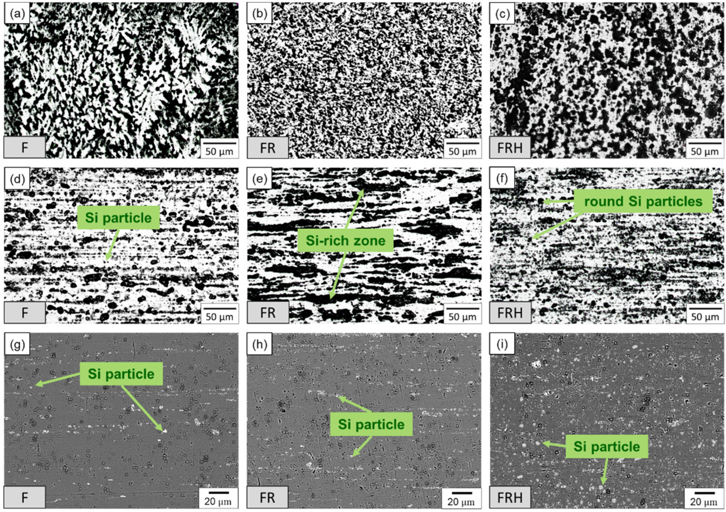
3.1. Microstructural Characteristics

Figure 4 presents the microstructures of the F, FR, and FRH in the axial and transverse sections. The white and dark regions indicate that the Al matrix and Si precipitations, respectively. A comparison of Figure 4a,d reveals that the materials manufactured through the CCDR process (F) exhibited microstructural differences in different sections. The dendritic structure was partially destroyed and the irregular Si organization aggregated in the transverse section after the cold rolling process in the FR specimen, as shown in Figure 4b,e. However, an inconspicuous change in microstructure of the axial section can be observed through OM. In contrast to the F specimen, FR showed a long strip of Si-rich zone transform into a thicker one caused by stress compression. The FRH specimen shown in Figure 4c,f. Si precipitation was crushed during cold rolling and redissolved into the Al matrix by the solid solution treatment, resulting in round Si particles and an oval-shaped Si-rich zone formation after the aging treatment. An observation by the Si particles through backscattered electronic (BSE) image in microstructure of the axial section is shown in Figure 4g–i.
The size and distribution of the Si particle influences on the Al matrix play a significant role in the mechanical strength and ductility of Al-Si alloys [34]. Different shapes of Si particles in the microstructure can be changed by F, FR, and FRH. Refining the Si particle can substantially improve the material ductility to satisfy the requirements for industrial application [28].

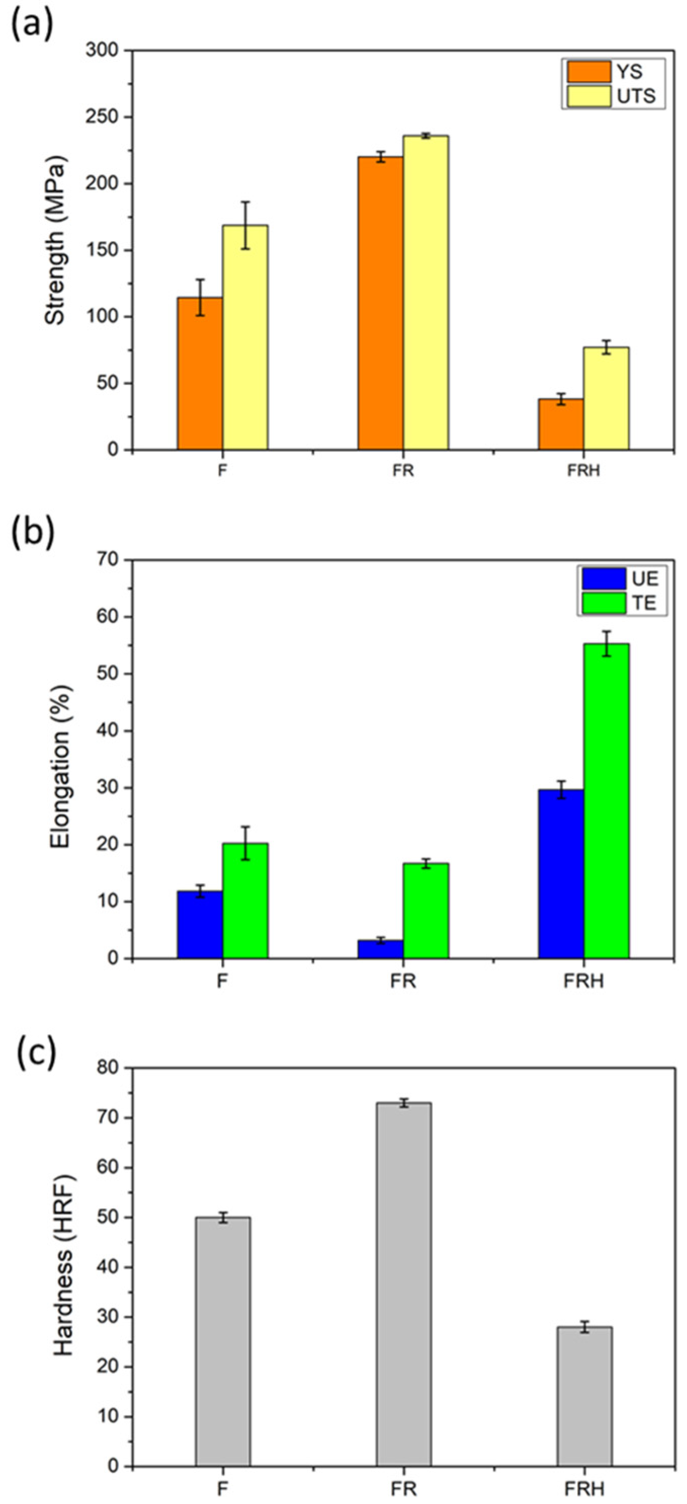
3.2. Tensile Mechanical Properties and Hardness

Figure 5a, after cold rolling, the yield strength (YS) of the specimens increased from 115 to 220 MPa, and the ultimate tensile strength (UTS) increased from 169 MPa to 240 MPa. Figure 5b exhibited the uniform elongation (UE) and total elongation (TE), which decreased from 11.8% and 20.2% to 3.2% and 16.7% after cold rolling, respectively. Compared to the literature [34], the CCDR Al-Si alloy displayed mechanical properties superior to that of the traditional processes. The aforementioned ductility cannot satisfy further cold workings to form fasteners, thinner wires, and screws; therefore, the heat treatment is necessary for ductile improvement.
As shown in Figure 5a, after the heat treatment, (FR→FRH), both YS and UTS were reduced (Table 3). Figure 5b indicated that the ductility was significantly improved in both the UE and TE after the heat treatment (Table 3). The ductility can correspond to the industrial need; on the other hand, the strength dramatically decreased. Conclusively, there are two main reasons for the substantial increase in ductility: (1) the dendritic structure partial fracture recrystallized and equiaxed after the heat treatment, and (2) the Si particles become finer, round, and blunt after the heat treatment, which can alleviate the tensile crack propagation rate [28,35,36].
The hardness (Figure 5c) indicated that cold rolling can increase the HRF hardness to approximately 70 and decrease it to approximately 30 after the heat treatment. Since the Si content exceeded the solid solubility in the Al matrix, the solid solution strengthening effect achieved the limit and was difficult to increase by the heat treatment. Although the rounding of the Si particles caused a decrease in the hardness, the heat treatment reduced the brittleness effect for better workability of the CCRD Al-Si alloy. Nevertheless, for the purpose of CCDR Al-Si alloy manufacturing, we should consider not only mechanical properties but, also, the wear resistance [3,37].

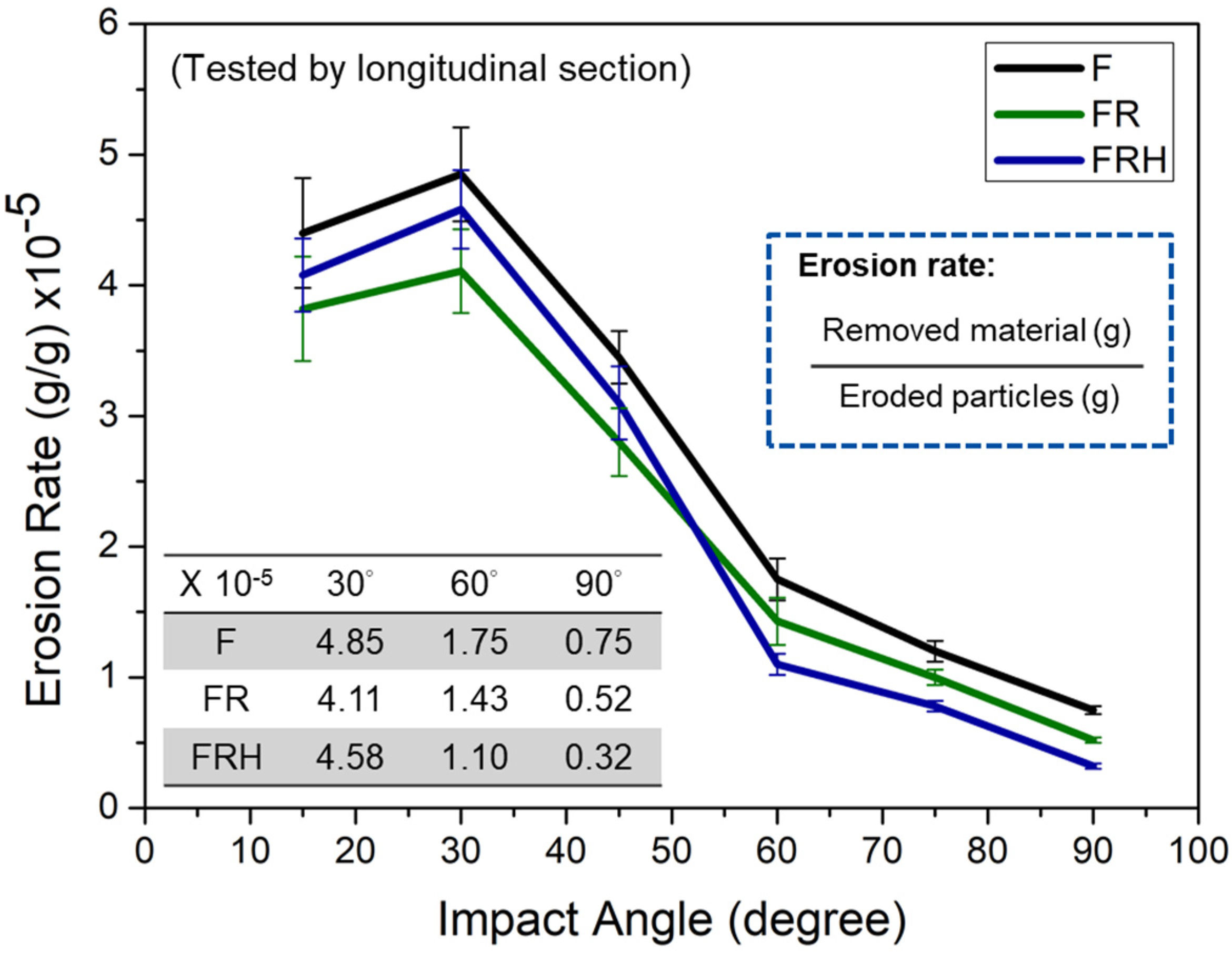
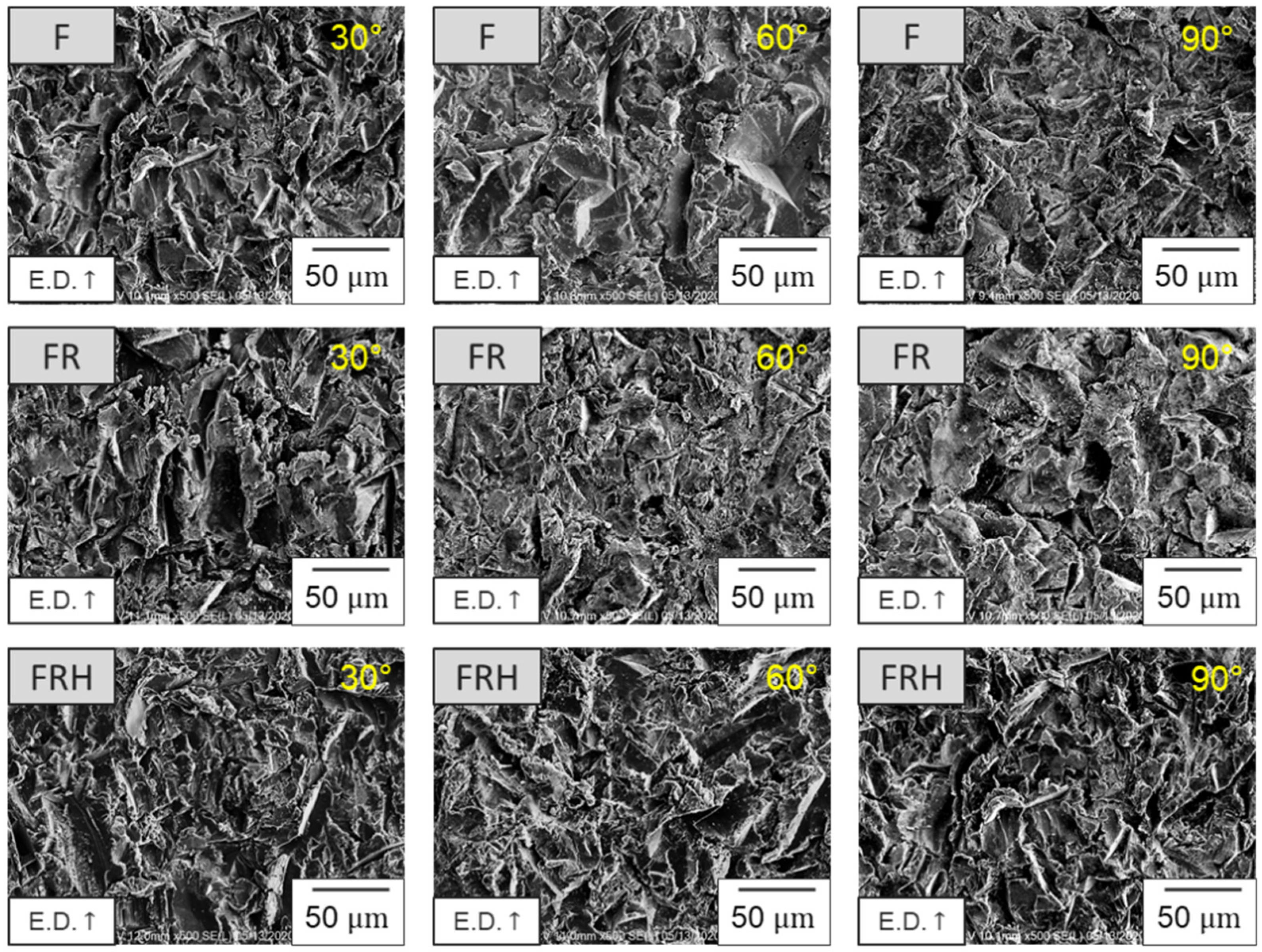
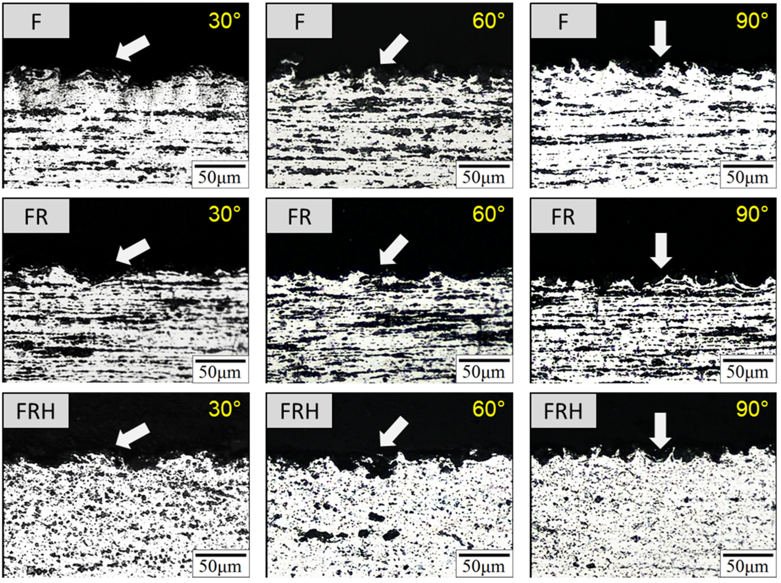
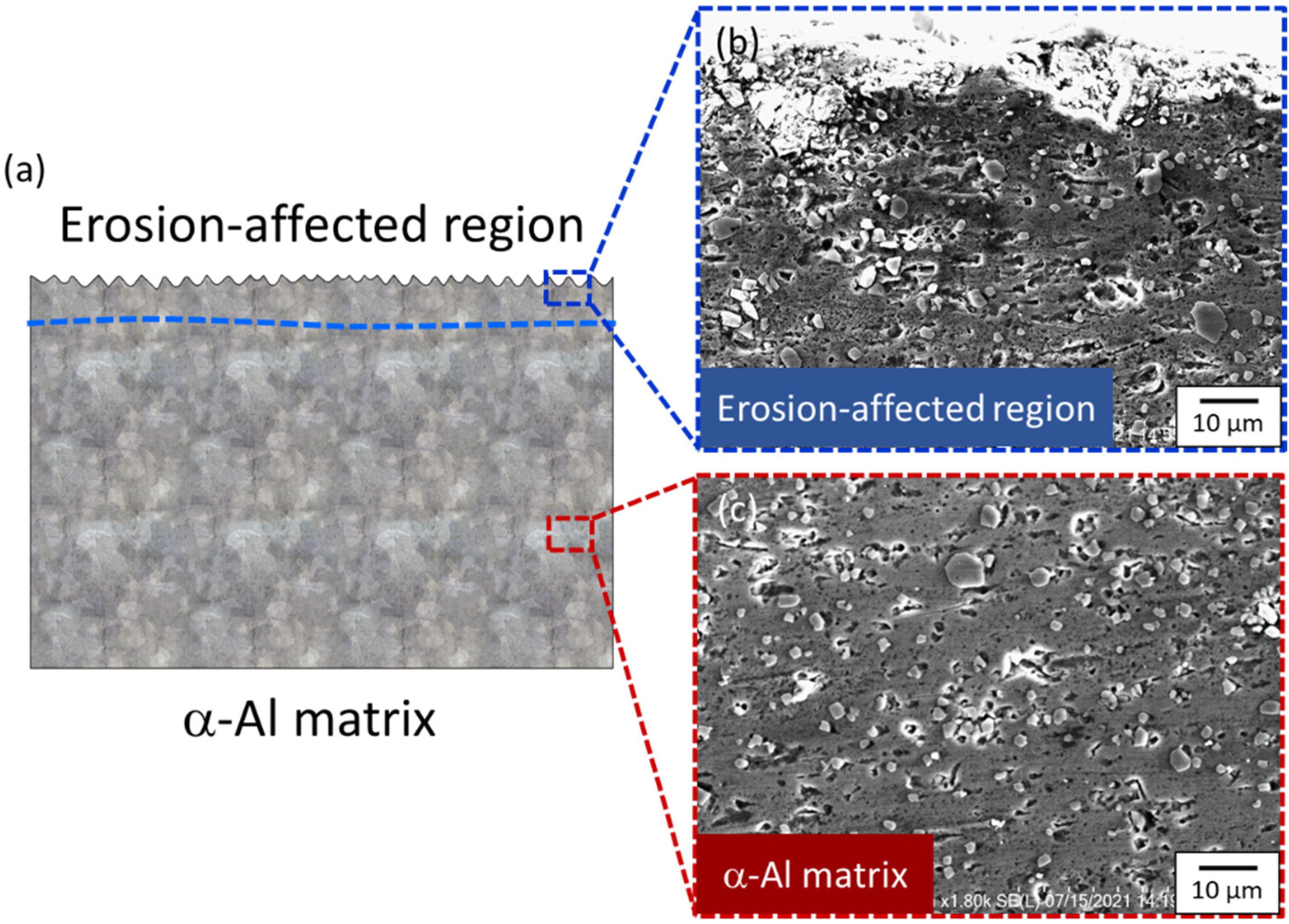
3.3. Characteristics and Mechanism of Erosion

Figure 6 exhibited the erosion rates at different impact angles. The maximum erosion rate represented the lowest wear resistance, and the impact angle corresponding to the maximum erosion rate revealed the dominance of the wear mechanism.
According to previous studies, the typically ductility wear mechanism is collectively controlled by cutting, plowing, and plastic deformation. In the range of 15–30°, as the angle increases, the corresponding erosion rate gradually increases; in contrast, the erosion rate gradually decreases in the range of 30–90° [38,39]. The results conducted on the three specimens indicated a typical ductile fracture mode, with the maximum erosion rate located at an impact angle of 30° and the minimum erosion rate observed at 90°. The erosion rates of the specimens were ranked as F > FR > FRH as an impact angle lower than 45° and F > FRH > FR as an impact angle greater than 45°. Notably, under all the impact angle conditions, the F specimen exhibited the lowest wear resistance.
Under low-impact angle conditions, the high hardness brought out the FR specimens’ greater wear resistance; on the other hand, under high-impact angle conditions, the FRH specimens with the lowest hardness showed higher wear resistance. It can be concluded that the effect of hardness on the erosion wear resistance depended on the conditions at different impact angles. On the other hand, compared with the erosion results of the traditional Al-Si alloy, the CCRD Al-Si alloy has better wear resistance [26].

3.4. Surface Characteristics of Erosion

Figure 7 and Figure 8 present the morphology of the surface and subsurface at impact angles of 30°, 60°, and 90°, respectively. At angle 30°, all the specimens exhibited clear grooves on the erosion surface due to the particle impact. Compared with F and FRH, the FR specimen exhibited a narrower groove width characteristic, which can indicate that a high hardness leads to a high wear resistance and forms a shallower groove trend in FR [27,29]. On the contrary, the FRH specimen with the softest matrix cannot afford a particle impact and demonstrates the cutting phenomenon, with an appearance like a squeezed lip on the erosion surface [40,41,42].
At an impact angle of 90°, the erosion rate was ordered as F > FR > FRH, with Al2O3 particles vertically impacted on the specimen surface. Due to its high hardness but low ductility, the FR specimen revealed a fractured morphology, as of brittle materials, with amounts of crack growth by high-speed impact from Al2O3 particles. Nevertheless, the FRH with high ductility yields a substantial buffering effect to counteract the plastic deformation after erosion, appearing as plenty of grooves on the erosion surface. The F specimen showed characteristics between FR and FRH. [43,44].

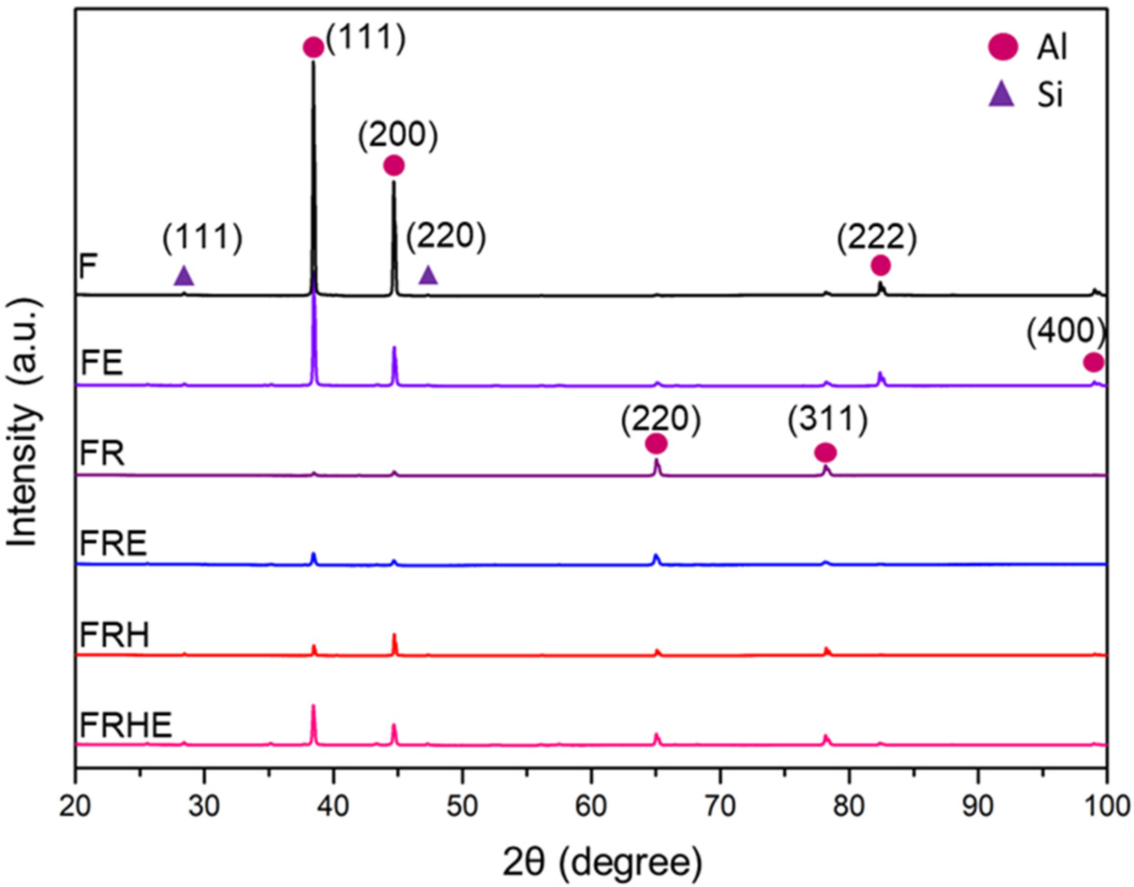
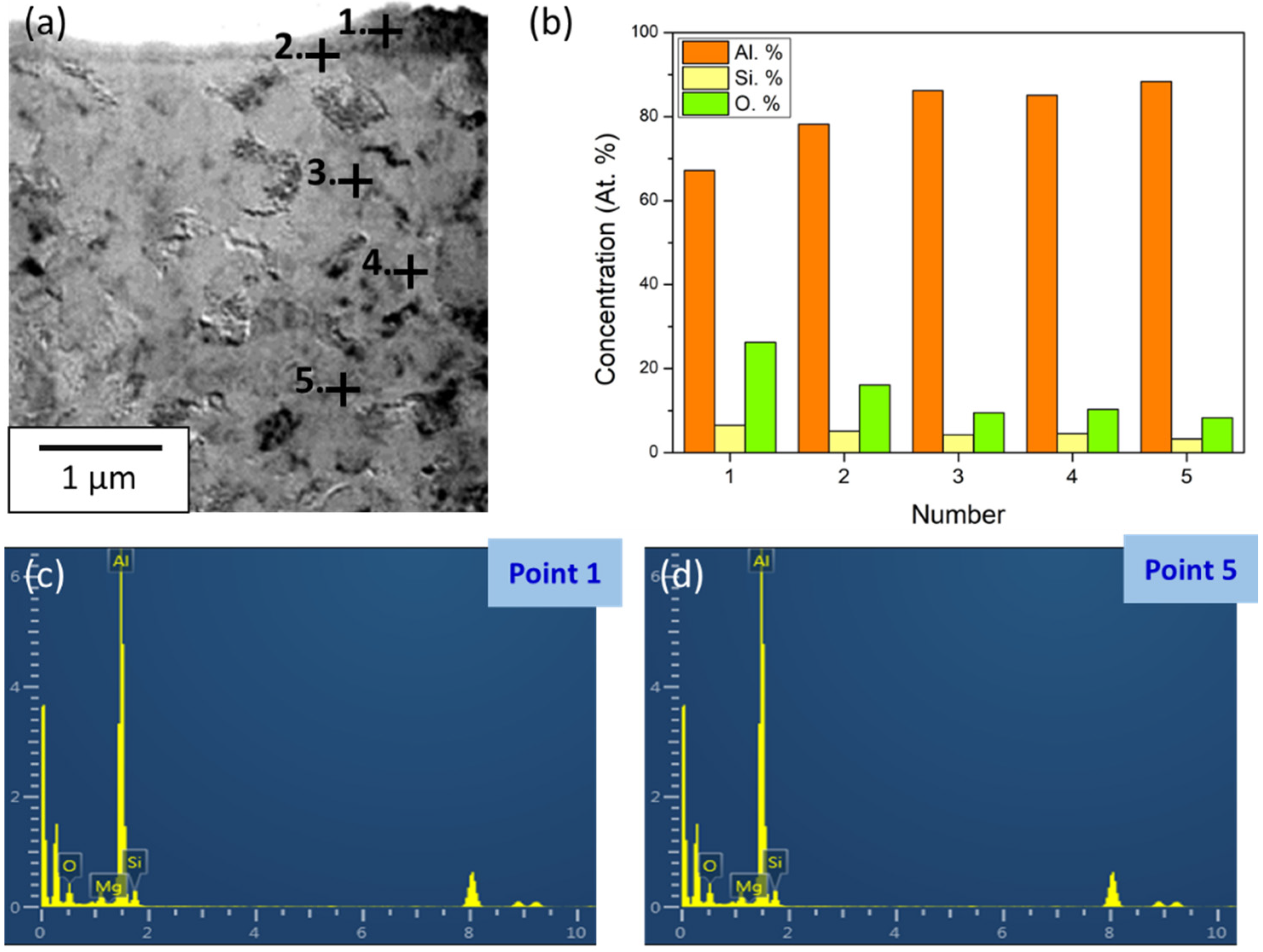
3.5. Surface Phase Composition after Erosion

According to the literature, the particle erosion prompt surface temperature up to 400–500 °C contributed to phase transformation [25,27]. After erosion, the Si particles in the Al-Si alloys dissolved the solids into the Al matrix [24,45,46].
The specimens subjected to the erosion wear experiment were named FE, FRE, and FRHE, respectively. The surface phase before and after erosion wear were investigated through XRD (Figure 9). The results indicated that the peaks strength all changed slightly after erosion, with no other peaks emerging. The reason why the peak intensities are changed is affected by the breaking of the dendrites and solid solution of the primary crystal Si, while slightly altering the preferred orientation [29,47]. In general, the alter-orientation resulted in the peak intensities decreasing and broadening. The high temperature induced by erosion caused recrystallization and grain refining to occur, which is another factor that causes broadening peaks. However, because the depth of the erosion-affected region was several μm, it caused material removal due to erosion. Therefore, the phenomenon of the broadening of peaks cannot be observed.
The material texture orientation transformation after cold rolling resulted in the peak intensities substantially decreasing, and the texture effect further altered after the heat treatment. What is worth noting is that the FRHE specimen exhibited conspicuous texture orientation of the Al matrix compared to that of FRH. This study applied TEM to confirm the changes in the texture effect. In addition, the application data of the CCDR Al-Si alloy was summarized in Table 4.

3.6. Erosion Induces Phase Transformation

To further clarify the phase transformation before and after erosion, the FRH with the highest wear resistance under 90° was surveyed by SEM and TEM. The erosion subsurface was divided into two regions, consisting of an erosion-affected region on the top and α-Al matrix below (Figure 10). In the former region, the high temperature during erosion induced Si nanoprecipitation. The compositions of the Al, Si, and O depth changes in the Al matrix were detected by the EDS of TEM (Figure 11a–d). The results revealed two parts: (1) Si gradually decreasing while away from the erosion surface and the (2) O concentration increasing in the erosion-affected region, indicating Al oxidization to Al2O3.
In Figure 12a, the nanoscale grains were comprised of the erosion-affected region, at a depth of approximately 0.4 um, with a clear boundary segmentation of the erosion-affected region and α-Al matrix. In mapping the results of the EDS, Si was solid-dissolved in both regions (Figure 12b) compared to the EDS results in Figure 12b, which revealed that Si has a low solubility in the α-Al matrix. Therefore, the Si solution diffraction pattern could not be observed in Figure 12e.
The bright field and SAED patterns of the α-Al matrix and erosion-affected region are shown in Figure 12c–f. The sampling positions of Figure 12e,f are, respectively, marked by the circles in Figure 12c,d. Al lattice distortion is caused by a solid solution of Si and Figure 12e. The phase transformation schematic is exhibited in Figure 13. The erosion-affected region was composed of fine grains by erosion; the SAED pattern presented the diffraction consisting of multiple crystal planes (Figure 12f). Compared with α-Al grains in the matrix, extremely fine grains can serve as a resistance effect to protect the particle impact and difficultly forming such pits after erosion. These results not only corresponded with FRH coming as the highest erosion rate at high angles but also reflected the grain orientation changing in the XRD results.

4. Conclusions

  • The strength of the CCDR Al-Si alloy can be significantly improved through cold rolling; ductility is not suitable for further processing. The two-stage heat treatment increase the ductility but decreases the strength, in comparison to the former, though it can satisfy the requirements for secondary cold working.
  • The CCDR Al-Si alloy under different conditions exhibited a ductile-dominated erosion mechanism. Cold rolling alone or in combination with a heat treatment both improved the wear resistance. The FR specimen showed the best wear resistance at a lower angle, but the FRH specimen was at a higher impact angle.
  • The CCDR Al-Si alloy had a stable phase structure; no new phase appeared, and both the peak intensity and preferred orientation changed after erosion wear. Erosion induced fine grains, and a Si solid solution effect improved the erosion resistance.

Author Contributions

Methodology, B.-C.H.; investigation, B.-C.H.; data curation, B.-C.H.; writing—original draft preparation, B.-C.H.; writing—review and editing, K.-C.C. and F.-Y.H.; and supervision, F.-Y.H. All authors have read and agreed to the published version of the manuscript.

Funding

This research received no external funding.

Institutional Review Board Statement

Not applicable.

Informed Consent Statement

Not applicable.

Data Availability Statement

The data presented in this study are available on request from the corresponding author. The data are not publicly available due to privacy or ethics.

Acknowledgments

The authors are grateful to Taiwan TING SIN Co., Ltd. and the Ministry of Science and Technology of Taiwan (Grant No. MOST 108-2221-E-006-140-MY3) for their financial support. The authors appreciate the Ting Sin Co., Ltd. for providing the CCDR Al-Si alloy bars as the research materials.

Conflicts of Interest

The authors declare no conflict of interest.

References

  1. Kase, M.; Matsuzuka, K.; Takahashi, H.; Oba, H.; Hirata, O. Continuous casting direct rolling technology at Nippon Steel’s Sakai Works. Steel Times 1985, 213, 268. [Google Scholar]
  2. Echigo, R.; Yoshida, H.; Mochizuki, T. Temperature Equalization by the Radiative Converter for a Slab in Continuous Casting Direct Rolling. JSME Int. J. Ser. 2 Fluids Eng. Heat Transf. Power Combust. Thermophys. Prop. 1988, 31, 545–552. [Google Scholar] [CrossRef] [Green Version]
  3. Zhao, J.-R.; Hung, F.-Y.; Chen, B.-J. Effects of heat treatment on a novel continuous casting direct rolling 6056 aluminum alloy: Cold rolling characteristics and tensile fracture properties. J. Mater. Res. Technol. 2021, 11, 535–547. [Google Scholar] [CrossRef]
  4. Muntin, A.V. Advanced Technology of Combined Thin Slab Continuous Casting and Steel Strip Hot Rolling. Metallurgist 2019, 62, 900–910. [Google Scholar] [CrossRef]
  5. Amiri, M.M.; Fereshteh-Saniee, F. An Experimental Investigation on the Effect of Cooling Rate During Combined Continuous Casting and Rolling Process on Mechanical Properties of 7075 Aluminum Alloy. Trans. Indian Inst. Met. 2019, 73, 441–448. [Google Scholar] [CrossRef]
  6. Maehara, Y.; Nakai, K.; Yasumoto, K.; Mishima, T. Hot Cracking of Low Alloy Steels in Simulated Continuous Casting-Direct Rolling Process. Trans. Iron Steel Inst. Jpn. 1988, 28, 1021–1027. [Google Scholar] [CrossRef]
  7. Kim, M.G.; Lee, G.C.; Park, J.P. Materials Science Forum; Trans Tech Publications Ltd.: Kapellweg, Switzerland, 2010; Volume 638, pp. 255–260. [Google Scholar]
  8. Zhang, X.Y.; Zhang, H.; Kong, X.X.; Fu, D.F. Microstructure and properties of Al–0.70 Fe–0.24 Cu alloy conductor prepared by horizontal continuous casting and subsequent continuous extrusion forming. Trans. Nonferrous Met. Soc. China 2015, 25, 1763–1769. [Google Scholar] [CrossRef]
  9. Hernandez, F.C.R.; Ramírez, J.M.H.; Mackay, R. Al-Si Alloys: Automotive, Aeronautical, and Aerospace Applications; Springer: Berlin/Heidelberg, Germany, 2017. [Google Scholar]
  10. Casalegno, V.; Salvo, M.; Rizzo, S.; Goglio, L.; Damiano, O.; Ferraris, M. Joining of carbon fibre reinforced polymer to Al-Si alloy for space applications. Int. J. Adhes. Adhes. 2018, 82, 146–152. [Google Scholar] [CrossRef]
  11. Heusler, L.; Schneider, W. Influence of alloying elements on the thermal analysis results of Al-Si cast alloys. J. Light Met. 2002, 2, 17–26. [Google Scholar] [CrossRef]
  12. Yang, Y.; Yu, K.; Li, Y.; Zhao, D.; Liu, X. Evolution of nickel-rich phases in Al-Si-Cu-Ni-Mg piston alloys with different Cu additions. Mater. Des. 2012, 33, 220–225. [Google Scholar] [CrossRef]
  13. Ye, H. An Overview of the Development of Al-Si-Alloy Based Material for Engine Applications. J. Mater. Eng. Perform. 2003, 12, 288–297. [Google Scholar] [CrossRef]
  14. Dahle, A.K.; Tøndel, P.A.; Paradies, C.J.; Arnberg, L. Effect of grain refinement on the fluidity of two commercial Al-Si foundry alloys. Met. Mater. Trans. A 1996, 27, 2305–2313. [Google Scholar] [CrossRef]
  15. Ravi, K.; Pillai, R.; Amaranathan, K.; Pai, B.; Chakraborty, M. Fluidity of aluminum alloys and composites: A review. J. Alloy. Compd. 2008, 456, 201–210. [Google Scholar] [CrossRef]
  16. El-Gamal, S.; Mohammed, G. Effects of γ-irradiation and strain rate on the tensile and the electrical properties of Al-4043 alloy. Radiat. Phys. Chem. 2014, 99, 68–73. [Google Scholar] [CrossRef]
  17. Li, J.; Feng, Q.; Liu, F.; Wu, W. Experimental studies of the tooth wear resistance with different profiles in single screw compressor. Tribol. Int. 2013, 57, 210–215. [Google Scholar] [CrossRef]
  18. Stošic, N.; Milutinović, L.; Hanjalić, K.; Kovačević, A. Investigation of the influence of oil injection upon the screw compressor working process. Int. J. Refrig. 1992, 15, 206–220. [Google Scholar] [CrossRef]
  19. Fastykovskii, A.; Chinokalov, E.; Prudnikov, A.; Oskolkova, T. IOP Conference Series: Materials Science and Engineering; IOP Publishing: Novokuznetsk, Russia, 2020; Volume 866, p. 012016. [Google Scholar]
  20. Fastykovskii, A.R.; Chinokalov, E.V.; Milovanov, A.G.; Myskova, N.V.; Shumkin, A.A. Cold-Drawn Reinforcing Wire with Screw Profile. Metallurgist 2014, 58, 540–544. [Google Scholar] [CrossRef]
  21. Gupta, M.; Lavernia, E.J. Effect of processing on the microstructural variation and heat-treatment response of a hypercutectic Al-Si alloy. J. Mater. Process. Technol. 1995, 54, 261–270. [Google Scholar] [CrossRef]
  22. Xu, Z.; Zhao, Z.; Han, D.; Chen, Q.; Li, Z. Effects of Si Content and Aging Temperature on Wear Resistance of Surfacing Layers Welded with 4043 Aluminum Welding Wires. Rare Met. Mater. Eng. 2016, 45, 71–74. [Google Scholar]
  23. Singh, R.K.; Telang, A.; Das, S. Microstructure and mechanical properties of Al-Si alloy in as-cast and heat treated condition. Am. J. Eng. Res. 2016, 5, 133–137. [Google Scholar]
  24. El-Khalek, A.A.; El-Salam, F.A. Effect of irradiation and pre-ageing temperature on the mechanical properties of Al-Si alloy. Radiat. Eff. Defects Solids 2008, 163, 835–842. [Google Scholar] [CrossRef]
  25. Hung, F.-Y.; Chen, L.-H.; Lui, T.-S. Phase Transformation of an Austempered Ductile Iron during an Erosion Process. Mater. Trans. 2004, 45, 2981–2986. [Google Scholar] [CrossRef]
  26. Liou, J.; Lui, T.; Chen, L. SiO2 particle erosion of A356.2 aluminum alloy and the related microstructural changes. Wear 1997, 211, 169–176. [Google Scholar] [CrossRef]
  27. Zhao, J.-R.; Hung, F.-Y.; Lui, T.-S. Particle Erosion Induced Phase Transformation of Different Matrix Microstructures of Powder Bed Fusion Ti-6Al-4V Alloy Flakes. Metals 2019, 9, 730. [Google Scholar] [CrossRef] [Green Version]
  28. Chuang, H.C.; Lui, T.S.; Chen, L.H. Characteristics and Effects of Particle Morphology and Tensile Ductility Resulting from FSP of Al-Si-Cu-Ni Casting and Forging Piston. Mater. Trans. 2013, 54, 1373–1380. [Google Scholar] [CrossRef] [Green Version]
  29. Zhao, J.-R.; Hung, F.-Y.; Lui, T.-S. Erosion Resistance and Particle Erosion-Induced Tensile Embrittlement of 3D-Selective Laser Melting Inconel 718 Superalloy. Metals 2019, 10, 21. [Google Scholar] [CrossRef] [Green Version]
  30. Wood, R.; Walker, J.; Harvey, T.; Wang, S.; Rajahram, S. Influence of microstructure on the erosion and erosion–corrosion characteristics of 316 stainless steel. Wear 2013, 306, 254–262. [Google Scholar] [CrossRef]
  31. Chintapalli, R.K.; Marro, F.G.; Jimenez-Pique, E.; Anglada, M. Phase transformation and subsurface damage in 3Y-TZP after sandblasting. Dent. Mater. 2013, 29, 566–572. [Google Scholar] [CrossRef]
  32. Ye, Y.; Li, J.; Lv, X.; Liu, L. Study on Failure Mechanism and Phase Transformation of 304 Stainless Steel during Erosion Wear. Metals 2020, 10, 1427. [Google Scholar] [CrossRef]
  33. Chang, K.C.; Zhao, J.R.; Hung, F.Y. Effects of Hyper-High-Temperature Solid-Solution Treatment on Microstructure Evolution and Nanoprecipitation of the Al-Ni-Cu-Fe-Zr-Sc Alloy Manufactured by Selective Laser Melting. J. Alloy. Compd. 2021, 883, 160781. [Google Scholar] [CrossRef]
  34. Saad, G.; Fayek, S.; Fawzy, A.; Soliman, H.; Mohammed, G. Deformation characteristics of Al-4043 alloy. Mater. Sci. Eng. A 2010, 527, 904–910. [Google Scholar] [CrossRef]
  35. Farkoosh, A.; Javidani, M.; Hoseini, M.; Larouche, D.; Pekguleryuz, M. Phase formation in as-solidified and heat-treated Al-Si-Cu-Mg-Ni alloys: Thermodynamic assessment and experimental investigation for alloy design. J. Alloy. Compd. 2013, 551, 596–606. [Google Scholar] [CrossRef]
  36. Huang, B.C.; Hung, F.Y. Al2O3 Particle Erosion Induced Phase Transformation: Structure, Mechanical Property, and Impact Toughness of an SLM Al-10Si-Mg Alloy. Nanomaterials 2021, 11, 2131. [Google Scholar] [CrossRef]
  37. Chen, K.-J.; Hung, F.-Y.; Lui, T.-S.; Tsai, C.-L. Improving the applicability of wear-resistant Al–10Si–0.5 Mg alloy obtained through selective laser melting with T6 treatment in high-temperature, and high-wear environments. J. Mater. Res. Technol. 2020, 9, 9242–9252. [Google Scholar] [CrossRef]
  38. Hovis, S.; Talia, J.; Scattergood, R. Erosion mechanisms in aluminum and Al-Si alloys. Wear 1986, 107, 175–181. [Google Scholar] [CrossRef]
  39. Magnee, A. Generalized law of erosion: Application to various alloys and intermetallics. Wear 1995, 181, 500–510. [Google Scholar] [CrossRef]
  40. Daoud, A.; El-Khair, M.T.A.; Abdel-Azim, A.N. Effect of Al2O3 Particles on the Microstructure and Sliding Wear of 7075 Al Alloy Manufactured by Squeeze Casting Method. J. Mater. Eng. Perform. 2004, 13, 135–143. [Google Scholar] [CrossRef]
  41. Das, S.; Mondal, D.P.; Sawla, S. Solid particle erosion of Al alloy and Al-alloy composites: Effect of heat treatment and angle of impingement. Met. Mater. Trans. A 2004, 35, 1369–1379. [Google Scholar] [CrossRef]
  42. Stachowiak, G.; Batchelor, A.W. Engineering Tribology; Butterworth-Heinemann: Oxford, UK, 2013. [Google Scholar]
  43. Bellman, R.; Levy, A. Erosion mechanism in ductile metals. Wear 1981, 70, 1–27. [Google Scholar] [CrossRef] [Green Version]
  44. Sheldon, G.L. Effects of Surface Hardness and Other Material Properties on Erosive Wear of Metals by Solid Particles. J. Eng. Mater. Technol. 1977, 99, 133–137. [Google Scholar] [CrossRef]
  45. Das, S.; Mondal, D.; Sawla, S.; Ramakrishnan, N. Synergic effect of reinforcement and heat treatment on the two body abrasive wear of an Al-Si alloy under varying loads and abrasive sizes. Wear 2008, 264, 47–59. [Google Scholar] [CrossRef]
  46. Kasprzak, W.; Chen, L.D.; Shaha, S. Heat treatment development for a rapidly solidified heat resistant cast Al-Si alloy. J. Mater. Eng. Perform. 2013, 22, 1839–1847. [Google Scholar] [CrossRef]
  47. Cai, F.; Huang, X.; Yang, Q.; Nagy, D. Effect of Microstructure on the Solid Particle Erosion Properties of Ni Plating. J. Mater. Eng. Perform. 2009, 18, 305–311. [Google Scholar] [CrossRef]
Figure 1. (a) Al-Si alloy CCDR equipment, (b) bar coil of the CCDR Al-Si alloy, (c) schematic diagram of the bar being cold rolled into strip, (d) the definition of the axial and transverse sections, (e) as-manufactured and (f) as-manufactured after rolling, (g) dumbbell-shaped tensile specimens, (h) dog-bone-shaped tensile specimens, and (i) specimens for erosion wear.
Applsci 11 08351 g001
Figure 2. Specifications of the tensile specimens: (a) group F, (b) groups FR and FRH, and (c) specimens for erosion wear (a flow chart of three pieces combined into one piece).
Applsci 11 08351 g002
Figure 3. (a) The erosion test equipment developed by our group, (b) the position of the erosion surface (working surface) and the erosion subsurface, (c) the cross-sectional view of the specimen carrier and the definition of impact angle, and (d) Al2O3 ceramic particles for erosion wear experiments.
Applsci 11 08351 g003
Figure 4. The microstructure evolution of the CCDR Al–Si alloy after cold rolling and T6 heat treatment after cold rolling in the axial section and the transverse section: (a) F, transverse, (b) F, axial, (c) FR, transverse, (d) FR, axial, (e) FRH, transverse, and (f) FRH, axial. BSE image of (g) F, axial, (h) FR, axial, and (i) FRH F, axial.
Applsci 11 08351 g004
Figure 5. Tensile properties: (a) strength, (b) elongation, and (c) HRF hardness of the CCDR Al–Si alloy.
Applsci 11 08351 g005
Figure 6. Erosion rate as a function of the impact angle of the CCDR Al–Si alloy.
Applsci 11 08351 g006
Figure 7. The SEM morphology of the erosion surface.
Applsci 11 08351 g007
Figure 8. Microstructure characteristics of the subsurface of erosion (the arrow represents the direction of particle erosion).
Applsci 11 08351 g008
Figure 9. The XRD analysis of the erosion surface of each specimen before and after erosion.
Applsci 11 08351 g009
Figure 10. (a) The schematic diagram of the erosion-affected region and α-Al matrix, the SEM image of (b) the erosion-affected region, and the (c) α-Al matrix.
Applsci 11 08351 g010
Figure 11. (a) EDS sampling point, (b) changes of the element concentrations at different points, and the element pattern of (c) point 1 and (d) point 5.
Applsci 11 08351 g011
Figure 12. (a) TEM image of FIB cross-section view, (b) EDS elemental mapping images, TEM bright field image of (c) the α-Al matrix, (d) an erosion-affected region, corresponding to the SAED pattern of (e) the α-Al matrix, and (f) an erosion-affected region.
Applsci 11 08351 g012
Figure 13. The schematic diagram of the structural characteristics and morphology of the phase transformation mechanism.
Applsci 11 08351 g013
Table 1. Chemical composition analysis of the Al–Si alloy (wt.%).
ElementsAlSiFeCuMnMgZnTi
CompositionBal.4.860.230.0790.0030.0020.0170.02
Table 2. Treatment conditions and motivations for each group.
GroupTreatment ConditionsMotivations
FAs-manufacturedfundamental material properties evaluation
FRas-manufactured + rollingstrain hardening
FRHAs-manufactured + rolling + heat treatmentsecondary cold working
Table 3. Mechanical properties of the Al–Si alloy.
GroupYS (MPa)UTS (MPa)UE (%)TE (%)HRF
F11516911.820.250
FR2202403.216.773
FRH387729.755.328
SD of YS (MPa)SD of UTS (MPa)SD of UE (%)SD of TE (%)SD of HRF
F13.6017.641.072.881.00
FR3.871.750.530.800.80
FRH4.124.971.522.161.10
Table 4. Comparison of the material application properties (●: better).
Continuous ProductionSave Energy, and Process CostsWorkabilityErosion Wear ResistanceStable Phase Structure
CCDR process
Traditional Process
Publisher’s Note: MDPI stays neutral with regard to jurisdictional claims in published maps and institutional affiliations.

