
Design and Experimental Analyses of Hybrid Piston Rods Used in Hydraulic Cylinders under Axial Load


School of Mechanical and Aerospace Engineering, Gyeongsang National University, Jinju-si 52828, Korea
*
Author to whom correspondence should be addressed.
Appl. Sci. 2021, 11(18), 8552; https://doi.org/10.3390/app11188552
Submission received: 29 July 2021
/
Revised: 5 September 2021
/
Accepted: 8 September 2021
/
Published: 15 September 2021
(This article belongs to the Topic Metallurgical and Materials Engineering)
Abstract
:Composite hydraulic cylinders are used to reduce the weight of construction equipment such as aerial work platforms or excavators. The weight is compensated by manufacturing hydraulic cylinders from Carbon Fiber Reinsforced Plastic (CFRP), but this is expensive. Therefore, this study investigated a hybrid hydraulic cylinder, which is a combination of CFRP and steel, considering both performance and cost. The conventional hydraulic cylinder rods are made of steel, which can prevent failure due to buckling under push load (Push) or failure under alternating push–pull load (Push–Pull) or pull only. In this paper, we discuss how the failure threshold for these two mechanisms can be increased by making the piston rod from a hybrid material. In order to develop this lightweight hybrid piston rod for hydraulic cylinders that meets the buckling strength requirements of the original steel rod, CFRP is used as a substitute, which has significant buckling strength against compressive loading and, most importantly, is lighter than steel. The substitution is done either by replacing steel completely with CFRP or by reducing the volume of steel and sheathing it with CFRP. Numerical and experimental studies are carried out to understand the strength and behavior of piston rods when they are replaced by different combinations of composite materials for the given load. For this study, two different piston rod designs with various design parameters were considered, and their respective behavior under loading was discussed. The effect of compressive loads on CFRP wrapped steel parts and buckling strength as a function of fiber orientation, stacking angle and number of CFRP layers was investigated using experiments. The study demonstrated the usefulness of steel-CFRP composites to reduce weight and their influence on buckling load in hydraulic cylinders.
1. Introduction
In recent years, the weight of construction and heavy industrial machinery is considered a problem, as it contributes to higher fuel consumption and thus more emissions and environmental damage. Various methods are being considered to reduce weight. There is a continuous and progressive process of weight reduction in structural components. This weight reduction in structural components not only reduces fuel consumption but also increases the performance of the machine due to reduction in inertial forces. The objective of this study is to replace conventional steel hydraulic cylinder rods with cylinder rods made of a combination of steel and CFRP to reduce the weight of the piston rod without compromising its structural strength. This lightweight piston rod is to be used in a hydraulic cylinder, which in turn reduces the weight of the hydraulic cylinder. If the weight of the hydraulic cylinder is reduced by 1 kg, the weight of the construction machine can be reduced by up to 6 kg, that is, we can reduce the weight of the construction machine up to six times by reducing the weight of a single cylinder. This is because a single machine uses more than 6 to 8 hydraulic cylinders which vary in size and function [1].
In a hydraulic cylinder, the piston rod (as shown in Figure 1) is the heaviest component and accounts for about 40% of the total weight of the cylinder. The piston rod is usually made of solid steel which is capable of withstanding the buckling load. Buckling is a sudden, large and unstable deflection in the lateral direction that occurs at a critical value when the compressive load increases slightly. This buckling in the piston rod of a hydraulic cylinder is caused by the combination of hydrostatic pressure and external forces that reduce the load carrying capacity of the piston rod. When the piston rod buckles, it collapses and can be bent (see Figure 2), causing serious accidents and malfunctions. Therefore, buckling resistance is a major hazard for the piston rod, which must be protected against such failures, and designers must take precautions against such failures in the design and development of hydraulic cylinders [2,3].
Our plan is to either replace the piston rod with another material or minimize the use of steel in piston rods without compromising their load carrying capacity, i.e., their buckling strength. In recent years, almost all heavy industries have realized the importance of weight reduction and started looking for lightweight materials. Most industries started switching from steel to other high-grade metals like titanium, magnesium, etc., which are highly resistant to corrosion from acid attacks and external environmental conditions. They also have lower density than steel but are much more expensive than steel. Figure 3 below shows how the cost varies with the weight of the materials [4].
With the introduction of polymers in the mid-1960s, most industries turned their attention to these materials for their purposes. This is due to the fact that polymers are very strong yet lightweight material. It is two times stiffer and five times stronger than steel and significantly lighter than steel. These combined properties make it an ideal manufacturing material that is preferred by engineers and designers in manufacturing. These polymers are naturally anisotropic, which means their strength and properties are directional, making them even more superior as they can carry the load in their stronger direction. Their properties are mainly influenced by the choice of fibers used, the orientation of the fibers, type of resin and the curing conditions. Depending on the application, different techniques are used to produce them, namely, hand lay-up, resin transfer molding, infusion, pultrusion, filament winding, autoclave, etc.
The filament winding technique (see Figure 4) is more advantageous for high pressure pipe applications and also provides excellent design flexibility as the winding angle can be varied by adjusting the number of turns, resulting in exceptional strength in the tensile direction. For this reason, several research works have been carried out to favor the use of CFRP in the automotive industry. Since buckling failure is due to the high influence of load in one direction, the use of CFRP for the bar is the right choice as a substitute material for steel as they are lightweight, high strength and cheaper than conventional metals. However, due to the complexity in assembly and machinability of composites, their applications are mainly limited to complex geometries. Therefore, we planned to combine this CFRP material with machined steel to increase the strength and compensate the strength loss of steel due to the reduction of its original volume for lightweight applications. More studies focus on the buckling failure phenomenon either only for steel or only for CFRP, and only a few have been carried out for the combination of steel and CFRP.
Solazzi demonstrated the possibility of using composite materials in hydraulic cylinders by completely replacing the steel with CFRP and reducing the weight by 10.5% [6,7]. There are not many studies that focus on the buckling resistance of steel linings in composite with CFRP. Our work focuses on understanding the influence of CFRP when it is wrapped on a steel liner and subjected to compressive loading in the axial direction. Due to the axial loading, we chose to use unidirectional carbon fibers in combination with steel and conducted a series of experiments to understand their behavior under high compressive loads. The design and strength of piston rods in hydraulic cylinders are studied using numerical and experimental results [8,9,10].
2. Materials and Methods
2.1. Analysis Method
The buckling resistance of the piston rod is the most important parameter in hydraulic cylinders. There are three types of failure when hydraulic rods are subjected to compressive loading, either crushing, buckling or both. Generally, the hydraulic rod with shorter length fails by crushing, while the longer rod fails by buckling, and the intermediate stages usually fail by both (see Table 1) [11]. The shortness and length of rod are classified based on slenderness ratio, which is the ratio between the effective length of rod and the smallest gyration radius.
Buckling failure in longer rods is mainly due to the stiffness of material and geometry and is independent of material strength. The failure usually occurs within the elastic range of the material. Euler’s theory is usually used to predict the buckling load of rods in hydraulic cylinders. It is based on the assumption that a structure is initially straight and the compressive load is applied axially at the center of gravity of the structure [12]. The critical buckling load of a structure is determined by the following equation
where Pcr is the critical buckling load, E is the elastic modulus of the material, I is the moment of inertia resisting the buckling direction, K is the effective length factor that depends on type of support the structure is under during loading, and is the length of the structure.
However, yielding considerations cannot be completely ignored since the rod will suffer deflection (due to the above imperfections) that will increase with load, leading to a bending moment that will cause failure before the critical Euler load is reached. It can be assumed that the actual failure is due to bending stress rather than buckling. For any value of slenderness ratio less than 120 (Le/K < 120), the error is too large for the application of Euler’s theory. Therefore, Rankine–Gordon extended Euler’s theory to include the crushing load generated in short columns [13,14]. The stress that leads to buckling according to Euler’s formula for a fixed–fixed condition is
Euler’s stress,
since I = AK2, then
where
then
This value is compared with yield strength of material to check if yielding occurs before buckling in a structure.
where is the crushing stress; then,
where
Then,
In Figure 5 the slenderness ratio is plotted against the buckling stress (σe) and is shown in the curve ABC. The actual value at failure should be below and within line CBD considering all imperfections that occur during loading and in the structure [15].
In our study, we used both Euler’s equation and Rankine–Gordon equation as a function of piston rod length to calculate and experimentally verify the buckling load of the steel as results are tabulated in Table 4. Using the calculated results, the buckling load for CFRP material was also predicted by subtracting the value of the steel buckling load from the experimental results of the hybrid rod (steel + CFRP).
2.2. Experimental Method
A series of experiments were conducted to determine the buckling load of the proposed hybrid rod and to understand its failure phenomenon, using a Universal Testing machine. Schematic diagram of the test setup was depicted in Figure 6. The 647 Hydraulic Wedge Grip series machine (Testing Machine) was specifically designed for buckling tests and features versatile, easy-load wedge grips that allow specimens to be clamped in the same manner each time, which is desirable for repeatable test results. These adjustable wedge grips with symmetrical housing design ensure uniform specimen loading across the entire surface of the wedge. Once the specimen grips are activated, lateral movement does not change the clamping position. This fixture prevents bending stresses and slippage during testing, which can lead to unstable or invalid test results. Care has also been taken to ensure that specimens are not damaged and that no backlash occurs during testing. The vertical load is applied along the axial axis of the specimen at the end of the wedge grips using a servo-controlled hydraulic cylinder as shown in Figure 7. The lower end was fixed, and the wedge clamp end moved downward at a displacement of 10 mm/min in the axial direction. The testing machine was stopped immediately when the buckling load dropped drastically from previous load step. The testing machine has a capacity of 500 kN axial compression. Standard laboratory conditions of 20 ± 5 °C temperature and 65 ± 10% humidity were maintained according to ASTM E2954-15 standard, and care was also taken to protect the specimens from sunlight or local heating [16,17,18,19,20]. Figure 8 and Figure 9 show the failure modes of steel rods and hybrid rods after testing.
2.3. Test Samples
To determine the buckling strength of the rod, 16 specimens were prepared. They were categorized as Solid type hybrid rod and hollow type hybrid rod depending on the percentage of CFRP material combined with steel to form a single rod. For each category, there were 2 specimens for testing. The length of each rod was 650 mm and outer diameter was 30 mm. For hollow rod, the inner diameter was fixed at 10 mm. AISI 1045 steel and unidirectional CFRP were used for the analysis. Rust or primer on the steel surface was removed by sandblasting, and the surface was cleaned with Ace-Tone. To improve the adhesion between steel and CFRP, the surface of the bars was knurled. A special toughened epoxy urethane adhesive (DP6310NS) was used between steel and CFRP to ensure sufficient strength. This adhesive is readily available at our local market and also showed better strength compared to other adhesives available in the market. These specimens are loaded axially in the machine using wedge grips. The upper end of the specimen is loaded along the wedge and load is applied at this end. A specially adapted fixture has been used to fix the specimen at the lower end. A guard is provided to protect the tester from accidents during the test. The buckling load on the specimen is significantly affected by the axial stress distribution that develops during the test. All discrepancies are carefully removed before the test begins. Mechanical properties of steel and CFRP are depicted in below Table 2 and Table 3, respectively.
2.4. Numerical Analysis and Results
Finite element analyzes of the solid steel and hollow steel rod were performed to investigate their buckling behavior under axial loading and calibrate the numeric results to determine the appropriate outside diameter of steel rod to be wrapped with CFRP. ABAQUS/STANDARD (LANCZOS method) was used to obtain numerical results. The actual dimensions of the steel specimens used in experimental analysis were used to design the numerical model. A hexahedral element with 8 nodes (C3D8R) with reduced integration in ABAQUS was used to mesh the numerical model. A deformable homogeneous volume element was chosen to build the numerical model. Totally, 46,027 hexahedral elements were generated to solve each case. In such a case, Abaqus composes boundary conditions that couple the displacement and rotation of each shell node to the average displacement and rotation of the solid surface. The boundary conditions are applied such that the nodes at the bottom of the specimen are constrained to displacement and rotation in all degrees of freedom. At the top of the specimen, rotation is fixed in all directions, and translation is free only in the axial direction of the model (i.e., loading direction). The axial load of 98,066 N is applied in the vertical direction, and the numerical model is solved for 3 eigenmodes using the LANCZOS eigen solver as shown in Figure 9 and Figure 10 [20,21,22,23,24].
Numerical analysis was carried out for different diameters of solid and hollow steel rod, and results are tabulated in Table 4. Any bar whose outside and inside diameters could not withstand this minimum buckling load of 1 kN was neglected, and thus, the minimum outside diameter was determined to be 7.5 mm for solid steel rod and 15 mm for hybrid rods. The inner diameter for hollow steel rods was determined to be 10 mm.
3. Results and Discussion
3.1. Experimental Results
The influence of CFRP parameters such as the CFRP volume, the number of laminate plies and the laminate orientation on the buckling load of the hybrid solid and the hybrid hollow rod are shown in Table 5.
3.2. Solid Rod
3.2.1. Buckling Load against Laminates in Solid Hybrid Rod
Figure 11 shows the change in buckling load for the solid rod in a hydraulic cylinder application as a function of the number of laminate layers used in the CFRP. For both cases 1 and 2 of the solid rod, four specimens with a composite of steel and CFRP or CFRP only, the number of laminate layers was varied between 14 and 60. The buckling load decreased by 4% in case 1 when the number of laminates was increased from 14 to 30. However, for case 2, the decrease in buckling load over the same period is only 0.4% (negligible change), which means that the buckling load remains almost same even when the number of plies is increased. Further down, when the number of laminates is increased from 30 to 46 in both case 1 and case 2, both show a different trend, i.e., for case 1 there is a gradual increase in buckling load up to 16%, while in case 2 there is a decrease in buckling load up to 12%. It is interesting to note that the difference between the buckling load values of case 1 and case 2 is much less. Steel loses buckling strength as its diameter (volume) decreases. However, the addition of CFRP volume compensates for the buckling strength lost by steel without increasing the weight of the piston rod. When the number of laminate layers is further increased in both case 1 and case 2, the rates of change of buckling load are 4% and 7%, respectively, and the difference of buckling load values between the two cases slightly increases. This shows that the buckling load is not greatly affected when a smaller number of laminates are combined with steel (i.e., up to 50% of the total laminates), but when the number of laminate layers laid is higher, the buckling load is greatly affected. These results could be useful in optimizing the buckling load and weight of the piston rod in a hydraulic cylinder application. As shown, the variation in buckling load is minimal at higher values of CFRP volume fraction, and as the CFRP volume fraction increases, the weight of the cylinder decreases. These observed differences in buckling load carrying capacity of CFRP wrapped solid bars could be due to the key parameters of CFRP, such as fiber angle and orientation, which affect the buckling strength of the rod and need to be carefully selected in the design of the hybrid (steel + CFRP) rod.
3.2.2. Buckling Load versus 0° Ply in a Solid Hybrid Bar
Figure 12 shows the variation of buckling load against the number of 0° ply laminate used in CFRP of the solid rod in a hydraulic cylinder. During buckling, 0° ply laminates (fiber direction) are subjected to maximum loading for better results. It is important to have a greater number of plies along the loading direction to prevent the solid rod from bucking. Thus, 0° ply laminate are more in number compared to other ply angles. From the figure, it can be seen that for case 1, the buckling load inclines to maximum when the number of 0° ply laminate reaches 30, and then, it gradually declines. For case 2, it is maximum when the 0° ply laminate is lower (4), and it is a flat line when the number of 0° ply is increased, and on further increase in number, the buckling load drops which later increases with increase in number. It also means that when the number of 0° ply laminate is more than 50% in total laminate, it has a lower buckling load (e.g., case 1: 8 out of 14 laminates were 0° ply laminate).
The experimental results show a better buckling load when the number of 0° laminates is less than 40% (see table). This could be due to the fact that bending stress develops when the fibers in 0-ply laminate experience buckling failure, which is limited in other orientations of the laminate. The figure also shows that the intersections of case 1 and case 2 are at 2 points (i.e., when number of 0° ply laminates is between 27 and 34).
3.2.3. Buckling Load against 45° Laminates in a Solid Hybrid Rod
Figure 13 shows the change in buckling load as a function of the percentage of 45° laminate in CFRP of a solid rod in a hydraulic cylinder. The percentage of 45° laminate was selected in range between 5 and 30 percent of total laminate. From Figure 14, it can be seen that the buckling load increases as the percentage of 45° laminate increases. Compared to the two cases, case 2 has higher buckling load with higher percentage of 45° laminate. From Figure 10, it can be seen that the range of 45° laminate should be between 20 and 30% of the total ply laminate. However, there is a decrease in buckling load when the percentage of 45° laminate is increased from 20, but later, it increases with the increase in the percentage. This decrease could be due to the unbalanced selection of the other ply laminates along with the 45° laminate. The −45° laminate also shows a similar trend to the 45° laminate.
3.2.4. Buckling Load against 90° Ply Laminates in Solid CFRP
Figure 14 shows the change in buckling load as a function of the percentage of 90° plies in the CFRP of the solid rod in hydraulic cylinder. For both case 1 and case 2, the percentage of 90° ply laminates used was varied between 6% and 15%. It can be seen that both cases show a different trend in buckling load even with the same percentage. This shows that the percentage of 90 ply laminate has an effect on buckling load which depends only on the orientation and number of other plies used. It has no direct influence on the buckling load of the hybrid solid rod in the hydraulic cylinder.
3.3. Hollow Rod
3.3.1. Buckling Load VS. Laminates in a Hollow Hybrid Rod
Figure 15 shows that the number of laminates in the CFRP of the hollow rod does not have much effect on the buckling load, i.e., whether the number of laminate layers is higher or lower, the buckling load remains almost the same, and the curve remains flat. However, with the same number of CFRP laminates, the hollow rod in case 2 has a higher buckling load value than the hollow rod in case 1. This difference in values could be due to the orientation of the laminates and the distribution between each orientation. As mentioned earlier, the change in buckling load is less at higher volume of CFRP, which also means that the weight of the rod is greatly reduced at higher CFRP volume, and its buckling load capacity can be optimized by choosing the appropriate laminate angle, number and orientation.
3.3.2. Buckling Load against 0° Laminates in a Hollow Hybrid Rod
Figure 16 shows that the lower the percentage of 0° ply laminates in CFRP, the lower the buckling load of the hollow rod. In case 1, more than 50% of the CFRP laminate consists of 0° ply laminate, which results in a lower buckling load. As the number of 0° ply laminates increases, i.e., the percentage of 0° ply laminates in CFRP, the buckling load capacity of the hollow rod decreases. In case 2, the buckling load capacity of hollow rod increases with the increase of the percentage of 0° ply laminates in CFRP when it is less than 50% of the total laminate. However, when it is more than 50% of the total laminate, the buckling load decreases as the percentage of 0° ply laminate increases. This shows that it is best to choose 0° ply laminates with a proportion of less than 50% of the total laminates to achieve a higher buckling load.
3.3.3. Buckling Load versus 45° Laminates in a Hollow Hybrid Rod
Figure 17 shows that the buckling load of the hollow rod increases as the proportion of 45° plies in the CFRP laminate increases. There was a gradual increase in buckling load when the percentage of 45° ply laminates was increased from 10 to 15 (as in case 1), but there was a spike in the buckling load capacity of the hollow rod when the percentage of 45° ply laminates was increased from 20% to 28% (for case 2). This could be due to the fact that the 45° laminate suppresses the bending moment that occurs during buckling of the CFRP. The −45° laminate also shows a similar trend to the 45° laminate.
3.3.4. Buckling Load against 90° Ply Laminates in Hollow Hybrid Rod
Figure 18 shows the change in buckling load as a function of the percentage of 90° ply in the laminate. For both case 1 and case 2, the number of 90° ply laminates is increased from 2 to 4, i.e., from 10% to 15%. It can be seen that the buckling load increases slightly when the percentage of 90° laminates increases up to 13%, and when the percentage of 90° laminates is further increased, buckling load increases in case 1 while it decreases in case 2. This is due to the effects of different ply orientation and number of laminates. Thus, 90° laminate has no greater effect on the buckling load than other laminates.
4. Summary and Conclusions
This paper is concerned with the experimental investigation of the buckling strength of piston rods in hydraulic cylinders subjected to high compressive loads and made of steel and composite materials. First, a finite element analysis using ABAQUS/standard (LANCZOS method) was performed to determine the bending stress induced by the buckling load in a steel rod with different diameters. Experimental analysis was carried out on hybrid bars with different volume of CFRP and steel at constant length. The following was found:
- The buckling load is significantly affected by the percentage of CFRP volume in the hybrid bar, regardless of whether it is a solid or hollow bar. The higher the CFRP volume, the better the buckling load carrying capacity of the hybrid rods.
- The influence of the number of laminate layers on the buckling load depends largely on the angle and orientation of the laminates. They show better strength when the number of laminates is between 30 and 50.
- For axial load, 0° laminate layers bear the largest load compared to other laminate layers, so their number should be larger compared to other laminate layers. However, their volume should not exceed 50% of the total laminate layers. If their volume is more than 50%, the load carrying capacity of the hybrid bar will decrease. The best range is between 25% and 35% for higher buckling loads.
- The buckling load carrying capacity of the hybrid rod increases as the volume of the 45° laminate increases, and a range of 10% to 20% is recommended for best results. This range could be due to the fact that 45° laminate layers resist the bending induced by 0° laminate layers during axial loading, which further increases the buckling load capacity of the hybrid rod.
- The influence of 90° laminate plies on the buckling load capacity of the hybrid rod is much smaller and almost negligible.
It can be assumed that the buckling load carrying capacity of the hybrid bar is significantly affected by the change of CFRP volume fraction, number of laminate plies, fiber angle and fiber orientation.
This paper reports the main results of an investigation on the design and experimental testing of hybrid piston rods for hydraulic cylinders under axial load using steel and CFRP. The main research results aim to design and fabricate a lightweight hybrid rod that can withstand the maximum buckling load. Preliminary comparative analysis has been carried out for both solid and hollow steel rod with different volume of CFRP material. The steel composite piston rod used in hydraulic cylinders shows a weight reduction of up to 76% compared to a piston rod made of traditional mild steel. Research is therefore still ongoing, both in terms of structural and technological issues and of a comparative economic evaluation of the various solutions developed.
Author Contributions
Conceptualization, P.K.S.P.; methodology, P.K.S.P.; software, P.K.S.P.; validation, P.K.S.P. and S.-S.L.; formal analysis, P.K.S.P.; investigation, P.K.S.P.; resources, P.K.S.P. and S.-S.L.; data curation, P.K.S.P.; writing—original draft preparation, P.K.S.P.; writing—review and editing, P.K.S.P. and S.-S.L.; visualization, P.K.S.P.; supervision, S.-S.L.; project administration, P.K.S.P. All authors have read and agreed to the published version of the manuscript.
Funding
No funding acquired for this Project.
Institutional Review Board Statement
Not applicable.
Informed Consent Statement
Not applicable.
Data Availability Statement
Not applicable.
Acknowledgments
Not applicable.
Conflicts of Interest
The authors declare no conflict of interest.
References
- Njuguna, J. Lightweight Composite Structures in Transport Design, Manufacturing, Analysis and Performance; Woodhead Publishing Series in Composites Science and Engineering; Woodhead Publishing: Cambridge, MA, USA, 2016; Volume 67, p. 474. [Google Scholar]
- Omar, F.; Jim, T.; Mohini, S. Lightweight and Sustainable Materials for Automotive Applications; CRC Press: Boca Raton, FL, USA, 2017. [Google Scholar]
- Davies, J. Lightweight Sandwich Construction; CIB Working Commision: Manchester, UK, 2001; p. 369. [Google Scholar]
- Mallick, P. Materials, Design and Manufacturing for Lightweight Vehicles; CRC Press: Boca Raton, FL, USA, 2010. [Google Scholar]
- Brigante, D. New Composite Materials; Springer: Berlin/Heidelberg, Germany, 2014. [Google Scholar]
- Solazzi, L. Applied research for weight reduction of an industrial trailer. FME Trans. 2012, 40, 57–62. [Google Scholar]
- Solazzi, L. Wheel rims for industrial vehicles: Comparative and experimental analyses. Int. J. Heavy Veh. Syst. 2011, 18, 214–225. [Google Scholar] [CrossRef]
- Collotta, M.; Solazzi, L. New design concept of a tank made of plastic material for freighting vehicle. Int. J. Automot. Mech. Eng. 2017, 14, 4603–4615. [Google Scholar] [CrossRef]
- Solazzi, L.; Assi, A.; Ceresoli, F. New Design Concept for an Excavator Arms by Using Composite Material Applied Composite Materials. Appl. Compos. Mater. 2018, 25, 601–617. [Google Scholar] [CrossRef]
- Solazzi, L. Feasibility study of hydraulic cylinder subject to high pressure made of aluminum alloy and composite material. Compos. Struct. 2019, 209, 739–746. [Google Scholar] [CrossRef]
- Dump Cylinder-HY18-0032-Parker Hannifin. Available online: https://www.parker.com (accessed on 19 December 2018).
- Uzny, S.; Sokot, K.; Kutrowski, L. Stability of a hydraulic telescopic cylinder subjected to Euler’s load. In Proceedings of the 13th International Scientific Conference; Lecture Notes in Mechianical Engineering Series. Springer: Berlin/Heidelberg, Germany, 2017; Volume F10, pp. 581–588. [Google Scholar]
- Morelli, P. On the buckling behaviour of telescopic hydrasulic cylinders. Key Eng. Mater. 2010, 417–418, 281–284. [Google Scholar]
- Micheal, F. Ashby: Materials Selection in Mechanical Design, 3rd ed.; Butterworth-Heinemann: Oxford, UK, 2003. [Google Scholar]
- Agarwal, B.D.; Broutman, L.; Chandrashekhara, K. Analysis and Performace of Fiber Composites, 3rd ed.; Wiley: Hoboken, NJ, USA, 2006. [Google Scholar]
- Tiwari, A.; Alenezi, M.R.; Jun, S.C. Advanced Composite Materials; Scrivener Publishing LLC: Beverly, CA, USA, 2016. [Google Scholar]
- Balasuramanian, M. Composite Materials and Processing; CRC Press: Boca Raton, FL, USA, 2014. [Google Scholar]
- Kar, K. Composite Materials Processing, Applications, Characterizations; Springer: Berlin/Heidelberg, Germany, 2017. [Google Scholar]
- Schijve, J. Fatigue on Structures and Materials; Springer: Berlin/Heidelberg, Germany, 2009. [Google Scholar]
- Harris, B. Fatigue in Composites Science and Technology of the Fatigue Response of Fibre-Reinforced Plastics; Woodhead Publishing Limited; CRC Press: Boca Raton, FL, USA, 2003. [Google Scholar]
- Vassilopoulos, A. Fatigue Life Prediction of Composites and Composite Structures; Woodhead Publishing Limited; CRC Press: Boca Raton, FL, USA, 2010. [Google Scholar]
- Jones, R.M. Buckling of Bars, Plates and Shells; Bull Ridge Publishing: Blacksburg, VA, USA, 2006. [Google Scholar]
- Lin, R.; Guo, Y.; Lin, H. Critical load and optimum design for hydraulic cylinders. Zhongguo Jixie Gongcheng/China Mech. Eng. 2011, 22, 389–393. [Google Scholar]
- Vullo, V. Circular Cylinders and Pressure Vessel, Stress Analysis and Design; Springer: Berlin/Heidelberg, Germany, 2014. [Google Scholar]
Figure 1.
Hydraulic cylinder.

Figure 2.
Buckling failure pattern.
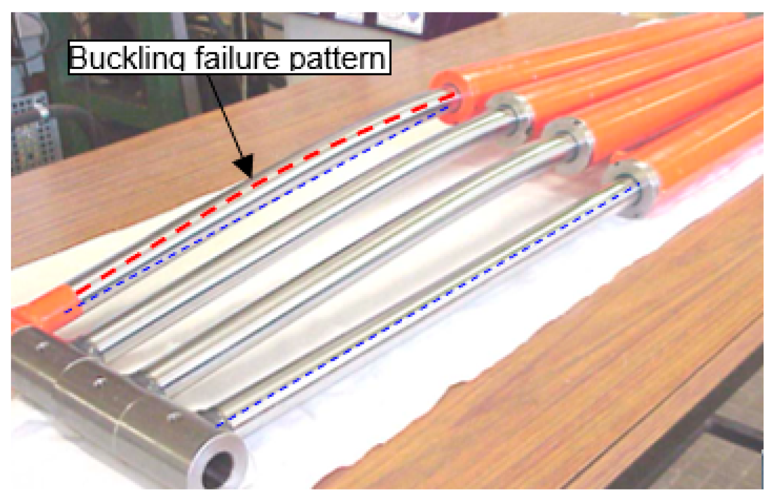
Figure 3.
Cylinder design: weight vs. price [5].
Figure 3.
Cylinder design: weight vs. price [5].
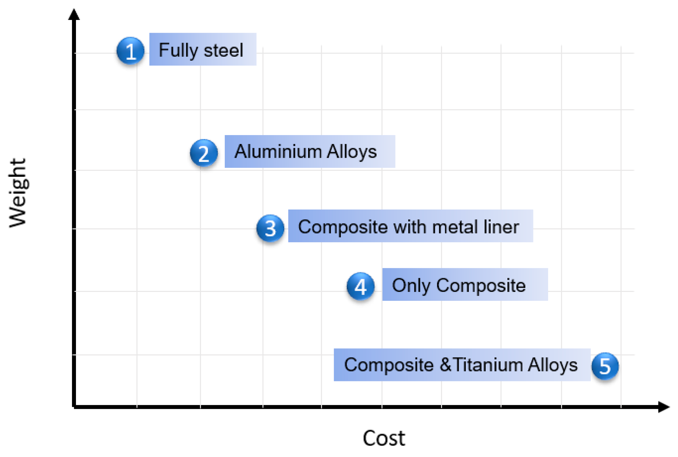
Figure 4.
Filament winding method.
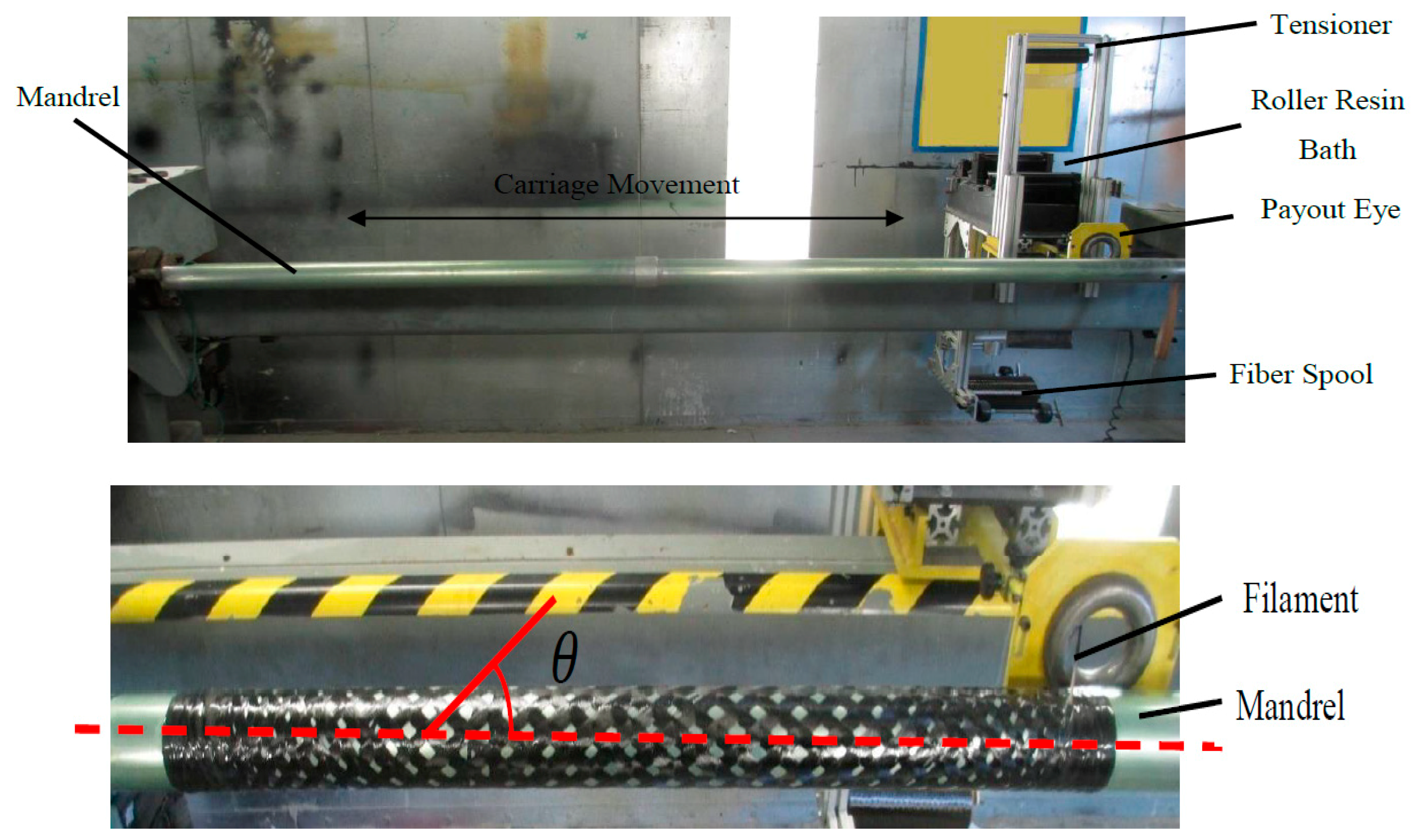
Figure 5.
Slenderness ratio vs. buckling stress [5].
Figure 5.
Slenderness ratio vs. buckling stress [5].
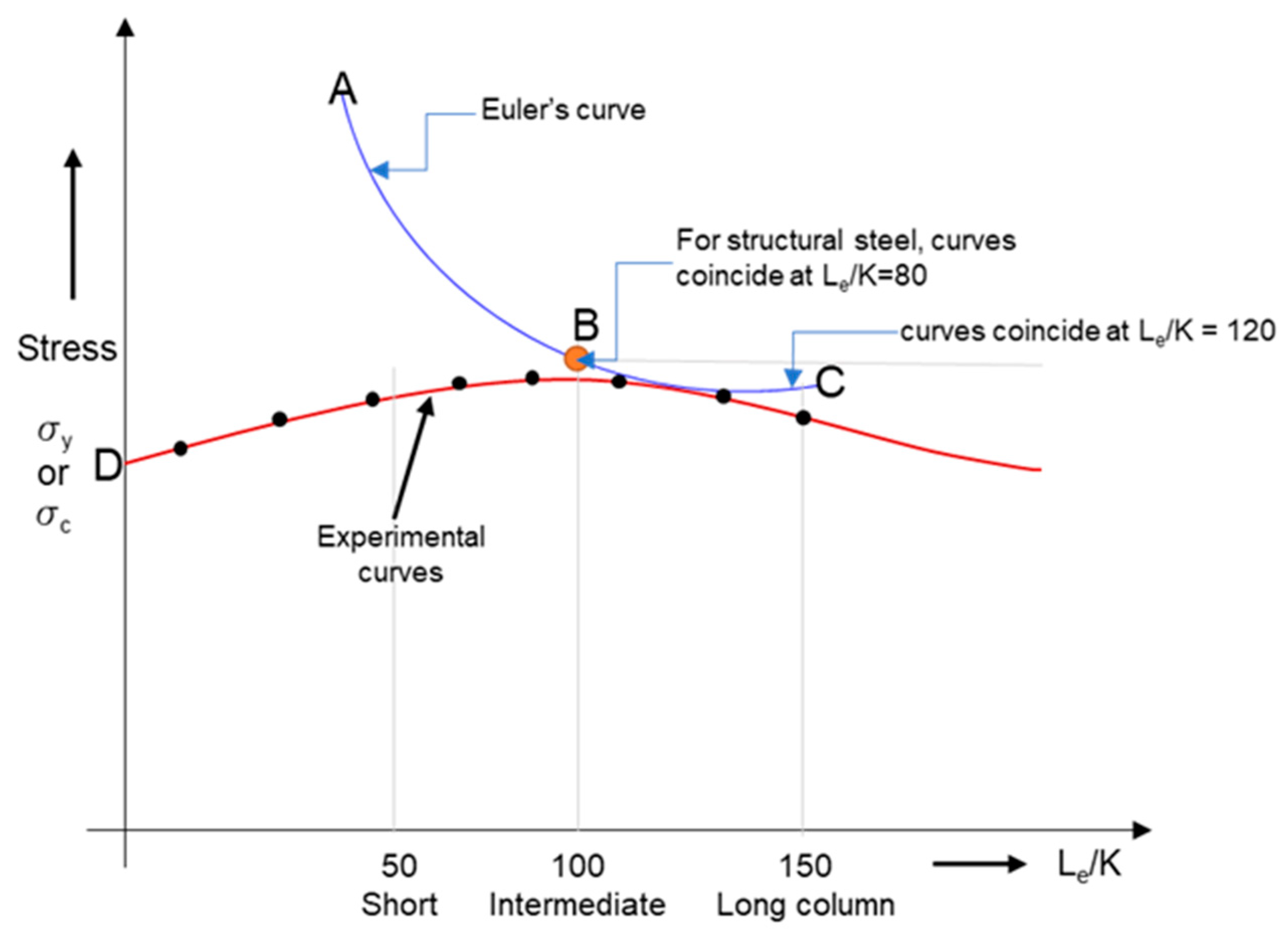
Figure 6.
Schematic diagram of test setup.
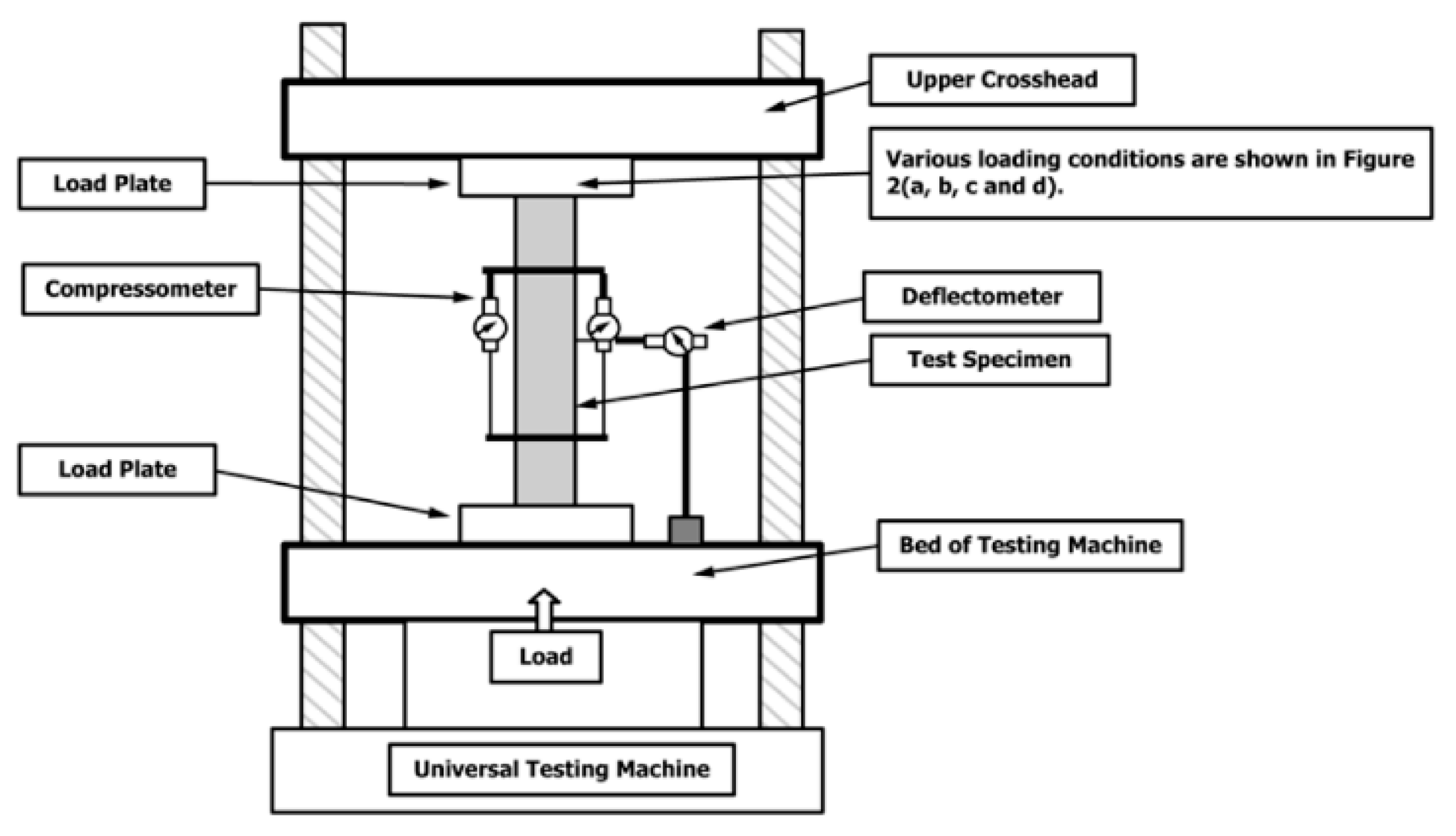
Figure 7.
Experimental analysis of the test sample.

Figure 8.
Failure modes of steel and hybrid rods after testing.
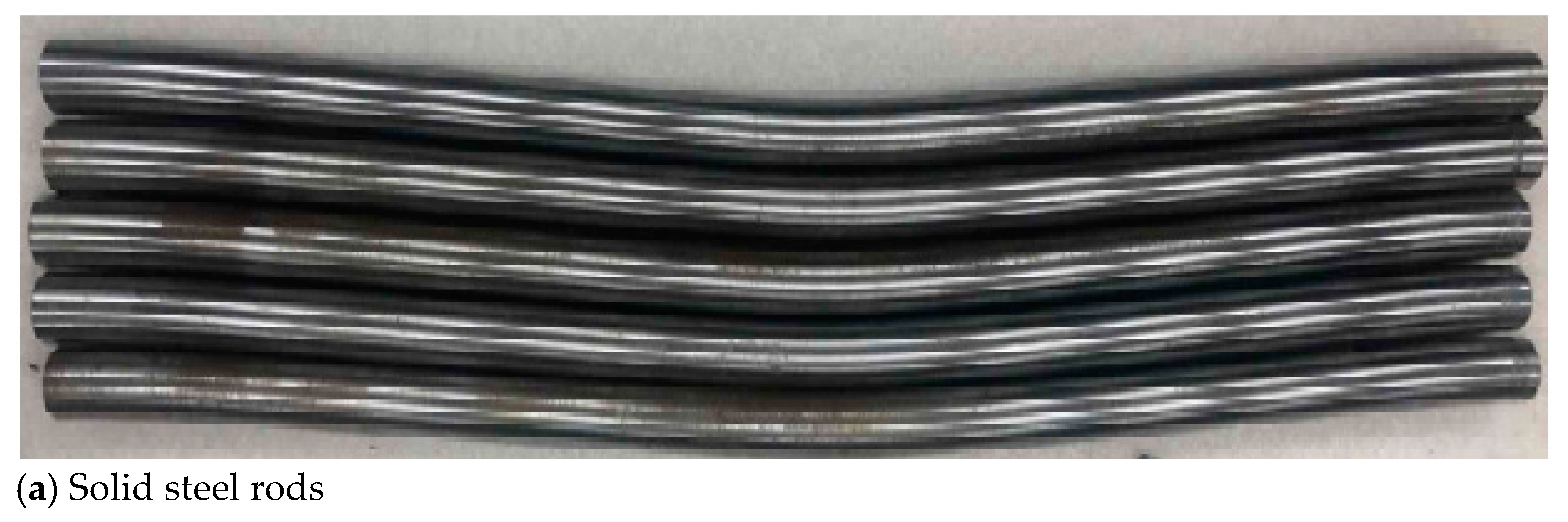
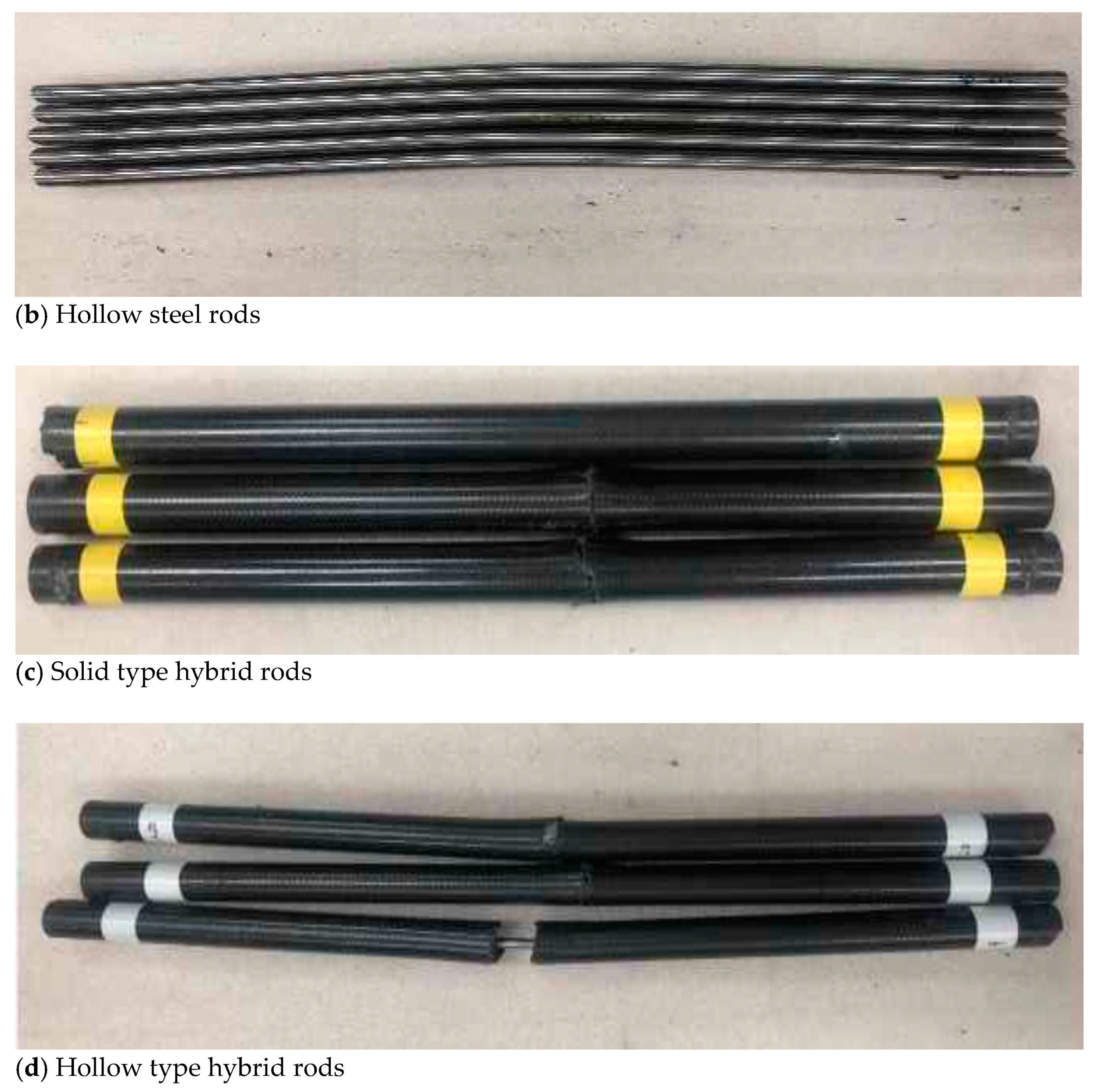
Figure 9.
Numerical model built using ABAQUS.
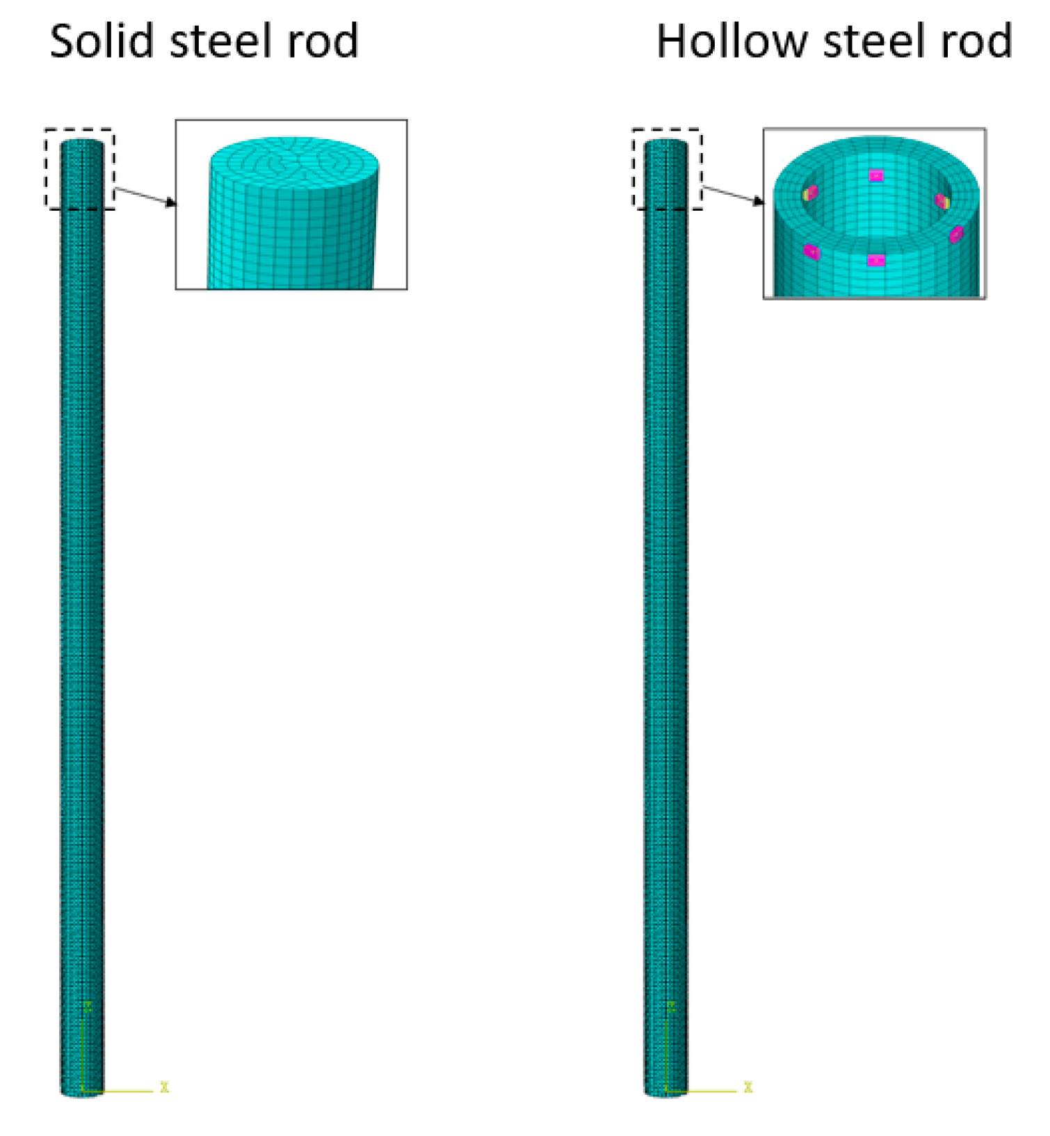
Figure 10.
Numerical results—buckling mode of a steel rod under FEA.

Figure 11.
Variation of buckling load in hybrid rod with respect to No. of laminate plies in CFRP.
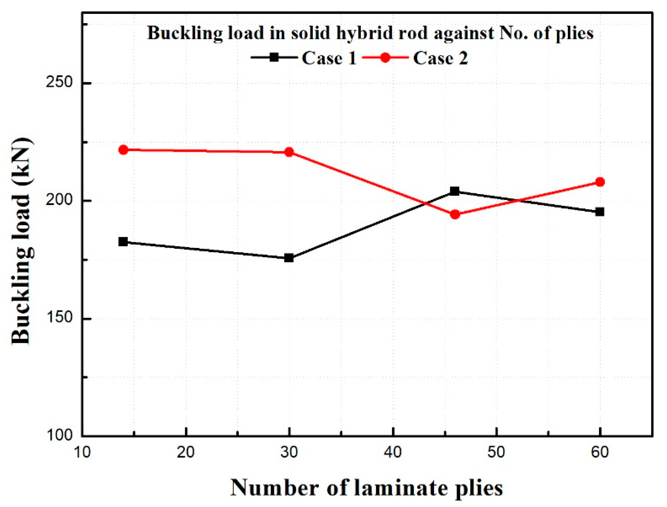
Figure 12.
Variation of buckling load as a function of the number of 0° plies in CFRP.
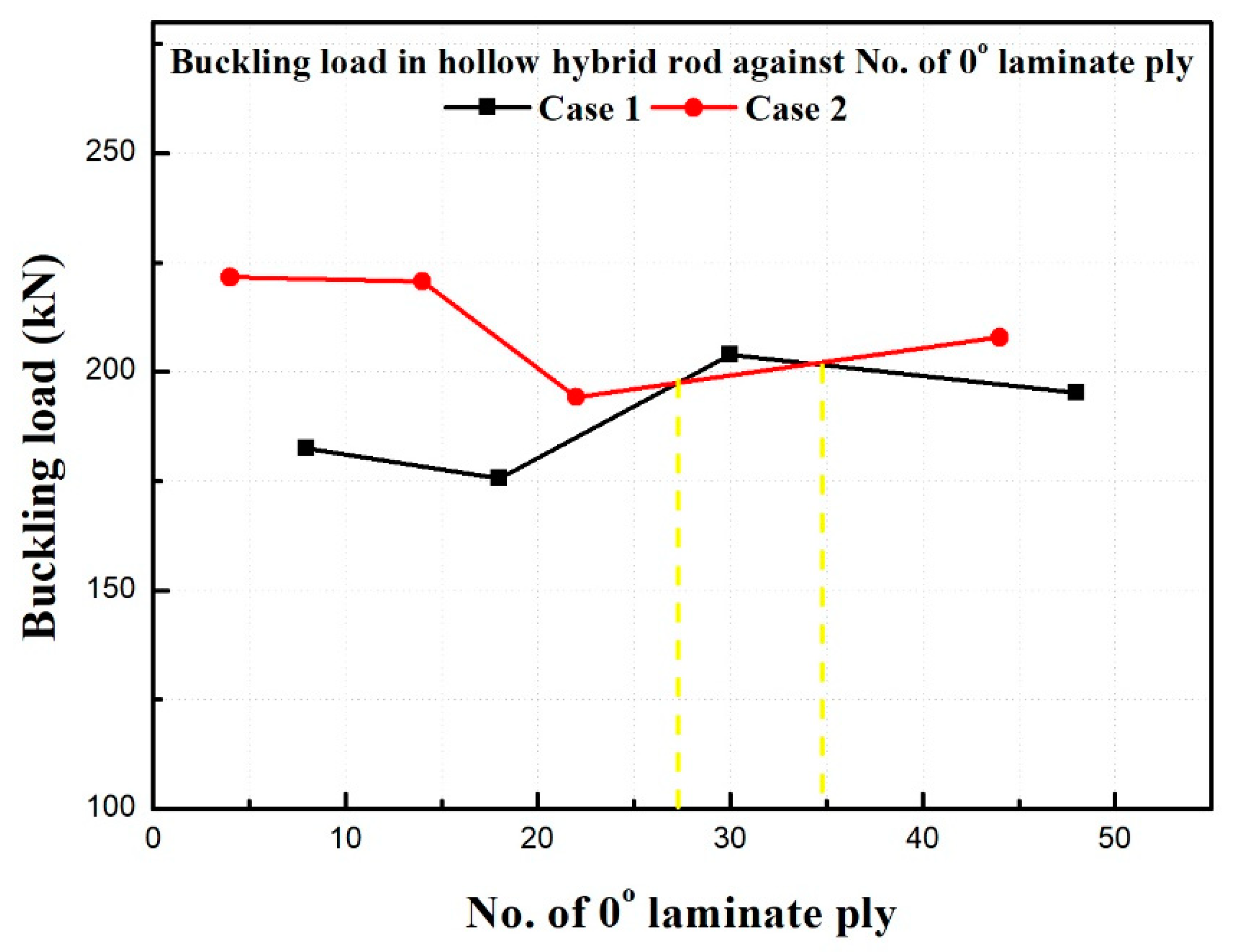
Figure 13.
Variation of buckling load against 45° ply laminate in CFRP.

Figure 14.
Variation of buckling load with respect to 90° ply laminate in CFRP.
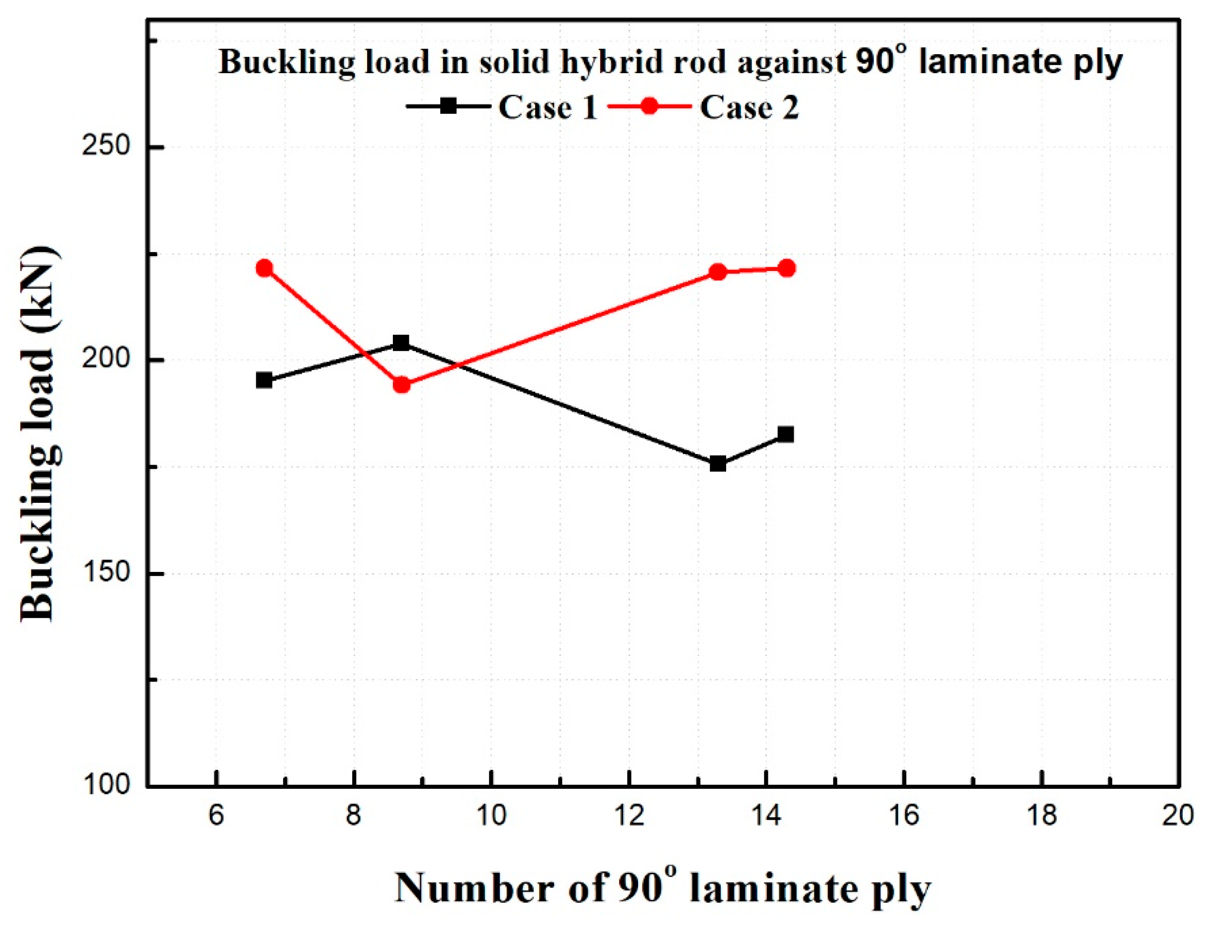
Figure 15.
Variation of buckling load as a function of the number of laminates in CFRP.

Figure 16.
Change in buckling load as a function of percentage of 0° ply laminates used in CFRP.
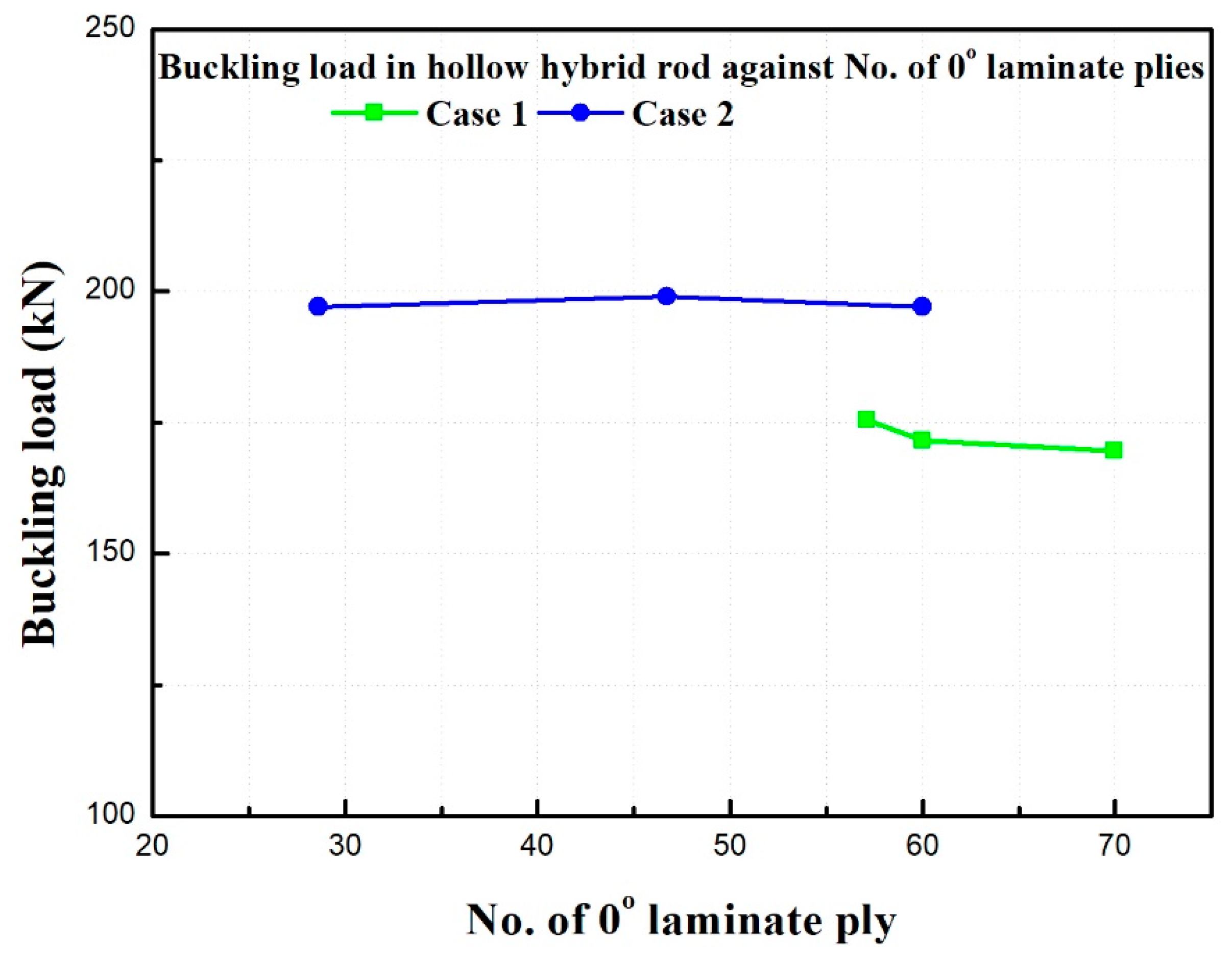
Figure 17.
Change in buckling load as a function of the percentage of 45° laminate in the CFRP.
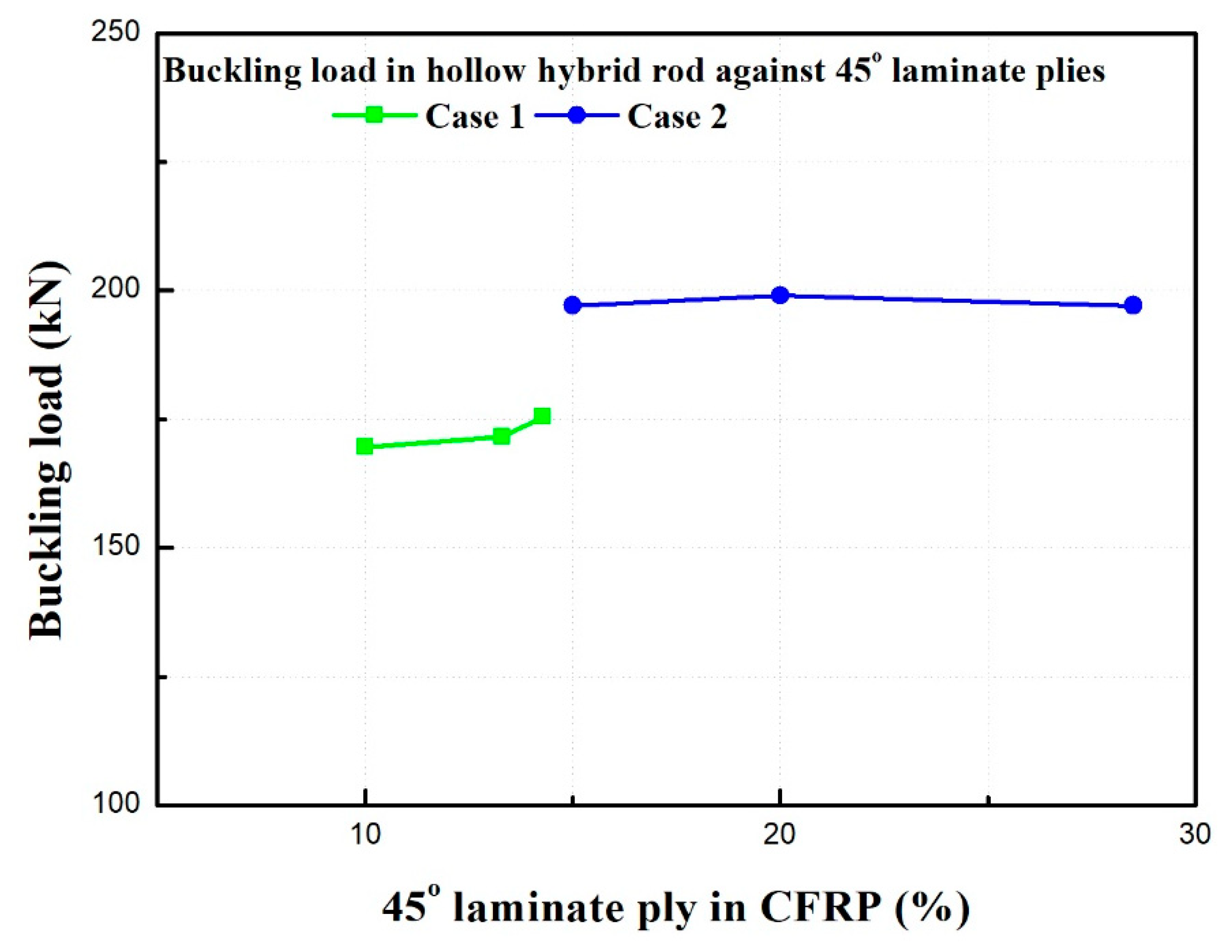
Figure 18.
Change in buckling load as a function of percentage of 90° laminate in CFRP.


Table 1.
Slenderness ratio.
| S.No | Slenderness Ratio | Type of Column | Mode of Failure |
|---|---|---|---|
| 1 | Between 0 to 40 | Short Column | Crushing |
| 2 | Between 40 to 125 | Intermediate Column | Combined crushing & Buckling |
| 3 | Greater than 125 | Long Column | Buckling |
Table 2.
Mechanical properties of steel rod.
| Steel | Elastic Modulus Es [MPa] | Yield Strength Ys [MPa] | Poisson’s Ratio |
|---|---|---|---|
| AISI 1045 | 206,000 | 530 | 0.29 |
Table 3.
Mechanical properties of CFRP.
| Continuous Reinforcement | Tensile Modulus Ef [MPa] | Tensile Strength sf [MPa] | Density rf [g/cm3] |
| Intermediate | 300,000 | 5500 | 1.80 |
| Modulus (IM) | |||
| Carbon Fiber | |||
| Matrix | Tensile Modulus Em [MPa] | Tensile Strength sm [MPa] | Density rm [g/cm3] |
| Epoxy | 3800 | 100 | 1.22 |
Table 4.
Theoretical, numerical and experimental results of steel (only) column.
| Steel Rod Type | Outer Diameter (mm) | Inner Diameter (mm) | Length (mm) | Young’s Modulus (N/mm2) | Slenderness Ratio (No Unit) | Buckling Load (kN) | ||
|---|---|---|---|---|---|---|---|---|
| Theoretical | Numerical | Experimental | ||||||
| Solid | 7.50 | - | 650.00 | 206,000 | 346.67 | 2.94 | 2.92 | 3.79 |
| 15.00 | - | 650.00 | 206,000 | 173.33 | 34.32 | 39.13 | 41.31 | |
| 22.50 | - | 650.00 | 206,000 | 115.56 | 114.74 | 121.36 | 120.72 | |
| 30.00 | - | 650.00 | 206,000 | 86.67 | 280.39 | 297.32 | 291.26 | |
| Hollow | 15.00 | 10.00 | 650.00 | 206,000 | 144.22 | 28.66 | 25.12 | 29.43 |
| 22.50 | 10.00 | 650.00 | 206,000 | 105.60 | 101.99 | 106.31 | 110.09 | |
| 30.00 | 10.00 | 650.00 | 206,000 | 82.22 | 246.09 | 231.34 | 257.92 | |
Table 5.
Experimental data for hybrid (Steel + CFRP) rods.
| Rod Type | Sample | CFRP Volume % | No of Laminate Plies | Laminate Orientation | Experimental Buckling Load kN | Weight in Kg | |||
|---|---|---|---|---|---|---|---|---|---|
| 0° | 45° | −45° | 90° | ||||||
| Solid steel rod | 0 | 0 | 0 | 0 | 0 | 0 | 291.26 | 3.6 | |
| Hybrid Solid | Case 1 | 25 | 14 | 8 | 2 | 2 | 2 | 182.40 | 2.30 |
| 50 | 30 | 18 | 4 | 4 | 4 | 175.54 | 1.38 | ||
| 75 | 46 | 30 | 6 | 6 | 4 | 203.98 | 0.84 | ||
| 100 | 60 | 48 | 4 | 4 | 4 | 195.15 | 0.66 | ||
| Case 2 | 25 | 14 | 4 | 4 | 4 | 2 | 221.63 | 2.32 | |
| 50 | 30 | 14 | 6 | 6 | 4 | 220.65 | 1.40 | ||
| 75 | 46 | 22 | 10 | 10 | 4 | 194.17 | 0.86 | ||
| 100 | 60 | 44 | 6 | 6 | 4 | 207.90 | 0.68 | ||
| Hollow steel rod | 0 | 0 | 0 | 0 | 0 | 0 | 257.92 | 3.18 | |
| Hybrid Hollow | Case 1 | 25 | 14 | 8 | 2 | 2 | 2 | 175.55 | 1.90 |
| 50 | 30 | 18 | 4 | 4 | 4 | 171.62 | 0.98 | ||
| 100 | 40 | 28 | 4 | 4 | 4 | 169.66 | 0.58 | ||
| Case 2 | 25 | 14 | 4 | 4 | 4 | 2 | 197.12 | 1.92 | |
| 50 | 30 | 14 | 6 | 6 | 4 | 199.08 | 1.00 | ||
| 100 | 40 | 24 | 6 | 6 | 4 | 197.12 | 0.60 | ||
Publisher’s Note: MDPI stays neutral with regard to jurisdictional claims in published maps and institutional affiliations. |
© 2021 by the authors. Licensee MDPI, Basel, Switzerland. This article is an open access article distributed under the terms and conditions of the Creative Commons Attribution (CC BY) license (https://creativecommons.org/licenses/by/4.0/).
Share and Cite
MDPI and ACS Style
S P, P.K.; Lee, S.-S. Design and Experimental Analyses of Hybrid Piston Rods Used in Hydraulic Cylinders under Axial Load. Appl. Sci. 2021, 11, 8552. https://doi.org/10.3390/app11188552
AMA Style
S P PK, Lee S-S. Design and Experimental Analyses of Hybrid Piston Rods Used in Hydraulic Cylinders under Axial Load. Applied Sciences. 2021; 11(18):8552. https://doi.org/10.3390/app11188552
Chicago/Turabian StyleS P, Praveen Kumar, and Seok-Soon Lee. 2021. "Design and Experimental Analyses of Hybrid Piston Rods Used in Hydraulic Cylinders under Axial Load" Applied Sciences 11, no. 18: 8552. https://doi.org/10.3390/app11188552
Note that from the first issue of 2016, this journal uses article numbers instead of page numbers. See further details here.