
Design Study for a New Spanner

1
Department of Mechanical Engineering (Jiangong Campus), National Kaohsiung University of Science and Technology, Kaohsiung 80778, Taiwan
2
Department of Chemical & Materials Engineering (Jiangong Campus), National Kaohsiung University of Science and Technology, Kaohsiung 80778, Taiwan
*
Authors to whom correspondence should be addressed.
Appl. Sci. 2021, 11(19), 8878; https://doi.org/10.3390/app11198878
Submission received: 10 August 2021
/
Revised: 12 September 2021
/
Accepted: 21 September 2021
/
Published: 24 September 2021
(This article belongs to the Topic Industrial Engineering and Management)
Abstract
:A replacement for the original F-spanner is designed using computer-aided engineering (CAE) and the Taguchi method. In the design process, the L9(34) orthogonal table was used for parameter design. Four control factors are used: outer diameter, bend radius, angle, and connected fillet. Each factor is set to three levels with numerical analysis using ANSYS software. After performing an optimization analysis for the combination parameters, the prototype is created by rapid-prototyping (RP) and is found to improve operational safety in a piping system.
1. Introduction
Stop valve designs often integrate a hand wheel to increase torque, thus improving fluid flow control. Fluids in piping systems are often viscous due to a lack of service maintenance, causing stop valve resistance that can be difficult to overcome using a conventional F-type spanner. During operation, the front paws straddle the two rods of the hand wheel, and the rear paws are placed outside the hand wheel and rotate to apply torque, as shown in Figure 1.
The force arm of this structure does not pass through the torque center, and there is a deviation of the angle a, which causes loss of power. Angle a increases with the distance between the two points AB. The larger the angle a, the more serious the loss of power. To improve the inconvenience of the traditional F-spanner and to meet the needs of engineers, we present a new spanner concept (ROC patent no. M474597 [1]), providing a brief design overview, numerical analysis, and experimental results.
2. Design Concept
Traditional oil refinery stop valves of different sizes (4″, 6″, and 8″) all use a five-spoke design, with each segment between the two spokes at 72° (see Figure 2).
As shown in Figure 3, for such a valve, a spanner requires a trapezoidal block that can fit completely and stably between two spokes for safe operation without slippage.
A trapezoidal block can be constructed to fit between the two spokes, allowing for safe stress concentrations, using chamfered edges and corners. We thus design the new spanner concept presented in Figure 4.
The developed spanner has the following advantages: (1). It occludes the handwheel with no relative movement; (2). the spanner arm moment arm passes directly through the center of rotation, thus reducing effort; (3). it is chamfered to avoid collision with the handwheel; and (4). a single spanner can be used for valve wheels of different diameters.
3. Design Experiment
Based on the above design concept, we use computer-aided engineering (CAE) techniques to analyze spanner operations with different valve wheel sizes. The Taguchi method [2] is a crucial part of engineering design, especially for product development and improvement. To reduce the weight of the finished product, the spanner handle was designed based on four design factors (Figure 5): A: outer diameter, B: bend radius, C: angle, and D: connected fillet.
Table 1 shows the maximum and minimum boundaries of the new spanner size. The other constants are as follows:
- (1)
- Material: Aluminum Alloy;
- (2)
- Allowed Tensile strength: 280 (MPa);
- (3)
- Capability stress of bend torque (M): 100 (N-m);
Before the analysis, the value of the force moment must be defined. Assuming an ordinary person can output 300 N and the force arm is 30 cm, then
We set torque at 100 (N-m).
- (4)
- ANSYS [3] numerical analysis setting:
- (A)
- Element type: SOLID187;
- (B)
- Node No.:45885; and
- (C)
- Meshing method: Free mesh (tetrahedron).
The orthogonal Array (L9) is used to assign the design parameters and interactions to various columns of the orthogonal array. The design parameter combination for each numerical analysis using ANSYS software [3] is shown in Table 2 and Figure 6.
From the response diagrams of each factor, it can be seen that the best level combination should be A3B2C3D3 and the optimal design size shown in Table 3.
According to the above analysis result, the maximum von Mises stress is concentrated on the connection between handle and the trapezoid in 138.5 MPa, as shown in Figure 7.
4. Concluding Remarks
The Taguchi method can be used to obtain fine design figures using computer-aided engineering. A new spanner is designed for use with stop valves, providing fast and safe manual valve operations in piping system.
Author Contributions
Investigation, M.-C.L.; methodology, M.-C.L.; supervision, M.-C.L.; writing—review and editing, T.-H.H. Both authors have read and agreed to the published version of the manuscript.
Funding
This research received no external funding.
Institutional Review Board Statement
Not applicable.
Informed Consent Statement
Not applicable.
Data Availability Statement
Not applicable.
Acknowledgments
This study received financial support provided from the National Kaohsiung University of Science and Technology under grant No. 110E9010BA02.
Conflicts of Interest
The authors declare no conflict of interest.
References
- Lin, M.C.; Wang, C.T.; Fu, Y.D. Trapezoid Wrench. Patent No. M474597; Taipei, Taiwan, 21 March 2014. [Google Scholar]
- Montgomery, D.C. Design and Analysis of Experiment, 5th ed.; John Wiley & Sons: New York, NY, USA, 2001. [Google Scholar]
- Swanson Analysis System Inc. Ansys User’s Manual, Revision 14.5; Element (Software Manual); Swanson Analysis System Inc.: Canonsburg, PA, USA, 2013. [Google Scholar]
Figure 1.
F-spanner concept.
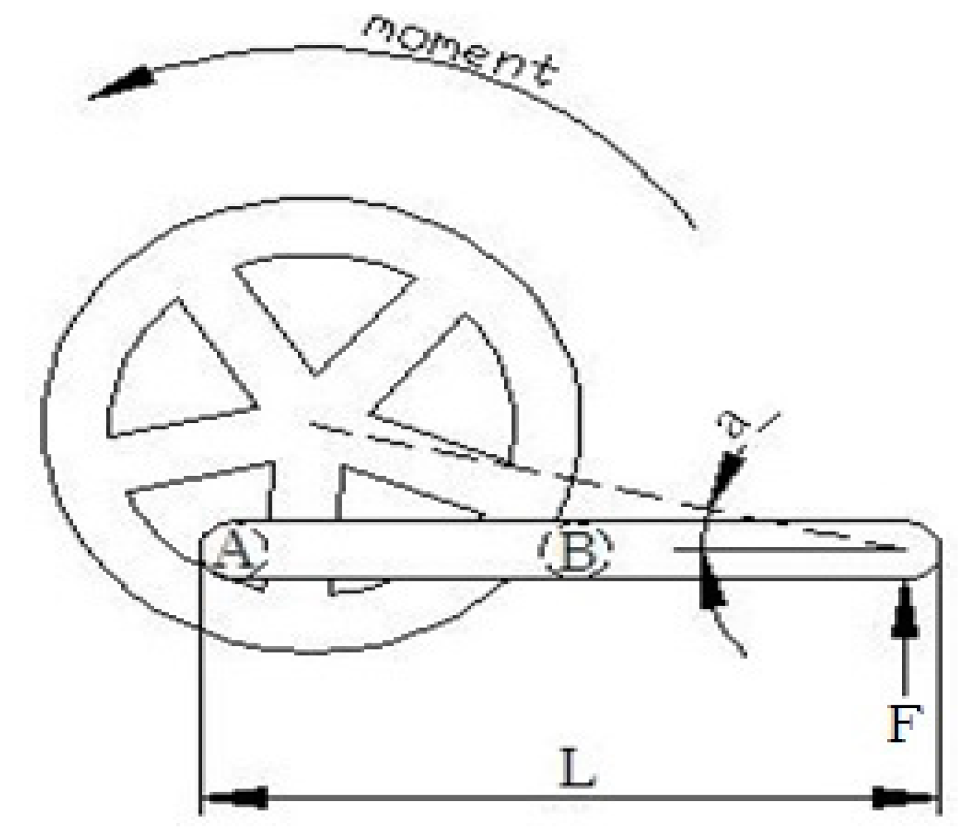
Figure 2.
Basic five-spoke stop valves.
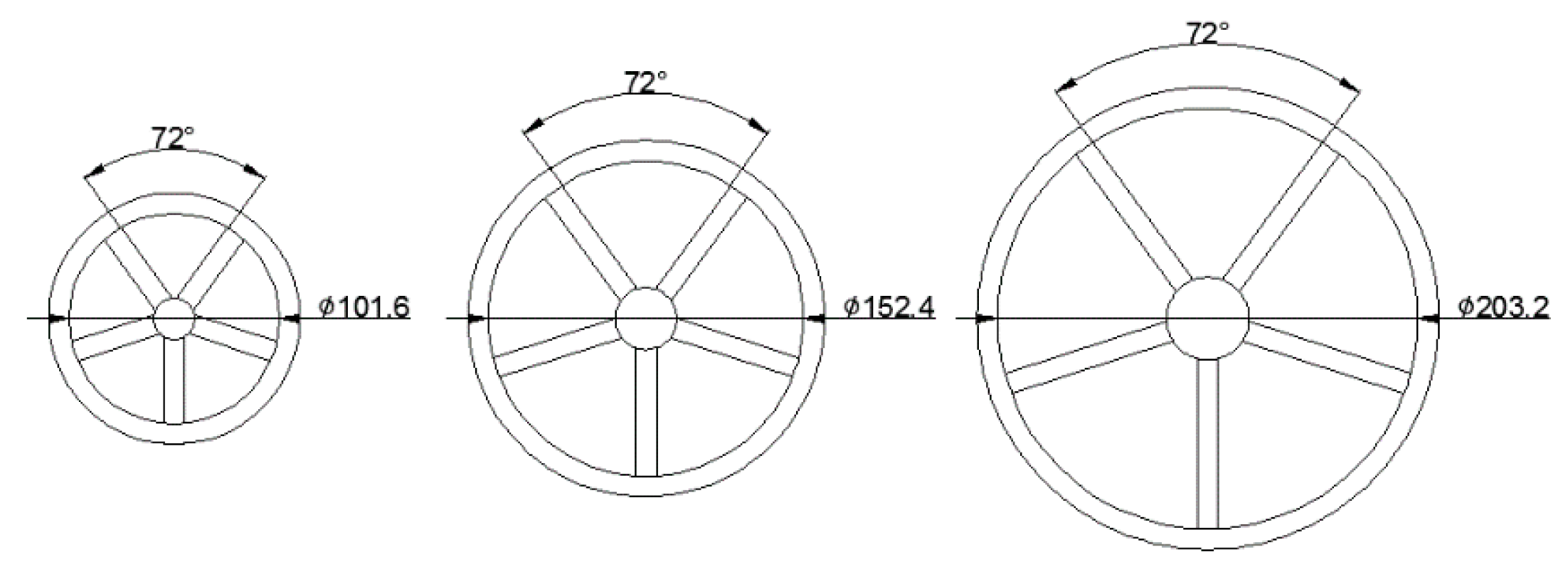
Figure 3.
Trapezoidal block.
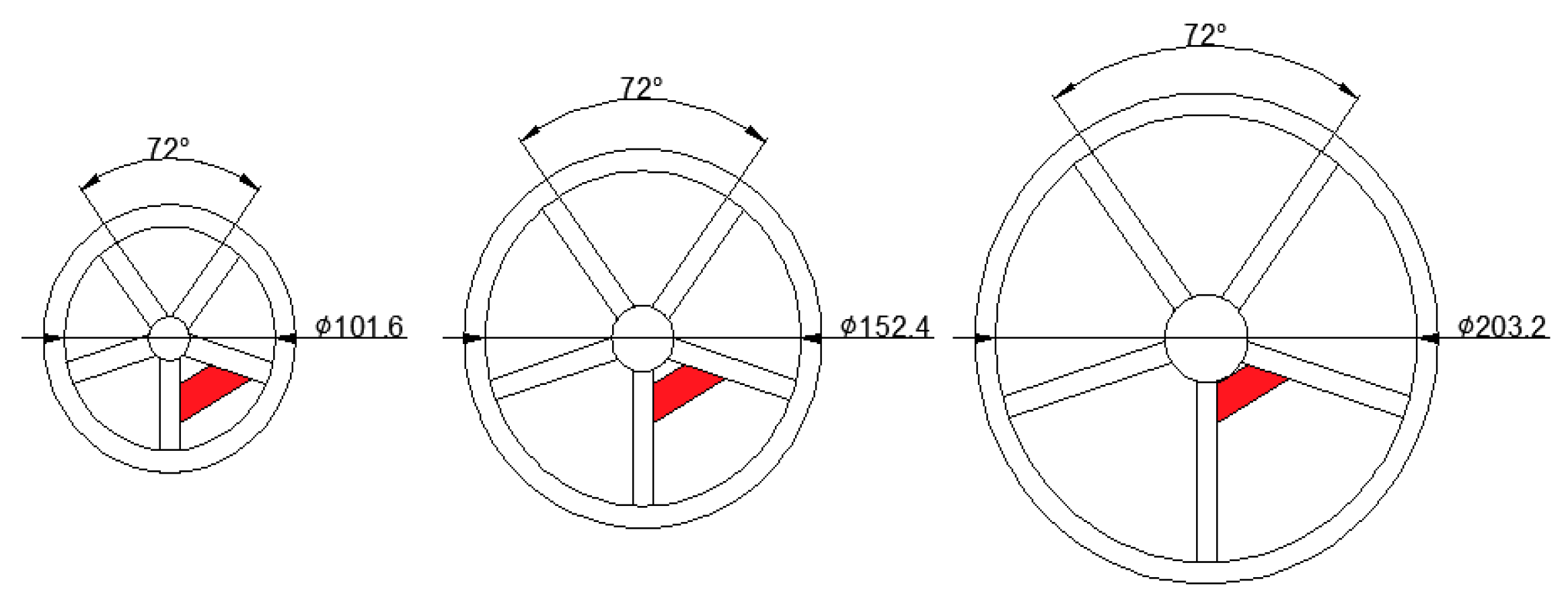
Figure 4.
Novel spanner concept.
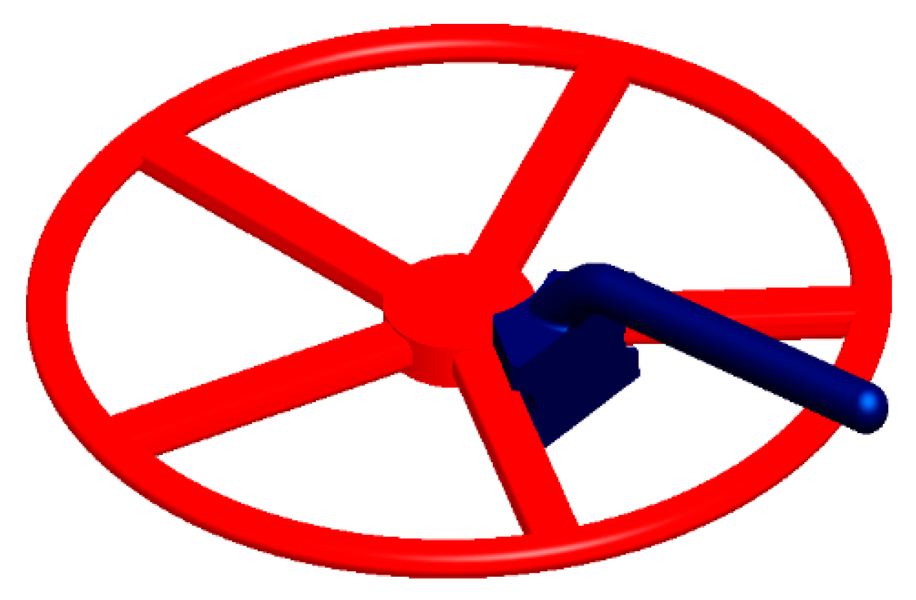
Figure 5.
Size parameters of the new spanner.
Figure 6.
Factor S/N ratio of the new spanner.
Figure 7.
Stress analysis of optimal design combination.

Figure 8.
(a) Spanner protype and (b) 3D-printed schematic.


Table 1.
Design parameters and limitations.
| Factor | Factor Code | Level 1 | Level 2 | Level 3 |
|---|---|---|---|---|
| Outer diameter | A | 20 mm | 22 mm | 24 mm |
| Bend radius | B | 33 mm | 35 mm | 37 mm |
| Angle | C | 45° | 50° | 55° |
| Connected fillet | D | 0.25 mm | 0.5 mm | 0.75 mm |
Table 2.
Design parameters values per L9 orthogonal array.
| Factor No. | A (mm) | B (mm) | C (Degree) | D (mm) | Von Mises Stress (MPa) | S/N Ratio |
|---|---|---|---|---|---|---|
| 1 | 20 | 30 | 45 | 0.25 | 430.54 | −52.6803 |
| 2 | 20 | 35 | 50 | 0.50 | 307.57 | −49.7589 |
| 3 | 20 | 40 | 55 | 0.75 | 230.68 | −47.2602 |
| 4 | 22 | 30 | 50 | 0.75 | 199.93 | −46.0176 |
| 5 | 22 | 35 | 55 | 0.25 | 286.21 | −49.1337 |
| 6 | 22 | 40 | 45 | 0.50 | 253.23 | −48.0703 |
| 7 | 24 | 30 | 55 | 0.50 | 194.20 | −45.7650 |
| 8 | 24 | 35 | 45 | 0.75 | 146.87 | −43.3387 |
| 9 | 24 | 40 | 50 | 0.25 | 285.98 | −49.1267 |
Table 3.
Optimal design size combination.
| Factor | Factor Code | Best Results |
|---|---|---|
| Outer diameter | A | 24 mm |
| Bend radius | B | 35 mm |
| Angle | C | 55° |
| Connected fillet | D | 0.75 mm |
Publisher’s Note: MDPI stays neutral with regard to jurisdictional claims in published maps and institutional affiliations. |
© 2021 by the authors. Licensee MDPI, Basel, Switzerland. This article is an open access article distributed under the terms and conditions of the Creative Commons Attribution (CC BY) license (https://creativecommons.org/licenses/by/4.0/).
Share and Cite
MDPI and ACS Style
Lin, M.-C.; Ho, T.-H. Design Study for a New Spanner. Appl. Sci. 2021, 11, 8878. https://doi.org/10.3390/app11198878
AMA Style
Lin M-C, Ho T-H. Design Study for a New Spanner. Applied Sciences. 2021; 11(19):8878. https://doi.org/10.3390/app11198878
Chicago/Turabian StyleLin, Ming-Che, and Tsung-Han Ho. 2021. "Design Study for a New Spanner" Applied Sciences 11, no. 19: 8878. https://doi.org/10.3390/app11198878
Note that from the first issue of 2016, this journal uses article numbers instead of page numbers. See further details here.