Article

Optimization of a Coherent Dual-Beam Array Feed Network for Aperiodic Concentric Ring Antennas

by
Armando Arce
1,2,*,
Enrique Stevens-Navarro
2,
Ulises Pineda-Rico
2,
Marco Cardenas-Juarez
2,
Francisco R. Castillo-Soria
2 and
David H. Covarrubias
3
1
Cátedras CONACYT, Universidad Autónoma de San Luis Potosí (UASLP), San Luis Potosí 78290, Mexico
2
Facultad de Ciencias, Universidad Autónoma de San Luis Potosí (UASLP), San Luis Potosí 78290, Mexico
3
Electronics and Telecommunications Department, CICESE Research Center, Carretera Ensenada-Tijuana No.3918, Zona Playitas, Ensenada 22860, Mexico
*
Author to whom correspondence should be addressed.
Appl. Sci. 2021, 11(3), 1111; https://doi.org/10.3390/app11031111
Submission received: 3 December 2020 / Revised: 19 January 2021 / Accepted: 21 January 2021 / Published: 26 January 2021
(This article belongs to the Special Issue New Trends in Telecommunications Engineering)

Abstract

:
A dual-beam coherent feeding system design approach with a non-uniform layout on a concentric ring array is described and synthesized. In this case, the feeding system is based on a reconfigurable topology composed of a set of alternated power dividers and combiners, providing coherent in-phase outputs. Thus, in this paper, a two-beam architecture based on a coherent feeding system formed by a set of intercalated input signals feeding each circular ring in a non-uniform antenna array with multi-beam shaping and steering features is analyzed. The task of optimizing the aperiodic layout on the shared aperture based on the radii of the circular rings is realized by the differential evolution method. Numerical experiments grounded in antenna synthesis validate the capabilities and improved performance of the proposed dual-beam configuration with a non-uniform layout in contrast with its uniform counterpart, with enhanced performance on average by up to −6.1 dB for sidelobe level and 3.5 dB for directivity. Additionally, the results show a significantly less complex two-beam feeding network in contrast with the case of a typical electronically scanned array—in this proposal, each direction of maximum radiation is conformed and scanned with approximately half of the control inputs.

1. Introduction

Arrays of antennas are a fundamental actor and base in wireless communication systems, where a group of radiators can perform advanced features synthesizing one or more beam patterns of arbitrary shape. These antenna arrays extend the capabilities of mono-element antennas, improving their overall performance. Hence, increasing the number of antennas can improve the antenna system’s capabilities in some cases with multiple shaped and directive beams, power pooling, element redundancy, angular diversity, and electronic beam scanning (phased arrays). However, these multi-beam antennas are not a single entity and their function relies on an underlying feeding system, usually a beamforming network (BFN) subsystem that is an essential component for feeding and combining the array element’s signals [1]. For fixed beams, a single high directive antenna without a feeding network could also be an alternative to arrays [2].
As a result of the continuous advancement of telecommunication systems (e.g., 5G mobile communications and beyond), a real need and motivation have arisen focused on the evolution and improvement of antenna systems. In light of this, the main goal of research in this field has been to increase the global antenna performance and at the same time reduce the major issues in these systems related to cost and complexity [3,4]. Within this framework, the aperiodicity of antenna arrays could be a solution to enhance the antenna system’s capabilities and even minimize the use of some radiators. Nevertheless, the design and optimization of aperiodic arrays usually become a complex target, where in addition to the complexity of the aperiodicity of the layout, the inclusion of a multiple-beam feeding system in the synthesis makes this task more challenging.
Specifically, dual-beam antenna systems are useful in different mobile applications including terrestrial and space systems, such as microwave close-range sensors, automotive radar sensors, synthetic aperture radar (SAR) systems, tracking satellites, autonomous sensor networks, and base stations, among others [5,6]. Nevertheless, there are varying approaches to conform two beams with pros and cons, and trade-offs between them. Some antenna system architectures involve the use of certain types of radiators and feeders working together [7]—typical examples include planar leaky wave antennas (LWA) with different methods of feeding network to control the leaking rate, direction, and polarization [8]. Similarly, transmit arrays as a beamforming network are another example of a dual-beam solution grounded on the behavior of frequency selective surfaces and transmitting/receiving elements [9,10]. In the same vein, phased arrays are a cornerstone for dual/multi-beam beamforming and beam steering in infrastructure applications [11], sometimes combined with reflectarray apertures [12] or even feeding the array with a peripherally excited (PEX) metallic cavity [4]. Some other typical applications use classical lossless matrices or hybrids using related circuitry as beamforming networks [13,14].
However, the aforementioned dual-beam approaches deal with different drawbacks, including a cumbersome mechanism for beam scanning or fixed beams, interference between signals caused by adjacent antennas, and limited beam pointing or beam shaping, among others. Nevertheless, an alternative proposal is based on coherent in-phase networks, improving flexibility and reconfigurability with refined beam shaping and scanning (electronically) capabilities. In previous years, a coherent feeding system relying on identical substructure components known as coherently radiating periodic structures was presented in [15]. The feeding system for a phased array was described in [16], showing the working principles to implement a beamforming network topology in a basic antenna array, minimizing the difficulty of the associated control to scan the beam. As an antenna synthesis problem with optimization, the antenna system with a periodic aperture in different antenna geometries and parameters has been widely studied, and some related investigations can be found in [17,18,19]. Recently, early work on non-uniform apertures working together with coherent feeding systems in circular antenna arrays was addressed in [20] and a mono-beam investigation in concentric rings was analyzed in [21].
This paper presents a dual-beam analysis of an antenna system’s performance that exploits a non-uniform aperture with concentric ring antennas, employing a minimalistic architecture based on coherently radiating periodic structures with multi-beam steering capabilities. In this approach, the antenna system is optimized in such a way that the radii on the antenna array are improved by a well-known evolutionary optimizer. Furthermore, a benchmarking study with a periodic aperture and the same feeding system with contrasting directivity (D) and sidelobe level (SLL) is implemented and validated by the antenna synthesis’ numerical experiments.
The remainder of this paper is structured as follows: the mathematical expressions of a non-uniform layout on concentric ring antennas, the general theory behind coherent periodic structures acting as a beamforming network, and the methodology to optimize the antenna system are presented in Section 2. Section 3 addresses the numerical examples set out for the two-beam feeding system configuration and the parameters used in the metaheuristic optimizer, and at the end, the numerical examples for the dual-beam array feed are assessed and reviewed. Some concluding remarks are presented in Section 4.

2. Problem Formulation

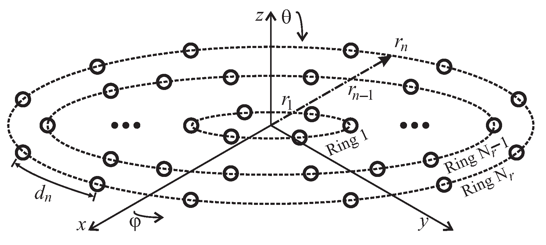
2.1. Aperiodicity in Concentric Ring Arrays

An aperiodic or non-uniform array is considered when the interelement spacing of antenna elements is not equal between them. Thus, consecutive rings conformed by antenna elements in a circular layout which share the same origin where each ring has its own radius within an aperiodic layout (different interelement distances or radii between rings) are known as aperiodic concentric ring arrays (ACRAs). In general, let us consider a concentric geometry, assuming N r circular rings with N e radiators for each ring which are deployed in the x y plane, as illustrated in Figure 1. The far-field pattern considering an arbitrary complex excitation set ( w m n ) without a radiator in the center of the array can be calculated as [22]:
A F ( θ , φ ) = n = 1 N r m = 1 N e w m n exp [ j k [ x n m ( u ) + y n m ( v ) ] ] ,
where x n m = r n cos φ n m and y n m = r n sin φ n m define the antenna element locations, the antenna elements’ deployment around the rings is indicated by φ n m = 2 π ( m 1 ) / N e , and r n denotes the radial distance per ring from the origin of the antenna array until the last ring. The u v space considering the excitation phases is defined by u = sin θ cos φ sin θ 0 cos φ 0 and v = sin θ sin φ sin θ 0 sin φ 0 . The steering angle for translation is denoted by ( θ 0 , φ 0 ) ; in this case, θ is the angular direction in elevation and φ is the spatial angle for the azimuth. Finally, the wavelength λ is related to the angular wavenumber k = 2 π / λ in Equation (1).
Assuming a multi-beam scenario, the array factor is simultaneously optimized with p beams, considering the aperiodicity in function of the different radius in each ring r and an isophoric array feeding [23,24,25], the A F can be written as follows:
A F p ( θ , φ , r ) = n = 1 N r m = 1 N e exp [ j k r n ( u cos φ n m + v sin φ n m ) ] ,
In the following section, the theoretical model of the feeding subsystem for the ACRA is described.

2.2. Coherent BFN Model

In this paper, a coherent feeding network with dual-beam shaping and steering capabilities is used in combination with an ACRA in our numeric experimentation. The feeding system relies on the working principles of coherently radiating periodic structures implemented as a beamforming network (also known for its acronym as C-BFN). This feeding network, which combines the redirecting beam control and the power distribution network, uses a unit cell periodically and alternately as a power combiner and divider to lead the signals from the input ports to the radiators. In a C-BFN, each input port obeys an in-phase excitation law (true time delay) and the output ports have a Gaussian-shape amplitude distribution [26,27]. Usually, the topology of the coherent network is built by using unit cells along with consecutive layers, as is illustrated in Figure 2. This specific example shows the signal propagation from three different input ports to the shared outputs. In this feeding system, the power throughout the network shows a binomial excitation behavior [15]. The modular arrangement uses the unit cell as a key piece of the network, facilitating the use of distinct topologies for specific design needs. A C-BFN should guarantee an in-phase performance at the output, no matter its periodicity. Practical research of the feeding system relies on implementing unit cells using different multi-port devices [15,26,28].
As shown in Figure 2, a three-port component is implemented for power division and combination, and its behavior can be described as follows [15]:
[ S ] cell = 0 j / 2 j / 2 j / 2 0 0 j / 2 0 0 .
This Wilkinson’s matrix ensures isolation among the inputs with a matching behavior that can be observed at the ports. Assuming transmit mode, a transfer matrix can be applied for assessing the final output of the coherent feeding system, as follows [29]:
α m + 1 ( m + 1 , 1 ) = T m ( m + 1 , m ) · α m ( m , 1 ) ,
where [ α m + 1 ] represents the output of the coherent network using one layer. The above can be extended for more layers if necessary. On the other hand, [ α m ] is the excitation input. In both cases, m represents the feeding ports.
The transfer matrix for the coherent network is expressed as follows:
[ T m ] = 2 / 2 0 0 0 1 / 2 1 / 2 0 0 0 1 / 2 1 / 2 0 0 0 1 / 2 1 / 2 0 0 0 2 / 2 ( N , M ) .
In the transfer matrix, its coefficients are related to the unit cell, as can be observed in (3), in which the rows denote power combination and the columns represent power division. Consequently, it is possible to synthesize this feeding system with a complete antenna system, constructing an architecture that relies on Figure 2 and evaluating (4) and (5).

2.3. Optimization Tool

This subsection briefly describes the procedure to optimize the two-beam antenna pattern and find adequate solutions for the coherent beamforming network. In this specific case, the task is done by applying a global optimization method and the numerical examples in this paper were implemented using the MATLAB software version R2018a. The optimization tool in this work uses hard constraints and specifications in an objective function, finding candidate solutions to achieve quasi-optimal solutions in the multi-beam scenario. The problem to optimize with constraints is correlated with a complex-valued argument (2) in an exponential function associated with the beam patterns and antenna elements positions, dealing with an oscillating and nonlinear behavior.
In order to find the trade-off between maximum directivity and the lowest peak SLL in a predefined angular location for each beam, the antenna synthesis problem can be expressed as an optimization problem with constraints to be minimized, to obtain a quasi-optimal solution of the radius of each ring in the non-uniform concentric array, in the following way:
min r | A F ( θ msl , φ msl , r ) | | A F ( θ max , φ max , r ) | + 1 D ( θ , φ , r ) , s . t . | A F p ( θ max , φ max , r ) | = 1 , r = { r n | r R } , n N r ,
where ( θ msl , φ msl ) is the direction attained by the peak sidelobes on either side of the main beams, ( θ max , φ max ) denote the main beam angles, and the size of the radius domain for each circular ring is indicated by R .
In this case, the optimization process is performed by differential evolution (DE). This algorithm is a proficient and widely used optimizer commonly applied in electromagnetic optimization problems [30]. Summarizing the algorithm in general, the DE optimizer explores for a global optimum solution in a d-dimensional decision space Ψ d . It works through an initial population ( N p o p ) with random initialization (within boundary constraints) of parents or real-valued target vectors (genome/chromosomes). Each vector is a candidate solution that enters into an iterative optimization process for the multi-dimensional problem. After the initialization process, in the optimization cycle that contains three different processes, known as mutation, crossover, and selection, some of the candidate solutions are selected and geometrically perturbed. The central component of DE and the principal strategy on the optimization task is carried out by the genetic operator known as mutation. Mutation creates an intermediate mutant/donor vector υ d for each vector χ i G = [ χ i , 1 G , χ i , 2 G , , χ i , d G ] in the population at the Gth iteration (called iteration), as follows:
υ d G + 1 = χ r 1 G + F ( χ r 2 G χ r 3 G ) .
The scaling factor F indicates a control input (positive) for scaling the difference parameters ( χ r 2 G χ r 3 G ) which defines the length of the exploration, also called the mutation factor. The indices r 1 , r 2 , and r 3 are mutually exclusive integers randomly taken from the population [ 1 , N p o p ] . Although detailed information about the DE algorithm (in general) can be consulted in [31,32], for sake of simplicity, in Algorithm 1 the pseudocode of the DE scheme used in this work is presented for a better understanding and implementation [33].
The optimization task applied to the antenna system can be summarized as follows: basically, the DE optimizer randomly generates vectors as possible solutions. The candidate vectors of real numbers denote the variables in the optimizer—in this particular optimization case, the radii of the array r = [ r 1 , r 2 , , r n ] . Hence, each suggested solution vector proposes a dual-beam radiation pattern to be evaluated that meets certain characteristics of side lobe level and directivity for specific directions of interest in the array. Subsequently, the mutation operator increases the search in the d-dimensional space, followed by the crossover sub-process that handles the components inherited from the mutation operation with a fixed probability crossover rate (Cr), improving the diversity in the population but minimizing convergence speed. Afterwards, the selection operator protects the survival of the fittest solutions in the following generations and reduces the probability of population stagnation. At the end, the algorithm reaches a global best population that conforms a dual-beam power pattern with the predefined design parameters, i.e., a dual-beam pattern with maximum directivity and minimum sidelobe level in a fixed location in our numerical examples.
Algorithm 1: DE/rand/1/bin pseudocode used in the optimization process
Applsci 11 01111 i001

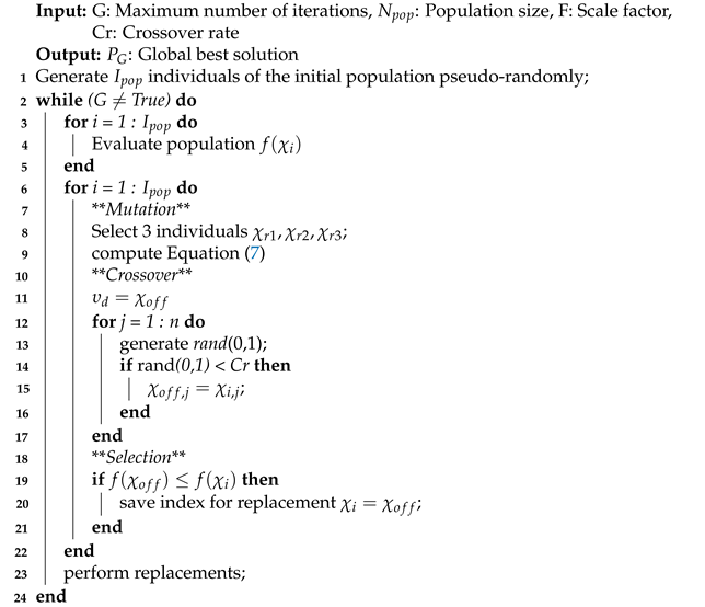
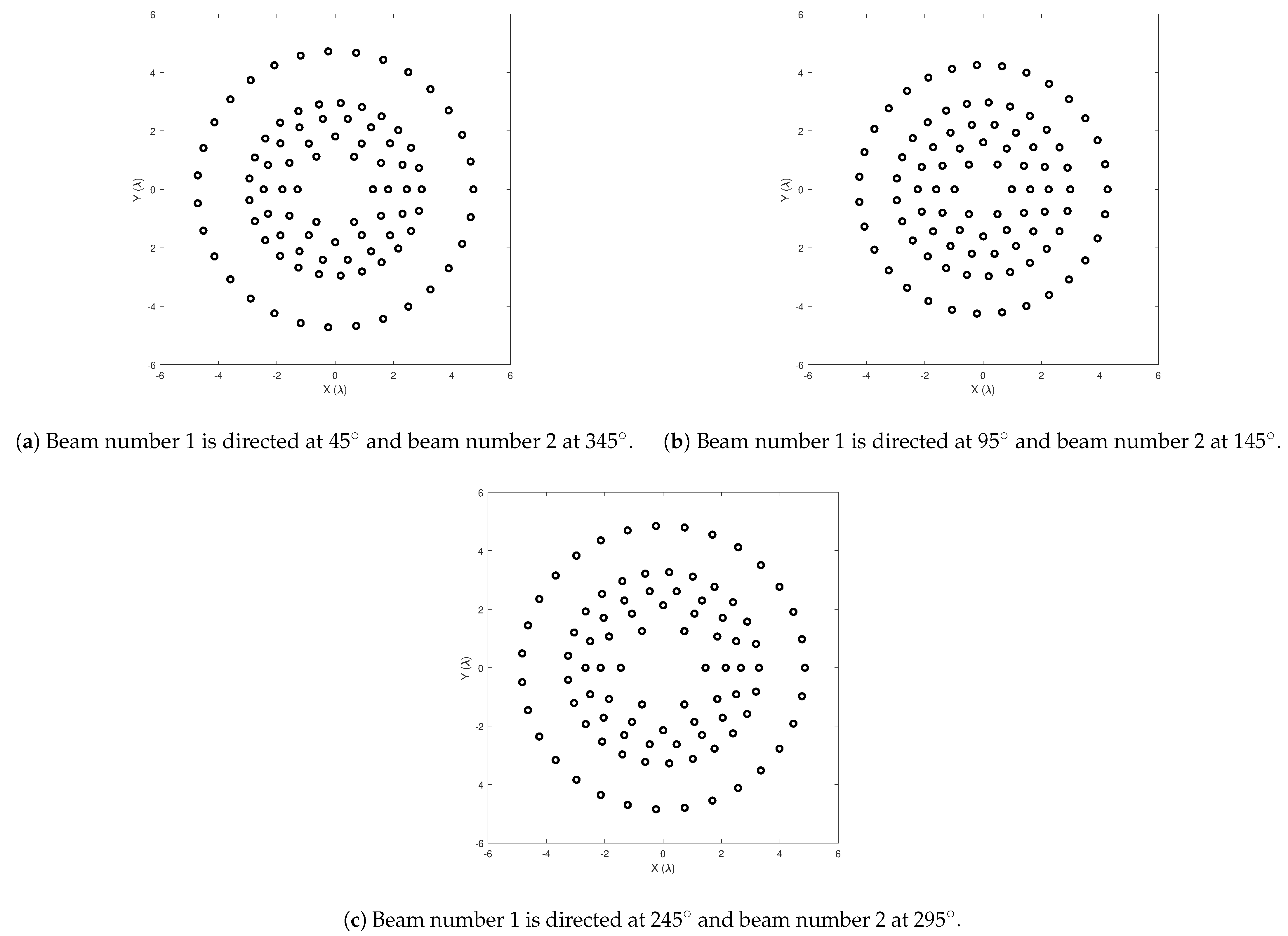
3. Numerical Results

In this section, the simulation setup is described alongside the numerical results obtained from the two-beam C-BFN configuration for applications in ACRAs. One main objective under this scenario is to estimate the dual-beam pattern generated by the antenna system (i.e., the beamforming network and the non-uniform antenna array), as well as the performance in a comparative study with a uniform layout scenario in order to compare the results. Following this, we made a comparison with the periodic antenna element distribution using the proposed array feeding network and taking the worst solutions from the aperiodic array. Thus, we evaluate the feasible improvements of non-uniform over the uniform aperture on a CCRA fed by a coherent network with steering and multi-beam capabilities. Additionally, we focused on this from an optimization synthesis problem point of view. The complete multi-beam system is optimized under a fair simulation setup with multiple trials by a global optimizer. The intention behind this consists of, using the obtained behavior of the dual-beam radiation patterns analyzed, showing and exhibiting the complexity reduction and performance improvements of using a two-beam coherent feed system with an ACRA.
Figure 3 illustrates the general representation of the antenna setup utilized. The system shows a CCRA integrated by non-uniform spaced rings. Specifically, without loss of generality, this diagram represents an ACRA constituted by radiant elements (92 in total) located within five different circular rings ( N r = 5 ). The number of radiant elements inside each circular ring in the array is constituted, respectively, by [ N 1 , N 2 , N 3 , N 4 , N 5 ] = [ 6 , 12 , 18 , 25 , 31 ] . This radiant element distribution corresponds to N e = 2 π r n / d min | r n = n λ / 2 . In the numerical examples, in order to attenuate any achievable mutual coupling interaction among antenna elements in the array, the spacing between adjacent radiant elements in each circular ring is set at a minimum of d = 0.5 λ and each circular ring is set to be located by the same minimum distance of 0.5 λ with isophoric feeding (a single excitation level) and r 1 0.5 λ . As depicted in the bottom part of Figure 3, the feeding subsystem is a C-BFN based on Q blocks of one layer, which in total integrates the complete coherent network subsystem. In this considered configuration, the Q required C-BFN blocks per ring is equal to the number of circular rings N r , i.e., one C-BFN block for every circular ring within the aperiodic array. In this case, the designed configuration for feeding the aperiodic concentric array is constituted by five C-BFN blocks. For the particular case of this proposal, the (N) output ports of each block are interconnected straight to a radiant element in every circular ring, as shown in Figure 3. Furthermore, at the ends of each C-BFN block, the indices denote the amount of output port signals (top of the individual C-BFN blocks) and the input port signals (bottom part of every C-BFN block). In addition, the proposed C-BFN allows for controlling a couple of independent beams simultaneously in the alternation of the feeding ports in each block, as depicted in the lower part of Figure 3. Thus, the number of beams or signals applied is represented by the indices at the feeding ports, i.e. for the conformation of one of the two beams, each index number belongs to a group of complex inputs.
For the numerical experiments, the DE algorithm was programmed as well as used to optimize the aperiodic antenna system as well as the feeding network. The evolutionary algorithm is set up to initialize with a population of 120 individuals, a crossover rate CR = 0.9 , a factor of mutation fixed in F = 0.5 , and a maximum number of generations/iterations set in G max = 1000 . A random selection, one difference vector, and binomial crossover (DE/rand/1/bin) comprise the DE scheme utilized to optimize the multi-beam radiation pattern. The global stochastic algorithm was run in 20 independent trials for every dual-beam pattern. For this case, the directions of maximum radiation correspond to a slice of the total multi-beam pattern for values of φ ( φ -cutting patterns), where the optimized dual-beam array factors are predominately a function of the θ angle.
Figure 4 depicts the performance of the normalized radiation patterns for the two-beam configuration under study (Figure 3) explained in detail in this same section. In these numeric examples, the target of maximum radiation in this multi-beam scenario is steered towards the azimuth plane and directed at 45°, 95°, and 245° for beam number 1. The beam number 2 is set in 345°, 145°, and 295°. The optimization process utilized to improve the radius of every ring r = r 1 , r 2 , , r 5 on each dual-beam example allows us to obtain and demonstrate a satisfactory performance regarding isolation level and directivity. Concerning the near-optimal ring spacings (radii), we found that the optimization process in these multi-beam cases achieves the following: [ 1.29 λ , 1.81 λ , 2.45 λ , 2.96 λ , 4.73 λ ] for Figure 4a, [ 0.98 λ , 1.61 λ , 2.24 λ , 2.98 λ , 4.26 λ ] for Figure 4b, and [ 1.45 λ , 2.14 λ , 2.66 λ , 3.28 λ , 4.85 λ ] for Figure 4c, and the aperiodic apertures are illustrated in Figure 5.
Furthermore, Table 1 presents the precise numerical values of sidelobe level and directivity retrieved and depicted in each numeric example from Figure 4 with the proposed C-BFN configuration. This table condenses the information from the worst numerical values of SLL and D achieved through the aperiodic aperture via C-BFN on the multi-beam scenario for each numeric example and contrasts the results of the previously mentioned parameters with a uniform aperture (Uniform) with a equivalent coherent feeding network. In addition, Table 1 collects the mean outcomes of the improvement obtained through the aperiodic aperture employing the proposed feeding subsystem on each beam for all of the optimized examples. In each numerical example, the aperiodic layout is straightforwardly set out in comparison with the equivalent uniform layout.
Additionally from Table 1, we can observe that the performance obtained by the worst case of the normalized two-beam patterns generated from the proposed coherent beamforming network outperforms the case of a multiple radiation patterns under the condition of an uniform concentric ring array while using the same feeding system. The general performance shows that a C-BFN configured on a non-uniformly ring-spaced concentric ring array notoriously improves in identical conditions to an uniformly ring-spaced concentric ring array fed by the similar coherent feeding system, in terms of sidelobe level and directivity. The improvement in the shown examples is approximately to −5.6 dB of the sidelobe level and 3.0 dB of the directivity for beam number 1 and −2.5 and 1.3 dB for the same parameters for beam number 2. The improvements (expected values) for each beam are presented in Table 1.
As was demonstrated, the uniform circular concentric geometry fed by a C-BFN maintains the usual nature of circular antenna arrays, retaining inherent high directivity while registering high sidelobe levels over the range of interest. In particular, our proposed two-beam C-BFN configuration that feeds an ACRA characterized by subsets of alternated inputs on each C-BFN block in every ring achieves and retains outstanding numerical values of directivity, i.e., an average performance enhancement between 2.5 and 3.5 dB for beam number 1 and 0.9 and 1.9 for beam number 2 (under equal and fair conditions when running the optimization process). Conversely, all the nonequal layout multi-beam experiments (based on Opt. r ) with the selected coherent system reach higher numerical results of sidelobe level, improving the uniform antenna array, with a performance improvement between −4.7 and −6.2 dB for beam number 1 and −2.2 and −3.0 dB for beam number 2 on average. Furthermore, in this dual-beam configuration, every main beam is shaped and steered to any predefined location utilizing approximately 50% of the input ports (47 input ports for beam number 1 and 45 input ports for beam number 2) for this specific case regarding the total number of radiators ( N = 92 ).
Based on the comparative analysis with respect to the dual-beam ACRAs summarized in Table 1. The experimental results prove and confirm that the beamforming network configuration proposal in addition to an ACRA has enhanced performance on each beam compared to a uniform concentric ring array with an equal feeding system regarding the directivity and sidelobe level. Although a predefined direction of maximum radiation is set for each beam in the numerical experiments, the proposed coherent network configuration can generate and scan every beam to any direction of interest beneath the field of view, with a directivity and isolation level with small fluctuations along the azimuthal plane. To establish the maximum performance and for an unbiased analysis in terms of the antenna design trade-off (D and SLL), including inherent complexity reduction in the network and multi-beam capability, the improvement of a sparseness optimization on the antenna layout has been avoided. Moreover, the optimized circular rings in Figure 5 are considered to be distanced by at least a separation of λ / 2 plus an additional distance ( 0 Δ λ 1.5 λ ) among the rings. The novel resulting optimized non-uniform layouts for the multi-beam scenario show a singular comportment where the last and first rings have the biggest radius and with element density in the radial direction; this specific nature is also found in regular non-uniform circular concentric rings and is associated with a low sidelobe amplitude taper.
The designed two-beam feeding system found on C-BFN for ACRA benefits from its operational behavior, with improved features over the conventional circular concentric aperture in a phased array with direct feeding. Its clear benefits include sharing paths coherently (i.e., mechanism of coherent coupling), allowing multi-beam features, and also reducing control signal ports. In the configuration proposed in this paper, the dual-beam is scanned and shaped approximately with half of the input ports, i.e., a clear reduction of 50 % , only requiring half of the input ports to control each beam compared to the conventional case.
This novel two-beam configuration approach in the proposed feeding system is not exclusive for aperiodic CCRAs. In fact, a variety of C-BFN setup configurations can be designed by properly modifying the layers or the input/output ports based on the number of beams and the overall performance. Thus, this proposed dual-beam antenna system found on C-BFN with a non-uniform circular concentric aperture is a candidate for different antenna applications considering its isophoric feeding and reduced complexity, as well as its multi-beam shaping performance along with the scanning range.

4. Conclusions

This paper introduced a new dual-beam antenna system for a non-uniform circular concentric ring aperture based on a coherent beamforming network, with scanning and multi-beam shaping capabilities. The global performance of two-beam normalized power patterns, generated by the designed coherent network configuration in an aperiodic and periodic circular concentric ring layout, was contrasted and analyzed. The numerical experiments based on antenna synthesis demonstrate and validate that the designed beamforming network comprises a dual-beam with steering and shaping properties, taking advantage of the layout’s aperiodicity, coherent behavior, and isophoric feeding levels, reducing the antenna system’s complexity. In the proposed feeding system configuration based on intercalated input signals grouped on C-BFN blocks per ring, numerical results present substantially lower sidelobe levels ( 17.53 SLL 22.11 for beam 1 and 16.92 SLL 20.61 on average) and improved directivity values ( 17.95 D 19.33 for beam 1 and 16.47 D 18.73 for beam 2 on average), showing a significant reduction in the number of control signals (about 50%), i.e., each beam on the two-beam configuration is controlled and scanned with half of input ports, in contrast with the usual feeding system, which requires one feeding input for each output port. A dual-beam coherent network with an aperiodic concentric ring array surpasses its uniform counterpart by up to −6.1 and 3.5 dB on average for the sidelobe level and directivity per beam, respectively. Further studies will explore this antenna system further by using full-wave electromagnetic analysis.

Author Contributions

Conceptualization, A.A.; methodology, A.A. and E.S.-N.; software, A.A. and D.H.C.; validation, A.A., E.S.-N., U.P.-R., M.C.-J., F.R.C.-S. and D.H.C.; formal analysis, A.A., E.S.-N. and D.H.C.; investigation, A.A.; writing—original draft preparation, A.A., E.S.-N. and U.P.-R.; writing—review and editing, A.A., E.S.-N., M.C.-J., F.R.C.-S. and D.H.C.; visualization, A.A., U.P.-R. and M.C.-J.; supervision, A.A., E.S.-N. and D.H.C.; project administration, A.A., and E.S.-N. All authors have read and agreed to the published version of the manuscript.

Funding

This research work was partially funded by the Mexican National Council for Science and Technology (CONACYT) with the project Catedras (No. 872) and the Program for Professors’ Development (PRODEP) from the Federal Mexican Government.

Data Availability Statement

The data supporting this research article are available upon request to the corresponding author.

Conflicts of Interest

The authors declare that there is no conflict of interests regarding the publication of this manuscript.

References

  1. Blake, J.; Nygren, E.; Schennum, G. Beamforming networks for spacecraft antennas. In 1984 Antennas and Propagation Society International Symposium; IEEE: Piscataway, NJ, USA, 1984; Volume 22, pp. 158–161. [Google Scholar] [CrossRef]
  2. Anguera, J.; Andújar, A.; Jayasinghe, J. High-Directivity Microstrip Patch Antennas Based on TModd-0 Modes. IEEE Antennas Wirel. Propag. Lett. 2020, 19, 39–43. [Google Scholar] [CrossRef]
  3. Laue, H.E.A.; du Plessis, W.P. Numerical Optimization of Compressive Array Feed Networks. IEEE Trans. Antennas Propag. 2018, 66, 3432–3440. [Google Scholar] [CrossRef] [Green Version]
  4. Dorrah, A.H.; Eleftheriades, G.V. Peripherally Excited Phased Array Architecture for Beam Steering with Reduced Number of Active Elements. IEEE Trans. Antennas Propag. 2020, 68, 1249–1260. [Google Scholar] [CrossRef]
  5. Lin, C.-C.; Tzuang, C.-K.C. A dual-beam micro-CPW leaky-mode antenna. IEEE Trans. Antennas Propag. 2000, 48, 310–316. [Google Scholar] [CrossRef]
  6. Floc’h, J.M.; El Sayed Ahmad, A.; Kokar, Y. Dual-Beam Antenna Design for Autonomous Sensor Network Applications. Int. J. Antennas Propag. 2012, 2012, 289681. [Google Scholar] [CrossRef]
  7. Deng, C.; Yu, W.; Lv, X. All-metallic dual-beam antenna with a low profile. In Proceedings of the 2017 IEEE International Symposium on Antennas and Propagation, and USNC/URSI National Radio Science Meeting, San Diego, CA, USA, 9–14 July 2017; pp. 2121–2122. [Google Scholar] [CrossRef]
  8. Hakimi, A.M.; Oraizi, H.; Keivaan, A.; Amini, A. Wideband Vertically Polarized Dual-Beam Antenna Using Modulated Metasurfaces. In Proceedings of the 14th European Conference on Antennas and Propagation (EuCAP 2020), Copenhagen, Denmark, 15–20 March 2020; pp. 4–8. [Google Scholar] [CrossRef]
  9. Xi, R.; Ang, S.; Porter, K.; Li, L. Generation of dual-beam orbital angular momentum vortex beam using transmit arrays. In Proceedings of the 2019 IEEE International Symposium on Antennas and Propagation, and USNC/URSI Radio Science Meeting, Atlanta, GA, USA, 7–12 July 2019; pp. 993–994. [Google Scholar] [CrossRef]
  10. Verevkin, A.P.; Kirillov, V.V.; Munina, I.V.; Turalchuk, P.A. Dual-beam Transmitarray for High Capacity Wireless Communication Systems. In Proceedings of the 2020 IEEE Conference of Russian Young Researchers in Electrical and Electronic Engineering (EIConRus 2020), Moscow, Russia, 27–30 January 2020; pp. 84–86. [Google Scholar] [CrossRef]
  11. Nikfalazar, M.; Sazegar, M.; Mehmood, A.; Wiens, A.; Friederich, A.; Maune, H.; Binder, J.R.; Jakoby, R. Two-Dimensional Beam-Steering Phased-Array Antenna With Compact Tunable Phase Shifter Based on BST Thick Films. IEEE Antennas Wirel. Propag. Lett. 2017, 16, 585–588. [Google Scholar] [CrossRef]
  12. Liu, S.; Chen, Q. Dual-Beam Gain-Reconfigurable Antennas Using A Shared Reflectarray Aperture. In Proceedings of the 2019 International Symposium on Antennas and Propagation (ISAP)-Proceedings, Xi’an, China, 27–30 October 2019; pp. 1–3. [Google Scholar]
  13. Chou, H.; Jian, H. Numerical design of dual-beam open-end waveguide antenna array for the angular diversity at millimeter waves. In Proceedings of the 2016 Asia-Pacific International Symposium on Electromagnetic Compatibility (APEMC 2016), Shenzhen, China, 17–21 May 2016; Volume 1, pp. 118–120. [Google Scholar] [CrossRef]
  14. Kodgirwar, V.P.; Deosarkar, S.B.; Joshi, K.R. Design of Dual-Band Beam Switching Array for Adaptive Antenna Applications Using Hybrid Directional Coupler and E-Shape Slot Radiator. Wirel. Pers. Commun. 2020, 113, 423–437. [Google Scholar] [CrossRef]
  15. Betancourt, D.; del Rio Bocio, C. A Novel Methodology to Feed Phased Array Antennas. IEEE Trans. Antennas Propag. 2007, 55, 2489–2494. [Google Scholar] [CrossRef]
  16. Betancourt, D.; del Rio, C. 3 by 3 phased array controlled by only three phase shifters. In Proceedings of the 2006 First European Conference on Antennas and Propagation, Nice, France, 6–10 November 2006; pp. 1–3. [Google Scholar] [CrossRef]
  17. Panduro, M.A.; del Rio-Bocio, C. Design of beam-forming networks using CORPS and evolutionary optimization. AEU Int. J. Electron. Commun. 2009, 63, 353–365. [Google Scholar] [CrossRef]
  18. Arce, A.; Covarrubias, D.H.; Panduro, M.A. Design of a multiple-beam forming network using CORPS optimized for cellular systems. AEU Int. J. Electron. Commun. 2012, 66, 349–356. [Google Scholar] [CrossRef]
  19. Saliani, N.; Bemani, M.; Kazemi, H. Modified CORPS beamforming network with null-steering capability. IET Microw. Antennas Propag. 2019, 13, 1208–1213. [Google Scholar] [CrossRef]
  20. Arce, A.; Stevens-Navarro, E.; Cardenas-Juarez, M.; Pineda-Rico, U.; Covarrubias, D.H. A Coherent Multiple Beamforming Network for a Non-uniform Circular Antenna Array. Radioengineering 2019, 27, 74–83. [Google Scholar] [CrossRef]
  21. Arce, A.; Stevens-Navarro, E.; Cardenas-Juarez, M.; Pineda-Rico, U.; Simon, J.; Panduro, M.A. Design and Optimization of a Coherent Beamforming Network for an Aperiodic Concentric Ring Array. Int. J. Antennas Propag. 2019, 2019, 1–10. [Google Scholar] [CrossRef] [Green Version]
  22. Balanis, C.A. Antenna Theory: Analysis and Design, 3rd ed.; John Wiley & Sons: New York, NY, USA, 2005. [Google Scholar]
  23. Haupt, R.L. Optimized element spacing for low sidelobe concentric ring arrays. IEEE Trans. Antennas Propag. 2008, 56, 266–268. [Google Scholar] [CrossRef]
  24. Salas-Sanchez, A.A.; Fondevila-Gomez, J.; Rodriguez-Gonzalez, J.A.; Ares-Pena, F.J. Parametric Synthesis of Well-Scanning Isophoric Pencil Beams. IEEE Trans. Antennas Propag. 2017, 65, 1422–1427. [Google Scholar] [CrossRef]
  25. Bencivenni, C.; Ivashina, M.V.; Maaskant, R. Reconfigurable aperiodic array synthesis by Compressive Sensing. In Proceedings of the 2016 10th European Conference on Antennas and Propagation (EuCAP), Davos, Switzerland, 10–15 April 2016; pp. 1–3. [Google Scholar] [CrossRef] [Green Version]
  26. Fonseca, N.J.G. Design and implementation of a closed cylindrical BFN-fed circular array antenna for multiple-beam coverage in Azimuth. IEEE Trans. Antennas Propag. 2012, 60, 863–869. [Google Scholar] [CrossRef]
  27. Rotman, R.; Tur, M.; Yaron, L. True Time Delay in Phased Arrays. Proc. IEEE 2016, 104, 504–518. [Google Scholar] [CrossRef]
  28. Zaker, R.; Abdipour, A.; Tavakoli, A. Full-wave simulation, design and implementation of a new combination of antenna array feed network integrated in low profile microstrip technology. Analog. Integr. Circuits Signal Process. 2014, 80, 507–517. [Google Scholar] [CrossRef]
  29. Ferrando, N.; Fonseca, N.J.G. Investigations on the efficiency of array fed coherently radiating periodic structure beam forming networks. IEEE Trans. Antennas Propag. 2011, 59, 493–502. [Google Scholar] [CrossRef]
  30. Deb, A.; Roy, J.S.; Gupta, B. A Differential Evolution Performance Comparison: Comparing How Various Differential Evolution Algorithms Perform in Designing Microstrip Antennas and Arrays. IEEE Antennas Propag. Mag. 2018, 60, 51–61. [Google Scholar] [CrossRef]
  31. Eltaeib, T.; Mahmood, A. Differential evolution: A survey and analysis. Appl. Sci. 2018, 8, 1945. [Google Scholar] [CrossRef] [Green Version]
  32. Opara, K.R.; Arabas, J. Differential Evolution: A survey of theoretical analyses. Swarm Evol. Comput. 2019, 44, 546–558. [Google Scholar] [CrossRef]
  33. Neri, F.; Tirronen, V. Recent advances in differential evolution: A survey and experimental analysis. Artif. Intell. Rev. 2010, 33, 61–106. [Google Scholar] [CrossRef]
Figure 1. General layout of a concentric circular ring array (CCRA).
Applsci 11 01111 g001
Figure 2. Typical coherent beamforming network (C-BFN) topology based on unit cells for power division/combination, illustrating the shared aperture at the output.
Applsci 11 01111 g002
Figure 3. Schematic of the dual-beam array feed network subsystem and the aperiodic antenna array aperture.
Applsci 11 01111 g003
Figure 4. Normalized patterns in dB generated by the two-beam feeding network with a non-uniform CCRA optimized using differential evolution.
Applsci 11 01111 g004
Figure 5. Aperiodic layouts of the concentric ring arrays in the numeric examples while optimizing antenna rings ( r ).
Applsci 11 01111 g005
Table 1. Results of the conducted experiments and mean values of the non-uniformity improvement on the proposed antenna system in terms of sidelobe level (SLL) and D.
Antenna SystemNumber ofMain Beam ACRA + CBFN Improvement
(Array + CBFN)BeamDirectionSLL [dB]D [dB]SLL [dB]D [dB]
Uniform1 and 2 0 φ 0 360 −14.4915.35
Multi−beam (Opt. r )145°−19.6717.89−6.23.2
95°−17.4017.78−4.72.5
245°−20.4618.88−6.13.5
2345°−17.5916.12−3.00.9
145°−16.7416.65−2.21.3
295°−16.8617.27−2.31.9
Publisher’s Note: MDPI stays neutral with regard to jurisdictional claims in published maps and institutional affiliations.

