Article

Extension of the Equivalent Material Concept to Compressive Loading: Combination with LEFM Criteria for Fracture Prediction of Keyhole Notched Polymeric Samples

1
Fracture Research Laboratory, Faculty of New Science and Technologies, University of Tehran, Tehran 1439957131, Iran
2
Laboratory of Materials Science and Engineering (LADICIM), University of Cantabria, E.T.S. de Ingenieros de Caminos, Canales y Puertos, Av/Los Castros 44, 39005 Santander, Spain
3
Department of Mechanical and Industrial Engineering, Norwegian University of Science and Technology (NTNU), Richard Birkelands vei 2b, 7491 Trondheim, Norway
*
Authors to whom correspondence should be addressed.
Appl. Sci. 2021, 11(9), 4138; https://doi.org/10.3390/app11094138
Submission received: 6 April 2021 / Revised: 27 April 2021 / Accepted: 29 April 2021 / Published: 30 April 2021
(This article belongs to the Topic Metallurgical and Materials Engineering)

Abstract

:

Featured Application

This work provides a comprehensive methodology to derive the fracture loads of polymeric structural components containing keyhole notches and subjected to compressive loading.

Abstract

This work analyzes, both theoretically and experimentally, the fracture process of square specimens weakened by keyhole notches and subjected to compressive stresses. Two materials are covered: general-purpose polystyrene (GPPS) and poly(methyl methacrylate) (PMMA). Firstly, the load-carrying capacity (LCC) of the specimens is determined experimentally. Then, by using the equivalent material concept (EMC) for compressive conditions coupled with the maximum tangential stress (MTS) and the mean stress (MS) criteria, the LCC of the notched specimens is predicted. The results show that by using the approach proposed in the present investigation, not only can the critical loads in the keyhole notched polymeric specimens be precisely predicted, but also the corresponding compressive critical stress of the two mentioned polymers can be successfully estimated.

1. Introduction

When defects such as U-shaped notches accumulate damage at their tip, leading to the appearance of short cracks, a common repairing method consists of drilling a hole with a radius (generally) equal to the crack length. Obviously, this repairing alternative will result in the creation of a keyhole notch if the crack length is greater than the original notch tip radius [1]. In addition, materials with brittle or quasi-brittle behavior like most polymers require extra attention, because fracture in these materials usually occurs abruptly. In what follows, some studies on brittle fracture of notched components are briefly described.
Regarding brittle fracture in notched components under pure mode I, pure mode II, or mixed-mode I/II loading conditions, a number of papers have been published employing various failure criteria (e.g., [1,2,3,4,5,6,7,8,9,10,11,12,13,14,15,16]), generally aiming to obtain the corresponding load-carrying capacity (LCC).
At the same time, polymers have shown a wide range of applications due to their broad spectrum of properties [17], and since polymeric engineering components usually contain notches with different shapes and sizes, understanding their fracture behavior by means of notch fracture mechanics (NFM) is crucial. In [12,13,18,19], the fracture behaviors of poly(methyl methacrylate) (PMMA) and general-purpose polystyrene (GPPS) have been studied in the presence of different notches and under various loading conditions. The fracture behavior of other notched or cracked brittle polymeric components has also been investigated in [20,21,22].
The earliest research works on the brittle fracture of notched components under compressive stresses were undertaken before the year 2000 (e.g., [23,24,25,26,27,28,29]). Numerous fracture experiments were performed in [30] on rectangular graphite specimens containing V-notches with end holes (VO-notches), with the goal of recording the fracture loads of the specimens. In [30], also, the results of the experiments were successfully estimated by means of the strain energy density (SED) criterion. In 2014, by employing the point stress (PS) and mean stress (MS) criteria, Torabi and Ayatollahi [31] successfully estimated the fracture loads reported in [30]. Ayatollahi et al. [32] suggested two new test specimens made of PMMA for fracture testing under compression, and they used stress-based fracture criteria in order to predict the fracture loads. Other investigations regarding the brittle fracture of specimens made of PMMA and GPPS polymers weakened by round-tip V-notches, keyhole notches, and VO-notches under mixed-mode I/II loading with negative mode I contributions have been reported in [33,34], respectively.
Recently, Bura et al. [35] conducted purely compressive fracture tests on PMMA specimens weakened by notches with different shapes and sizes, and using a high-speed camera, they analyzed the strain evolution during the fracture processes. Their valuable work has provided an effective tool for understanding the mechanisms of failure, and the types of crack nucleation and propagation from the notch edge caused by the local compressive stresses.
In 2012, with the aim of simplifying the prediction of fractures in notched/cracked ductile members with nonlinear behavior, a novel concept, called the equivalent material concept (EMC), was proposed by Torabi [36]. This concept has been successfully used together with traditional linear elastic fracture mechanics (LEFM) criteria for the estimation of the nonlinear failure of components containing different kinds of stress concentrations [36,37,38,39,40,41,42].
For the first time, the experimental and theoretical fracture assessments of keyhole notched specimens made of the general-purpose polystyrene (GPPS) and poly(methyl methacrylate) (PMMA) under negative mode I loading are carried out in the present research. By utilizing two well-known brittle fracture criteria, the maximum tangential stress (MTS) criterion and the mean stress (MS) criterion, the load-carrying capacity (LCC) of the mentioned specimens is theoretically predicted. Then, these analytical outcomes are compared with experimental results. It is shown that both fracture criteria can precisely foresee the LCCs of the notched specimens. After that, in order to calculate the critical stresses and predict the LCCs of the polymeric specimens without any need for complex and time-consuming calibration, the equivalent material concept (EMC) under compressive loading is employed and coupled with the MTS and the MS criteria. Finally, it is shown that the EMC-MTS and the EMC-MS coupled criteria are fully capable of predicting the experimental results.

2. Materials and Methods

2.1. Compression and Fracture Tests

Two different well-known quasi-brittle polymeric materials were chosen to fabricate the keyhole notched specimens: PMMA and GPPS. These two polymers exhibit brittle behavior with minor plastic deformations at room temperature during tensile loading. However, when the standard un-notched PMMA and GPPS specimens are tested under compression, significant plastic deformations are developed. One reason for the larger plastic deformation under compression is that the Poisson’s ratio under compression is significantly different from the ratio under tension, leading to a change of the cross-sectional area under compression that may be considerably larger than that observed under tension. Consequently, the growth rate of the cross-sectional area under compression becomes considerably greater than the reduction rate of such area under tension.
The determination of the compressive properties of the polymers chosen in this study has been performed following ASTM D695-10 [43]. Accordingly, the geometry of the specimens is a block of 12.7 × 12.7 × 25.4 mm3 (½ × ½ × 1 in3). The compression tests, three per material, were performed under displacement-control conditions. The load was recorded by the load-cell, and by using the initial cross-sectional area, the engineering stresses were computed. Concerning the displacements, the travel of the plates was assumed to be the same as that occurring in the specimens. Consequently, the engineering strains were calculated by dividing the recorded displacements by the initial length of the specimen. This procedure is accurate within the elastic regime (used for the estimation of the elastic moduli) and does not affect the calculation of the ultimate tensile strength. Beyond the linear-elastic behavior, and especially beyond the peak point, where friction becomes significant and barreling starts happening, accurate measurement of the strains would require the use of an extensometer.
Concerning the fracture tests under negative mode I (compression) loading, the geometry of the corresponding specimens is shown in Figure 1. It can be observed that it is a rectangular specimen weakened by a keyhole, with the hole radii varying from 0.5 mm up to 4 mm, and the thickness being 8 mm.
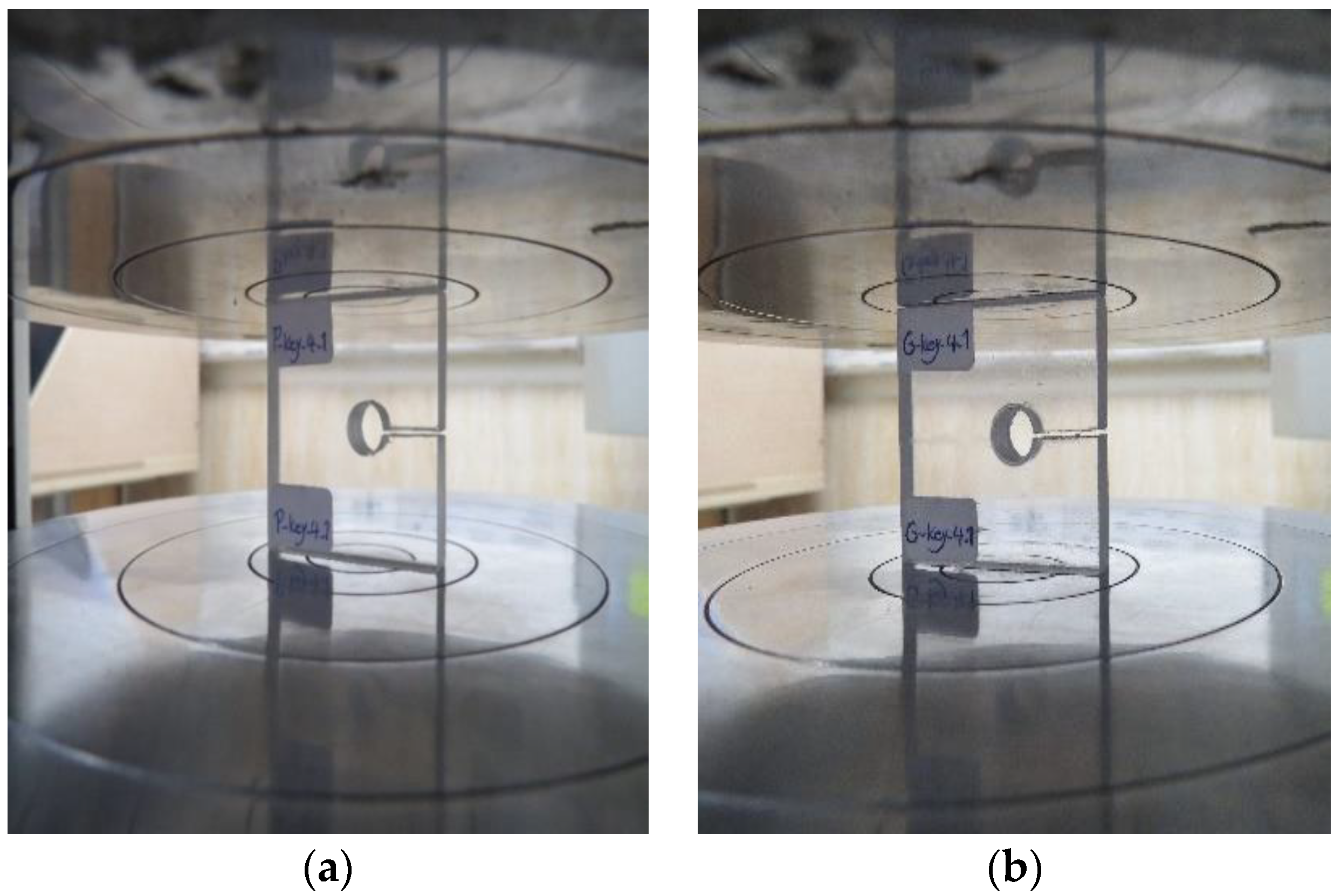
The specimens were machined from PMMA and GPPS plates with the same thickness. In order to prevent the appearance of residual stresses around keyhole notches during the production process, a two-dimensional water-jet cutting machine was used. The total number of specimens is 24, combining the two materials, the four notch radii and three tests per combination of material and notch radius. Figure 2 shows two of the specimens.
The displacement rate of the test machine is set as equal to 0.5 mm/min to provide quasi-static loading conditions.

2.2. The Equivalent Material Concept under Compressive Loading

The equivalent material concept (EMC) was proposed by Torabi [36] in order to avoid the complexities of elastoplastic analyses when dealing with ductile fracture under tensile loading. Below, this concept is presented in its original form. Then, it is extended to compressive loading, with the aim of obtaining the critical stress of the material being analyzed. This is of practical importance, given that it can be utilized as an essential input in the context of the LEFM criteria when estimating the LCCs of the keyhole notched PMMA and GPPS specimens tested under compression.
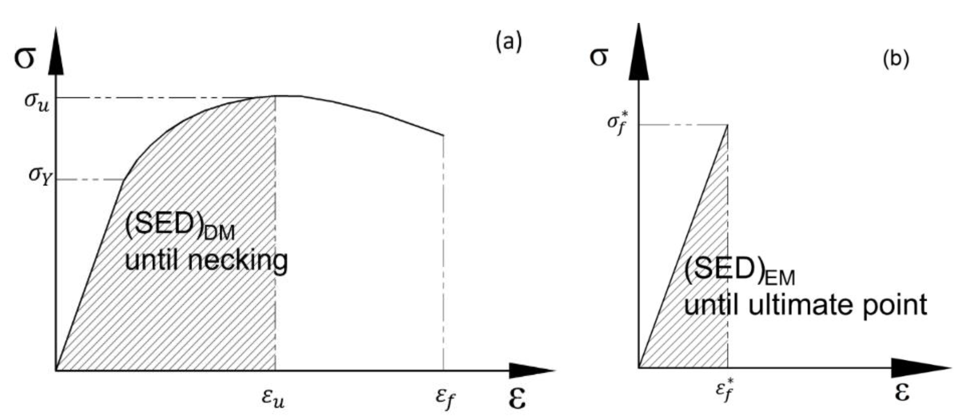
The EMC equates a ductile material having elastic-plastic behavior with a virtual brittle material showing linear elastic behavior until final fracture [36], and having the same elastic modulus and fracture toughness as the real elastoplastic material, but with a different tensile strength. For obtaining the tensile strength of the virtual brittle material, the two materials are assumed to have the same values of strain energy density (SED) until the ultimate point. This means that the shaded areas in Figure 3 must be equal.
Now, given that both materials have the same elastic modulus, and according to [36], by equalizing the expressions of the SEDs of the ductile and the equivalent materials, the following equation can be obtained:
( S E D ) D M = ( S E D ) E M = σ f * 2 2 E
where E and σf* are the elastic modulus and the tensile strength of the virtual brittle material, respectively. In accordance with Equation (1), the tensile strength of the virtual material follows Equation (2):
σ f * = 2 E ( S E D ) D M
Therefore, by entering the SED of the ductile material (i.e., (SED)DM, see Figure 3a) into Equation (2), the tensile strength of the virtual brittle material can be easily calculated.
Although the EMC was originally formulated for tensile loading conditions, it can also be used under compressive loading conditions. Since in compressive loading both stress and strain have negative values, the sign of (SED)DM remains positive, but the equivalent compressive strength will become negative. Hence, the compressive strength follows Equation (3):
σ f * = 2 E ( S E D ) D M
With all this, it can be expected that the critical loads of the keyhole notched GPPS and PMMA specimens tested under compression may be estimated by using the resulting values from Equation (3) in various brittle fracture models, such as those briefly outlined in the following sub-section.

2.3. The Maximum Tangential Stress and the Mean Stress Criteria

Regarding the analysis of brittle fracture in keyhole notched specimens under different loading conditions, a broad diversity of failure criteria has been employed in the literature. Herein, two of the most well-known fracture models, namely, the maximum tangential stress (MTS) and the mean stress (MS) criteria, are employed.
Based on [44], the MTS criterion postulates that, in a brittle medium, fracture (or cracking) takes place once the tensile tangential stress at a specific critical distance (rc) reaches the value of the critical stress (σc). In the case of brittle and quasi-brittle materials, this critical stress (σc) is usually considered to be the same as the material ultimate tensile strength (σu) [45]. In addition, according to [45], the critical distance of the material can be calculated by:
r c = 1 2 π ( K I c σ u ) 2
where KIc is the material plane–strain fracture toughness.
Another brittle fracture criterion utilized in the present investigation is the MS criterion. This was first proposed by Wieghardt [46] to estimate brittle fracture in cracked samples. The MS criterion proposes that fracture occurs when the average tensile tangential stress over a particular critical distance (dc) from the notch tip meets the material critical stress (σc). Seweryn [47] suggested Equation (5) for computing the critical distance (dc):
d c = 4 r c = 2 π ( K I c σ u ) 2
When dealing with crack-like defects, under negative mode I loading conditions the crack faces are in contact with each other, so the pre-existing crack does not propagate and instead, the failure of the cracked specimen occurs through different mechanisms. Hence, the parameter KIc becomes physically meaningless and, subsequently, Equations (4) and (5) (rc and dc) seem revoked under such loading conditions. Thus, another approach should be used for the determination of both rc and dc.
In this sense, Ayatollahi et al. [32] proposed a new method based on experimental calibration, successfully estimating the compressive fracture toughness of round-tip V-notched PMMA samples. In this work, a similar calibration process is followed by performing finite element (FE) analyses of the tested specimens for the calculation of the existing compressive tangential stress distributions, from which the critical stress (σc) and the critical distances (rc and dc) may be inferred. Here, it should be noted that the critical stress will thus be obtained by two different methodologies: the direct application of the EMC, and the above-mentioned calibration process.

2.4. Finite Element Analyses

As mentioned above, finite element (FE) stress analyses are needed for completing the calibration of the critical stress and the critical distances and, ultimately, for predicting the LCCs of the keyhole notched polymeric samples studied in this paper. In the present investigation, two-dimensional (2D) plane-stress FE models were created and analyzed by employing commercial code ABAQUS/CAE 6.10 (Dassault Systèmes Simulia Corp., Johnston, RI, USA). As shown in Figure 4, the bottom line of the model is entirely fixed by constraining all its nodes. In addition, in order to conduct the simulation of the loading conditions accurately, the average critical load for each combination of material and notch radius (see experimental results below) was applied to the top line of the specimen model as a uniformly distributed compressive load (see Figure 4).
About 160,000 eight-node plane-stress quadratic elements were used with the medial axis mesh algorithm. Since the stress gradient is significant near the notch tip, refined elements with the size of 0.02 mm were defined in this region (see Figure 5). The mesh pattern used in the FE analyses is based on the authors’ large experience in the numerical analysis of notched components. The analysis of numerous two-dimensional (2D) notched specimens by the authors (e.g., [31,32,33,34]) has demonstrated that optimal results, with excellent convergence, are obtained when the size of the meshes at the notch tip is about 0.02 mm. Here, it is important to notice that unlike in general FE analyses performed in the context of solid mechanics, for which the entire mesh pattern may contribute to the mesh-sensitivity analysis, in the field of notch fracture mechanics (NFM), the mesh pattern far from the notch tip does not affect the numerical results.
It should be highlighted that, based on the experimental observations, in which obvious contact occurred between the horizontal edges of the key-hole notches, frictionless contact was defined between such edges.

3. Results and Discussion

3.1. Compression and Fracture Tests

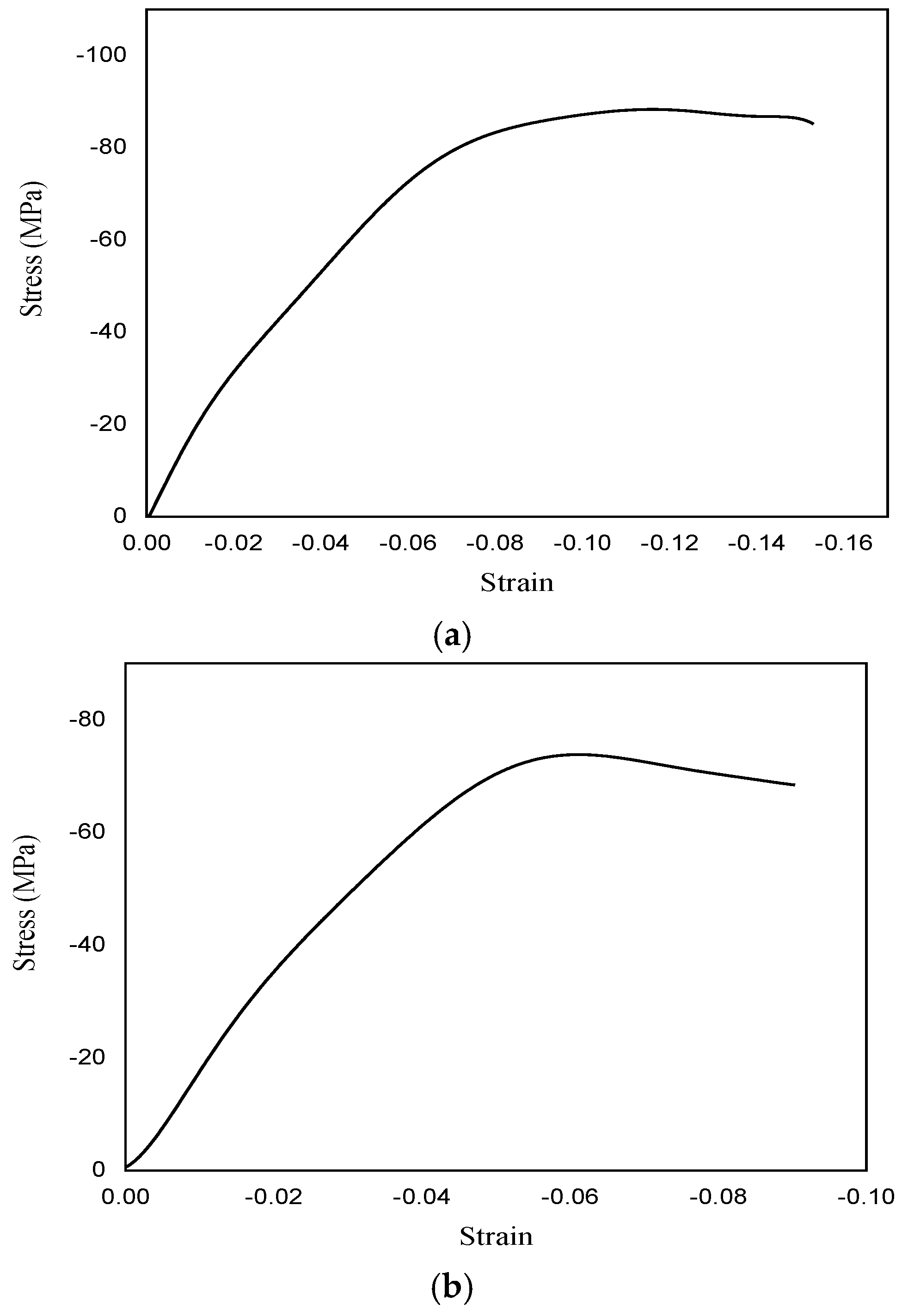
Table 1 shows the main compressive properties for both polymeric materials, whereas Figure 6 shows examples of the obtained compressive engineering stress–strain curves. The results show a clear non-linear behavior in the compression curves of the two materials, although PMMA is significantly more non-linear (ductile) than GPPS.
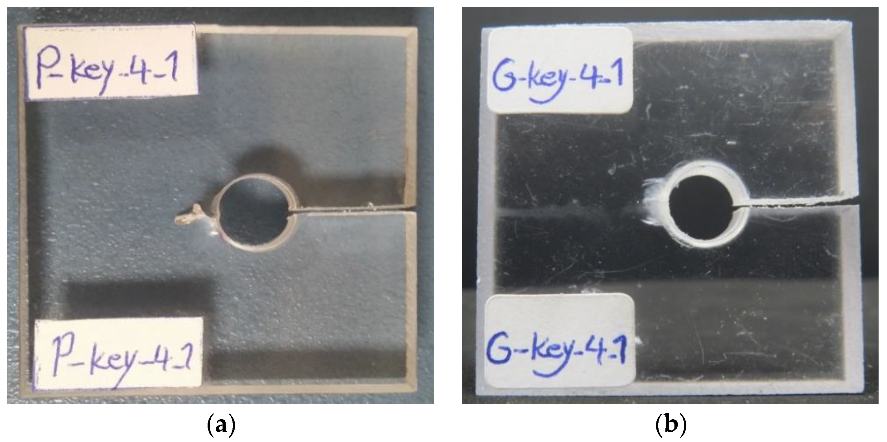
Table 2 shows the LCCs of the different tested fracture specimens, which can be interpreted as the peak points of the corresponding load-displacement curves. In the table, the notch tip radius, the three repetitions, and the average critical load are indicated by ρ, Pi (i = 1, 2, 3), and Pavg, respectively. Figure 7 shows two of the keyhole notched specimens after testing. It can be observed that at the neighborhood of the blunt tip of the keyhole notch under compressive loading an evident damage zone is created, from which a crack initiates and propagates abruptly. This phenomenon is in accordance with the findings reported in [32]. Herein, it is worth mentioning that such an event would not happen in the tensile mode I loading (also known as the notch opening mode), under which only a single crack initiates from the notch tip and grows promptly.
The results show a significantly larger LCC in the case of PMMA, which is more than double the LCC of GPPS for all the different notch radii considered in this work. Moreover, the two polymers show a clear notch effect, developing progressively larger LCCs when the notch radius increases. The notch effect is more significant in GPPS, for which the LCC increases by 31.2% when comparing the results for 0.5 mm and 4 mm radii, this increase being 20.5% in the case of PMMA.
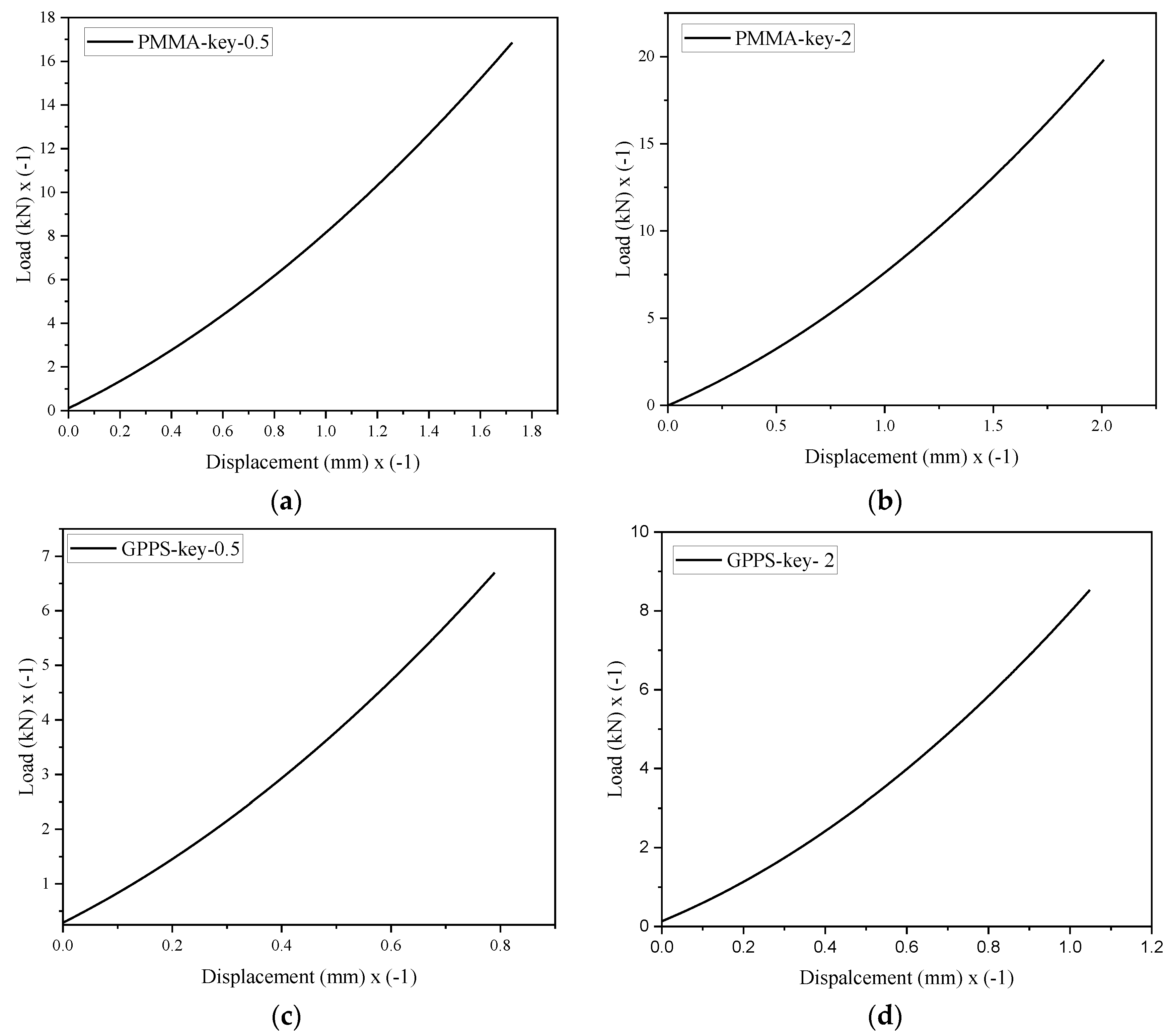
Figure 8 gathers some of the load-displacement curves obtained in tests of the key-hole notched specimens under compression. It is interesting to note that the shape of the curves is different from that observed in fracture tests of notched components either under tension or compression. Most probably, this is because of the contact between the key-hole notch parallel faces during loading.

3.2. Calibration of Critical Stress and Critical Distances

The distribution of linear-elastic stresses around keyhole notches was numerically obtained by executing the above-described FE analyses. The compressive stress distributions around some of the keyhole notches are represented in Figure 9. It is evident in the figure that, in agreement with the experimental observations, at the critical conditions, the horizontal edges of the key-hole notches contact each other, with the area of contact depending directly on the notch tip radius, the magnitude of the applied load, and the material being analyzed. Interestingly, Figure 9c illustrates a full contact between the notch edges for the GPPS specimen weakened by a keyhole notch of 4 mm tip radius.
As mentioned in Section 2, under compressive loading conditions, the fracture toughness KIc becomes physically meaningless. Since the critical distances of PMMA and GPPS are necessary for the theoretical predictions derived from both the MTS and the MS criteria, and since they cannot be computed from Equations (4) and (5), an alternative experimental calibration must be performed. In what follows, one alternative approach is applied, which can be considered as an extension of the theory of critical distances (TCD) [48] from the positive mode I loading to negative mode I loading.
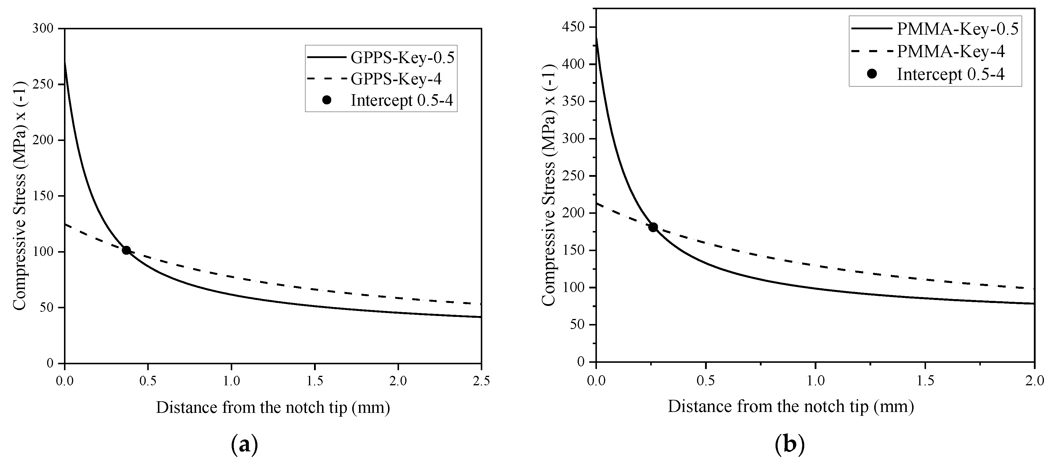
The approach starts with the FE models of the specimens weakened by keyhole notches, with notch tip radii of 0.5 and 4 mm, and subjected to the mean values of the experimentally recorded fracture loads. These two specimens have the maximum and the minimum stress concentrations, respectively, of all the specimens being analyzed. After that, on the bisector line of the keyhole notch, and starting from the notch tip, a straight path is established. Regarding the MTS criterion, the variations of the compressive stresses along the distance from the notch tip are obtained for both PMMA and GPPS specimens. This results in having two stress–distance curves for each material (one for the notch tip radius of 0.5 mm, and the other for the 4 mm notch radius). Then, these stress–distance curves are drawn in a single graph, as shown in Figure 10. The coordinates of the point at which the curves intersect each other are considered to be the critical stress σc (y component) and the critical distance rc (x component). The resulting values are reported in Table 3.
Concerning the MS criterion, the procedure is very similar, but the stress–distance curves are drawn based on the mean compressive stresses computed by the integral method. First, several distances are chosen along the bisector line of the notch, and the corresponding mean stresses are calculated. Secondly, each distance and its corresponding mean stress are represented by a single point in a mean stress–distance plot, and by connecting these points, a curve is obtained. Again, the obtained curves for 0.5 mm and 4 mm notch tip radii are plotted in a single figure and the intercept point of the two curves is defined as the compressive critical stress σc and the critical distance dc. The mean stress–distance plots for PMMA and GPPS polymers are shown in Figure 11, and the values of the critical stress and critical distance derived from the MS criterion are gathered in Table 3.
By examining Table 3, it can be observed that, for PMMA, dc is very close to 4rc. For GPPS, however, dc is approximately 4.8rc, which is 20% larger than dc = 4rc derived from Equations (4) and (5) in tensile conditions. This issue requires additional investigation in other materials to analyze the relationship between the two critical distances under compressive loading conditions. Moreover, the deviations of the critical stress values derived from the experimental calibrations through the MTS and the MS criteria are about 9% and 16% for PMMA and GPPS, respectively, which are quite acceptable.

3.3. Estimation of Load Carrying Capacity

The LCC of the different keyhole notched specimens with tip radii of 1 mm and 2 mm was performed by using the corresponding FE stress analyses, and applying the MTS and the MS criteria with the values of rc and σc shown above. When considering the MTS criterion, the critical load is reached when the compressive stress at the critical distance rc in front of the notch tip reaches the critical stress σc. When using the MS criterion, the critical load is obtained when the mean value of the compressive stresses over the critical distance dc attains σc. Here it should be noted that, because of the contact between the two parallel edges of the keyhole notches during the loading process, and due to the resulting dependence of the contact area on the load being applied, a trial-and-error procedure is essentially needed to extract the critical loads according to MTS and MS criteria. Normally, when determining the critical load in non-contacting notches analyzed using linear elastic fracture mechanics (LEFM), an arbitrary load is first applied to the notched member and the corresponding stress distribution is obtained around the notch. Then, the arbitrary load is multiplied by a known factor, which is actually the ratio between the critical stress and the normal stress obtained for the arbitrary load at the critical distance (or the average normal stress over the critical distance), to achieve the critical load. In other words, the stress field is simply scaled to obtain the critical condition. This strategy cannot be used in the analyzed keyhole notches, as the resulting contacts impede the scaling procedure. Thus, a trial-and-error process is required: an arbitrary load is first applied to the keyhole notched sample, and the compressive stress at the critical distance rc is computed. Depending on its value, the load is increased or decreased until the stress attains the compressive critical stress of the material. This procedure may continue several times to reach the critical load according to the MTS criterion. An analogous approach is followed for the MS criterion but, this time, determining the mean stress over the critical distance dc.
The theoretical and experimental LCCs, together with their discrepancies for the keyhole notched PMMA and GPPS samples, are gathered in Table 4. The results show that both the MTS and the MS criteria are fully capable of providing accurate predictions of the fracture loads of the keyhole notched polymeric specimens under compressive loading conditions. Note that since the critical stress and the critical distances are derived from the experimental calibration, in which the test data of the keyhole notches with the tip radii 0.5 and 4 mm are included, the discrepancies for the keyhole notch tip radii 0.5 and 4 mm are zero. The discrepancies found for notch radii of 1 mm and 2 mm are lower than 10%, with the estimations being conservative in all cases (i.e., estimated fracture loads below the experimental fracture loads). On this occasion, for both PMMA and GPPS, the MTS criterion is more accurate than the MS criterion.
As shown above, and since the behaviors of the PMMA and GPPS polymers in the standard compression tests are nonlinear, the compressive critical loads of the keyhole notched samples can be computed by the application of the Equivalent Material Concept (EMC). Therefore, the EMC will be employed here to calculate the critical stresses of the two polymers. Subsequently, the EMC (through the resulting critical stresses) will be coupled with the MTS and the MS criteria to predict the critical loads of the keyhole notched polymeric samples. With this aim, it is only necessary to assume that the critical stress σc is equal to the compressive strength of the equivalent linear-elastic material. Thus, for both polymeric materials, the areas under the compressive stress–strain curves, up to the corresponding peak point (see Figure 6), were calculated. After that, these values were substituted into Equation (3). The resulting compressive strengths (σf*) of the equivalent materials are equal to −175.1 and −90.2 MPa for the PMMA and the GPPS, respectively. These critical stress values are appealingly close to those achieved from the experimental calibration. Finally, the estimations of the LCCs were derived from the MTS and the MS criteria and using σf* as σc (EMC-MTS and EMC-MS predictions). The results are reported in Table 5.
In contrast to Table 4, since the values of critical stresses are not obtained from the experimental calibration, the discrepancies for the notch tip radii 0.5 and 4 mm are no longer equal to zero. In addition, for all notch tip radii, the discrepancies are considerably lower, always below 10%. This shows that not only is the EMC capable of estimating the compressive critical stress of the two polymers, but also that both the EMC-MTS and the EMC-MS coupled criteria can outstandingly predict the fracture loads of keyhole notched polymeric specimens under compression loading. Finally, it is worth mentioning that the EMC-MTS criterion has provided conservative predictions of the experimental fracture loads for both PMMA and GPPS, whereas the EMC-MS criterion provided critical load estimations larger than the experimental ones (slightly non-conservative results).
It may be of interest for the reader to know that the authors are currently working on the prediction of the compressive critical loads of notched specimens using a fully analytical approach. This requires determining the critical distances under compression without any experimental calibration.

4. Conclusions

In this work, a set of fracture tests were performed on PMMA and GPPS keyhole notched specimens with various notch tip radii and subjected to compressive loading. The corresponding load-carrying capacity (LCC) of the notched specimens was experimentally obtained. Then, by using the theory of critical distances (TCD), the critical stress and the critical distances of the maximum tangential stress (MTS) and the mean stress (MS) criteria were calibrated by using part of the experimental results and finite element analyses. Additionally, the critical stresses of the two materials were theoretically estimated by employing the equivalent material concept (EMC) under compressive loading.
The results indicated that the critical stresses obtained from the experimental calibration could be successfully estimated by means of the EMC.
Finally, the resulting fracture criteria (MTS, MS, EMC-MTS and EMC-MS) were applied to derive estimations of the fracture loads (or LCCs). It was shown that the four criteria provide highly accurate predictions of the fracture loads of PMMA and GPPS keyhole notched specimens under closing mode loading.

Author Contributions

Conceptualization, A.R.T.; methodology, A.R.T.; software, K.H.; validation, A.R.T., K.H., B.S., S.C. and F.B.; investigation, A.R.T., K.H. and B.S.; writing—original draft preparation, A.R.T. and S.C.; writing—review and editing, A.R.T., K.H., B.S., S.C. and F.B.; project administration, A.R.T. All authors have read and agreed to the published version of the manuscript.

Funding

This research received no external funding.

Institutional Review Board Statement

Not applicable.

Informed Consent Statement

Not applicable.

Data Availability Statement

The data presented in this study are available in the main text of this document.

Conflicts of Interest

The authors declare no conflict of interest.

References

  1. Torabi, A.R.; Abedinasab, S.M. Fracture Study on Key-Hole Notches under Tension: Two Brittle Fracture Criteria and Notch Fracture Toughness Measurement by the Disk Test. Exp. Mech. 2015, 55, 393–401. [Google Scholar] [CrossRef]
  2. Berto, F.; Lazzarin, P.; Gomez, F.J.; Elices, M. Fracture Assessment of U-Notches under Mixed Mode Loading: Two Procedures Based on the Equivalent Local Mode I Concept. Int. J. Fract. 2007, 148, 415–433. [Google Scholar] [CrossRef]
  3. Torabi, A.R.; Pirhadi, E. Stress-Based Criteria for Brittle Fracture in Key-Hole Notches under Mixed Mode Loading. Eur. J. Mech. A Solids 2015, 49, 1–12. [Google Scholar] [CrossRef]
  4. Berto, F.; Lazzarin, P.; Marangon, C. Brittle Fracture of U-Notched Graphite Plates under Mixed Mode Loading. Mater. Des. 2012, 41, 421–432. [Google Scholar] [CrossRef]
  5. Gomez, F.J.; Elices, M.; Berto, F.; Lazzarin, P. Local Strain Energy to Assess the Static Failure of U-Notches in Plates under Mixed Mode Loading. Int. J. Fract. 2007, 145, 29–45. [Google Scholar] [CrossRef]
  6. Berto, F.; Lazzarin, P. A Review of the Volume-Based Strain Energy Density Approach Applied to V-Notches and Welded Structures. Theor. Appl. Fract. Mech. 2009, 52, 183–194. [Google Scholar] [CrossRef]
  7. Chen, D.H.; Ozaki, S. Investigation of Failure Criteria for a Sharp Notch. Int. J. Fract. 2008, 152, 63–74. [Google Scholar] [CrossRef]
  8. Lazzarin, P.; Zambardi, R. A Finite-Volume-Energy Based Approach to Predict the Static and Fatigue Behavior of Components with Sharp V-Shaped Notches. Int. J. Fract. 2001, 112, 275–298. [Google Scholar] [CrossRef]
  9. Ayatollahi, M.R.; Torabi, A.R. Determination of Mode II Fracture Toughness for U-Shaped Notches Using Brazilian Disc Specimen. Int. J. Solids Struct. 2010, 47, 454–465. [Google Scholar] [CrossRef] [Green Version]
  10. Zappalorto, M.; Carraro, P.A. An Efficient Energy-Based Approach for the Numerical Assessment of Mode I NSIFs in Isotropic and Orthotropic Notched Plates. Theor. Appl. Fract. Mech. 2020, 108, 102612. [Google Scholar] [CrossRef]
  11. Gogotsi, G.A. Fracture Toughness of Ceramics and Ceramic Composites. Ceram. Int. 2003, 7, 777–784. [Google Scholar] [CrossRef]
  12. Bura, E.; Seweryn, A. Mode I Fracture in PMMA Specimens with Notches–Experimental and Numerical Studies. Theor. Appl. Fract. Mech. 2018, 97, 140–155. [Google Scholar] [CrossRef]
  13. Gomez, F.J.; Elices, M.; Valiente, A. Cracking in PMMA Containing U-Shaped Notches. Fatigue Fract. Eng. Mater. Struct. 2000, 23, 795–803. [Google Scholar] [CrossRef]
  14. Gomez, F.J.; Guinea, G.V.; Elices, M. Failure Criteria for Linear Elastic Materials with U-Notches. Int. J. Fract. 2006, 141, 99–113. [Google Scholar] [CrossRef]
  15. Torabi, A.R.; Berto, F. Strain Energy Density to Assess Mode II Fracture in U-Notched Disk-Type Graphite Plates. Int. J. Damage Mech. 2014, 23, 917–930. [Google Scholar] [CrossRef]
  16. Kim, J.K.; Cho, S.B. Effect of Second Non-Singular Term of Mode I Near the Tip of a V Notched Crack. Fatigue Fract. Eng. Mater. Struct. 2009, 32, 346–356. [Google Scholar] [CrossRef]
  17. Jin, F.-L.; Li, X.; Park, S.-J. Synthesis and Application of Epoxy Resins: A Review. J. Indust. Eng. Chem. 2015, 29, 1–11. [Google Scholar] [CrossRef]
  18. Aliha, M.R.M.; Bahmani, A.; Akhondi, S. Mixed Mode Fracture Toughness Testing of PMMA with Different Three-Point Bend Type Specimens. Eur. J. Mech. A-Solids 2016, 58, 148–162. [Google Scholar] [CrossRef]
  19. Berto, F.; Campagnolo, A.; Elices, M.; Lazzarin, P. A Synthesis of Polymethylmethacrylate Data from U-Notched Specimens and V-Notches with End Holes by Means of Local Energy. Mater. Des. 2013, 49, 826–833. [Google Scholar] [CrossRef]
  20. Rodriguez, J.; Salazar, A.; Gómez, F.J.; Patel, Y.; Williams, J.G. Fracture of Notched Samples in Epoxy Resin: Experiments and Cohesive Model. Eng. Fract. Mech. 2015, 149, 402–411. [Google Scholar] [CrossRef]
  21. Kanchanomaia, C.; Rattananona, S.; Soni, M. Effects of Loading Rate on Fracture Behavior and Mechanism of Thermoset Epoxy Resin. Polym. Test. 2005, 24, 886–892. [Google Scholar] [CrossRef]
  22. Razavi, S.M.J.; Ayatollahi, M.R.; Esmaeili, E.; da Silva, L.F.M. Mixed-Mode Fracture Response of Metallic Fiber-Reinforced Epoxy Adhesive. Eur. J. Mech. A Solids 2017, 65, 349–359. [Google Scholar] [CrossRef]
  23. Cottrell, B. Brittle Fracture in Compression. Int. J. Fract. Mech. 1972, 8, 195–208. [Google Scholar] [CrossRef]
  24. Hoek, E.; Bieniawski, Z.T. Brittle Fracture Propagation in Rock under Compression. Int. J. Fract. Mech. 1965, 1, 137–155. [Google Scholar] [CrossRef]
  25. Kawakami, H. Notch Sensitivity of Graphite Materials for VHTR. J. Atom. Energy Soc. Jpn. 1985, 27, 357–364. [Google Scholar] [CrossRef] [Green Version]
  26. Wang, E.Z.; Shrive, N.G. Brittle Fracture in Compression: Mechanisms, Models and Criteria. Eng. Fract. Mech. 1995, 52, 1107–1126. [Google Scholar] [CrossRef]
  27. Lajtai, E.Z. Brittle Fracture in Compression. Int. J. Fract. 1974, 10, 525–536. [Google Scholar] [CrossRef]
  28. Lajtai, E.Z.; Carter, B.J.; Ayari, M.L. Criteria for Brittle Fracture in Compression. Eng. Fract. Mech. 1990, 37, 59–74. [Google Scholar] [CrossRef]
  29. Bell, J.F. The Experimental Foundations of Solid Mechanics. In Mechanics of Solids; Truesdell, C., Ed.; Springer Verlag: Berlin/Heidelberg, Germany, 1973. [Google Scholar]
  30. Berto, F.; Lazzarin, P.; Ayatollahi, M.R. Brittle Fracture of Sharp and Blunt V-Notches in Isostatic Graphite under Pure Compression Loading. Carbon 2013, 63, 101–116. [Google Scholar] [CrossRef]
  31. Torabi, A.R.; Ayatollahi, M.R. Compressive Brittle Fracture in V-Notches with End Holes. Eur. J. Mech. A Solids 2014, 45, 32–40. [Google Scholar] [CrossRef]
  32. Ayatollahi, M.R.; Torabi, A.R.; Firoozabadi, M. Theoretical and Experimental Investigation of Brittle Fracture in V-Notched PMMA Specimens under Compressive Loading. Eng. Fract. Mech. 2015, 135, 187–205. [Google Scholar] [CrossRef]
  33. Ayatollahi, M.R.; Torabi, A.R. Investigation of Mixed Mode Brittle Fracture in Rounded-Tip V-Notched Components. Eng. Fract. Mech. 2010, 77, 3087–3104. [Google Scholar] [CrossRef]
  34. Mohammadi, H.; Salavati, H.; Mosaddeghi, M.R.; Yusefi, A.; Berto, F. Local Strain Energy Density to Predict Mixed Mode I + II Fracture in Specimens Made of Functionally Graded Materials Weakened by V-Notches with End Holes. Theor. Appl. Fract. Mech. 2017, 92, 47–58. [Google Scholar] [CrossRef]
  35. Bura, E.; Derpeński, Ł.; Seweryn, A. Fracture in PMMA Notched Specimens under Compression–Experimental Study. Polym. Test. 2019, 77, 105923. [Google Scholar] [CrossRef]
  36. Torabi, A.R. Estimation of Tensile Load-Bearing Capacity of Ductile Metallic Materials Weakened by a V-Notch: The Equivalent Material Concept. Mater. Sci. Eng. A 2012, 536, 249–255. [Google Scholar] [CrossRef]
  37. Majidi, H.R.; Razavi, S.M.J.; Torabi, A.R. Application of EMC-J Criterion to Fracture Prediction of U-Notched Polymeric Specimens with Nonlinear Behaviour. Fatigue Fract. Eng. Mater. Struct. 2019, 42, 352–362. [Google Scholar] [CrossRef]
  38. Torabi, A.R.; Berto, F.; Campagnolo, A. Elastic-Plastic Fracture Analysis of Notched Al 7075-T6 Plates by Means of the Local Energy Combined with the Equivalent Material Concept. Phys. Mesomech. 2016, 19, 204–213. [Google Scholar] [CrossRef]
  39. Majidi, H.R.; Golmakani, M.E.; Torabi, A.R. On Combination of the Equivalent Material Concept and J-Integral Criterion for Ductile Failure Prediction of U-Notches Subjected to Tension. Fatigue Fract. Eng. Mater. Struct. 2018, 41, 1476–1487. [Google Scholar] [CrossRef]
  40. Cicero, S.; Torabi, A.R.; Madrazo, V.; Azizi, P. Prediction of Fracture Loads in PMMA U Notched Specimens Using the Equivalent Material Concept and the Theory of Critical Distances Combined Criterion. Fatigue Fract. Eng. Mater. Struct. 2017, 41, 688–699. [Google Scholar] [CrossRef]
  41. Rahimi, A.S.; Ayatollahi, M.R.; Torabi, A.R. Fracture Study in Notched Ductile Polymeric Plates Subjected to Mixed Mode I/II Loading: Application of Equivalent Material Concept. Eur. J. Mech. A Solids 2018, 70, 37–43. [Google Scholar] [CrossRef]
  42. Rahimi, A.S.; Torabi, A.R.; Ayatollahi, M.R. Ductile Failure Analysis of Blunt V-Notched Epoxy Resin Plates Subjected to Combined Tension-Shear Loading. Polym. Test. 2018, 70, 57–66. [Google Scholar] [CrossRef]
  43. ASTM D695-10. Standard Test Method for Compressive Properties of Rigid Plastics; American Society of Testing and Materials: Philadelphia, PA, USA, 2010. [Google Scholar]
  44. Erdogan, F.; Sih, G.C. On the Crack Extension in Plates under Plane Loading and Transverse Shear. J. Basic Eng. Trans. ASME 1963, 85, 525–527. [Google Scholar] [CrossRef]
  45. Ayatollahi, M.R.; Torabi, A.R.; Rahimi, A.S. Brittle Fracture Assessment of Engineering Components in the Presence of Notches: A Review. Fatigue Fract. Engng. Mater. Struct. 2016, 39, 267–291. [Google Scholar] [CrossRef]
  46. Wieghardt, K. Ueber das Spalten und Zerreissen elastischer Koerper. Z. Math. Phys. 1907, 55, 60–103, (Translated by Rossmanith, H.P. On Splitting and Cracking of Elastic Bodies. Fatigue Fract. Eng. Mater. Struct. 1995, 12, 1371–1405). [Google Scholar]
  47. Seweryn, A. Brittle Fracture Criterion for Structures with Sharp Notches. Eng. Fract. Mech. 1994, 47, 673–681. [Google Scholar] [CrossRef]
  48. Taylor, D. The Theory of Critical Distances. Eng. Fract. Mech. 2008, 75, 1696–1705. [Google Scholar] [CrossRef]
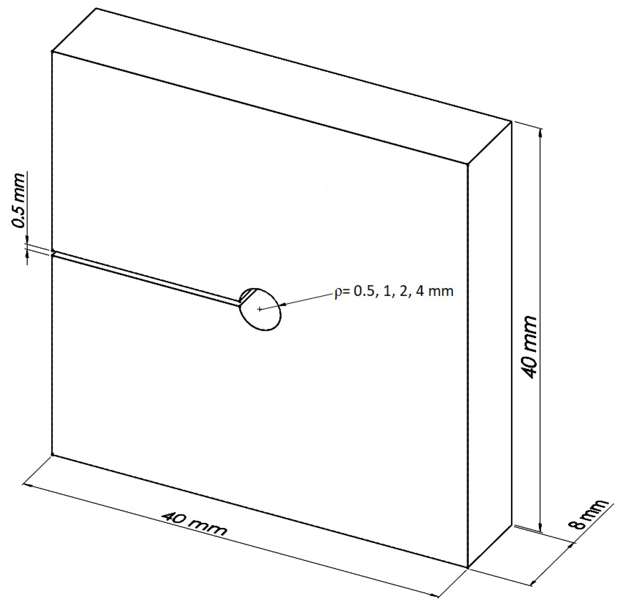
Figure 1. Geometry of the fracture specimens.
Applsci 11 04138 g001
Figure 2. Two keyhole notched specimens shown during the compressive fracture test: (a) PMMA, ρ = 4 mm; (b) GPPS, ρ = 4 mm.
Applsci 11 04138 g002
Figure 3. Schematic of the tensile stress–strain curves: (a) real ductile material (DM); (b) equivalent (brittle) material (EM).
Applsci 11 04138 g003
Figure 4. Loading and boundary conditions for the keyhole notched specimens subjected to compressive loading. BC: boundary conditions.
Applsci 11 04138 g004
Figure 5. Detail of the mesh pattern around the keyhole notch.
Applsci 11 04138 g005
Figure 6. Compressive stress–strain curves for (a) PMMA and (b) GPPS.
Applsci 11 04138 g006
Figure 7. Two of the keyhole notched polymeric specimens after the compressive fracture test: (a) PMMA, ρ = 4 mm; (b) GPPS, ρ = 4 mm.
Applsci 11 04138 g007
Figure 8. Examples of load-displacement curves obtained in key-hole notched specimens under compression: (a) PMMA, ρ = 0.5 mm; (b) PMMA, ρ = 2 mm; (c) GPPS, ρ = 0.5 mm; (d) GPPS, ρ = 2 mm.
Applsci 11 04138 g008
Figure 9. Examples of stress distributions (MPa) for keyhole notches: (a) PMMA, ρ = 0.5 mm, P1 = 16636 N; (b) GPPS, ρ = 0.5 mm, P1 = 7360 N; (c) GPPS, ρ = 4 mm, P2 =9186 N.
Applsci 11 04138 g009
Figure 10. Variations of compressive stress versus the distance from the notch tip: (a) PMMA; (b) GPPS.
Applsci 11 04138 g010
Figure 11. Variations of mean compressive stress versus the distance from the notch tip: (a) PMMA; (b) GPPS.
Applsci 11 04138 g011
Table 1. Main mechanical properties of the two polymers tested under compression.
MaterialE (GPa)Standard Deviation (GPa)σu (MPa)Standard Deviation (MPa)
PMMA1.700.09862.94
GPPS2.140.12682.30
Table 2. Experimental LCCs for the keyhole notched specimens.
Materialρ (mm)P1 (N)P2 (N)P3 (N)Pavg (N)
PMMA0.516,63616,55317,07016,753
117,09317,28817,53717,306
219,03219,20319,32919,188
420,28720,32819,97320,196
GPPS0.57360693372447179
17638766872727526
28941864684488678
49430918696579424
Table 3. Main mechanical properties of the two polymers tested under compression.
Materialrc (mm) MTS Criterionσc (MPa) MTS Criteriondc (mm) MS Criterionσc (MPa) MS Criterion
PMMA0.26−181.10.97−165.2
GPPS0.37−101.41.78−84.7
Table 4. Estimations of LCC derived from the MTS criterion (PMTS) and the MS criterion (PMS), and the discrepancies between estimations and experimental results (Pavg).
Materialρ (mm)Pavg (N)PMTS (N)Discrepancy (%)PMS (N)Discrepancy (%)
PMMA0.516,75316,753016,7530
117,30616,832−2.616,793−2.9
219,18818,549−3.317,614−8.2
420,19620,196020,1960
GPPS0.571797179071790
175267416−1.47203−4.2
286788532−1.67886−9.1
494249424094240
Table 5. Estimations of LCC derived from the EMC-MTS criterion (PEMC-MTS) and the EMC-MS criterion (PEMC-MS), and the discrepancies between estimations and experimental results (Pavg).
Materialρ (mm)Pavg (N)PEMC-MTS (N)Discrepancy (%)PEMC-MS (N)Discrepancy (%)
PMMA0.516,75316,484−1.617,505+4.5
117,30616,982−1.818,214+5.2
219,188187,08−2.520,594+7.3
420,19619,628−2.821,888+8.3
GPPS0.571796919−3.67301+1.7
175267057−6.27681+2.0
286788101−6.69304+7.2
494248669−8.09814+4.2
Publisher’s Note: MDPI stays neutral with regard to jurisdictional claims in published maps and institutional affiliations.