
Development of an Autonomous Driving Smart Wheelchair for the Physically Weak
by
 ,
,
Hye-Yeon Ryu
1 ,
,
Je-Seong Kwon
1,
Jeong-Hak Lim
1,*,
A-Hyeon Kim
2,
Su-Jin Baek
2 and
Jong-Wook Kim
2,* 1
Alpharobotics Co., Ltd., Busan 46028, Korea
2
Department of Electronic Engineering, Dong-A University, Busan 49315, Korea
*
Authors to whom correspondence should be addressed.
Appl. Sci. 2022, 12(1), 377; https://doi.org/10.3390/app12010377
Submission received: 29 November 2021
/
Revised: 22 December 2021
/
Accepted: 29 December 2021
/
Published: 31 December 2021
Abstract
:People who have difficulty moving owing to problems in walking spend their lives assisted by wheelchairs. In the past, research has been conducted regarding the application of various technologies to electric wheelchairs for user convenience. In this study, we evaluated a method of applying an autonomous driving function and developed an autonomous driving function using ROS. An electric wheelchair with a control unit designed to enable autonomous driving was used to test the basic performance of autonomous driving. The effectiveness of the technology was confirmed by comparing the results of autonomous driving with those of manual driving on the same route. It is expected that the evaluation and improvement of the usability and ride quality as well as additional studies will help improve the mobility convenience of physically disabled persons.
1. Introduction
There are various types of disabilities, such as physical disabilities, visual impairments, hearing impairments, and developmental disabilities, and people with disabilities commonly experience difficulties in their daily lives, and they may sometimes not have access to various social rights. Among these rights include the right to move, which is regarded as the most fundamental right. When physical limitations make moving difficult, welfare benefits provided by the government or local governments cannot be used [1]. A wheelchair is a device used by physically challenged people for mobility. However, wheelchair operation is difficult for the elderly, owing to reduced muscle strength and agility. In addition, wheelchair users have a higher probability of upper-limb extremity injuries than non-users [2,3,4]. If an autonomous driving function is applied to an electric wheelchair, the user can move to a desired location without driving.
Herein, a study was conducted on applying an autonomous driving function to a wheelchair, and a chatbot with reinforcement learning was applied to an electric wheelchair so that the physically weak can receive mobility assistance more conveniently. An autonomous driving function was applied to a wheelchair. The function of the wheelchair was confirmed through experiments, such as the minimum turning radius required for driving in a narrow space and chin jumping. In addition, the usefulness of the autonomous driving function when applied to an electric wheelchair by comparing the autonomous driving mode with the manual driving mode was confirmed.
This study comprises six sections. Section 2 discusses the research trends regarding the improvement of electric wheelchairs, and Section 3 presents the reinforcement-learning chatbot that was applied. Section 4 describes the basic specifications of the system applied in this study and the structure used to implement the autonomous driving function. Section 5 discusses the experiments on the basic functions of the implemented system and the experimental results with regard to the effectiveness of the proposed system. Finally, Section 6 presents the conclusions of the study.
2. Related Work
2.1. Conventional Technologies Applied for Convenient Use of Electric Wheelchairs
Many researchers have conducted studies regarding the application of various technologies to use electric wheelchairs more conveniently. For example, some studies have used gaze and voice recognition to control electric wheelchairs. Gusti et al. developed a method for controlling smart wheelchairs using eyelid movements [5], and Nikunj et al. developed a system that enables a person to travel alone by providing freedom of wheelchair operation through voice commands [6]. Kumar et al. also applied a voice recognition module in an electric wheelchair and developed a wheelchair with a voice recognition system that enabled the standing position to be achieved [7].
As an additional device for the convenience of wheelchair users, research regarding a robotic arm applied to a wheelchair is actively being conducted. Caralan et al. proposed a modular mobile robot platform to support moderately and severely disabled people based on an upper extremity robotic exoskeleton mounted on a robotic wheelchair [8]. In addition, Giuffrida et al. proposed a low-cost manipulator that only implements simple operations that can be controlled by three different graphic HMIs [9]. These studies could help to further increase the activity radius of wheelchair users.
Moreover, research has been conducted with the aim to improve the quality of life of people with disabilities by enhancing the convenience of operating electric wheelchairs. Yassine et al. applied a real-time emotion detection system to an electric wheelchair for persons who have difficulty controlling a wheelchair joystick using their hands due to degenerative diseases and trauma. They used an artificial neural network to classify and identify the emotions expressed on the face and used each facial expression of the user as a wheelchair control command. Therefore, even a person not capable of manual control can receive physical assistance using an electric wheelchair [10]. Mohamed et al. conducted a similar study in which they used a brain control system based on EEG signals, head movements, or facial expressions to control the movement of a wheelchair. Therefore, they proved that human thoughts could be used to control an electric wheelchair [11].
Research regarding electric wheelchairs that enable autonomous driving based on artificial intelligence, as in this research, is also being actively pursued. Grewal et al. researched autonomous wheelchairs using an ROS (robot operating system), microcontrollers, LIDAR devices, etc., to ensure the independence and quality of life of the physically vulnerable who have difficulty controlling fine movements [12]. In addition, Subramanian and four others conducted research on wheelchairs that run by looking at where the user wants to go and analyzing their line of sight. After analyzing the line of sight to determine the destination, the system calculates and updates the route to guide the user to their destination [13].
2.2. Conventional Studies on Technologies That Will Apply to the System of This Study
2.2.1. Autonomous Driving Function-Applied Electric Wheelchair
People with disabilities can move with minimal control operations using methods such as autonomous driving. Research regarding autonomous driving function-applied electric wheelchairs has been continually conducted since Manuel et al. developed a wheelchair that facilitated voice commands and obstacle evasion in 1995. The autonomous driving system utilized an infrared sensor, following the wall to identify obstacles [14]. Until the late 2000s, autonomous driving was implemented using one element in the environment, such as the driving line or wall, as a reference point for driving reliability; however, recently, research has been conducted to avoid obstacles and reach a destination without a separate driving line using a light detection and ranging (LiDAR) sensor. Andre et al. developed a system that can transfer inpatients and take inpatients to hospitals using autonomous driving by linking a wheelchair with a hospital information system [15]. However, this system is challenging to apply when moving privately because it requires interlinkage with a central information system. In the case of one-person households with disabilities, a mobility assistance system is necessary because the right to move should be ensured in daily life. We developed a mobility assistance system that can be operated freely by individuals based on these aspects. We developed an electric wheelchair with an autonomous driving function so that one can easily reach a desired place, and we confirmed that it can be practically implemented.
2.2.2. Reinforcement Learning Algorithm for Ensuring the Comfort of Users
When a person uses an electric wheelchair because of difficulty in moving, they spend a lot of time sat in the wheelchair. In this case, the quality of life depends significantly on the wheelchair comfort. Only the user can determine whether their posture is comfortable; however, the comfort and discomfort level of a particular posture can be identified based on the increase/decrease in the use frequency of the user. In this study, we used a reinforcement learning algorithm to learn the preferred postures of users and set optimal postures to improve the quality of life of disabled people using electric wheelchairs.
Reinforcement learning is a learning paradigm for controlling systems to maximize numerical performance measures that represent long-term goals [16]. Since its creation by Richard Bellman in the 1950s, early research was conducted in the 1980s on the link between reinforcement learning and control. In the 1990s, additional analyses of algorithms appeared, and these algorithms were referred to as reinforcement learning [17]. Recently, research has been conducted on deep reinforcement learning. For example, Peter et al. conducted a study on the reproducibility of deep reinforcement learning [18].
3. Chatbot That Applies a Reinforcement Learning Algorithm to Reflect the Wheelchair User’s Moving Preference
If an agent that explores a particular environment recognizes the current state and performs a specific behavior, a reward is obtained from the environment, which can either be positive (reward) or negative (penalty), which is described in Figure 1 The main reinforcement learning algorithm involves finding a policy defined as a series of actions that maximizes future cumulative rewards.
The Markov decision process is a mathematical representation of sequentially and continuously determining actions, wherein a state refers to when the agent observes its circumstance, and an action refers to a movement that the agent can perform in a certain state. When the time is t, the state is , and if an action is performed, the reward function represents the expected value of the reward that will be received. The depreciation rate refers to the rate at which the value of the future reward decreases, and a policy refers to an action that the agent has to perform in all states. The value function refers to the expected value of future rewards that will be received in the current state, as shown in Equation (1):
The Q function is an action value function that shows how good an action is in a certain state, as shown in Equation (2):
where denotes discount rate.
The epsilon-greedy policy takes action for the largest Q function, as shown in Equation (3):
SARSA is an on-policy temporal-difference control, with a structure in which learning is performed by policy iteration, and the value iteration is performed simultaneously. The policy evaluation of a generalized policy iteration (GPI) refers to a temporal-difference prediction using the Q function, and greedy policy improvement refers to a reinforcement learning algorithm that improves the ε-greedy policy.
It consists of two steps: (1) it obtains samples through the ε-greedy policy and (2) uses the obtained samples to update the Q function through the following equation [19]:
where denotes learning rate.
The simulator’s options include the living room, kitchen, bedroom, and bathroom, which are the places where the robot moves inside the house. The robot’s postures include upright, small incline, and large incline, which can be extended to more postures and can be expressed as postures defined by angle values such as 15°, 30°, etc. According to these posture options, the states in Equations (2) and (4) for the posture selection is [“upright,” “small incline,” “large incline”].
The reinforcement-learning-based user command input method developed in this study is as follows:
First, the robot randomly selects one of the three posture options and asks the user whether it is a desired posture before moving to the destination.
If the user answers “no,” the robot selects a different posture and asks again.
If the user answers “yes,” then it is accepted as a reward, and the robot recommends this posture first when moving to the next destination.
The question of whether the current posture is good or bad can be omitted or minimized as follows:
Modifying the program such that the user need not answer each time. That is, an alternative to say “no” only exists when the posture is uncomfortable for the user, which means the recommended posture is default. For more diverse postures, the same reinforcement learning methodology can be applied without problems.
Figure 2 shows an example of command inputs for the implemented reinforcement learning. The parameters of the reinforcement learning were set at . The reward was computed as 1 and −1 when the answers of “yes” and “no”, respectively, were provided.
The user’s usual commands that do not use reinforcement learning are cumbersome to enter each time the robot moves to a destination, and the user’s preferences are not reflected. However, the proposed system uses reinforcement learning to facilitate the automatic setting of the posture tailored to the user’s convenience.
Commanding the robot via a chatbot is more convenient when the user has difficulty in manipulating a joystick or pushing buttons due to blurred eyes or shaking hands. Moreover, chatbots can be programmed to take time into account if a user’s response time can be a measure of abnormality. For example, if the user does not answer within the specified time after the chatbot asks, it can ask again or contact the guardian of the user after several trials of asking.
4. Electric Wheelchair with Autonomous Driving Function
4.1. Electric Wheelchair Used in the Research
To develop an electric wheelchair capable of autonomous driving, a target value was set using items related to indoor driving adhering to the medical device standards published by the Korean Ministry of Food and Drug Safety (see Table 1 [20]). This target is expected to ensure the minimum safety when driving a wheelchair. Because the reference values for the items (Numbers 5 and 6 in Table 1) used to validate the effectiveness of autonomous driving were not included in the standard specifications, we devised them to validate the effectiveness.
4.2. Structural Design for Implementation of Autonomous Driving Function
4.2.1. Design of Control Unit for Autonomous Driving
Autonomous driving technology uses various sensors to collect information regarding the surrounding situation and uses the collected information to enable the user to move to their desired location without the user’s control. The sensors used in this study to implement the autonomous driving function include three units of YDLiDAR G2 and one real sense D435i. Several researchers have conducted studies to implement autonomous driving functions by applying LiDAR sensors [21,22]. Three-dimensional LiDAR has excellent performance but is expensive, and 2D LiDAR is inexpensive, but there is a limitation in that it only recognizes the plane where the LiDAR sensor is installed. We applied 2D LiDAR to spread the product to many people and supplemented the limitations of the 2D version with a depth camera. LiDAR sensors were used at the front (left and right) and the rear center to recognize the 360-degree direction around the robot. Moreover, an RGB-D-based depth camera was added at the front right to recognize the three-dimensional environment that cannot be recognized by the two-dimensional LiDAR, which only recognizes planes of certain heights.
Figure 3 shows a schematic of the control unit of an electric wheelchair for autonomous driving. The signals generated at the input sensors are transmitted to the main controller via a USB hub, and the main controller controls the autonomous driving. The motion controller connected to the main controller receives inputs from the joystick, LCD panel, gyro sensor, etc., and then transmits them to the main controller. The autonomous driving commands sorted through the main controller are delivered to the motion controller, which takes the user to their destination by driving the motor and steering.
4.2.2. Mapping Using SLAM Package
The autonomous driving function used simultaneous localization and mapping (SLAM) and the navigation package of the robot operating system (ROS). SLAM technology was used to create a map of the environment in which the robot was located. The gmapping package [23] was used among many production packages of SLAM, and two-dimensional maps were created from the LiDAR data to enable the robot to collect pose/location data. The odometry values required for SLAM were generated to create a two-dimensional map containing the location data of the robot, and three LiDAR sensors recognized the walls and obstacles when creating 2D maps of the indoor environment required for autonomous driving.
Figure 4 shows the process of creating a map by applying SLAM technology to an actual robot. Figure 4a shows the actual picture of the environment in which the robot creates a map, and Figure 4b shows the map created by the SLAM process using the robot. Figure 4c shows the screen capture of the completed map. They show that the complete map is similar to the actual environment.
4.2.3. Path Generation
A planner is required to generate a driving path of a robot. The planner includes a global path planner and a local path planner. We used the navfn algorithm as a global path planning algorithm, which finds the shortest path from one starting vertex to all other vertices based on the Dijkstra algorithm [24].
An elastic band technique was used to create the local path of the robot [25]. The elastic band technique is a method of selecting velocities to arrive at a destination quickly and reliably while avoiding obstacles that may collide with the robot in the velocity search space of the wheelchair system. Figure 5a shows the path created by the global planner, and Figure 5b shows the elastic band drawn after optimization for local planning. First, the global planner sets a feasible path, which is then optimized through elastic band planning so that the robot can travel following the elastic band. At this time, if there are obstacles not mapped to the map in the path, the path is recalculated and created.
Figure 6 shows the bubbles formed along the path created. A bubble point created on the elastic band is a representative circular range in which the robot does not collide with obstacles on the path. The bubble is small when the obstacles are close and large when they are far away. A collision-free path between the bubble points is created based on the condition that the bubbles are created to avoid collisions on the path through the point superimposition. Finally, the robot moves to the destination by moving the created bubble forward or backward at the bubbles concentrated around the obstacles. The elastic band technique is applied using the move base package, a major component of the navigation stack, to create a path and drive so that the robot can travel to the destination.
Figure 7 shows the move base node structure, which is a major component of the navigation stack. The move base node provides an ROS interface for configuring, executing, and interacting with the robot’s navigation stack. Here, the destination and coordinate values are sent to the global planner to create a route through calculation and send the generated path information to the local planner. After that, the robot receives an odometry topic containing current pose information and calculates the speed to drive to its destination [26].
Figure 8 shows the map and path generated by applying the navigation system to an actual wheelchair robot. Figure 8a–c show that as the robot moves forward, it discovers the obstacles not found in the existing map, creates a new map, and generates a new path in real time to arrive at the destination.
4.2.4. Control Algorithm for Autonomous Driving
Figure 9 shows a flowchart of the algorithm controlled at the main controller for autonomous driving. When the system is switched ON, a drive command is issued to the motor driver. Here, the motor initialization routine is executed to check the speed, speed control, the encoder situation, and whether the motor is required. If there is no problem, the sensors are activated, and initialization is performed. If no problem is found after checking the LiDAR situation and setting the angle, the next step is performed. Subsequently, the destination is entered as an input and the robot starts to drive; it then detects and avoids obstacles in real time. After avoiding the obstacles, when the wheelchair arrives at the destination, it stops; otherwise, the robot drives to the destination again and stops upon reaching the final destination.
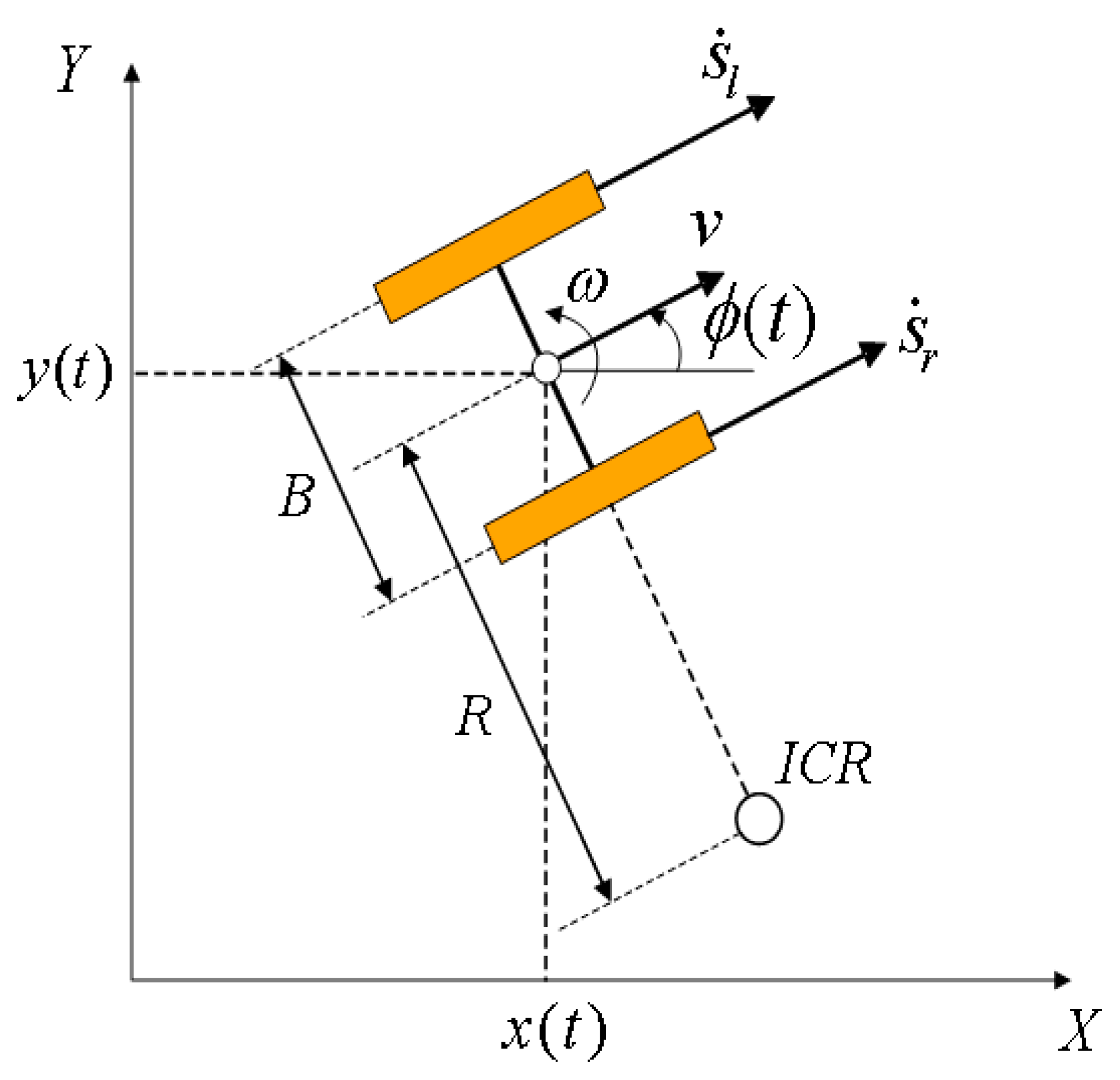
Furthermore, when the robot sends a value to cmd_vel shown in Figure 7, which is the ROS topic that controls the velocity of the robot while driving to the entered destination, it checks whether the angle value on the local path is the same as the current angle value and minimizes the error by the PI control. For explanation of this control algorithm, Figure 10 shows a dynamics model of a mobile robot drawn for calculating the robot’s position vector , which is described with the following trigonometric formula:
where represents the angle of robot direction at the k-th sampling instance with sample time . and denote the linear and angular velocities of robot, respectively, which is calculated with the two encoder values divided by the tick value per meter for each motor. Angular difference is calculated with the following and sent to the general PID control routine.
where denotes the reference angle generated by the local planner.
Acceleration settings are important for wheelchairs to drive safely. By modifying the acceleration parameters of the elastic band technique used in this paper, acceleration was applied so that when the robot stopped, it stopped slowly. However, the jerk restriction parameter was not set separately because it was not included in the elastic band technique parameter.
In this study, we used the ROS Melodic version in the Ubuntu 18.04 OS environment and utilized the eband_local_planner, an open-source package, to implement autonomous driving control.
5. Basic Performance Experiments and Results of the Implemented System
Figure 11 shows appearances of the implemented system manufactured according to the goal performances listed in Table 1, and the experiments were set up and conducted to examine the corresponding items to check the basic performance of the implemented system.
5.1. Minimum Turning Radius of Autonomous Driving
As shown in Figure 12, a circle with a target turning radius of 1300 mm was set up with a tape on the floor. Subsequently, the marker-pen-attached system rotated inside the tape to determine the minimum turning radius of the system. By checking the minimum turning radius of the system using the autonomous driving function, it was confirmed that the turning radius was 1115 mm.
5.2. Obstacle Bump Climbing during Autonomous Driving
The autonomous driving function was used to examine the wheelchair system performance in moving over an obstacle bump. Because the existing goal was to drive by going over an obstacle bump of 15 mm or higher, we prepared different bump heights, 21 mm, 30 mm, 40 mm, and 51 mm, to conduct the experiment. Figure 13 shows photographs of the measurements of the prepared bumps.
The experiment was conducted in the environment shown in Figure 14. We checked whether the system that stopped in front of the obstacle could be driven by going over each obstacle with both the front and rear wheels. Figure 15 shows the experimental results. The robot moved over the obstacle bumps with heights of 21 mm and 30 mm (the total driving distance was 1.9444 m and 2.01 m for the bumps of 21 mm and 30 mm, respectively, confirming that the robot drove more than 1211 mm of the total length of the system). At a height of 40 mm, only the first wheel and mid-wheel went over the bump (total driving distance: 1.005 m), and at a height of 51 mm, none of the wheels went over the bump (total driving distance: 0.01 m).
The obstacle bump jumping experiment was performed 13 times per bump in the autonomous driving condition and 13 times in the manual driving condition. Thirteen experiments were conducted in such a way that, after performing three experiments on each bump, the results were checked, and then ten experiments were performed again to verify the results. The same results were obtained 13 times, confirming that the results were not affected by a specific experiment round or the surrounding environment. Even in the manual driving condition, the same results as those found in the automatic driving condition were confirmed, and through this, it was confirmed that the obstacle bump overcoming function is the performance of the system itself regardless of the driving mode. This can also be proven by the fact that the 40 mm and 51 mm bumps that the system did not cross are lower than the recognition range of the LiDAR sensor and cannot be recognized as an obstacle (LiDAR sensor mounting and detection height: 340 mm from the ground). However, because of the size of the front wheel and the performance of the motor, it was deduced that the highest bump (51 mm) could not be exceeded. In addition, the fact that the bump of 40 mm exceeded the middle was also due to the motor performance. Assuming that the autonomous driving electric wheelchair is used to move to the outside within a short distance, it is necessary to improve the motor performance and change the wheel design so that it can exceed the 50 mm bump.
5.3. Validation of Effectiveness through Comparison between Autonomous and Manual Driving
The evaluation method for the driving performance of service robots is well defined in several standards [27,28]. Among them, we focused on the ratio of the travel path length to the travel path clearance. These two items for checking the driving efficiency were compared by driving in both autonomous and manual driving modes.
To verify the autonomous driving performance, we created a path with obstacles and conducted an experiment for autonomous driving on the path, as shown in Figure 16. There are two obstacles (O) on the path, and the starting point (S) and ending destination point (E) are in a straight line. To ensure the safety of the experiment conductor nearby, the experiment was conducted at the minimum speed of the system.
To validate the effectiveness of the autonomous driving function of the wheelchair, it was driven on the same path using two methods: autonomously (no one was on the wheelchair) and manually (a person sitting in the wheelchair and maneuvering it). Under the premise that accidents, such as hitting an obstacle, did not occur, the efficiency was set to be higher as the robot drove closer to the straight line between the starting and end point, as well as when the robot drove closer to the obstacle while avoiding it. If the driving efficiency of autonomous driving was higher than that of manual driving, then it was inferred that applying an autonomous driving system to a wheelchair is an effective method.
The user who participated in the experiment was a researcher who directly conducted the research and development and became proficient in driving a wheelchair through several trial runs during the development stage. Therefore, it is assumed that there was no performance degradation due to the driver’s inexperience in driving during manual driving. We conducted three experiments each with autonomous driving and manual driving and compared the outcomes with the result of driving closest to the obstacle and the straight path. Under no direct contact with the obstacle, it was deduced that an accident had not occurred.
Figure 17 shows the paths traversed by the wheelchair during autonomous and manual driving. The solid line represents the autonomous driving path, and the dotted line represents the manual driving path. Accidents such as hitting an obstacle did not occur while driving. The farthest positions from the straight line connecting the starting and ending points (ignoring the obstacles) are points A and B, respectively, in Figure 17. Point A, the farthest point from the straight path during autonomous driving, is approximately 60 cm away from the straight path, and point B, the farthest point from the straight path during manual driving, is approximately 124 cm away. Suppose that the maximum distance deviated from the straight path during manual driving is 1, then the ratio of the maximum distance deviated from the straight path during autonomous driving is 0.48, which is smaller than the goal value of 0.7.
We also compared the difference in the detours taken to avoid collisions with obstacles during driving. In Figure 17, point C is the closest point from the center of the obstacle in the detour to avoid obstacles during autonomous driving. The distance from the center of the obstacle is 60 cm. Point D in Figure 17 is the closest point in the detour taken during manual driving, which is 80 cm away from the center of the obstacle. If the minimum distance from the center of the obstacle during manual driving is 1, then the ratio of the minimum distance from the center of the obstacle during autonomous driving is 0.75, which is smaller than the goal value of 0.8.
When we compared the distance deviated from the straight path between the starting and ending points and the maximum distance to avoid from the center of the obstacle, we found that the driving efficiency of autonomous driving was higher. In other words, it was effective to apply the autonomous driving function to an electric wheelchair.
5.4. Curve Driving Test in a Small Indoor Space
The self-driving electric wheelchair developed in this study is intended for indoor driving in hospitals or homes. The narrowest indoor hallway space in a hospital or home is a flat floor space with a width of 1.2 m [29]. Accordingly, the test environment was set as a flat floor space with a width of 1.2 m and a corner section that can be driven frequently when driving indoors.
This experiment was performed 10 times in the autonomous driving mode, and the driving was completed without colliding with a wall in all driving cycles. Figure 18 shows the experimental environment, and Figure 19 shows the screen for the experiment. The results of this experiment confirmed that the developed self-driving electric wheelchair can sufficiently drive in a narrow indoor space and on a curved path.
Because the elastic band technique generates a bubble in the forward direction, it took a lot of time for the robot to reach the target position or it did not arrive well. Among the parameters of the elastic band technique, xy_goal_tolerance is the parameter that sets a distance value to reach a target position. This parameter was adjusted so that the robot could arrive even if the target position was set a little far from actual one. Because of this limitation, the authors are going to develop and add a finishing algorithm to the robot near the target that slightly moves the robot back and aligns the target location to accurately reach the destination.
6. Conclusions
In this study, we developed an electric wheelchair with two artificial intelligence functions to assist physically disabled persons and validated its effectiveness through experiments. The applied functions are a reinforcement learning algorithm for the optimal posture detection of the user and the autonomous driving function for driving convenience. We conducted experiments on the basic performance to verify the effectiveness of the applied functions.
We conducted the minimum turning radius and obstacle bump climbing performance evaluations to check whether the electric wheelchair could turn and overcome obstacles freely during autonomous driving. The minimum turning radius was 557.5 mm compared to the goal of 625 mm, while in the case of going over obstacle bumps, the electric wheelchair went over an obstacle of 3 cm height, satisfying the goal of 1.5 cm. Furthermore, we set up a path with obstacles to check the autonomous driving effectiveness and compared both manual wheelchair driving and autonomous driving along the same path. The results of the path experiments showed that the maximum deviation ratio from the straight path during autonomous driving was 0.48 and the minimum distance ratio from the center of the obstacle was 0.75, confirming the effectiveness of applying the autonomous driving function to the electric wheelchair. In addition, it was confirmed that it can be used in an indoor environment by driving a curved section in a narrow indoor corridor.
The system is still in the prototype stage, and further research will be conducted to upgrade its safety and usability before it is launched in the market. In additional research, (1) usability evaluation and ride comfort are evaluated for actual wheelchair users, and (2) a safer and more convenient electric wheelchair is developed through additional optimization research on the implemented technology. We expect that this will help ensure the mobility and living autonomy of physically disabled people.
Author Contributions
Conceptualization, H.-Y.R., J.-H.L. and J.-W.K.; methodology, J.-W.K.; software, A.-H.K. and S.-J.B.; validation, J.-W.K.; formal analysis, H.-Y.R. and S.-J.B.; investigation, J.-S.K.; resources, J.-S.K.; data curation, H.-Y.R., J.-S.K. and A.-H.K.; writing—original draft preparation, H.-Y.R.; writing—review and editing, J.-W.K.; visualization, H.-Y.R.; supervision, J.-H.L. and J.-W.K.; project administration, J.-H.L.; funding acquisition, J.-H.L. All authors have read and agreed to the published version of the manuscript.
Funding
The Ministry of Trade, Industry and Energy (MOTIE, Korea): Project Number: 20004720.
Informed Consent Statement
Informed consent was obtained from all subjects involved in the study.
Data Availability Statement
Acknowledgments
This work was funded by the Ministry of Trade, Industry, and Energy (MOTIE, Korea). [Project Name: Development of a service robot with variable and close-contact structures for living independence of physically vulnerable people/Project Number: 20004720].
Conflicts of Interest
The authors declare no conflict of interest.
References
- Jihoon, K.; Mingi, Y.; Woontack, W. Optimized Route Navigation System Design for Disabled People who Use Electronic Assistive Devices. In Proceedings of the HCIK (The HCI Society of Korea), Jeju, Korea, 14 February 2019; pp. 381–386. Available online: http://www.hcikorea.org/ (accessed on 1 December 2021).
- Lewis, A.R.; Philips, E.J.; Robertson, W.S.P.; Grimshaw, P.N.; Portus, M. Injury prevention of elite wheelchair racing athletes using simulation approaches. Proceedings 2018, 2, 255. [Google Scholar] [CrossRef] [Green Version]
- Curtis, K.A.; Roach, K.E.; Applegate, E.B.; Amar, T.; Benbow, C.S.; Genecco, T.D.; Gualano, J. Relia-bility and validity of the wheelchair user ’s shoulder pain Index (WUSPI). Spinal Cord 1995, 33, 595–601. [Google Scholar] [CrossRef] [PubMed] [Green Version]
- Cooper, R.A.; Boninger, M.L.; Robertson, R.N. Repetitive strain injury among manual wheelchair users. Team Rehab. Rep. 1998, 9, 35–38. [Google Scholar]
- Pangestu, G.; Utaminingrum, F.; Bachtiar, F. Eye State Recognition Using Multiple Methods for Applied to Control Smart wheelchair. Int. J. Intell. Eng. Syst. 2019, 12, 232–241. [Google Scholar] [CrossRef]
- Nikunj, J.G.; Amutha, J. Voice Controlled Motorized Wheelchair with Real Time Location Monitoring. In Proceedings of the International Conference on Energy, Communication, Data Analytics and Soft Computing, Chennai, India, 1–2 August 2017; pp. 1163–1167. [Google Scholar]
- Kumar, C.R.; Vijayalakshmi, B.; Priyadarshini, S.H.; Sikdar, S.; Bhat, S.N.; Neelam, M. Standing wheelchair with voice recognition system. J. Crit. Rev. 2020, 7, 2042–2047. [Google Scholar]
- Catalan, J.M.; Blanco, A.; Bertomeu-Motos, A.; Garcia-Perez, J.V.; Almonacid, M.; Puerto, R.; Garcia-Aracil, N. A Modular Mobile Robotic Platform to Assist People with Different Degrees of Disability. Appl. Sci. 2021, 11, 7130. [Google Scholar] [CrossRef]
- Giuffrida, G.; Meoni, G.; Fanucci, L. A YOLOv2 Convolutional Neural Neteork-Based Human-Machine Interface for the Control of Assistive Robotic Manipulators. Appl. Sci. 2019, 9, 2243. [Google Scholar] [CrossRef] [Green Version]
- Rabhi, Y.; Mrabet, M.; Fnaiech, F. A facial expression controlled wheelchair for people with disabilities. Comput. Methods Programs Biomed. 2018, 165, 89–105. [Google Scholar] [CrossRef] [PubMed]
- Shahin, M.K.; Tharwat, A.; Gaber, T.; Hassanien, A.E. A Wheelchair Control System Using HumanMachine Interaction: Sin-gle-Modal and Multimodal Approaches. J. Intell. Syst. 2019, 28, 115–132. [Google Scholar] [CrossRef]
- Grewal, H.; Matthews, A.; Tea, R.; George, K. LIDAR-based autonomous wheelchair. In Proceedings of the 2017 IEEE Sensors Applications Symposium (SAS), Glassboro, NJ, USA, 13–15 March 2017. [Google Scholar] [CrossRef]
- Subramanian, M.; Songur, N.; Adjei, D.; Orlov, P.; Faisal, A.A. A.Eye Drive: Gaze-based semo-autonomous wheelchair interface. In Proceedings of the 2019 41se Annual International Conference or the IEEE Engineering in Medicine and Biology Society (EMBC), Berlin, Germany, 23–27 July 2019; pp. 5967–5970. [Google Scholar]
- Mazo, M.; Rodriguez, F.J.; Lázaro, J.L.; Ureña, J.; Garcia, J.C.; Santiso, E.; Revenga, P.; Garcia, J.J. Wheelchair for Physically Disabled People with Voice, Ultrasonic and Infrared Sensor Control. Auton. Robot. 1995, 2, 203–224. [Google Scholar] [CrossRef]
- Baltazar, A.R.; Petry, M.R.; Silva, M.F.; Moreira, A.P. Autonomous wheelchair for patient’s transportation on healthcare institutions. Sn Appl. Sci. 2021, 3, 354. [Google Scholar] [CrossRef] [PubMed]
- Szepesvári, C. Algorithms for reinforcement learning. Synth. Lect. Artif. Intell. Mach. Learn. 2010, 4, 1–103. [Google Scholar] [CrossRef] [Green Version]
- Nathan, L. Gists of Recent Deep RL Algorithms. In towards Data Science. March 2019. Available online: https://towardsdatascience.com/getting-just-the-gist-of-deep-rl-algorithms-dbffbfdf0dec (accessed on 1 December 2021).
- Henderson, P.; Islam, R.; Bachman, P.; Pineau, J.; Precup, D.; Meger, D. Deep Reinforcement Learning that Matters. In Proceedings of the Thirty-Second AAAI Conference on Artificial Intelligence (AAAI-18), Palo Alto, CA, USA, 2–9 February 2021; pp. 3207–3214. [Google Scholar]
- Dang, C.; Baek, S.; Kim, A.; Choi, Y. Development of ROS-based Simulator for a Wheel-chair-typed Service Robot. J. Korean Inst. Intell. Syst. 2020, 30, 214–219. [Google Scholar]
- Korea Ministry of Food and Drug Safety, Medical Device Standard Attachment Table 2 of Medical Device Standards. In-Strument Machine, 1209–1238. 2020. Available online: https://udiportal.mfds.go.kr/standard/P04_03_01?baseStdFlagCode=&stdName=%EC%A0%84%EB%8F%99%ED%9C%A0%EC%B2%B4%EC%96%B4 (accessed on 1 December 2021).
- Rivera, Z.B.; De Simone, M.C.; Guida, D. Unmanned Ground Vehicle Modelling in Gazebo/ROS-Based Environments. Machines 2019, 7, 42. Available online: https://www.mdpi.com/2075-1702/7/2/42 (accessed on 1 December 2021). [CrossRef] [Green Version]
- Fu, Y.; Jha, D.K.; Zhang, Z.; Yuan, Z.; Ray, A. Asok Ray Neural Network-Based Learning from Demonstration of an Autonomous Ground Robot. Machines 2019, 7, 24. Available online: https://www.mdpi.com/2075-1702/7/2/24 (accessed on 1 December 2021). [CrossRef] [Green Version]
- Available online: http://wiki.ros.org/gmapping (accessed on 1 December 2021).
- Available online: http://wiki.ros.org/navfn (accessed on 1 December 2021).
- Quinlan, S.; Khatib, O. Elastic Bands: Connecting Path Planning and Control. In Proceedings of the IEEE International Conference on Robotics and Automation, Atlanta, GA, USA, 2–6 May 1993; Volume 2, pp. 802–807. [Google Scholar]
- Available online: http://wiki.ros.org/move_base (accessed on 1 December 2021).
- ISO 18646-2:2019, Robotics—Performance Criteria and Related Test Methods for Service Robots—Part 2: Navigation, April 2019. Available online: https://www.iso.org/ (accessed on 1 December 2021).
- KS B 7314:2019, Navigation Performance Evaluation Method for Indoor Service Robots–Teaching Assistant Robots, March 2019. Available online: https://www.koros.or.kr/ (accessed on 1 December 2021).
- Infrastructure and Transport Building Safety Team. Rules on Standards for Evacuation and Fire Protection Structures for Buildings, Republic of Korea Ministry of Land, Infrastructure and Transport Ordinance No. 882. In Revision of Other Laws; Republic of Korea Ministry of Land: Seoul, Korea, 2021. [Google Scholar]
Figure 1.
Reinforcement learning.

Figure 2.
Example of the command inputs of the implemented reinforcement learning.

Figure 3.
Schematic of the control unit of the electric wheelchair for autonomous driving.

Figure 4.
Process of creating a map using SLAM. (a) Actual picture, (b) SLAM process, and (c) screen capture of the completed map.
Figure 4.
Process of creating a map using SLAM. (a) Actual picture, (b) SLAM process, and (c) screen capture of the completed map.

Figure 5.
(a) Path created by global planner and (b) elastic band after optimization.

Figure 6.
Bubbles formed along the created path.

Figure 7.
Move base node for the navigation stack.

Figure 8.
Map and path generated by applying the navigation system to the actual wheelchair robot. (a) The obstacles not found in the existing map, (b) creation of a new map, and (c) generation of a new path in real time to arrive at the destination.
Figure 8.
Map and path generated by applying the navigation system to the actual wheelchair robot. (a) The obstacles not found in the existing map, (b) creation of a new map, and (c) generation of a new path in real time to arrive at the destination.

Figure 9.
Flowchart of the algorithm controlled at the main controller for autonomous driving.

Figure 10.
Dynamics variables for a mobile robot (: linear velocity of the left and right wheels, : linear velocity of robot, : angular velocity of robot, ICR: center of rotation, B: distance between wheels).
Figure 10.
Dynamics variables for a mobile robot (: linear velocity of the left and right wheels, : linear velocity of robot, : angular velocity of robot, ICR: center of rotation, B: distance between wheels).

Figure 11.
Appearance of the implemented system.

Figure 12.
Circle with target turning radius.

Figure 13.
Photographs of the measurements of the prepared bumps. (a) 21 mm bump and 30 mm bump, (b) 40 mm bump and 51 mm bump.
Figure 13.
Photographs of the measurements of the prepared bumps. (a) 21 mm bump and 30 mm bump, (b) 40 mm bump and 51 mm bump.

Figure 14.
Experiment set-up.

Figure 15.
Experiment results (blue straight line: distance traveled versus time when crossing a 21 mm obstacle, red dot line: distance traveled versus time when crossing a 30 mm obstacle, green long dot line: distance traveled versus time when crossing a 40 mm obstacle, and purple dash-dotted line: distance traveled versus time when crossing a 50 mm obstacle).

Figure 16.
Experiment for autonomous driving on the path (S: start point, O: obstacle, and E: end point).
Figure 16.
Experiment for autonomous driving on the path (S: start point, O: obstacle, and E: end point).

Figure 17.
Paths that the wheelchair drove during autonomous and manual driving (S: start point, O: obstacle, E: end point, A: the farthest point from the straight path during autonomous driving, B: the farthest point from the straight path during manual driving, C: the closest point from the center of the obstacle in the detour to avoid obstacles during autonomous driving, and D: the closest point from the center of the obstacle in the detour to avoid obstacles during manual driving).

Figure 18.
Curve driving test environment in a narrow indoor corridor.

Figure 19.
Curve driving test driving screen in narrow indoor corridor.


Table 1.
Specifications and numerical goals of electric chair.
| No. | Item | Goal | Avatar |
|---|---|---|---|
| 1 | Maximum length | 1300 mm | 1211.45 mm |
| 2 | Maximum width | 800 mm | 716.5 mm |
| 3 | Minimum turning radius | 1300 mm | 1.115 mm |
| 4 | Obstacle climb | over 15 mm | 30 mm |
| 5 | Ratio of deviation from a straight path during autonomous driving compared to manual driving | less than 0.7 | 0.48 |
| 6 | Ratio of the minimum distance from the center of the obstacle during autonomous driving compared to manual driving | less than 0.8 | 0.75 |
Publisher’s Note: MDPI stays neutral with regard to jurisdictional claims in published maps and institutional affiliations. |
© 2021 by the authors. Licensee MDPI, Basel, Switzerland. This article is an open access article distributed under the terms and conditions of the Creative Commons Attribution (CC BY) license (https://creativecommons.org/licenses/by/4.0/).
Share and Cite
MDPI and ACS Style
Ryu, H.-Y.; Kwon, J.-S.; Lim, J.-H.; Kim, A.-H.; Baek, S.-J.; Kim, J.-W. Development of an Autonomous Driving Smart Wheelchair for the Physically Weak. Appl. Sci. 2022, 12, 377. https://doi.org/10.3390/app12010377
AMA Style
Ryu H-Y, Kwon J-S, Lim J-H, Kim A-H, Baek S-J, Kim J-W. Development of an Autonomous Driving Smart Wheelchair for the Physically Weak. Applied Sciences. 2022; 12(1):377. https://doi.org/10.3390/app12010377
Chicago/Turabian StyleRyu, Hye-Yeon, Je-Seong Kwon, Jeong-Hak Lim, A-Hyeon Kim, Su-Jin Baek, and Jong-Wook Kim. 2022. "Development of an Autonomous Driving Smart Wheelchair for the Physically Weak" Applied Sciences 12, no. 1: 377. https://doi.org/10.3390/app12010377
Note that from the first issue of 2016, this journal uses article numbers instead of page numbers. See further details here.