Article

Virtual Reality Training Application for the Condition-Based Maintenance of Induction Motors

by
David Checa
1,
Juan José Saucedo-Dorantes
2,
Roque Alfredo Osornio-Rios
2,
José Alfonso Antonino-Daviu
3 and
Andrés Bustillo
1,*
1
Department of Computer Engineering, Universidad de Burgos, Avda Cantabria s/n, 09006 Burgos, Spain
2
HSPdigital CA-Mecatronica, Engineering Faculty, Autonomous University of Queretaro San Juan del Rio 76800, Mexico
3
Instituto Tecnológico de la Energía, Universitat Politècnica de València, 46022 Valencia, Spain
*
Author to whom correspondence should be addressed.
Appl. Sci. 2022, 12(1), 414; https://doi.org/10.3390/app12010414
Submission received: 2 November 2021 / Revised: 24 December 2021 / Accepted: 28 December 2021 / Published: 1 January 2022

Abstract

:
The incorporation of new technologies as training methods, such as virtual reality (VR), facilitates instruction when compared to traditional approaches, which have shown strong limitations in their ability to engage young students who have grown up in the smartphone culture of continuous entertainment. Moreover, not all educational centers or organizations are able to incorporate specialized labs or equipment for training and instruction. Using VR applications, it is possible to reproduce training programs with a high rate of similarity to real programs, filling the gap in traditional training. In addition, it reduces unnecessary investment and prevents economic losses, avoiding unnecessary damage to laboratory equipment. The contribution of this work focuses on the development of a VR-based teaching and training application for the condition-based maintenance of induction motors. The novelty of this research relies mainly on the use of natural interactions with the VR environment and the design’s optimization of the VR application in terms of the proposed teaching topics. The application is comprised of two training modules. The first module is focused on the main components of induction motors, the assembly of workbenches and familiarization with induction motor components. The second module employs motor current signature analysis (MCSA) to detect induction motor failures, such as broken rotor bars, misalignments, unbalances, and gradual wear on gear case teeth. Finally, the usability of this VR tool has been validated with both graduate and undergraduate students, assuring the suitability of this tool for: (1) learning basic knowledge and (2) training in practical skills related to the condition-based maintenance of induction motors.

1. Introduction

The incorporation of technologies such as virtual reality (VR) in training has gathered pace in recent years as a result of the great scientific and technological advances within this area. Many advantages can be derived from its use for training, since its application is not limited to a specific area. In fact, a virtual reality application designed for training purposes offers a novel method that facilitates the training task in contrast to traditional training methods. Engineering is no exception, as several applications require laboratories and specialized equipment that are not available to all educational institutions or companies for training and instruction; additionally, VR has become a very useful alternative due to the situation provoked by the SARS-CoV-2 (COVID-19) pandemic that is affecting us at present. The implementation of virtual reality for training purposes provides a very significant cost-effectiveness ratio (highly accurate learning, reduced learning times, and enhanced visualization and comprehension) [1]. It also provides the immediate transfer of behavioral skills in VR environments to the real world. In addition, the potential to develop skills in a risk-free environment is enhanced [2,3,4]. However, access to virtual reality (VR) environments had been excluded from training environments, due to the high cost of VR equipment. Their use over the last 50 years has been limited to military applications and research institutes [5]. Recent advances in VR technology have improved interaction and reduced costs, making them even more attractive for training. Such democratization of technology encourages the development and research of new training applications to provide effective and powerful teaching and training tools.
These advantages offered by VR are partially found in training applications based on 2D interactive systems. On-screen systems are designed to operate with a keyboard and mouse, which is a major constraint in terms of interaction and immersion [6]. Other examples offer a 3D visualization of the environment, also using a screen, which allows them to be more realistic in appearance, usable and immersive, but their interaction is still limited [7,8]. Through these applications that are displayed on screens, the great benefits that virtual reality offers, such as immersion and presence, which are identified as key factors for the enhancement of learning rates [9], are reduced. Likewise, to achieve high learning rates, a second element is required: interactivity. VR applications allow the user to interact with the environment in a natural way, thus enabling the user to learn and train in well-defined areas and tasks. Unlike traditional training environments, where the trainer controls the learning, these VR tools present a trainee-centered approach to training. The user feels in control of an interactive learning process, thus facilitating active and critical learning [10]. Moreover, VR-based simulated environments achieve better learning outcomes compared to those based on 2D interfaces [11].
From a training point of view, thanks to VR environments, the virtual environments of laboratories and test benches can be reproduced with a high rate of similarity to real environments. In addition, it avoids the need for investment and economic losses, as well as unnecessary damage to laboratory equipment and process shutdowns in the industry for capacitation. It also safeguards the integrity of the trainees, so the use of VR environments for teaching and training is of special interest in those specific applications that require experimental practice that may compromise the safety of the users and companies that need to train their technical personnel on specific problems. As a clear example, most industrial processes involve the use of electric rotating machines, such as induction motors. In fact, induction motors represent the most common and essential element in any industrial application [12]. Additionally, induction motors have become part of the everyday equipment used by the entire population, and, for that reason, they are extensively used in a wide range of applications. The most relevant applications are associated with industry, but they are also at home, in remote research applications on land, air, water, and even in space. Thus, the applicability and use of induction motors is so great that more than 90% of applications involved with electrical rotating machines are particularly related to the use of either squirrel-cage or wound rotor induction motors; for industrial applications, most are three-phase squirrel-cage induction motors [13,14]. In this regard, it is estimated that approximately 68% of the energy consumption of industry worldwide is due to induction motors [15], and about 70% of energy consumption is related to induction motor usage in countries such as Brazil, Canada, USA, India and the European Union [16,17]. In addition, its widespread use makes it necessary to understand the basis of its operational conditions as an essential aspect of any industrial training program, as well as in most engineering education curricula.
Additionally, if induction motors are responsible for most of the energy consumption in the industry, the implementation of condition-based maintenance (CBM) programs aims to safeguard their operating condition and their availability. In this regard, there are several condition monitoring approaches that have been proposed over the last few decades to face the occurrence of unexpected faults that may compromise the efficiency of industrial processes and inevitable and excessive energy consumption [13]. Thus, most of the proposed CBM programs have been based on the analysis of different physical magnitudes, where the vibrations, stator current, torque, temperature, and sound remain the most preferable. Even though different signals may be considered, promising results have demonstrated that motor current signature analysis (MCSA) can successfully be used to detect fault occurrences effectively within induction motors [14]. The MCSA is based on the analysis of current signatures by means of different techniques such as fast Fourier transform (FFT), instantaneous power FFT, demodulated current spectrum, wavelet analysis, and Park’s vector approach, among others [15]. Furthermore, the MCSA is one of the most well-known diagnostic approaches in the field of condition assessment applied to induction motors. In fact, it is of proven effectiveness, as malfunctional operating conditions can be detected with this approach, such as broken rotor bars which lead to high temperatures, stator faults due to opening or shorted coils, abnormal connections in the stator winding, bent shafts that produce dynamic eccentricity, and bearing defects and gearbox faults that are coupled to the induction motor under inspection [14,15,16]. The practical implementation of MCSA may represent a complicated task because knowledge related to different areas must be acquired and merged in a practical way. Thus, this drawback is very critical when training new maintenance technicians; it becomes even more critical when data of real experimental test benches and virtual reality tools are not available during the training process.
The contribution of this work focuses on the design and development of a VR-based application for teaching and training in the field of induction motor condition-based maintenance. The novelty of this work relies on:
  • Its ability to fill the existing gap in traditional training thanks to the great advantages offered by state-of-the-art virtual reality devices, such as a great cost-effectiveness, reduced learning times, improved visualization, the ability to understand and develop skills in a risk-free environment as well as the ability to allow the user to interact with the environment in a natural way;
  • The strong link it establishes between the theoretical basis and practice related to the condition-based maintenance of induction motors by means of a VR application as a complementary experimental tool;
  • Its capacity to provide a model for the design and development of an effective VR application, as recent advances in VR technology still show limitations in natural interactions and high development costs.
In addition, this application is available for download and open use.
The application is based on two training modules. The first is focused on knowledge associated with induction motors and its parts, the assembly of workbenches and familiarization with the elements of induction motors. The second module employs MCSA to detect induction motor failures such as broken rotor bars, misalignments, unbalances, and gradual wear on gear case teeth. Indeed, the MCSA module is used to analyze the fault-related frequency components that can be detected over the current spectra estimated by applying fast Fourier transform; additionally, the module aims to show the relationship between the theoretical basis and the practice. Additionally, this VR tool allows us to obtain the experimental raw data from the virtual environment for such failures.
This application is intended to be implemented as a complementary experimental tool within the educational programs for engineering degrees in those courses in which experimental tests are mandatory to train the students, as well as in the training of operators working with induction motors in industry. Likewise, this application represents a practical solution in e-learning situations or when facing critical situations, such as the current SARS-CoV-2 pandemic (COVID-19), which do not allow the implementation of experimental laboratory tests. The design of this tool includes the development and modeling of the 3D virtual environments, the experience, and the interface programming that allows the incorporation of data from external simulation programs or by integrating acquired real-world data. It is designed to be used with virtual reality devices for greater immersion and interactivity, but it can also be used as a desktop tool, thereby increasing its final dissemination.
The remaining sections of this article are organized as follows: in Section 2, the most recent works on immersive virtual reality applications to enhance training in engineering domains are presented. In Section 3, the theoretical underpinnings of the topics in the study are explained, as are the case studies to be addressed. In Section 4, the design and development of the immersive VR training application are described. In Section 5, the validation with final users of the VR-tool application is presented. In Section 6, the results of the validation stage are discussed and compared with the related work. Finally, In Section 6, the main conclusions of this research are highlighted, and future lines of work are established.

2. Related Work

2.1. Virtual Reality Applications

The development of VR-based environments represents a practical and effective solution for training new technicians. Thanks to this technology, a deeper understanding of the operation of the machinery involved in industrial processes can be achieved; in this regard, several investigations have reported the frequent use of non-immersive VR training systems. Certainly, the implementation of training VR tools for the instruction of new technicians is a promising alternative to simulate industrial processes, where the reduction of time, the analysis of different real scenarios without any risk, and the reduction of accidents are the main benefits of VR training in comparison with classical face-to-face training approaches [17]. Thus, there are several works that have reported the use of VR-based tools in the field to train new technicians in real cases referring to different applications. In this sense, a VR training system was reported in [18] to perform both the maintenance and operation of high-voltage overhead power lines where, in a real situation, the technicians are exposed to high-risk procedures and lethal accidents. Similarly, [19] presents the development of a VR-based training system that was designed for industrial operators to perform assembly tasks, in which workers are placed on assembly lines in accordance with their experience; additionally, trainee workers with basic experience can be trained with those assemblies that the expert workers have previously introduced in the system. The general purpose of these applications is to provide practical utility regarding a suitable work-force training for certifying new operators to work under dangerous and complex environments [20,21].
Over the last few years, several research works have explored the use of immersive virtual reality applications for training; thus, in [22], the development and implementation of a training environment using VR to improve technical skills in the maintenance of live-line power distribution networks is presented. This contribution is focused on improving technical skills in maintenance. It provides the trainer with a workforce training system suitable for instructing and certifying operators who will thus be more competent in tasks that involve complex and dangerous environments.
Some examples are also found in virtual training tools for electrical engineering education. In [23], users have the possibility of comparing structural differences between different devices, assembling and disassembling the machines and testing them under extreme conditions. Some examples that present specifically designed solutions for the teaching of induction motors [24,25] are used with head-mounted displays (HMDs) and controllers with only three degrees of freedom (3DOF), such as the Oculus Go, with which users cannot interact with the equipment in a natural way. The use of virtual laboratories in virtual reality stands out against other methods, such as web or video content, due to its ability to provide spatial and embodied interactions that allow hands-on practice for novices. VR has proven itself to be an effective medium to improve knowledge acquisition, retention and self-efficacy, in addition to reducing the error rate when compared to other traditional training methods [26,27].

2.2. Induction Motor Faults by Current Analysis

The extensive and preferred use of the induction motor is due to its robustness, efficiency, and low cost. However, despite the robustness of these electric machines, the unavoidable occurrence of faults is inherent to their working operation. For that reason, in the last decades there have been different attempts to replace the preventive maintenance methods, i.e., the classical practice of preventive maintenance, which is based on the scheduled replacement of the components susceptible to failure, by new maintenance approaces. Preventive maintenance has evolved towards the continuous monitoring and control of certain operating parameters and variables that are observed to determine the right time to intervene and to correct an incipient fault that may produce irreparable damages in the future [13,15]. In this regard, several condition monitoring approaches have been proposed around the world in order to face the unavoidable appearance of faults. Most have been based on the analysis of vibration and temperatures, although the MCSA (motor current signature analysis), which is based on the monitoring of the stator current signal, is still the most preferable and reliable strategy for fault detection in induction motors, as it is capable of detecting faults such as broken rotor bars, misalignments, unbalances, bearing damage and electrical problems in the stator or winding [28].
Different processing techniques may be used to conduct the induction motor assessment; however, MCSA is mainly based on the analysis of those characteristic fault-related frequency components that a particular fault can induce in the stator current signal. For example, in [29], the characteristics of an infinite impulse response (IIR) filter were exploited for detecting the broken rotor bar fault-related frequencies over the estimated stator current spectrum. Likewise, the detection of broken rotor bars in an induction motor was reported in [30] through an analysis of the transient stator current by means of the MUSIC algorithm, which performs an analysis in the time-frequency domain. Thus, MCSA is not limited to a specific domain of analysis. Although complex signal processing is performed by MCSA, the classical approaches are based on the analysis of the effects produced by a specific fault; in this sense, the inspection of different types of misalignments was conducted in [31] by means of MCSA where the diagnosis was achieved though the examination of those fault-related frequency components that appear in the FFT current spectrum. On the other hand, the detection of rotor unbalances was carried out in [32] by performing a bi-spectrum analysis over the stator current signature in an induction motor that was fed by a variable frequency converter. In fact, signal processing techniques that consider complex processes are focused on specific applications where the condition assessment may be complicated, i.e., variable frequency converters which induce additional frequency components in the current consumption during the induction motor operation. Consequently, regardless of the signal processing method that is employed, it has been demonstrated that the application of MCSA may be used as a reliable diagnostic tool capable of detecting the most common failures that affect the working operation of induction motors.

3. Theoretical Basis

3.1. Virtual Reality as a Training Tool

The incorporation of VR-based environments into training or learning is not intended to replace practical sessions with real equipment. However, it can provide complementary benefits such as greater flexibility through exercises to be completed and repeated as many times as necessary. It also offers the possibility of updating and optimizing training methods based on usage, reducing the cost of purchasing physical tools and materials. To create training experiences, it is first necessary to create a virtual environment that is as similar as possible to the real world. The parameters and values of the objects of study are simulated in this environment. Usually, these environments are generated within a game engine. The most common game engines are Unity and Unreal Engine 4 [1]. In this study, the Unreal Engine 4 game engine was chosen, because it is a powerful game engine that produces high-quality interactive virtual reality experiences and provides native support for virtual reality devices. In addition, this software stands out because of its photorealistic capabilities and visual-coding system. It also allows for interfacing with other simulation programs to acquire data in real time and to integrate data from pre-recorded files. Head-mounted displays (HMDs), thanks to the democratization of technology, have become relatively affordable, offering opportunities for implementation in any application scenario [33]. For this development, the HMD HTC Vive Pro Eye was chosen because of its technology that includes a high-quality display and has stable and reliable tracking. It is a virtual reality helmet with six degrees of freedom (6DOF) and is also equipped with 6DOF controllers. However, if this HMD stands out for something, it is for offering an eye-tracking module. Exactly what the user is looking at can be tracked, and detailed performance analyses produced. These features make it ideal for use in training applications [34].
Virtual reality completely changes the way users interact with applications. Immersing users in a virtual world gives them the freedom to experiment and to innovate without any concern about damaging expensive equipment. Thus, in VR, it is possible to experience emergency states and the effects of a misconfiguration and different failures, which are rarely experienced on real equipment, as it can cause damage to the equipment and is often against all health and safety standards. These working conditions also let them work on their own and let them practice outside working hours. In the trainer-user relationship, VR opens a completely different perspective to any classical approach to training. While traditionally the trainee is continuously aware of the trainer’s presence, in immersive VR, this presence can become invisible. Thus, the trainer can adopt three strategies of presence. In the first one, the trainer can control an avatar in the VR environment that interacts with the user, closer to the traditional training model. In the second, the trainer can simply visualize the user’s behavior in real time, providing audio feedback, thus reducing interference in the learning process. In the third, the trainer can avoid any interaction in real time, analyzing a posteriori the data collected from the sensors on the user’s experience. This case is particularly interesting because the user is unaware of the presence of the trainer and behaves in a more natural way, closer to natural behavior in the real environment. However, controllers and gaze tracking sensors collect all their reactions: VR makes it possible to observe how a user behaves with a very high level of detail in a non-invasive way. Finally, it also allows the user to work autonomously and receive immediate feedback on performance [26,35].

3.2. Fault-Related Frequency Components for Detecting Faults in Induction Motors and Gearboxes

The analysis of fault-related frequency components has been considered the fundamental role of MCSA-based condition-monitoring approaches; in this way, it must be highlighted that the most common affectations that may damage an induction motor have characteristic patterns that are inherently induced by their occurrence. Consequently, when an induction motor operates under the influence of broken rotor bars, an affectation is produced that leads to an unbalance of the airgap magnetic flux because the current stops flowing through the broken rotor bar. Several theoretical studies have analyzed this effect and have established the fault-frequency components that facilitate the categorization of these characteristic frequencies according to Equation (1) [28]:
f b = ( 1 ± 2 k s ) f s ,   k = 1 ,   2 ,   3 ,  
where f b is the characteristic fault-related frequency component produced by the occurrence of broken rotor bars, f s is the supply frequency, k is an integer value that can take values of k = 1 ,   2 ,   3 ,   and s is the unit slip that is estimated by Equations (2) and (3):
s = n s n r n s
n s = 60 f s p
where n s is the synchronous speed of the motor, n r is the rotor speed and p is the number of pairs of poles. Thus, frequency harmonics will appear in an estimated current spectrum that can be appreciated as a side band harmonic around the supply frequency, f s : more precisely, first-order side-bands components may appear at (1) when k = 1 and these first-order components are the most significant with which to detect the fault occurrence associated with broken rotor bars. In addition, the two variables, rotational speed and load, affect the amplitude of this fault-related frequency, and the location of the sidebands can be slightly shifted outwards.
On the other hand, the eccentricity problems occur due to an uneven airgap between stator and rotor. The problems associated with eccentricities have also been studied, and characteristic patterns that depict the fault-related frequency components have also been defined. In this regard, in the presence of eccentricity, low-frequency sidebands appear in the stator current spectrum given by Equation (4) [36]:
f e c c = f s [ 1 ± k ( 1 s p ) ] ,   k = 1 ,   2 ,   3 ,  
where f e c c is the fault-related frequency component that depicts the occurrence of eccentricity problems, f s is the supply frequency, s is the unit slip and k is an integer value that can take values of k = 1 ,   2 ,   3 ,   Thus, the dominant frequencies at low frequencies correspond to k = 1 . The existence of these harmonics is due to the interaction between the two most common types of eccentricities: static and dynamic. Theoretically, the harmonics given by (4) will only occur when both eccentricities coexist. Similarly, the fault-related frequency components of the problems produced by misalignments where the induction motor shaft takes part of the coupling have been defined. Thus, the misalignment problem in induction motors may be detected through a spectral analysis following Equation (5) [37]:
f m i s = f s [ 1 ± k ( 1 s p ) ] ,   k = 1 ,   2 ,   3 ,  
This can be rewritten as Equation (6):
f m i s = f s ± f r m
where f m i s is the characteristic fault-related frequency component generated by misalignments, f s is the supply frequency and f r m is the fundamental rotational frequency of the misalignment shaft. Therefore, the misalignment condition may produce spectral modulations that are affected by f r m , and sidebands may appear.
Moreover, over the past decade, MCSA has also been applied as a part of the condition assessment approaches to identify faults within rotating mechanical components such as gearboxes. In this sense, it is possible to perform fault detection in gearboxes by means of MCSA because the gearbox is usually driven by an electrical motor such as an induction motor; thus, it has been demonstrated that gearbox faults may negatively affect the stator current consumption of the induction motor. Specifically, faults in gearboxes lead to modulations of the stator current spectra as a function of the rotational gear speed in which the fault is present; gearbox failure is commonly associated with discrete faults such as chipped or cracked teeth, although little research has been focused on the analysis of gradual faults, such as the uniform wear of the gearing teeth [38]. Regardless of the cases under study, the identification of gearbox faults can be performed by analyzing specific fault-related frequency components, particularly the frequency components described in Equation (6) [39,40]:
f f g = | f s ± k f f p |
where f f g refers to the fault-related frequency component produced by the faulty gear, f s is the supply frequency, f f p is the fundamental frequency of the fault profile related to pinion or wheel rotation frequencies within a one-stage gearbox and k is an integer value that can take values of k = 1 ,   2 ,   3 .

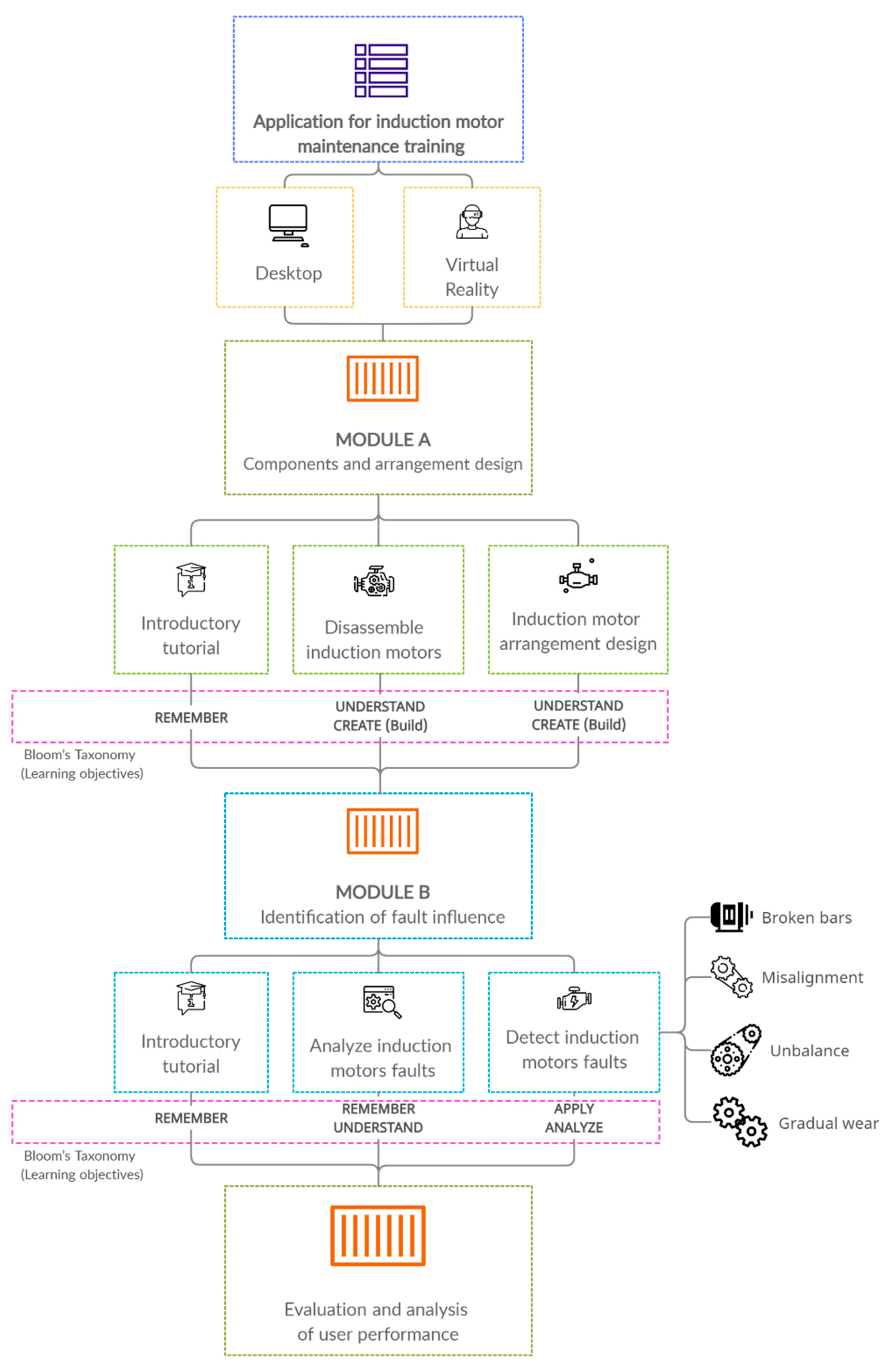
4. Materials and Methods

This section covers the design and development of the induction motor maintenance training application. In virtual reality, users learn through autonomous interaction, hands-on learning, and problem solving. For this purpose, an application was developed to take full advantage of the benefits that VR provides for training. The design of this learning experience aimed to provide (1) a realistic VR experience in which to learn and to practice the principles of induction motors and to identify some of its faults; (2) a safe environment where mistakes can be corrected; and (3) immediate feedback provided on operational learning. This design follows the idea that, rather than learning theory in a formal manner, the potential of VR lies in “learning by doing”, which is often very difficult to apply in conventional classrooms. The application is conceived as a hands-on learning environment, which helps to increase interest in the material based on the students’ preference for practice-oriented learning content rather than memorization. This application is structured into two modules: a first module, the emphasis of which is to learn about the components of an induction motor and arrangement design; and a second module, which emphasizes practicing the identification of induction motor failures (broken bars, misalignments, unbalances and gradual wear on gear teeth) and their influence on operability. Each phase of these modules uses different learning objectives as proposed in Bloom’s taxonomy [41]. The operational learning model used in this research is summarized in Figure 1, and its components are analyzed in detail in the following sections.
Module A covers the identification of the fundamental components of induction motors and basic arrangements.
In this module, the content was designed in a structured format to help users learn the components of an induction motor and integration in a kinematic chain comprised of different components besides the motor, such as gearboxes, generators, etc. These are concepts for which a higher degree of visualization and experiential awareness is required. Module A was designed so that users could progress through different levels and advance towards the following goals:
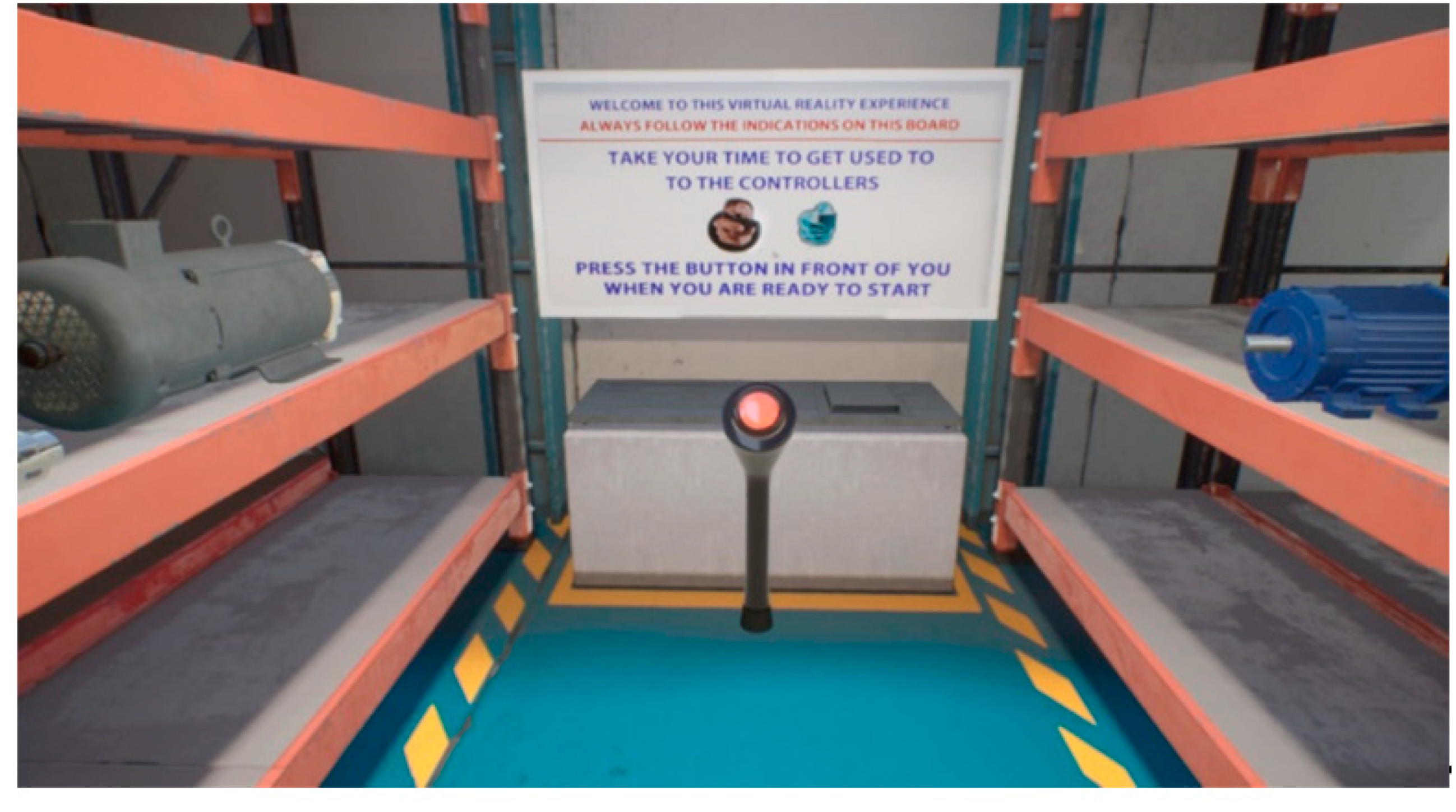
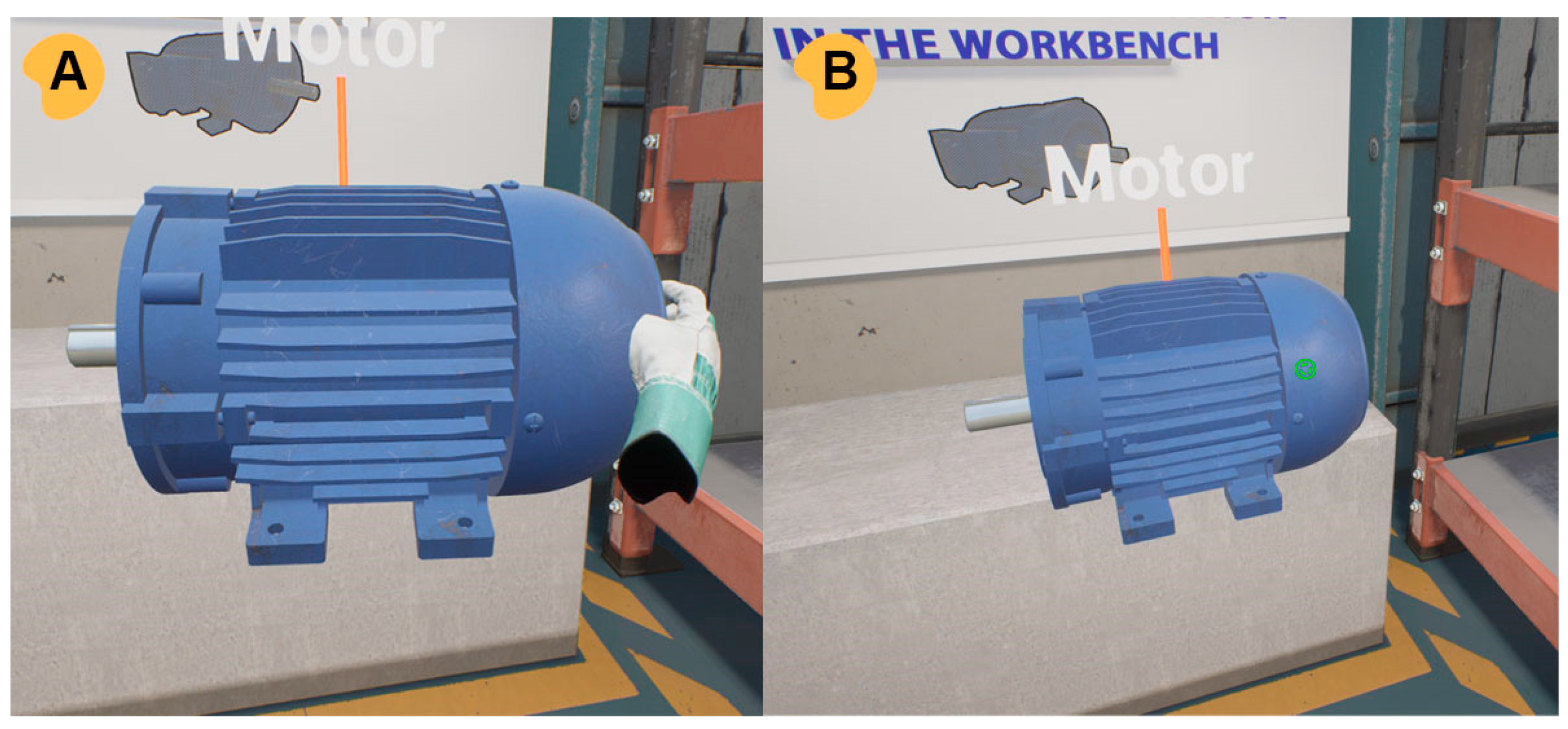
  • Introductory tutorial: In any immersive virtual reality training application, it is important for the user to have sufficient time to become familiar with the virtual reality devices. This familiarization period is important because the novelty of VR environments and interfaces can limit the user’s learning experience, especially if such devices are new to the user. Therefore, these applications must include an extensive pre-training phase, in which students acquire sufficient knowledge through their interaction with the VR environment. This level is also used to train users in how the VR interface can be used, such as by grabbing and placing objects, and through a tutorial, in which the user, guided by the instructions that appear on the board, has to assemble a motor arrangement on the workbench, as can be seen in Figure 2. The procedure is simple: first, place the induction motor, then the DC generator and finally a coupling so that the system will function. In this way, this first level serves as an introduction to the devices, and some practical and operational knowledge is shared with the student. It also serves as a learning experience of the mechanics that will be used throughout the activity and familiarizes the user with the way the information is presented. Finally, it helps mitigate any initial reaction towards the VR environment, which can reduce user attention, if presented with relevant information early on;
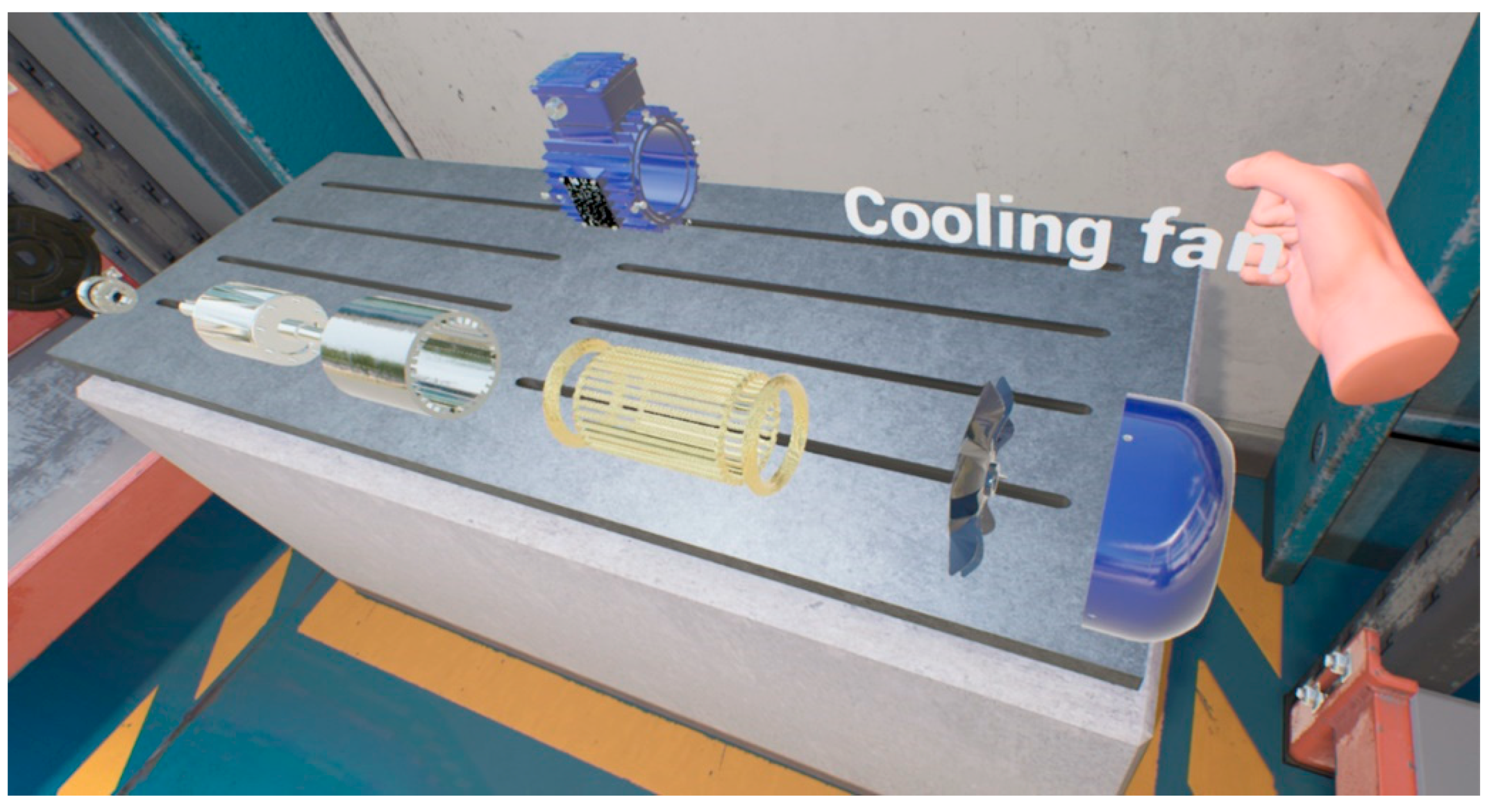
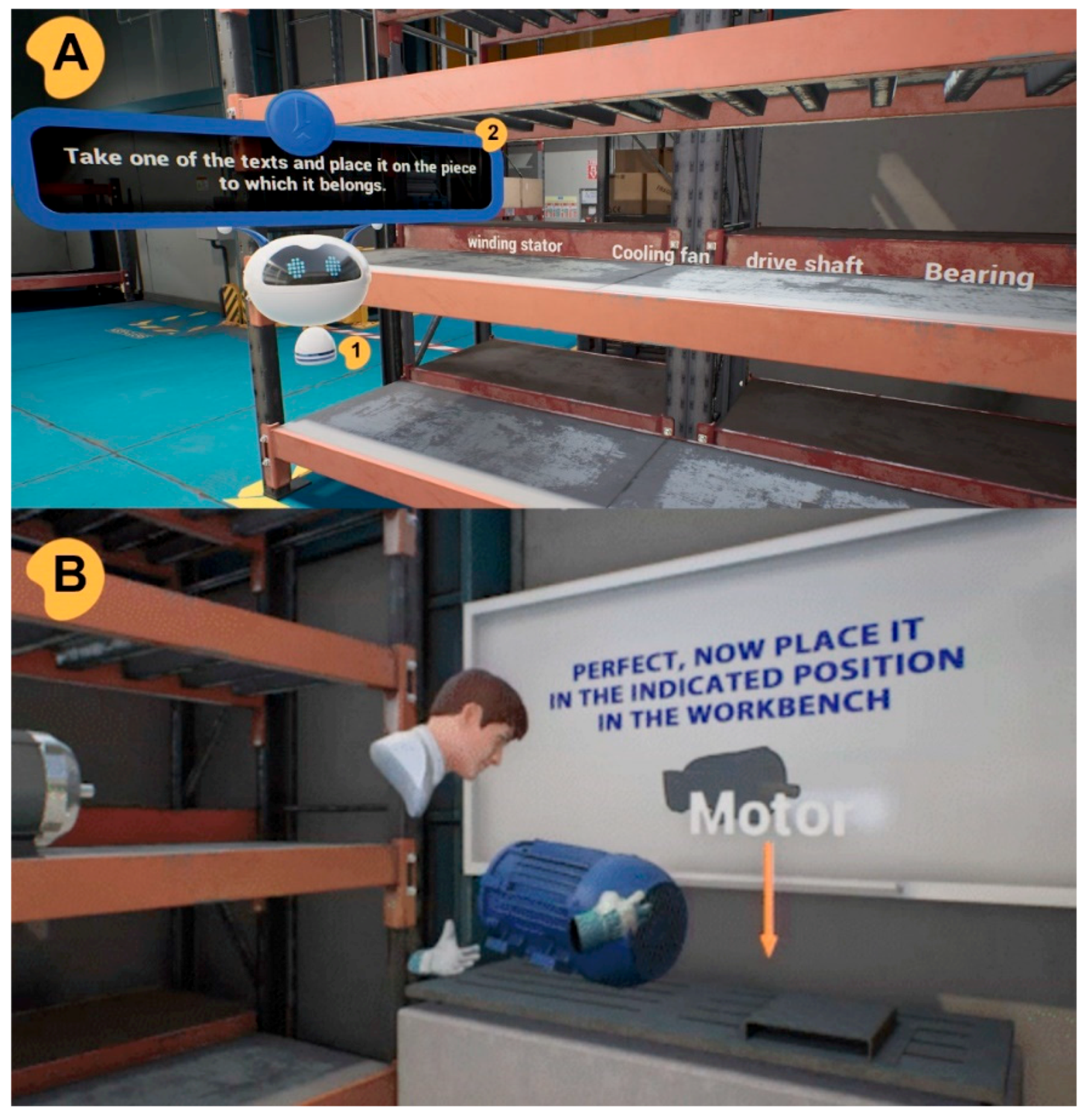
  • Disassembly of induction motors: Accurate knowledge of the components of an induction motor is essential for an understanding of its operating principles. VR provides a space with a higher degree of visualization than other less immersive environments, in which machines may be assembled and disassembled, and every part inspected in the context of the whole machine. At this level, the user interacts with a disassembled induction motor. The induction motors are composed of several parts, with the most important being the stator, rotor, shaft, bearings and frame. Individual parts can be examined closely. The objective is to identify each one of them, and to do so, the user must label them with a name, as shown in Figure 3;
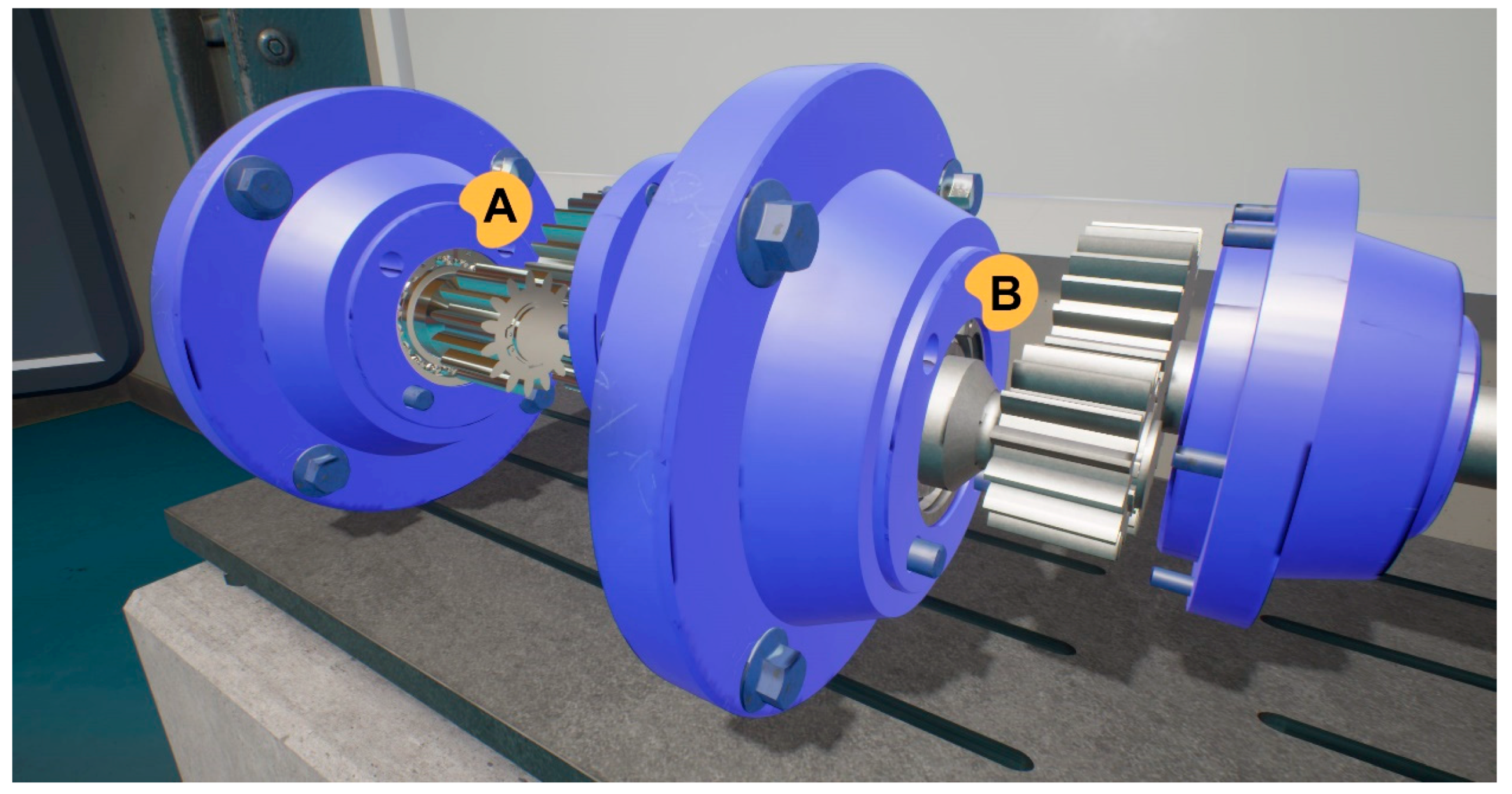
  • Induction motors arrangement design: This level has a twofold objective. On the one hand, the objective is to understand the connections between the motor and the integration of the gearboxes in the formation of a kinematic chain, which is also comprised of components such as generators and couplings. Secondly, the objective is to understand and to apply the synchronous speed equation, Equation (3). The user must, through self-instruction, select the motor and gear case arrangement that achieves the motor speed, f r , at 900 revolutions per minute (r.p.m.). For this purpose, the user has access to a large number of different motors and gear cases, as shown in Figure 4. The user has to make use of the theoretical formula, Equation (3), overprinted on the workbench, with which the problem may be solved. The arrangement is fully modifiable, so that the user can wind back the process in case of error.
Training Application module B approaches the simulation and identification of the operating state under the influence of induction motor faults.
This module aims to represent an environment where the trainee can simulate the operating state of induction motors under the influence of different faults, so that the user can learn to identify them using MCSA current analysis. Thus, the simulation of these complicated processes can be accomplished with VR tools in an efficient and cost-effective manner. Module B was designed so that users could progress through different levels and advance towards the following goals:
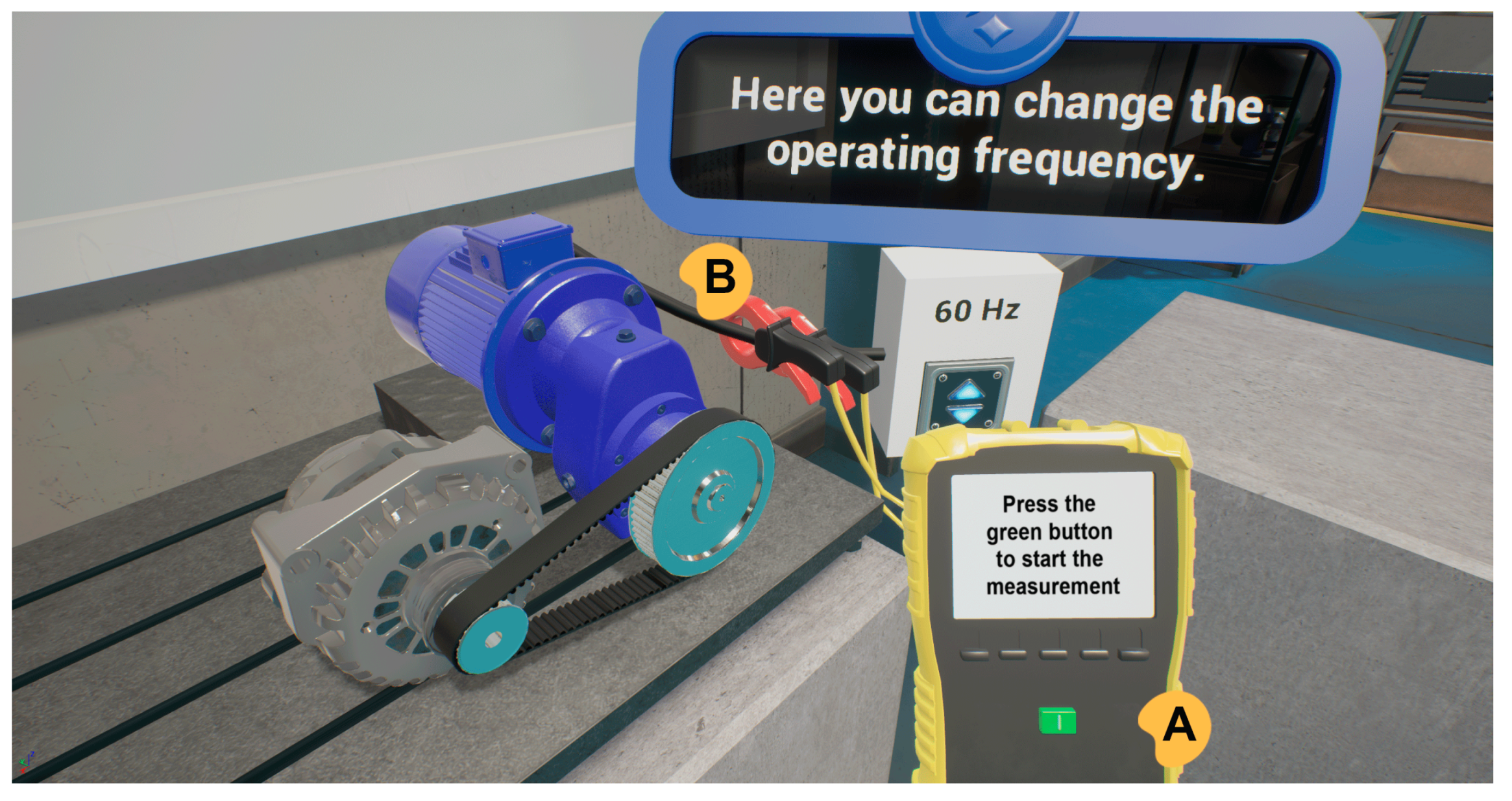
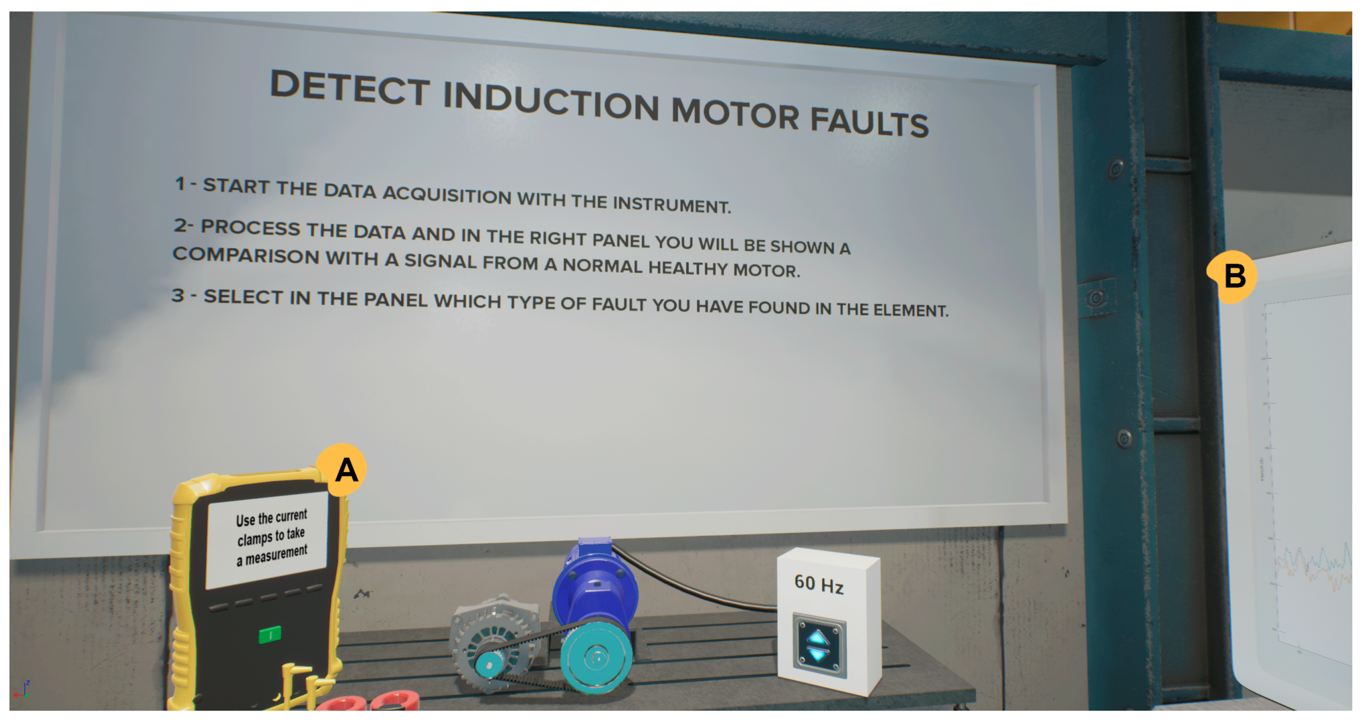
  • Introductory tutorial: This module incorporates new elements for interaction as the tasks that the user is expected to perform become more complex. At the following levels, the user will have to interact with user interfaces (UI) in order to select different faults to be simulated. Likewise, the user learns to use a device for the measurement of electrical signals (mainly current) as seen in Figure 5A, together with the clamp accessory that can quickly measure the current, as shown in Figure 5B;
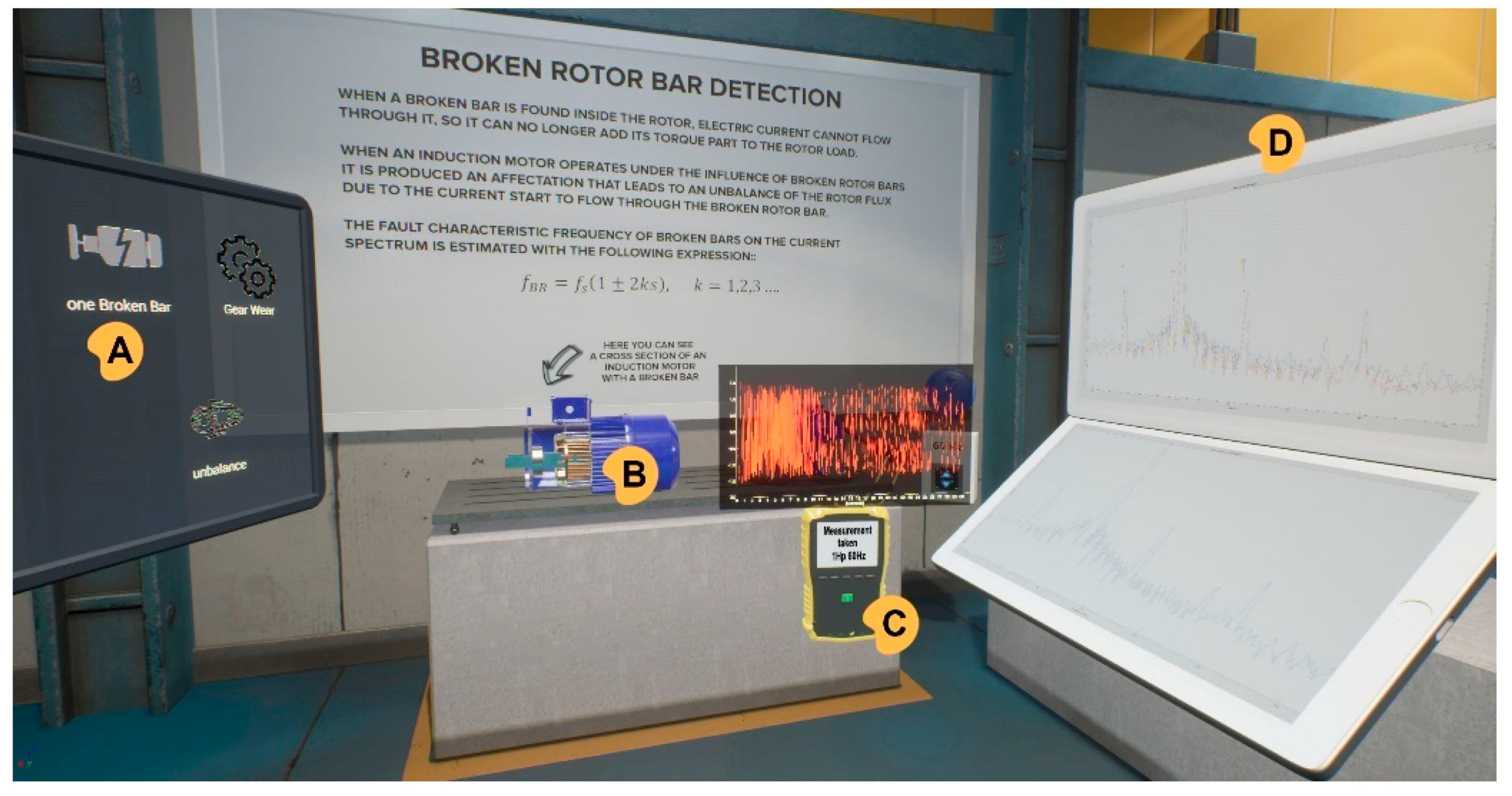
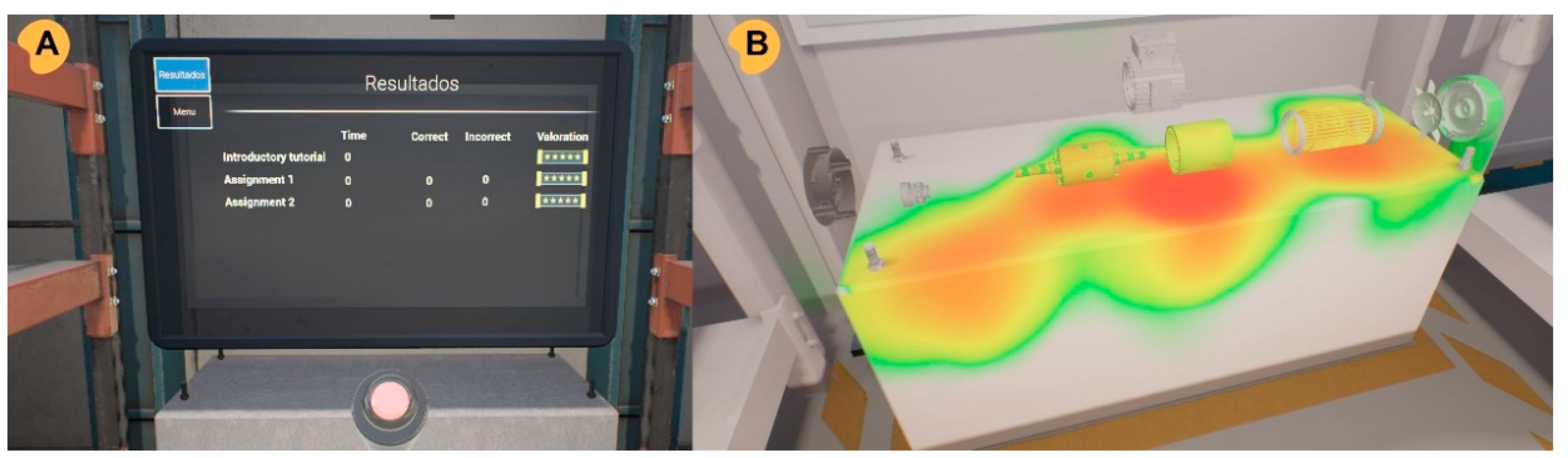
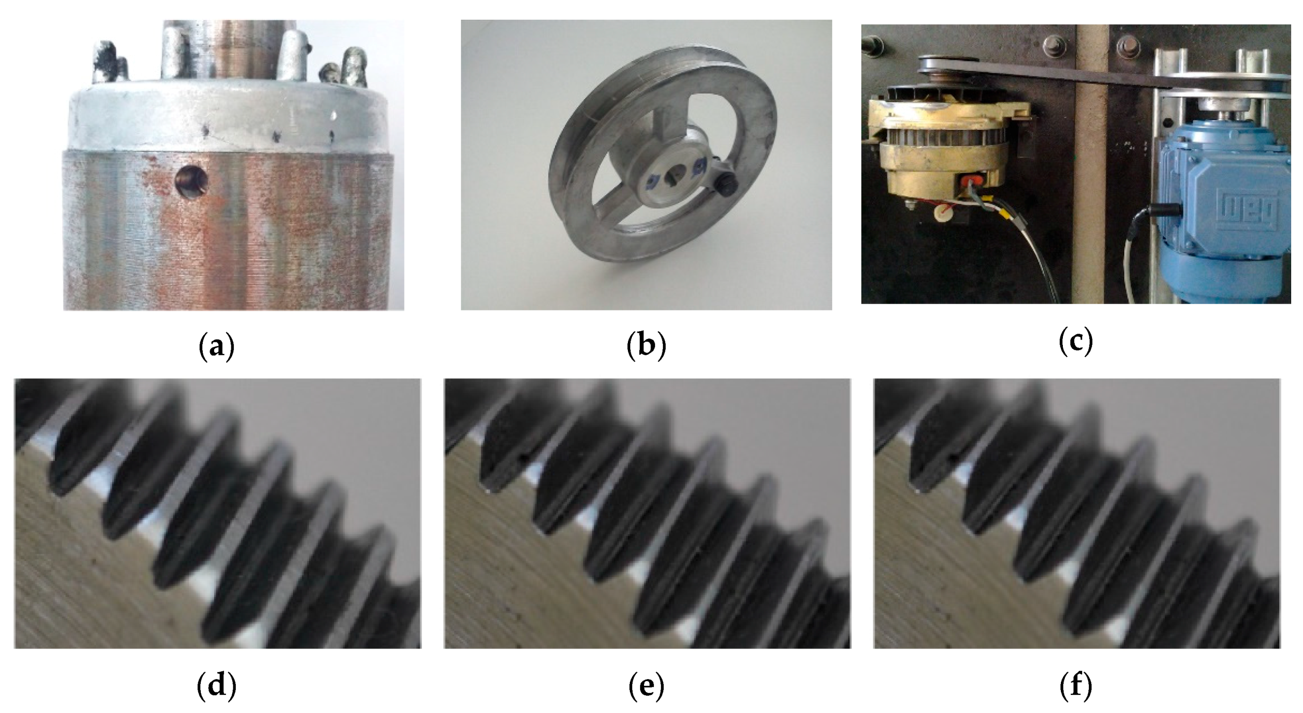
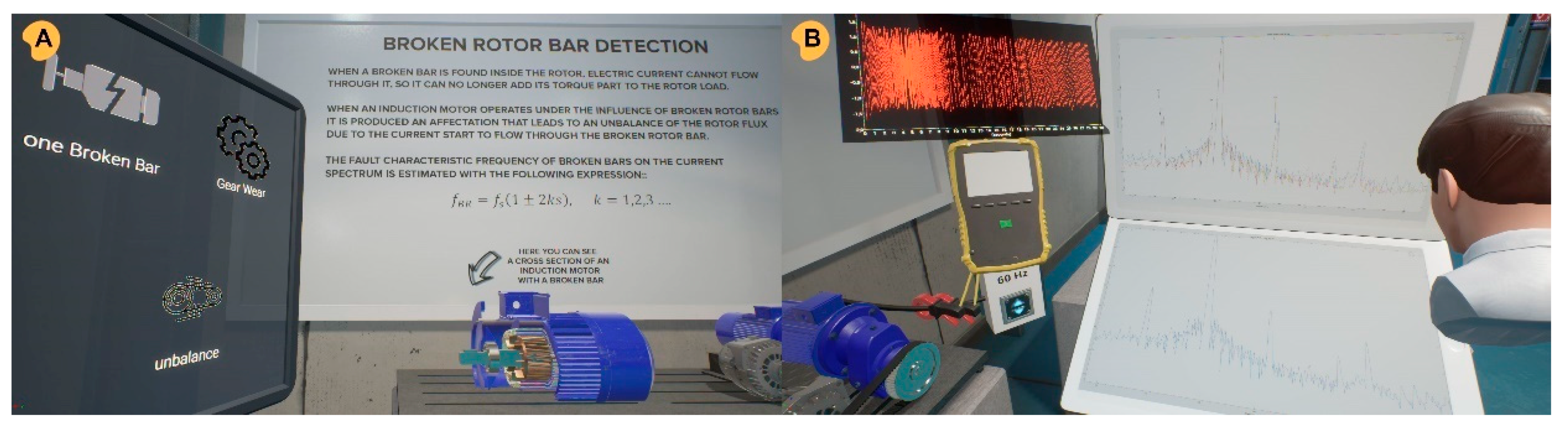
  • Analyze induction motor faults: In this phase, the user can be trained in the detection of different types of faults. In front of the user on the workbench is a system composed of an induction motor and an alternator coupled to a pulley and belt system. Using the left panel, users can select the type of fault they want to learn and how to detect it. The user can choose to simulate failures of broken bars in the induction motor, misalignments and unbalances between the induction motor and the alternator, and gearing wear (uniform gradual wear on gear teeth 25%, 50% and 75%). Once the user selects a fault in the left panel, illustrated in Figure 6A, an exploded view of the object is displayed for detailed observation of the fault, as can be seen in Figure 6B. This view is immensely useful in these contexts, as these faults are normally inside a part or in an inaccessible area and are therefore not immediately visible. The whiteboard shows relevant information on the type of fault and how to detect it. By using the measurement device, the power quality of the induction motor can be analyzed, as can be seen in Figure 6C. If the user has correctly configured the measuring device, it receives the raw signal and can display it in real time. Then, the user can examine the signal and process it by applying the fast Fourier transform to the induction motor current signature to obtain the frequency spectrum and to locate the fault-related frequency components. Additionally, the users can export the raw data at any time after capture to apply further processing to the data provided in this virtual tool. With the processed signal, the user can learn in the left side panel to detect indications in the signal that reveal the presence of the fault, as can be seen in Figure 6D. Raw data were taken from real benches and experimental data [42,43] from a real experimental bench, used to evaluate different failure conditions in the induction motor and gearing. Each fault condition was individually evaluated under different frequency values that are programmed in the frequency inverter (12 Hz, 30 Hz, 60 Hz). The user has a frequency inverter available to adjust the frequency, where the frequency to be simulated can be selected at any time. The duration of the data is 30 s, where the first 10 s correspond to the start-up transient (acceleration ramp from 0 to 10 s), and the remaining 20 s belong to the steady state of the motor. The users can remain at this level as long as desired and perform the necessary tests and comparisons between different types of failure to consolidate their knowledge.
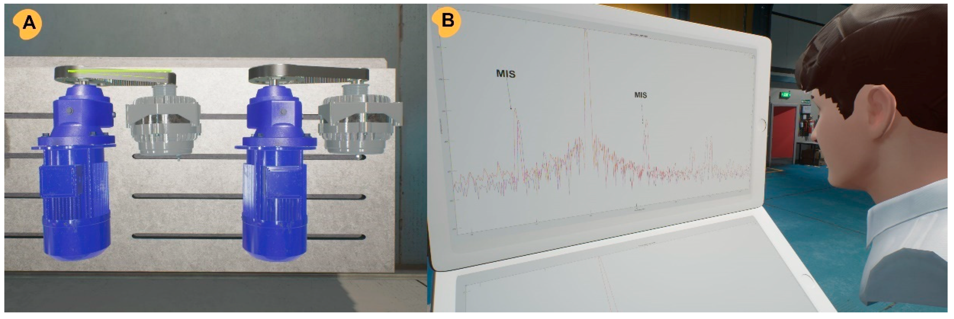
  • Detect induction motor faults: At this level, the user will have to apply the knowledge acquired and should be able to detect which of the possible failures (broken bars, gradual wear, misalignments and unbalances) are randomly generated in the motor arrangement. The process is the same as the one used in practice, but this time without the detailed help panels. The process starts with data acquisition (Figure 7A)and its processing, and according to this data, the user will have to decide what type of failure the system is simulating by comparing it to a signal from a normal component (Figure 7B).

Evaluation and Analysis of User Performance Module

This module collects the user’s information during the different levels. It does not store only the evaluation criteria, as can be seen in Table 1, but also collects data on the whole performance of the user (eye tracking, 3D positions, interactions...). At the end of the experience, the performance of the trained personnel is briefly reviewed, as shown in Figure 8A. However, having collected such a large amount of data, it is possible to analyze the user’s performance in greater depth. For this purpose, a specific tool was developed to observe and to analyze human performance. From the data collected by the HMD eye-tracking module, the recorded gaze data can be visualized and processed. The tool can superimpose the fixations on the scene and use them to create heat maps and areas of interest. Thus, an analysis of user observations of the scene is shown in image 8B. It can identify bottlenecks in the process by seeing where users had difficulties. It provides trainers with a quantitative way of measuring user compliance.
The application was developed with the support of a previously created framework [44] that simplified the application development process with pre-programmed functions and services for their effective reuse, such as player utilities, an evaluation manager and tools for metrics. This framework also makes a single project possible that can be used on a 2D screen or on VR devices, merely by changing the pawn that automatically detects whether or not the user has connected a compatible VR device. On the one hand, if the user plays on a 2D screen, the interface will be the mouse and the keyboard; on the other hand, if a VR device is used, the interaction will be through hand controllers. The application is designed for HTC Vive, but also works with Oculus headsets and controllers and Windows Mixed Reality headsets and controllers.
If used on 2D screens, the interaction in the application is controlled with a keyboard and a mouse by using the left click to pick up, to drop, and to place objects. The movements use the arrows or AWSD of the keyboard. Figure 9A shows a user interacting with the application with an HMD and Figure 9B shows the same action in a desktop version.
Application design decisions were taken to achieve natural interactions and to mitigate any usability constraints of the controllers. The application design was focused on usability with a limited interaction technique in VR to accelerate the learning curve of the user: among the 3 basic forms of interaction techniques in VR (selection, manipulation and locomotion), the user only had to focus on the manipulation of objects. A single mechanism was used to pick up, to drop and to place objects in position. The user had to press and to hold the controller trigger to pick up objects and the hand dropped the objects when the button was released. An attachment system was programmed to help the user to place the object in the desired position when it was sufficiently close to the attachment point to facilitate the assembly tasks. The outline of the hand was also highlighted in a light green color whenever within range of an object to facilitate grabbing. The objects floated back to their original locations a few seconds after being released to prevent users from accidentally dropping or throwing parts away. This design solution avoided the use of a specific button-based mechanism, which could be difficult for a novice user. Additionally, a virtual assistant, as can be seen in Figure 10A1, was programmed to guide and to assist the user through the different steps. This intelligent instructor gives clues on the tasks to be performed at each stage, as can be seen in Figure 10A2. The user can also choose the level of help it provides. It is programmed in such a way that if it detects that the user may be stuck in some part of the training, it can flash up tips on the screen to solve the situation correctly. Finally, one of the problems with virtual reality is that the trainer can usually only see what the user is seeing. This greatly limits the evaluation of the trainee’s performance. For this reason, a spectator view has been created, whereby the trainer can be integrated as a user into the virtual environment. This means that the trainer can see the user performing the tasks from any point of view for a better analysis of user behavior in the virtual environment, as can be seen in Figure 10B.
A summary of the design guidelines of the application and the learning objectives and evaluation criteria developed for these condition-based maintenance training modules on induction motors can be found in Table 1.

5. Application Validation and User Testing of the VR-Tool Application

Special emphasis was placed on failure case studies to evaluate the accessibility, efficiency and commitment of the system as a whole (both modules) due to the novelty of integrating and processing raw data in the application. In the application, the user can train with the mentioned faults that can be found in induction motors and that can be appreciated in Figure 11; each one of the faults was artificially generated, e.g., the broken rotor bar was generated by drilling a hole that damaged one of the bars, the unbalance was induced by attaching a bolt simulating an eccentricity mass, and the misalignment was produced by a parallel bar misaligning the pulleys. On the other hand, regarding the fault of uniform wear that was analyzed in a gearbox, each one of the three levels, 25%, 50% and 75%, were artificially induced by a gear factory and all the teeth of the gearing were uniformly worn.
Broken rotor bar: The application can be used to monitor the stator current signal for detecting rotor faults in induction motors. Motor current signature analysis (MCSA) is an effective technique that can detect fault occurrence in induction motors. It basically relies on the analysis of current signatures by means of different techniques such as the fast Fourier transform (FFT). As mentioned above, when an induction motor operates under the influence of broken rotor bars, an affectation is produced that leads to a distortion of the airgap magnetic field that will induce some components in the stator current signal. In an estimated current spectrum, these components appear as sideband harmonics around the supply frequency, f s ; according to Equation (2), first-order side-bands components may appear at (1) when k = 1, and these first-order components are the most significant for detecting the occurrence of faults associated with broken rotor bars. The user must first learn how to identify this failure in virtual reality, as shown in Figure 12A, through an inspection of the cross-section of a motor. The user can visualize this failure of internal parts thanks to that arrangement in order to better understand the inspected elements. Second, as shown in Figure 12B, the user proceeds to the measurement phase; the raw data are automatically processed (although it should be noted that the data were available for export from the application if the user wished to apply other processes) and the result is displayed in the lower panel. In the upper panel, the user can see this processed sample compared with a sample from a normal motor. In addition, it shows where to look for the evidence of a broken bar failure in an induction motor;
Unbalance and misalignment: Eccentricity problems occur due to uneven airgaps between the stator and rotor. In the presence of eccentricities, low-frequency sidebands appear in the stator current spectrum given in Equation (3). The existence of these harmonics is due to the interaction between the two most common types of eccentricities, static and dynamic. Misalignment problems can be detected in induction motors through the following current spectral analysis in Equation (4). To learn how to identify this failure in virtual reality, the user can first inspect the different parts involved in unbalance and misalignment problems. Figure 13A shows an example of misalignment problems that the user can explore and perceive better in virtual reality through stereoscopic visualization and observation of the elements from any angle. Second, as in previous levels, the user proceeds to measurement. Processed data is displayed in the lower panel. In the upper panel, the user can see the processed sample compared with a sample from a normal motor. In addition, it shows where to look for the evidence of unbalance or misalignment failures in an induction motor, as shown in Figure 13B;
Gear wear: MCSA has also been applied as a part of the condition assessment approaches to identify faulty rotating mechanical elements such as gearboxes. Gradual wear on gear teeth was simulated with a 0% wear condition and 3 conditions of uniform wear on gear teeth of 25%, 50% and 75%. Variations of simulated wear under different wear conditions can be seen in detail in Figure 14. The identification of gearbox faults can be carried out by analyzing specific fault-related frequency components using Equation (7).

6. Discussion

Before the widespread use of the application, its usability must be validated. Module A validation was carried out with 18 bachelor’s degree students studying mechanical manufacturing. This test had two objectives. Firstly, as a stress test of the virtual reality headset, this test aimed to check its performance, data acquisition and how it adapts to different environments; secondly, as a mSUPPethod, this test aimed to detect errors in the different levels and the possible need for refinement of the mechanics (grab, attach, interaction with UI, etc.). One of the minor problems detected was that the user position was reset to where the previous level had ended when passing from one level to another, which caused a mismatch with respect to the initial calibration. This mismatch could mean that two trainees would collide. To solve this problem, the initial calibration was forced at the start of each level. Regarding the training objectives of this module, the teachers highlighted the importance of applications that facilitate a basic understanding of the operating condition of induction motors. They also remarked on the possibilities of training with a wide variety of different elements without having to make a large investment in the facility. They also highlighted the importance of virtual reality as a more immersive medium where students will better understand spatial concepts and increase their motivation. However, the logistics of getting all the students into the application can be challenging due to the difficulty of having many HMDs in a classroom. On the other hand, this same application, in its flat-screen version, although less immersive, was considered usable for any of these courses and might also provide extra motivation to the students.
Thus, understanding the basis of the operational condition of an induction motor is an essential aspect of the training program, as is the effective detection of fault occurrence in induction motors. Condition monitoring approaches are important to detect unexpected faults that may compromise the efficiency of industrial processes and cause inevitable and excessive energy consumption. The occurrence of faults in induction motors can be effectively detected with MCSA. The practical implementation of MCSA may represent a complicated task and is very critical when trying to train new maintenance technicians. Therefore, having data from real experimental test benches and virtual reality tools is a solution for training. In the second module, MCSA is used to detect induction motor failures such as broken rotor bars, misalignments, unbalances, and gradual wear on gearing teeth.
A validation was performed with 16 students from the master’s degree program in multimedia development to evaluate the accessibility and the efficiency of the VR application (Supplementary Materials). This validation is the first step in the final validation of the VR application, while a second step requires the validation of the learning outcomes. This second step is traditionally [1] the subject of later research, due to its complexity, and it is not included in this research due to length limitations. Besides, as this VR educational experience approach concerns learning by doing in relation to a real industrial task, its objectives are reached once the student has spent time enjoying solving design problems in an autonomous way, because demotivation and monotony play a major role in poor learning performance among students. The students were asked about the potential of the VR application as a training tool and the modifications needed to improve it. The design of the survey was adapted from a questionnaire to measure the user experience in immersive virtual environments [45]. From the survey results (Figure 15), the users reported very high satisfaction with the experience (75% highest rating) and believed that this simulator can help them in the teaching of and training in induction motors (73% strongly agree). As highlighted, opinions were positive towards the interaction design. This is a complex and challenging process, but a special effort was made to achieve natural interactions as well as to mitigate any usability constraints of the controllers. The user only had to focus on the manipulation of objects to accelerate the learning curve. A single mechanism was used to pick up and to drop objects as well as to place them in position. Additionally, an attachment system was programmed to help the user to place the object in the desired position. Results that invite reflection are, for example, those related to the following questions: at each step did you know what to do, as a large group can be lost at certain times. Gaze and eye-position data were studied from the data that had been collected in order to reduce this problem. These data showed that some users have problems understanding what to do in some exercises until they seek help from the virtual assistant. Therefore, this virtual assistant was programmed to take the initiative much earlier. Small fonts used in some information panels were also corrected to improve comprehension. However, the information provided in the application was considered sufficiently clear and explanatory by these users. Results from users reported a high level of immersion in the experience, which can still be improved, as some users commented that they lost the sense of immersion when hearing the outside world due to the lack of ambient sound in the application. For these reasons, a sufficiently audible industrial ambient sound was programmed to help with user immersion. Finally, more than half of the users reported finding the visual aspects realistic. This aspect is important because the application achieves the four key objectives of a VR-tool: interaction, immersion, user involvement and photorealism [46].

7. Conclusions

In this work, the development of a VR-based application for teaching and training for condition-based maintenance in induction motors is presented. The widespread use of induction motors makes it necessary to understand the basis of their operation condition as an essential aspect of any maintenance program. Additionally, the implementation of condition-based maintenance programs aims to safeguard their operating condition and its availability. The application has two training modules. The first was focused on the main components of induction motors, the assembly of workbenches and familiarization with the elements of induction motors. The second module employs motor current signature analysis to detect induction motor failures, such as broken rotor bars, misalignments, unbalances, and gradual wear on gear teeth. The practical implementation of MCSA represents a difficult task and is crucial in the training of new maintenance technicians. Therefore, this application, with embedded data from real experimental test benches and the correct use of virtual reality tools, is a solution for training these aspects.
The tool has been designed considering that, in VR educational applications, the “novelty effect” and the user’s amazement for the innovative technology of using HMDs must be minimized. Moreover, the design of this tool aims to avoid reductions in learning efficiency due to a lack of control of the VR interface. For this purpose, different introductory levels have been designed in the form of interactive tutorials, placing special emphasis on creating natural user interfaces. This application follows the idea that, rather than learning theory in a formal manner, the real potential of VR lies in “learning by doing”. There are many factors why this cannot be done in traditional trainings, such as access to the material or its high cost. This virtual reality application helps to increase interest in the material based on the students’ preference for practice-oriented learning content. Thus, through VR tools, the simulation of these complicated processes can be accomplished in an efficient and cost-effective manner. During the validation, an analysis of a satisfaction/usability test was performed, and the satisfaction and belief of its usability with students was found to be very high. This result is particularly interesting in the context of the SARS-CoV-2 (COVID-19) crisis, which highlights the growing demand for distance learning content.
Future studies will look at the massive assessment of the training capacity of the application to determine its suitability for its possible inclusion in regular educational programs, where learning outcomes should also be evaluated and compared with other learning methodologies. Moreover, an additional prospective avenue for this research to follow is that the improvement of this VR-based application will facilitate any demonstration of the importance of induction motor efficiency for energy efficiency, operational expenses and how the system losses will build up in the different applications. Finally, the application makes use of motor current signature analysis (MCSA) to detect induction motor failures such as broken rotor bars, misalignments, unbalances, and gradual wear on gearing teeth. It is expected to address the incorporation of other methods as well as the simulation of its operating working condition under the influence of additional faults of induction motors, focusing on the detection of multiple and/or combined faults.

Supplementary Materials

The VR application is available for download at the following URL: https://3dubu.es/en/electricmotors.

Author Contributions

Conceptualization, D.C. and R.A.O.-R.; methodology, D.C., J.J.S.-D., and A.B.; validation, J.J.S.-D. and D.C.; formal analysis, D.C. and R.A.O.-R.; investigation, J.A.A.-D. and J.J.S.-D.; resources, J.A.A.-D.; data curation, A.B. and J.J.S.-D.; writing—original draft preparation, D.C.; writing—review and editing, D.C., R.A.O.-R., and J.A.A.-D.; visualization, D.C. and J.J.S.-D.; supervision, A.B., R.A.O.-R., and J.A.A.-D.; project administration, R.A.O.-R. and J.A.A.-D.; funding acquisition, J.A.A.-D. All authors have read and agreed to the published version of the manuscript.

Funding

This research has been partially supported by Banco Santander under the scholarship program Santander Iberoamérica Research 2019/20. This investigation was partially supported by the ACIS project (Reference Number INVESTUN/21/BU/0002) of the Consejeria de Empleo of the Junta de Castilla y León (Spain).

Institutional Review Board Statement

Not applicable.

Informed Consent Statement

Not applicable.

Data Availability Statement

The data that support the findings of this study (VR tool’s usability validation with different students) are available on request from the corresponding author.

Conflicts of Interest

The authors declare no conflict of interest.

References

  1. Checa, D.; Bustillo, A. A review of immersive virtual reality serious games to enhance learning and training. Multimed. Tools Appl. 2020, 79, 5501–5527. [Google Scholar] [CrossRef] [Green Version]
  2. Lele, A. Virtual reality and its military utility. J. Ambient Intell. Humaniz. Comput. 2013, 4, 17–26. [Google Scholar] [CrossRef]
  3. Pallavicini, F.; Argenton, L.; Toniazzi, N.; Aceti, L.; Mantovani, F. Virtual Reality Applications for Stress Management Training in the Military. Aerosp. Med. Hum. Perform. 2016, 87, 1021–1030. [Google Scholar] [CrossRef] [PubMed]
  4. Checa, D.; Martínez, K.; Osornio-Ríos, R.; Bustillo, A. Virtual Reality opportunities in the reduction of occupational hazards in industry 4.0. DYNA 2021, 96, 620–626. [Google Scholar] [CrossRef]
  5. Gawlik-Kobylińska, M.; MacIejewski, P.; Lebiedź, J.; Wysokińska-Senkus, A. Factors Affecting the Effectiveness of Military Training in Virtual Reality Environment. In Proceedings of the PervasiveHealth: Pervasive Computing Technologies for Healthcare, Oxford, UK, 11–13 February 2020. [Google Scholar]
  6. Choni, Y.; Dardymov, A. Advantages and “pitfalls” of applying virtual laboratory works in technology education. In Proceedings of the AIP Conference Proceedings, Erode, India, 21–22 November2019; Volume 2195. [Google Scholar]
  7. Valdez, M.T.; Ferreira, C.M.; Martins, M.J.M.; Barbosa, F.P.M. 3D virtual reality experiments to promote electrical engineering education. In Proceedings of the 2015 International Conference on Information Technology Based Higher Education and Training (ITHET), Lisbon, Portugal, 11–13 June 2015; pp. 1–4. [Google Scholar]
  8. Singh, G.; Mantri, A.; Sharma, O.; Kaur, R. Virtual reality learning environment for enhancing electronics engineering laboratory experience. Comput. Appl. Eng. Educ. 2021, 29, 229–243. [Google Scholar] [CrossRef]
  9. Mikropoulos, T.A.; Natsis, A. Educational virtual environments: A ten-year review of empirical research (1999–2009). Comput. Educ. 2011, 56, 769–780. [Google Scholar] [CrossRef]
  10. Stapleton, A.J. Serious Games: Serious Opportunities. In Proceedings of the Australian Game Developers’ Conference, Melbourne, Australia, 2–4 December 2004. [Google Scholar]
  11. González Campos, J.S.; Sánchez-Navarro, J.; Arnedo-Moreno, J. An empirical study of the effect that a computer graphics course has on visual-spatial abilities. Int. J. Educ. Technol. High. Educ. 2019, 16, 41. [Google Scholar] [CrossRef] [Green Version]
  12. Arabul, F.K.; Senol, I.; Oner, Y. Performance analysis of axial-flux induction motor with skewed rotor. Energies 2020, 13, 4991. [Google Scholar] [CrossRef]
  13. Choudhary, A.; Goyal, D.; Shimi, S.L.; Akula, A. Condition Monitoring and Fault Diagnosis of Induction Motors: A Review. Arch. Comput. Methods Eng. 2019, 26, 1221–1238. [Google Scholar] [CrossRef]
  14. Bonet-Jara, J.; Quijano-Lopez, A.; Morinigo-Sotelo, D.; Pons-Llinares, J. Sensorless speed estimation for the diagnosis of induction motors via mcsa. Review and commercial devices analysis†. Sensors 2021, 21, 5037. [Google Scholar] [CrossRef]
  15. Liu, Y.; Bazzi, A.M. A review and comparison of fault detection and diagnosis methods for squirrel-cage induction motors: State of the art. ISA Trans. 2017, 70, 400–409. [Google Scholar] [CrossRef]
  16. Karami, M.; Mariun, N.B.; Ab-Kadir, M.Z.A.; Misron, N.; Mohd Radzi, M.A. Motor Current Signature Analysis-based Non-invasive Recognition of Mixed Eccentricity Fault in Line Start Permanent Magnet Synchronous Motor. Electr. Power Compon. Syst. 2021, 49, 133–145. [Google Scholar] [CrossRef]
  17. Naranjo, J.E.; Sanchez, D.G.; Robalino-Lopez, A.; Robalino-Lopez, P.; Alarcon-Ortiz, A.; Garcia, M.V. A scoping review on virtual reality-based industrial training. Appl. Sci. 2020, 10, 8224. [Google Scholar] [CrossRef]
  18. Ayala García, A.; Galván Bobadilla, I.; Arroyo Figueroa, G.; Pérez Ramírez, M.; Muñoz Román, J. Virtual reality training system for maintenance and operation of high-voltage overhead power lines. Virtual Real. 2016, 20, 27–40. [Google Scholar] [CrossRef]
  19. Roldán, J.J.; Crespo, E.; Martín-Barrio, A.; Peña-Tapia, E.; Barrientos, A. A training system for Industry 4.0 operators in complex assemblies based on virtual reality and process mining. Robot. Comput. Integr. Manuf. 2019, 59, 305–316. [Google Scholar] [CrossRef]
  20. Müller, D.; Ferreira, J.M.M. MARVEL: A mixed reality learning environment for vocational training in mechatronics. In Proceedings of the T.E.L. ’03 Proceedings: International Conference on Technology-Enhanced Learning, Milan, Italy, November 2004. [Google Scholar]
  21. Travassos Valdez, M.; Machado Ferreira, C.; Martins, M.J.M.; Maciel Barbosa, F.P. Virtual labs in electrical engineering education-The VEMA environment. In Proceedings of the ITHET 2014—13th International Conference on Information Technology Based Higher Education and Training, York, UK, 11–13 September 2014. [Google Scholar]
  22. Perez-Ramirez, M.; Arroyo-Figueroa, G.; Ayala, A. The use of a virtual reality training system to improve technical skill in the maintenance of live-line power distribution networks. Interact. Learn. Environ. 2021, 29, 527–544. [Google Scholar] [CrossRef]
  23. Kamińska, D.; Zwoliński, G.; Wiak, S.; Petkovska, L.; Cvetkovski, G.; Barba, P.D.; Mognaschi, M.E.; Haamer, R.E.; Anbarjafari, G. Virtual Reality-Based Training: Case Study in Mechatronics. Technol. Knowl. Learn. 2021, 26, 1043–1059. [Google Scholar] [CrossRef]
  24. Ibrahim, N.S.I.; Akin, E. Virtual Reality For Electrical Machine. Int. J. Sci. Res. Manag. 2021, 9, 586–596. [Google Scholar] [CrossRef]
  25. Cvetkovski, G.; Petkovska, L.; Digalovski, M.; Celeska, M.; Kamińska, D.; Firych-Nowacka, A.; Wiak, S.; Sapiński, T.; Lefik, M.; Zwoliński, G.; et al. Virtual Reality as a Tool for Electrical Machines Assembling and Testing. In Proceedings of the 7th International Symposium on Applied Electromagnetics SAEM 18, Podčetrtek, Slovenia, 17–20 June 2018. [Google Scholar]
  26. Abich, J.; Parker, J.; Murphy, J.S.; Eudy, M. A review of the evidence for training effectiveness with virtual reality technology. Virtual Real. 2021, 25, 919–933. [Google Scholar] [CrossRef]
  27. Checa, D.; Miguel-Alonso, I.; Bustillo, A. Immersive virtual-reality computer-assembly serious game to enhance autonomous learning. Virtual Real. 2021. [Google Scholar] [CrossRef]
  28. Hassan, O.E.; Amer, M.; Abdelsalam, A.K.; Williams, B.W. Induction motor broken rotor bar fault detection techniques based on fault signature analysis—A review. IET Electr. Power Appl. 2018, 12, 895–907. [Google Scholar] [CrossRef]
  29. Asad, B.; Vaimann, T.; Belahcen, A.; Kallaste, A.; Rassõlkin, A.; Iqbal, M.N. Broken rotor bar fault detection of the grid and inverter-fed induction motor by effective attenuation of the fundamental component. IET Electr. Power Appl. 2019, 13, 2005–2014. [Google Scholar] [CrossRef]
  30. Garcia-Calva, T.A.; Morinigo-Sotelo, D.; Garcia-Perez, A.; Camarena-Martinez, D.; de Jesus Romero-Troncoso, R. Demodulation Technique for Broken Rotor Bar Detection in Inverter-Fed Induction Motor Under Non-Stationary Conditions. IEEE Trans. Energy Convers. 2019, 34, 496–1503. [Google Scholar] [CrossRef]
  31. Verma, A.K.; Sarangi, S.; Kolekar, M.H. Experimental investigation of misalignment effects on rotor shaft vibration and on stator current signature. J. Fail. Anal. Prev. 2014, 14, 125–138. [Google Scholar] [CrossRef]
  32. Ewert, P. The application of the bispectrum analysis to detect the rotor unbalance of the induction motor supplied by the mains and frequency converter. Energies 2020, 13, 3009. [Google Scholar] [CrossRef]
  33. Buttussi, F.; Chittaro, L. Effects of different types of virtual reality display on presence and learning in a safety training scenario. IEEE Trans. Vis. Comput. Graph. 2018, 24, 1063–1076. [Google Scholar] [CrossRef]
  34. Jensen, L.; Konradsen, F. A review of the use of virtual reality head-mounted displays in education and training. Educ. Inf. Technol. 2018, 23, 1515–1529. [Google Scholar] [CrossRef] [Green Version]
  35. Molina-Carmona, R.; Pertegal-Felices, M.L.; Jimeno-Morenilla, A.; Mora-Mora, H. Virtual Reality learning activities for multimedia students to enhance spatial ability. Sustainability 2018, 10, 1074. [Google Scholar] [CrossRef] [Green Version]
  36. Salah, A.A.; Dorrell, D.G.; Guo, Y. A review of the monitoring and damping unbalanced magnetic pull in induction machines due to rotor eccentricity. IEEE Trans. Ind. Appl. 2019, 55, 2569–2580. [Google Scholar] [CrossRef]
  37. Pietrzak, P.; Wolkiewicz, M. Application of Spectral and Wavelet Analysis of Stator Current to Detect Angular Misalignment in PMSM Drive Systems. Power Electron. Drives 2021, 6, 42–60. [Google Scholar] [CrossRef]
  38. Saucedo-Dorantes, J.J.; Delgado-Prieto, M.; Ortega-Redondo, J.A.; Osornio-Rios, R.A.; Romero-Troncoso, R.D.J. Multiple-Fault Detection Methodology Based on Vibration and Current Analysis Applied to Bearings in Induction Motors and Gearboxes on the Kinematic Chain. Shock Vib. 2016, 2016, 5467643. [Google Scholar] [CrossRef]
  39. Jin, X.; Cheng, F.; Peng, Y.; Qiao, W.; Qu, L. Drivetrain gearbox fault diagnosis: Vibration-and current-based approaches. IEEE Ind. Appl. Mag. 2018, 24, 56–66. [Google Scholar] [CrossRef]
  40. Kia, S.H.; Henao, H.; Capolino, G.A. Gear tooth surface damage fault detection using induction machine stator current space vector analysis. IEEE Trans. Ind. Electron. 2015, 62, 1866–1878. [Google Scholar] [CrossRef]
  41. Bloom, B.S. Taxonomy of Educational Objectives: The Classification of Educational Goals, 1st ed.; Longman Group: Harlow, UK, 1956. [Google Scholar]
  42. Juez-Gil, M.; Saucedo-Dorantes, J.J.; Arnaiz-González, Á.; López-Nozal, C.; García-Osorio, C.; Lowe, D. Early and extremely early multi-label fault diagnosis in induction motors. ISA Trans. 2020, 106, 367–381. [Google Scholar] [CrossRef]
  43. Saucedo-Dorantes, J.J.; Jaen-Cuellar, A.Y.; Delgado-Prieto, M.; Romero-Troncoso, R. de J.; Osornio-Rios, R.A. Condition monitoring strategy based on an optimized selection of high-dimensional set of hybrid features to diagnose and detect multiple and combined faults in an induction motor. Meas. J. Int. Meas. Confed. 2021, 178, 109404. [Google Scholar] [CrossRef]
  44. Checa, D.; Gatto, C.; Cisternino, D.; De Paolis, L.T.; Bustillo, A. A Framework for Educational and Training Immersive Virtual Reality Experiences. In Augmented Reality, Virtual Reality, and Computer Graphics; De Paolis, L.T., Bourdot, P., Eds.; Springer International Publishing: Cham, Switzerland, 2020; pp. 220–228. [Google Scholar]
  45. Tcha-Tokey, K.; Christmann, O.; Loup-Escande, E.; Richir, S. Proposition and Validation of a Questionnaire to Measure the User Experience in Immersive Virtual Environments. Int. J. Virtual Real. 2016, 16, 33–48. [Google Scholar] [CrossRef]
  46. Roussos, M.; Johnson, A.; Moher, T.; Leigh, J.; Vasilakis, C.; Barnes, C. Learning and Building Together in an Immersive Virtual World. Presence Teleoperators Virtual Environ. 1999, 8, 247–263. [Google Scholar] [CrossRef]
Figure 1. Operational learning model developed for induction motor maintenance training.
Applsci 12 00414 g001
Figure 2. Introductory tutorial.
Applsci 12 00414 g002
Figure 3. Disassembly of induction motors.
Applsci 12 00414 g003
Figure 4. Induction motor arrangement design level.
Applsci 12 00414 g004
Figure 5. Introductory tutorial. (A) Device for the measurement of electrical signals. (B) Clamp accessory.
Applsci 12 00414 g005
Figure 6. Analyzing induction motor faults. (A) Panel for fault selection. (B) Exploded view of the object. (C) Device for the measurement of electrical signals. (D) Panels displaying measured signals to diagnose the type of fault.
Applsci 12 00414 g006
Figure 7. Analyzing induction motor faults. (A) Device for data acquisition. (B) Panel showing the processed data.
Applsci 12 00414 g007
Figure 8. (A) Performance feedback. (B) Analysis of user observations of the scene.
Applsci 12 00414 g008
Figure 9. (A) Example of interaction through hand controllers. (B): Interaction with the application controlled through a keyboard and a mouse.
Applsci 12 00414 g009
Figure 10. (A)1 Virtual assistant. (A)2 Clues for the user on the tasks to be performed. (B) Spectator view where a user can be observed interacting with the virtual environment.
Applsci 12 00414 g010
Figure 11. Set of faults in the induction motor: (a) broken rotor bar, (b) unbalance, (c) misalignment, and the set of gears with (d) 25%, (e) 50% and (f) 75% uniform wear of the gear teeth.
Applsci 12 00414 g011
Figure 12. (A) Detail of the UI interface and disassembled induction motor. (B) User training in induction motor fault detection.
Applsci 12 00414 g012
Figure 13. (A) Top view showing the example of displayed misalignment to the user. (B) User training in induction motor fault detection.
Applsci 12 00414 g013
Figure 14. Detailed image of gradual wear on gear teeth simulated with (A): 0% wear condition, (B): 50% wear condition.
Applsci 12 00414 g014
Figure 15. Summary of some of the questions from the participants after VR training with the application.
Applsci 12 00414 g015
Table 1. Learning objectives in the different modules of the application.
ModuleTime (min)Learning ObjectiveDesign GuidelinesEvaluation Criteria
A Level 110
Prevent novelty effect and train in how to use the VR interfaces;
Understand the mechanics of the experience;
Understand the arrangement and coupling of the motors.
Asset generation of training elements;
Comprehensive interactive tutorial describing the key concepts of VR controllers, mechanics and motor arrangement;
Feedback (graphical indicators for highlighting equipment parts and functions, object manipulation for performing tasks).
Identify the learning elements in the workspace;
Correctly complete the arrangement and coupling of the motors.
A Level 210
Identify induction motor parts.
Asset generation of training elements;
Feedback (graphical indicators for highlighting equipment parts and functions, object manipulation for performing tasks, prerecorded animations for machine functions).
Identify the basic learning elements;
Correctly match the parts of an induction motor.
A Level 315
Understand the arrangement process of motor and gearbox;
Understand and apply synchronous speed in induction motors.
Asset generation of training elements;
Feedback (graphical indicators for highlighting equipment parts and functions, object manipulation for performing tasks).
Correctly complete the arrangement and coupling of the motors;
Understand and apply the synchronous speed equation.
B Level 110
Understand the mechanics of the experience;
Understand the arrangement and coupling of the motors.
Asset generation of training elements;
Feedback (graphical indicators for highlighting equipment parts and functions, object manipulation for performing tasks, prerecorded animations for machine functions).
Identify the learning elements in the workspace;
Correctly complete the placement of components and acquire the signal and process it correctly.
B Level 230
Training identification of different faults in induction motors.
Asset generation of training elements;
Feedback (graphical indicators for highlighting equipment parts and functions, object manipulation for performing tasks, prerecorded animations for machine functions).
Correctly complete the placement of measuring elements to acquire the signal and to process it correctly;
Identify different induction motor faults (broken bars, misalignment and unbalances and gear wear).
B Level 315
Identification of the fault present in the induction motor.
Asset generation of training elements;
Feedback (graphical indicators for highlighting equipment parts and functions, object manipulation for performing tasks, prerecorded animations for machine functions).
Identify the faults present in the induction motor.
Publisher’s Note: MDPI stays neutral with regard to jurisdictional claims in published maps and institutional affiliations.

