
Improved Dynamic Power Flow Model with Frequency Regulation by DFIG Integrated through VSC-HVDC Considering Governor Delay of SG


1
School of Electrical and Energy Engineering, Nantong Institute of Technology, Nantong 226002, China
2
School of Electrical Engineering, Nantong University, Nantong 226019, China
*
Author to whom correspondence should be addressed.
Appl. Sci. 2022, 12(11), 5447; https://doi.org/10.3390/app12115447
Submission received: 17 April 2022
/
Revised: 21 May 2022
/
Accepted: 24 May 2022
/
Published: 27 May 2022
(This article belongs to the Special Issue 5th Anniversary of Energy Section—Recent Advances in Energy)
Abstract
:The doubly-fed induction generators (DFIGs) integrated to the grid through the voltage source converter-high voltage direct current (VSC-HVDC), the cascaded droop control from the system frequency to the DC voltage, then to the active output of the DFIG, was applied to enhance the frequency regulation capability of the power system. The improved dynamic power flow (DPF) model was newly proposed to quantify the frequency response of the coordinated regulation with the inertia of the VSC-HVDC and the DFIGs, and the primary regulation of the synchronous generators (SGs) and the DFIGs. New features of the proposed model include: (i) the SGs’ output in the DPF considering the governor delay, (ii) setting of the virtual inertia of the VSC-HVDC within the DC voltage constraint, and (iii) variable inertia of the DFIGs following changing the kinetic energy of the rotor. The numerical results show the feasibility of the proposed model, and validate the regulation effect and accuracy of the modified inertia of the DFIGs and the maximized virtual inertia of the VSC-HVDC.
1. Introduction
With the merits of flexible configuration and control, the voltage source converter-high voltage direct current (VSC-HVDC) transmission has received wide applications in recent years [1,2]. It is a desirable choice to integrate the offshore wind power generated by the wind turbine generators, e.g., doubly-fed induction generator (DFIG), to the power system [3,4,5,6].
The DFIGs under the derated mode may respond to system frequency change with the over-speed or the pitch angle control [7]. Instead of a wide-area signal, the virtual inertia/droop control responding to the local frequency may be applied [8,9,10,11]. But for the DFIGs integrated through the VSC-HVDC, the system frequency is more vulnerable to the disturbances and faults, due to not only the fluctuation of the wind power but also the isolation of frequency response of the DFIGs by VSC-HVDC. The cascaded droop control from the system frequency to the DC voltage of the VSC-HVDC and then to the active output of the DFIGs is an effective scheme [12]. With the virtual inertia control [13,14], the stored energy of the DC capacitor of the VSC-HVDC is released to provide fast support to the system frequency. Then according to the drop of the DC voltage of the VSC-HVDC, the DFIGs change their output by releasing their kinetic energy and reserved power.
To study frequency regulation of power systems with the DFIG integrated through VSC-HVDC, the time domain analysis is often used [15,16,17], which is accurate but time-consuming due to numerous faults and disturbances, thus the simplified models are desirable. With only one differential equation, i.e., motion equation, the dynamic power flow (DPF) model estimates the regulation effect of the synchronous generator (SG) [18,19], and quantifies the system frequency [20,21]. It is easy to include the DFIG or the VSC-HVDC, but the DPF model with the coordinated regulation by the SGs and the DFIG integrated through the VSC-HVDC is not found in the existing literature. The difficulties lie in,
- (1)
- Based on the static frequency characteristic, the SGs respond very fast to the frequency change, but the actual reaction, especially of the thermal SGs, is slower due to the governor delay [22]. The output change is not instantaneous. The governor delay is considered in [23] by simply treating the output as zero, then stepping up to the set value. A more accurate delay model is desirable for the DPF to improve the accuracy of the frequency regulation. With the slow support from the SGs due to the governor delay at the early stage of the regulation, a large deviation of the frequency occurs due to the delayed support from the SGs, leading to a frequency nadir that is smaller than the post-disturbance steady-state frequency.
- (2)
- The equivalent inertia of the DFIG is critical for its frequency regulation capability [24,25]. It is often set fixed based on the initial rotor speed before regulation [26]. Since the inertia of the DFIG is related to the kinetic energy of the rotor, the rotor speed change during frequency regulation needs to be considered when determining the inertia of the DFIG. A fixed inertia overestimates the regulation capability of the DFIG. To improve the accuracy of the DPF model, dynamic correction to the inertia of the DFIG based on the changing kinetic energy is necessary.
- (3)
- The inertia of the VSC-HVDC is not set freely, but decided by the constraint of the DC voltage. With the cascaded droop control, the drop of the DC voltage shows the frequency drop and is finally decided by the system inertia. The frequency nadir is a critical constraint to set the system inertia. As stated earlier, to estimate the nadir, the transient frequency response instead of the steady state frequency deviation is needed, which is more difficult with DFIG participating in frequency regulation through VSC-HVDC [27].
In this paper, to quantify the frequency regulation capability of the DFIGs integrated through the VSC-HVDC, the DPF model is improved with the cascaded droop control from the system frequency to the DC voltage and then to the active output of the DFIGs. For a more accurate frequency response, the governor delay is considered in the output of the SGs, the virtual inertia of the VSC-HVDC is set based on the estimation to the frequency nadir and constraint of the DC voltage. The inertia of the DFIG is corrected according to the changing kinetic energy. The numerical results show the feasibility of the proposed model, and validate the regulation effect and accuracy of the modified inertia of the DFIGs and the maximized virtual inertia of the VSC-HVDC.
2. DPF Model Considering Governor Delay of SG
2.1. Traditional DPF Model
When the power system operates under the steady-state condition, the active power output of the SG (denoted as PG) is balanced with the mechanical power supplied to the SG by the driving turbine (denoted as PG,M). Upon the occurrence of the load disturbance, the unbalance between active power output and mechanical power of the SG yields the change of rotor speed, and simultaneously the change of frequency. To analyze the dynamic of the system frequency, the dynamic power flow (DPF) model is applied, which characterizes the dynamic change of the system frequency based on Equation (1).
where f is the system frequency, HG is the inertia of the SG, PG,M is the mechanical power supplied to the SG by the driving turbine, PL is the active load, Ploss is the active power loss of the system, Pacc is the accelerating power of the system, t is time, and d/dt is the differentiation to t.
As for the right-hand side of Equation (1), PG,M equals to PG under steady state operation, and in this case, equals to , which is zero due to the electrical power balance of the system. When load disturbance occurs, the active power of SG (PG) instantly responds to the load variation, leading to unbalance between active power (PG) and mechanical power (PG,M) of the SG. This power unbalance is denoted as the accelerating power (Pacc) in the dynamic power flow analysis [20], which is calculated with the right-hand side of Equation (1). The variation of the rotor speed is obtained based on the inertial response of the SG. Since the frequency of the SG is determined by the rotor speed, the dynamic frequency is evaluated based on Equation (1), which is transformed from the rotor motion equation of the SG.
As to the description of the system frequency with the SGs in the dominant position, the average system frequency (ASF) model [18] is adopted, which defines the system frequency by the average value of the frequency of the SGs considering their respective inertias, i.e., for a system with n SGs, system frequency is defined as .
With the inertia release and the primary frequency control, the active power output of the SG is decided by the inertia, the static frequency characteristics, and the change of frequency, i.e., Δf. For bus i, the power constraints are given by,
where KG,Mi and KLi are the coefficients of the static frequency characteristics of the SG and the load, and the subscript 0 denotes pre-disturbance parameters.
After calculating the system frequency based on Equation (1), the active power injected by the generators and the active power of the loads are modified considering the frequency change, and their modified values are then used for the power flow analysis. The obtained power flow results still adhere to the active power balance constraint. By solving (1) and (2) at each time step Δt, the power flow distribution and system frequency will be found. Compared with the power flow model, the power constraint of the swing bus is added in the DPF model, and Pacc is introduced to quantify the system frequency.
2.2. SG Model with Governor Delay in DPF
In traditional DPF, the output of an SG participating in the primary frequency regulation is given by,
However, the response of the governor system of the SG takes time, thus adjustment of the output of the SG has some delay, which may be described by the 1st order as shown in Figure 1, where T is the time constant [22].
With a step signal r(t) as the input, the response of the governor is given by,
At each time step, Δf is obtained, and the output of the SG is adjusted with Δf, as shown in Figure 2.
By combining (3) and (4), the SG’s output at the m-th time step is given by,
where Δfm = fm − fm−1.
Based on the superposition principle, the total active power output of the SGs with the governor delay is given by,
where n is the time interval in the DPF analysis.
3. Cascaded Droop Control to DFIG Integrated through VSC-HVDC for Frequency Regulation
With the DFIG integrated into the system through the VSC-HVDC, the transmission of the system frequency signal to the DFIG needs telecommunication across the VSC-HVDC, which has the drawbacks of low reliability and high latency. The cascaded droop control from system frequency to the DC voltage, then to DFIG’s output, as given in Figure 3, is a local control strategy, where fwt is the frequency at the DFIG side, Kfwt/UDC is the droop coefficient between fwt and UDC.
With the virtual inertia control applied to the DC capacitor, the DC voltage varies as the DC capacitor releases stored energy to provide active power support. The DFIG adopts the DC voltage deviation as the input signal of the droop control, to adjust its active power output to participate in the frequency regulation.
4. Virtual Inertia Control of the VSC-HVDC
4.1. Virtual Inertia Control of DC Capacitor
Referred to the motion equation of the SG, based on the power balance of the DC capacitor (7), the virtual inertia control of the VSC-HVDC is given in (8).
where UDC is the voltage, CDC is the capacitance, HDC is the virtual inertia, Pin and Pout are the input and output powers, N is the number of the DC capacitors, and SVSC is the rated capacity of the VSC. As for Equation (7), variables on the right side are per unit values. Meanwhile, variables on the left side are actual values. SVSC is not only the rated capacity of the VSC, but also the base capacity of the system. In this case, the left side of Equation (7) also yields the result in per unit value. The number of capacitors N is set to 2 to indicate the two capacitors in the VSC-HVDC transmission belonging to the VSCs at the two ends of the transmission line. The capacitors can also be handled as an equivalent single capacitor, which can be referred to in [12].
Integral to (8) yields the incremental relation of the DC voltage and the system frequency,
4.2. Initialization of HDC Based on Frequency Nadir
With (9), the equivalent inertia of the VSC-HVDC is given by,
As stated in Section 2.2, the SGs with governor delay cannot provide fast support after disturbance, thus yielding the frequency nadir. According to HDC and Δf, the virtual inertia control adjusts the reference of the DC voltage, thus the frequency nadir is a constraint to set HDC. In the following, based on estimation to frequency nadir, HDC is determined to provide inertia to restore system frequency without violating the constraint of the DC voltage.
Since f is close to 1 even at the early stage of the regulation, a derivative of system frequency is simplified as,
The accelerating power at the start of the load disturbance is denoted as Pacc0, and approximates to 0 at the frequency nadir. Without losing generality, the nadir is reached after l time intervals in the DPF analysis. The maximum Δf, i.e., Δfmax will be solved by combining (12) and (13).
Since a large deviation of the DC voltage, e.g., more than ±5%, is not acceptable [28], with the frequency drop, ΔUDC is set to −5% of UDC0 to determine HDC to fully utilize the inertia of the VSC-HVDC. Thus, the ΔUDC and Δfmax are obtained separately.
5. Frequency Regulation by DFIGs Integrated by VSC-HVDC
5.1. Derated Mode of DFIG
When ignoring the active power loss of the DFIG and assuming that the induction generator and converters provide a fast response, the output of the DFIG can be approximated to the captured power of the wind turbine (WT), i.e., Pwt. The relationship of Pwt to the rotor speed, i.e., ωwt, is shown in Figure 4, where υci is the cut-in wind speed υ, υlm and υhm are the critical values between the slow, the medium, and the high ranges of υ. The subscript max denotes the maximal value.
Under the maximum power point tracking (MPPT) mode, the WT operates along the curve ABC, while under the derated mode, the DFIG operates along the curve DEF to reserve power for frequency regulation.
The DFIG may participate in the frequency regulation as the SGs do, by applying the droop control that enables the DFIG to adjust its power output under circumstances of frequency deviation. In this case, Pwt is given by,
where subscript der denotes the derated mode, and KDFIG is the coefficient of the droop control that adjusts the captured power of WT Pwt in response to the system frequency deviation Δf.
With the virtual inertia control to the DC capacitor and the variable frequency control applied to the VSC at the wind farm side, Δf is sensed by the DFIG indirectly through ΔUDC, thus (14) is modified to (15) and included in the DPF model to estimate the frequency regulation capability of the DFIG integrated through the VSC-HVDC.
5.2. Correction to Inertia of DFIG Based on Kinetic Energy of Rotor
The DFIGs initially operate under the derated mode, then the power reserve is released together with the reducing kinetic energy to prevent frequency drop. It is clear that the kinetic energy reduces when the rotor speed reduces, thus the existing fixed inertia corresponding to the initial rotor speed overestimates the regulation capability.
The application of the over speed/pitch angle control depends on the wind speed range, and the rotor speed of the WT is adjusted based on the control strategies, which contributes to the inertia of the DFIG.
- (1)
- With high wind speed, the rotor speed is fixed at the rated value. The pitch angle control is applied to regulate the frequency. No kinetic energy is released, thus HDFIG is 0.
- (2)
- With medium wind speed, the over-speed and pitch angle control may be applied, with ωwt approximately changing in a linear manner during frequency regulation,where β is the pitch angle. HDFIG is then solved similarly to that under low wind speed in the following.
- (3)
- With low wind speed, only the rotor speed control is applied, and the nonlinear relationship between the output of the DFIG and ωwt based on the cp function is given by,where cp is the power utilization coefficient of WT; c1–c9 are the parameters to describe cp; D is the diameter of the blade; A is the sweeping area; ρ is the air density; kder is the derating coefficient. The subscript opt denotes the MPPT mode.
By transforming ωwt to the rotor speed of the DFIG, i.e., ωr, the kinetic energy of DFIG is given by,
where p is the pole pair numbers, η is the gear ratio, and J is the total inertia moment of the DFIG.
With the base power SB, the inertia HDFIG of the DFIG is given by,
6. Improved DPF with Frequency Regulation of DFIG Integrated through VSC-HVDC
6.1. Improved DPF with DFIG Integrated through VSC-HVDC Considering Governor Delay of SG
With the DFIG participating in frequency regulation through the VSC-HVDC, the inertial response of the DC capacitor and the DFIG is represented by the equivalent inertia constants. The virtual inertia control to the DC capacitor is applied, and its equivalent inertia constant is quantified based on Equations (7)–(10). As for the DFIG, its inertia is quantified by the stored kinetic energy in the rotor that can be released during the frequency regulation, as quantified by Equations (16)–(19). So, as for the VSC-HVDC integrated DFIG, the inertial response is added to the combined inertia of the conventional SGs, as shown in Equation (20), to include both the traditional SGs and the enabled inertial support from the DC capacitor and the DFIG.
Considering the governor delay, the active power constraint of bus i is corrected,
The drop of UDC shows the drop of f. It is introduced to the droop control of the DFIG. The output of the DFIG is corrected by (15). The accelerating power is decided by HDC and HDFIG. The active power constraint of the public coupling point is given by,
Finally, the improved DPF model with the frequency regulation by the DFIG integrated through VSC-HVDC and the SG of governor delay is shown in Figure 5. Compared with the existing DPF model, the governor delay is considered in the output of the SGs, and the virtual inertia of the VSC-HVDC is set based on the estimation to the frequency nadir and constraint of the DC voltage. The inertia of the DFIG is corrected according to the changing kinetic energy for a more accurate frequency response.
6.2. Optimization of HDC Based on Improved DPF
When initializing HDC, estimation of the frequency nadir considers frequency regulation by the SGs. The conservative value is adopted for a feasible solution. With the active power support from the DFIG, the frequency nadir is increased, yielding larger HDC and more inertia support from the VSC-HVDC.
Therefore, to further increase the system inertia, the proposed DPF model may be applied to evaluate the maximum DC voltage deviation with existing HDC, and its value is adjusted to provide the maximum inertia without violating the constraint of the DC voltage. The optimization of HDC is carried out in each time step for the optimal inertia during the process of frequency regulation, as shown in Figure 6.
7. Numerical Analysis
To validate the proposed model, the IEEE 14-bus system is applied [29]. A wind farm with 100 2-MW DFIGs is connected to bus 7 through the VSC-HVDC. The rated frequency is 50 Hz. The parameters related to the frequency regulation of the SG and DFIG may be found in [26]. Other parameters are given by, kder = 20%, υlm = 8.79 m/s, υhm = 11.09 m/s, CDC = 3.75 mF, N = 2, SVSC = 100 MW, UDC0 = 100 kV. The adopted scenario of the load disturbance is the increase of active load at bus 13 (30 MW) and bus 14 (20 MW).
7.1. Coordinated Frequency Regulation by SG and VSC-HVDC
With different governor delays, the initialization of HDC based on estimation of the maximum frequency deviation is given in Table 1.
With HDC fixed at the initialization value, the impact of virtual inertia control by VSC-HVDC on the frequency is shown in Figure 7.
If the governor delay of the SG is ignored, the system frequency drops without oscillation. The nadir is the steady state value. When considering the governor delay, the SG cannot provide full support at the early stage, e.g., 0–1 s. With the virtual inertia control of the VSC-HVDC, the DC voltage is temporarily reduced to slow down the frequency drop (see Figure 7a). After activation of the primary control, the SGs’ output is adjusted according to the static frequency characteristics. The system frequency reaches the steady-state value, but the nadir occurs at the early stage of the regulation, and is lower than that without the delay. It is also found that the larger delay yields a slower process to reach the steady state value.
The DC voltage deviation is controlled to be within the security constraint at the frequency nadir (see Figure 7b). The conservative setting to HDC guarantees the security of the DC capacitor with maximum frequency deviation.
7.2. Regulation Impact by DFIG Integrated through VSC-HVDC
Besides the virtual inertia control of the VSC-HVDC, the DFIG participates in frequency regulation. With the governor delay T = 0.4 s, the DPF results under low, medium, and high wind speeds (8.5 m/s, 9.5 m/s, 11.5 m/s respectively), are shown in Figure 8. The steady-state solution of the power flows is given in Table 2.
With the inertia support from the DFIG, the transient drop rate of the frequency is reduced. Under the high wind speed, the rotor speed of the DFIG is fixed at the maximum value. No inertia is provided, leading to the comparatively weak regulation capability (see Figure 8a). The rotor speed of the WT is adjusted to reach the captured power to respond to frequency drop (see Figure 8d). The rotor speed is shown in Figure 8c, indicating that the kinetic energy changes during the regulation. Thus, the constant inertia based on the initial rotor speed overestimates the DFIG’s inertia, and requires dynamic correction based on the change of the rotor speed (see Figure 8e).
With the active power reserve of the DFIG for the primary regulation, the steady-state frequency is increased (see Figure 8a). The DFIG has a sufficient reserve for the frequency regulation under all wind speeds, as seen from the same steady-state frequency and the same increased active power output (see Table 2).
With an increased output of DFIG, the frequency nadir is raised, leading to less DC voltage deviation (see Figure 8b), thus the inertia of the VSC-HVDC may be further increased.
7.3. Enhanced Frequency Regulation Capability with Optimization of HDC
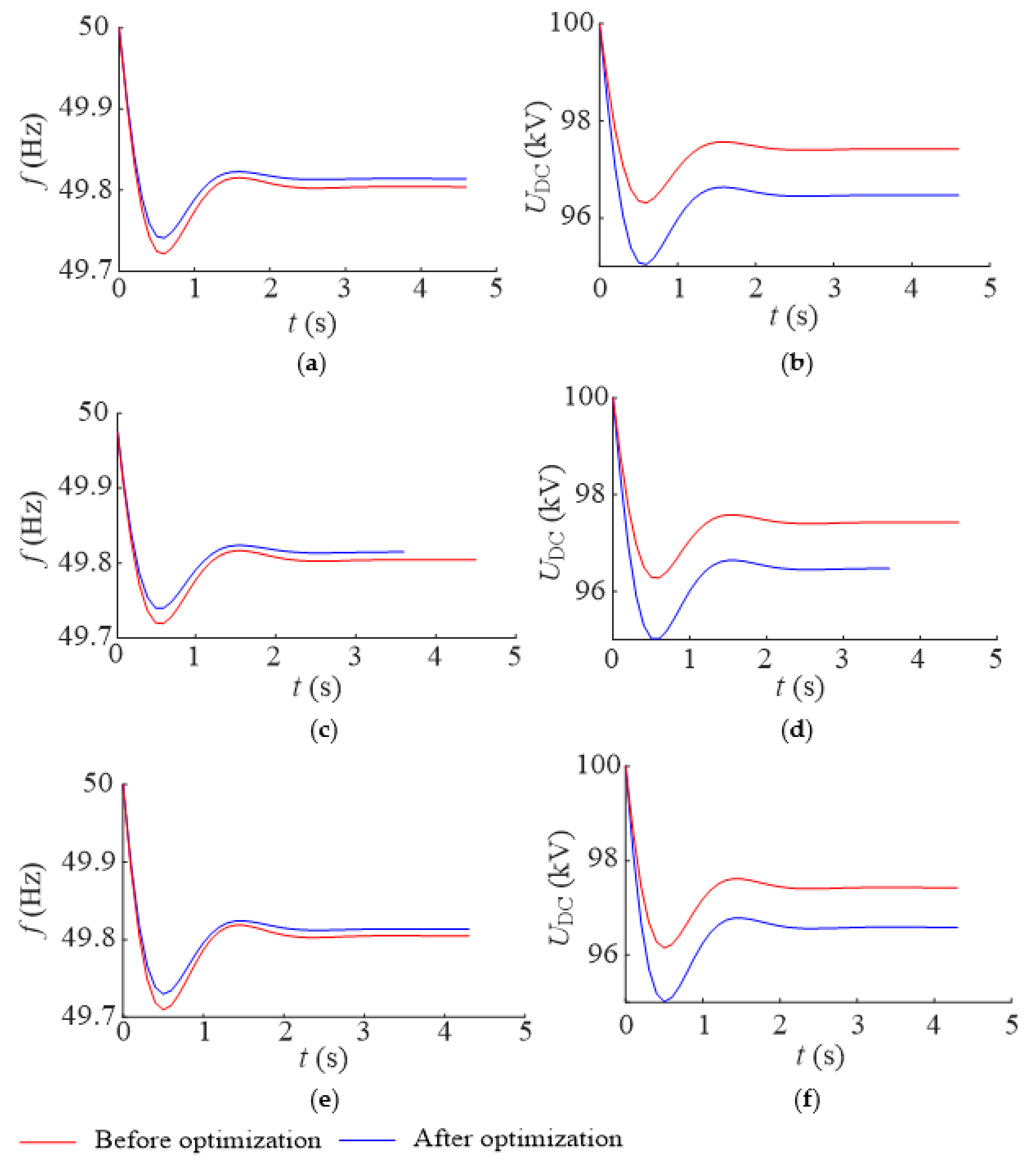
The steady state power flows before and after the optimization of HDC are given in Table 3. The increased inertia provided by the VSC-HVDC with the optimized HDC based on the improved DPF model is validated as shown in Figure 9.
With the optimized HDC, the inertia provided by the VSC-HVDC is further enhanced, thus the transient drop rate of the system frequency is reduced (see Figure 9a,c,e). The maximum UDC approaches the constraint, showing that the stored energy in the DC capacitor is fully utilized to prevent frequency drop (see Figure 9b,d,f)). The larger deviation of the DC voltage leads to more output of the DFIG (see Table 3), and less deviation of the steady-state frequency. The above conclusions are validated under different ranges of the wind speed.
8. Conclusions
For the DFIGs integrated through the VSC-HVDC, the cascaded droop control is introduced to the DPF model for the coordinated regulation with the inertia of the VSC-HVDC and the DFIG, and the primary regulation of the SG and the DFIG, where the SGs’ output considers the governor delay, the inertia of the VSC-HVDC follows the DC voltage constraint, and the inertia of the DFIG changes with the kinetic energy.
Some conclusions are yielded as follows:
- (1)
- Ignorance of the governor delay of the SGs yields an optimistic estimation of the frequency oscillation and nadir. With the governor delay, the frequency nadir occurs at the early stage of the frequency regulation due to not being fully supportive of the SGs. With the larger delay, a longer time is needed to reach the steady state frequency.
- (2)
- With the virtual inertia control of VSC-HVDC, releasing the stored energy in the DC capacitor reduces the drop rate of the frequency at the early stage of regulation. Initialization of HDC based on estimation of the frequency nadir provides more inertia support to the system frequency without violating the constraint of the DC voltage.
- (3)
- With the DFIG participating in frequency regulation through the VSC-HVDC, the transient drop rate and the steady-state deviation of frequency are further reduced. The rotor speed and kinetic energy of the DFIG vary during the frequency regulation, thus the equivalent inertia needed to be modified accordingly.
- (4)
- Optimization of HDC based on the improved DPF model maximizes the virtual inertia of the VSC-HVDC for a better frequency regulation effect.
Author Contributions
Conceptualization, T.S.; Data curation, J.H.; Formal analysis, J.H.; Funding acquisition, T.S.; Investigation, T.S.; Methodology, T.S.; Project administration, J.H.; Software, T.S.; Validation, J.H.; Writing-original draft, T.S.; Writing-review and editing, J.H. All authors have read and agreed to the published version of the manuscript.
Funding
This research was funded by the Nantong Science and Technology Plan Project, grant number JC2021107.
Institutional Review Board Statement
Not applicable.
Informed Consent Statement
Not applicable.
Data Availability Statement
Not applicable.
Conflicts of Interest
The authors declare no conflict of interest.
References
- Qiu, S.; Chunju, F.; Cheng, L.; Linyue, Q. Research on VSC–HVDC control strategy based on large offshore wind power system. J. Eng. 2017, 2017, 1923–1927. [Google Scholar] [CrossRef]
- Li, Y.; Liu, C.; Tian, X.; Wang, Z. Study on fault ride-through control of islanded wind farm connected to VSC-HVDC grid based on the VSC converter AC-side bus forced short circuit. J. Eng. 2019, 2019, 3325–3328. [Google Scholar] [CrossRef]
- Farsani, P.M.; Vennelaganti, S.G.; Chaudhuri, N.R. Synchrophasor-enabled power grid restoration with DFIG-based wind farms and VSC-HVDC transmission system. IET Gener. Transm. Distrib. 2018, 12, 1339–1345. [Google Scholar] [CrossRef]
- Elliott, D.; Bell, K.; Finney, S.J.; Adapa, R.; Brozio, C.; Yu, J.; Hussain, K. A Comparison of AC and HVDC Options for the Connection of Offshore Wind Generation in Great Britain. IEEE Trans. Power Deliv. 2015, 31, 798–809. [Google Scholar] [CrossRef] [Green Version]
- Rouzbehi, K.; Zhang, W.; Candela, J.I.; Luna, A.; Rodriguez, P. Unified reference controller for flexible primary control and inertia sharing in multi-terminal voltage source converter-HVDC grids. IET Gener. Transm. Distrib. 2017, 11, 750–758. [Google Scholar] [CrossRef] [Green Version]
- Miao, Z.; Fan, L.; Osborn, D.; Yuvarajan, S. Wind Farms with HVdc Delivery in Inertial Response and Primary Frequency Control. IEEE Trans. Energy Convers. 2010, 25, 1171–1178. [Google Scholar] [CrossRef]
- Zhao, J.; Lyu, X.; Fu, Y.; Hu, X.; Li, F. Coordinated Microgrid Frequency Regulation Based on DFIG Variable Coefficient Using Virtual Inertia and Primary Frequency Control. IEEE Trans. Energy Convers. 2016, 31, 833–845. [Google Scholar] [CrossRef]
- Vyver, J.V.D.; Kooning, J.D.M.D.; Meersman, B.; Vandevelde, L.; Vandoorn, T.L. Droop control as an alternative inertial response strategy for the synthetic inertia on wind turbines. IEEE Trans. Power Syst. 2016, 31, 1129–1138. [Google Scholar] [CrossRef]
- Ye, H.; Pei, W.; Qi, Z. Analytical Modeling of Inertial and Droop Responses From a Wind Farm for Short-Term Frequency Regulation in Power Systems. IEEE Trans. Power Syst. 2015, 31, 3414–3423. [Google Scholar] [CrossRef]
- Arani, M.F.M.; Mohamed, Y.A.-R.I. Dynamic Droop Control for Wind Turbines Participating in Primary Frequency Regulation in Microgrids. IEEE Trans. Smart Grid 2017, 9, 5742–5751. [Google Scholar] [CrossRef]
- Lee, J.; Muljadi, E.; Sørensen, P.E.; Kang, Y.C. Releasable Kinetic Energy-Based Inertial Control of a DFIG Wind Power Plant. IEEE Trans. Sustain. Energy 2016, 7, 279–288. [Google Scholar] [CrossRef]
- Li, Y.; Xu, Z.; Østergaard, J.; Hill, D. Coordinated Control Strategies for Offshore Wind Farm Integration via VSC-HVDC for System Frequency Support. IEEE Trans. Energy Convers. 2017, 32, 843–856. [Google Scholar] [CrossRef] [Green Version]
- Zhu, J.; Booth, C.; Adam, G.P.; Roscoe, A.; Bright, C.G. Inertia Emulation Control Strategy for VSC-HVDC Transmission Systems. IEEE Trans. Power Syst. 2012, 28, 1277–1287. [Google Scholar] [CrossRef] [Green Version]
- Zhu, J.; Guerrero, J.M.; Hung, W.; Booth, C.D.; Adam, G.P. Generic inertia emulation controller for multi-terminal voltage-source-converter high voltage direct current systems. IET Renew. Power Gener. 2014, 8, 740–748. [Google Scholar] [CrossRef] [Green Version]
- Liu, H.; Chen, Z. Contribution of VSC-HVDC to Frequency Regulation of Power Systems with Offshore Wind Generation. IEEE Trans. Energy Convers. 2015, 30, 918–926. [Google Scholar] [CrossRef]
- Adeuyi, O.D.; Cheah-Mane, M.; Liang, J.; Jenkins, N. Fast Frequency Response from Offshore Multiterminal VSC–HVDC Schemes. IEEE Trans. Power Deliv. 2016, 32, 2442–2452. [Google Scholar] [CrossRef] [Green Version]
- Silva, B.; Moreira, C.L.; Seca, L.; Phulpin, Y.; Lopes, J.A.P. Provision of inertial and primary frequency control services using offshore multi-terminal HVDC networks. IEEE Trans. Sustain. Energy 2012, 3, 800–808. [Google Scholar] [CrossRef]
- Chan, M.L.; Dunlop, R.D.; Schweppe, F. Dynamic Equivalents for Average System Frequency Behavior Following Major Distribances. IEEE Trans. Power Appar. Syst. 1972, PAS-91, 1637–1642. [Google Scholar] [CrossRef]
- Wang, R.; Zhang, H.; Li, C.; Ma, C. Dynamic power flow calculation method of power system with wind power. In Proceedings of the International Conference on Electric Utility Deregulation and Restructuring and Power Technologies (DRPT), Changsha, China, 26–29 November 2015. [Google Scholar] [CrossRef]
- Ramanathan, R.; Ramchandani, H.; Sackett, S.A. Dynamic Load Flow Technique for Power System Simulators. IEEE Trans. Power Syst. 1986, 1, 25–30. [Google Scholar] [CrossRef]
- Baojiang, X.; Haibo, Z. The research on distributed dynamic power flow based on asynchronous iteration mode considering frequency change. In Proceedings of the International Conference on Power System Technology, Hangzhou, China, 24–28 October 2010. [Google Scholar] [CrossRef]
- Akbari, M.; Madani, S.M. Analytical evaluation of control strategies for participation of doubly fed induction generator-based wind farms in power system short-term frequency regulation. IET Renew. Power Gener. 2014, 8, 324–333. [Google Scholar] [CrossRef]
- Wang, R.; Xie, Y.; Zhang, H.; Li, C.; Li, W.; Terzija, V. Dynamic power flow algorithm considering frequency regulation of wind power generators. IET Renew. Power Gener. 2017, 11, 1218–1225. [Google Scholar] [CrossRef]
- Shao, H.; Cai, X.; Zhou, D.; Li, Z.; Zheng, D.; Cao, Y.; Wang, Y.; Rao, F. Equivalent modeling and comprehensive evaluation of inertia emulation control strategy for DFIG wind turbine generator. IEEE Access 2019, 7, 64798–64811. [Google Scholar] [CrossRef]
- Tian, X.; Wang, W.; Chi, Y.; Li, Y.; Liu, C. Virtual inertia optimisation control of DFIG and assessment of equivalent inertia time constant of power grid. IET Renew. Power Gener. 2018, 12, 1733–1740. [Google Scholar] [CrossRef]
- Li, S.; Zhang, W.; Wang, Z. Improved dynamic power flow model with DFIGs participating in frequency regulation. Int. Trans. Electr. Energy Syst. 2017, 27, e2459. [Google Scholar] [CrossRef]
- Li, Y.; Zhang, Z.; Yang, Y.; Li, Y.; Chen, H.; Xu, Z. Coordinated control of wind farm and VSC–HVDC system using capacitor energy and kinetic energy to improve inertia level of power systems. Int. J. Electr. Power Energy Syst. 2014, 59, 79–92. [Google Scholar] [CrossRef]
- Wang, Y.; Wen, W.; Wang, C.; Liu, H.; Zhan, X.; Xiao, X. Adaptive voltage droop method of multiterminal VSC-HVDC systems for DC voltage deviation and power sharing. IEEE Trans. Power Deliv. 2019, 34, 169–176. [Google Scholar] [CrossRef]
- Chakrabarti, S.; Kyriakides, E. Optimal Placement of Phasor Measurement Units for Power System Observability. IEEE Trans. Power Syst. 2008, 23, 1433–1440. [Google Scholar] [CrossRef]
Figure 1.
First-order model of governor delay.
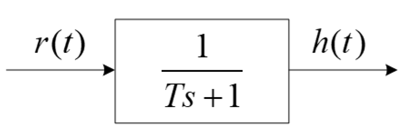
Figure 2.
Change of active power output target of SG at time steps of DPF model.

Figure 3.
Frequency regulation by DFIG integrated through VSC-HVDC.
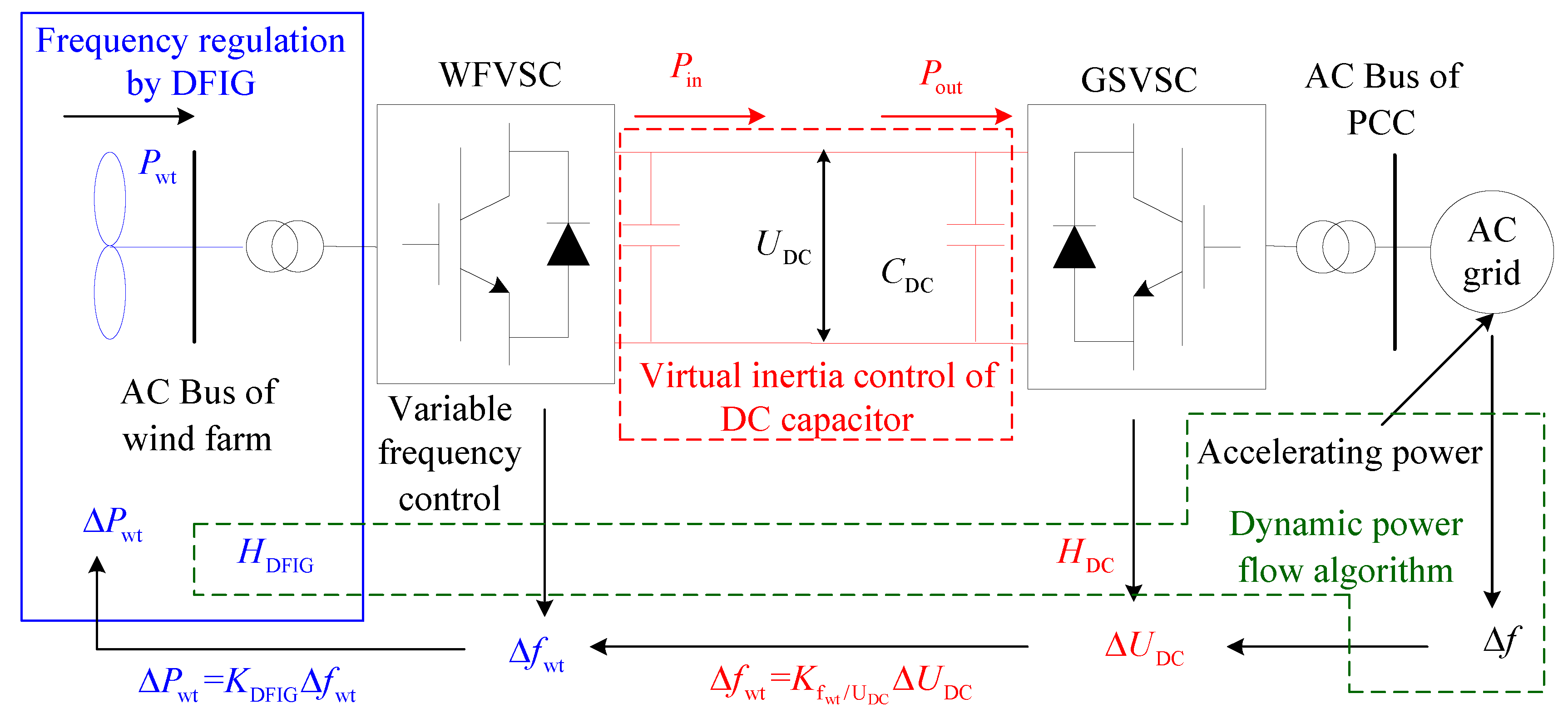
Figure 4.
Captured power versus rotating speed of WT.

Figure 5.
Improved DPF model with DFIG integrated through VSC-HVDC.
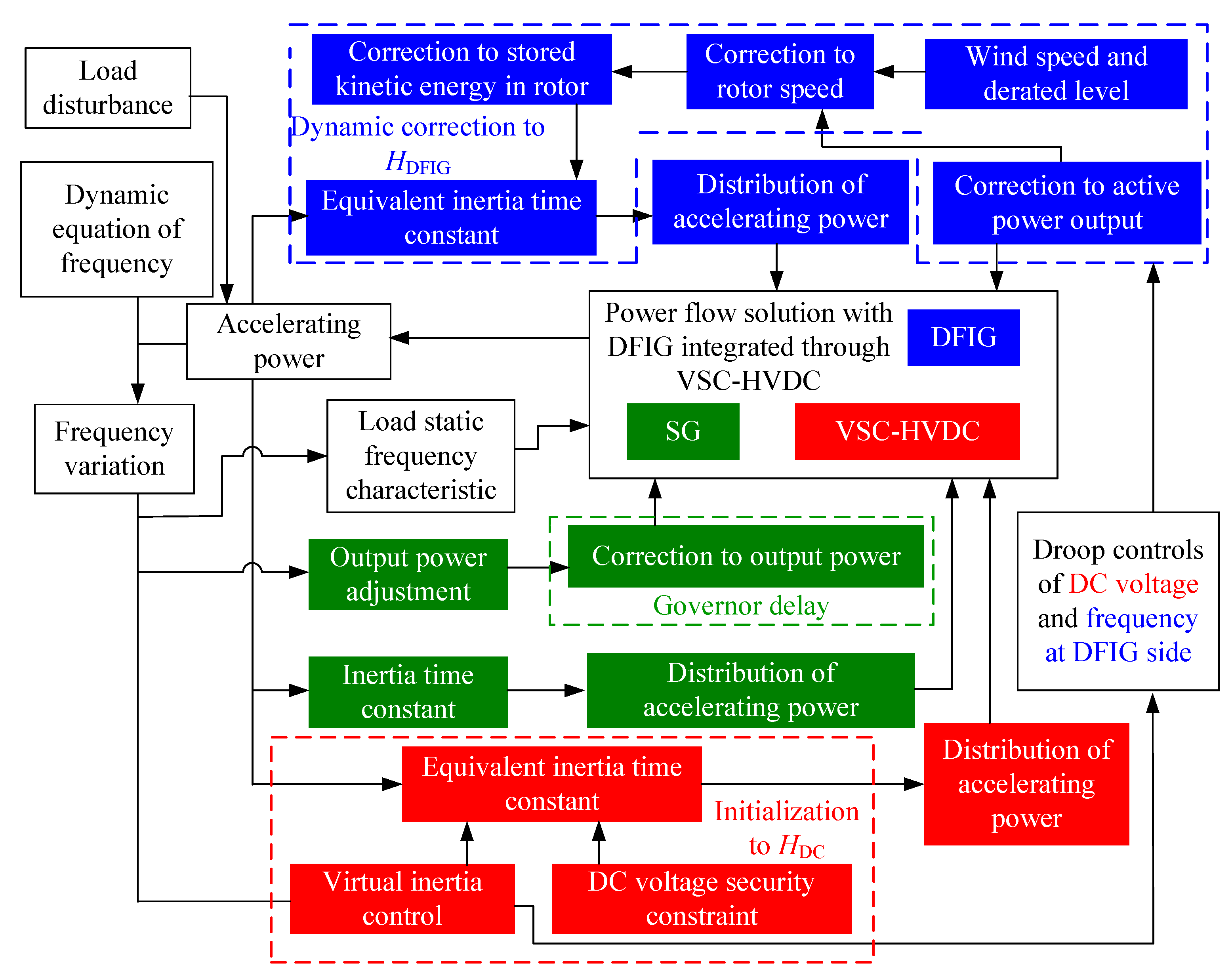
Figure 6.
Optimization to HDC using improved DPF model.
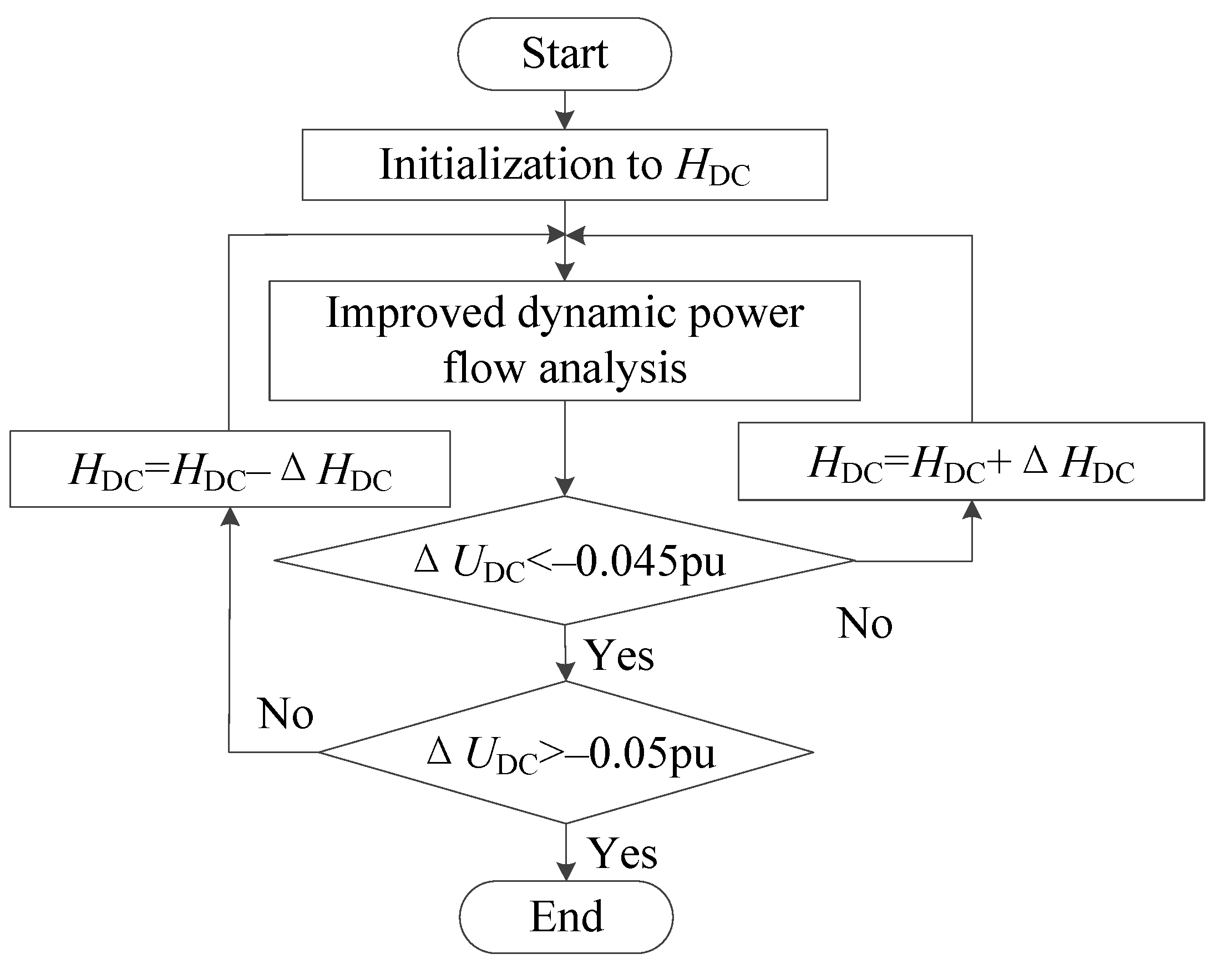
Figure 7.
Impact of virtual inertia control by VSC-HVDC on frequency regulation: (a) System frequency; (b) DC voltage.
Figure 7.
Impact of virtual inertia control by VSC-HVDC on frequency regulation: (a) System frequency; (b) DC voltage.
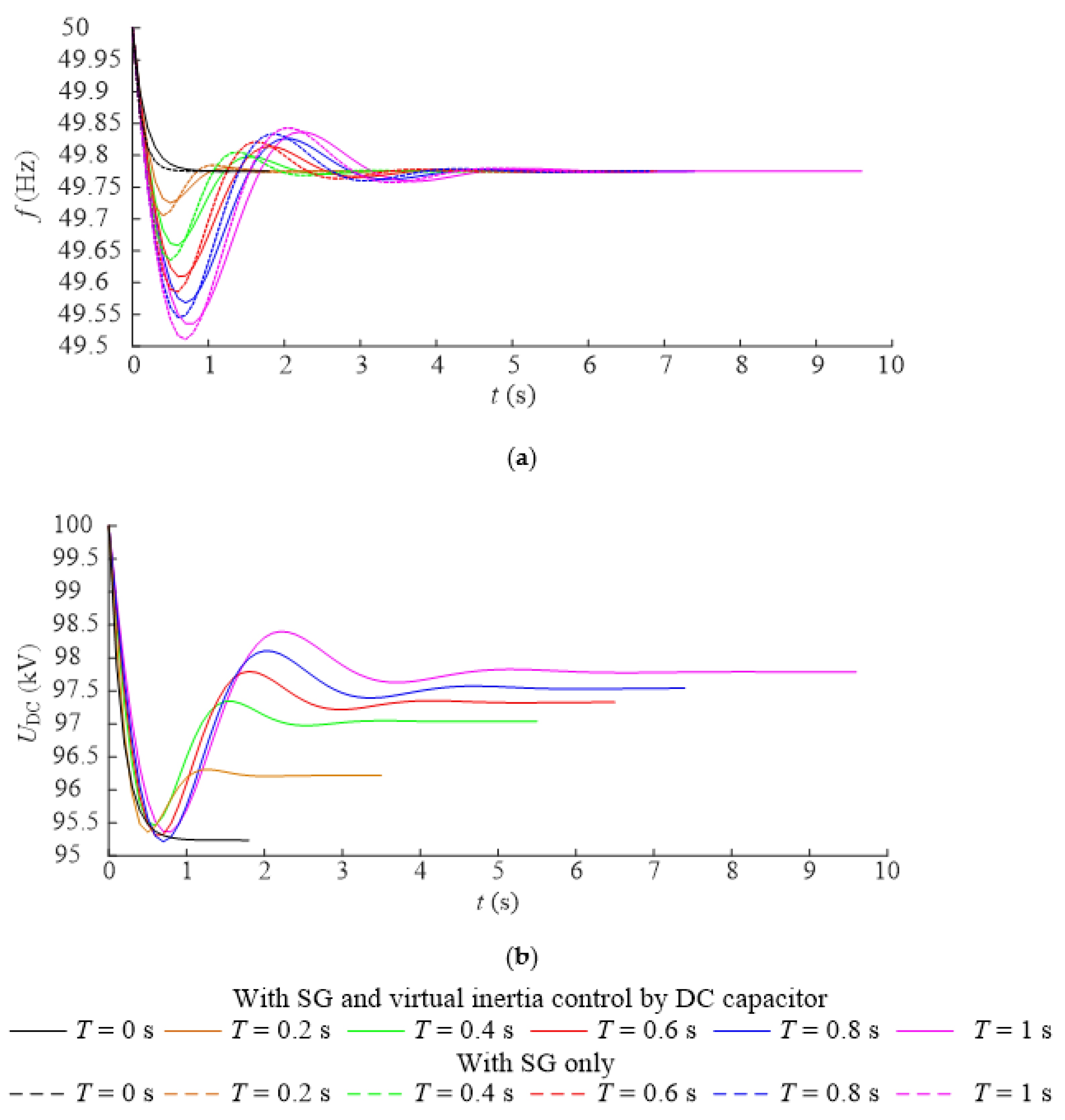
Figure 8.
DPFs under different wind speeds: (a) System frequency; (b) DC voltage; (c) Rotor speed of DFIG; (d) Captured power of WT; (e) Inertia of DFIG.
Figure 8.
DPFs under different wind speeds: (a) System frequency; (b) DC voltage; (c) Rotor speed of DFIG; (d) Captured power of WT; (e) Inertia of DFIG.

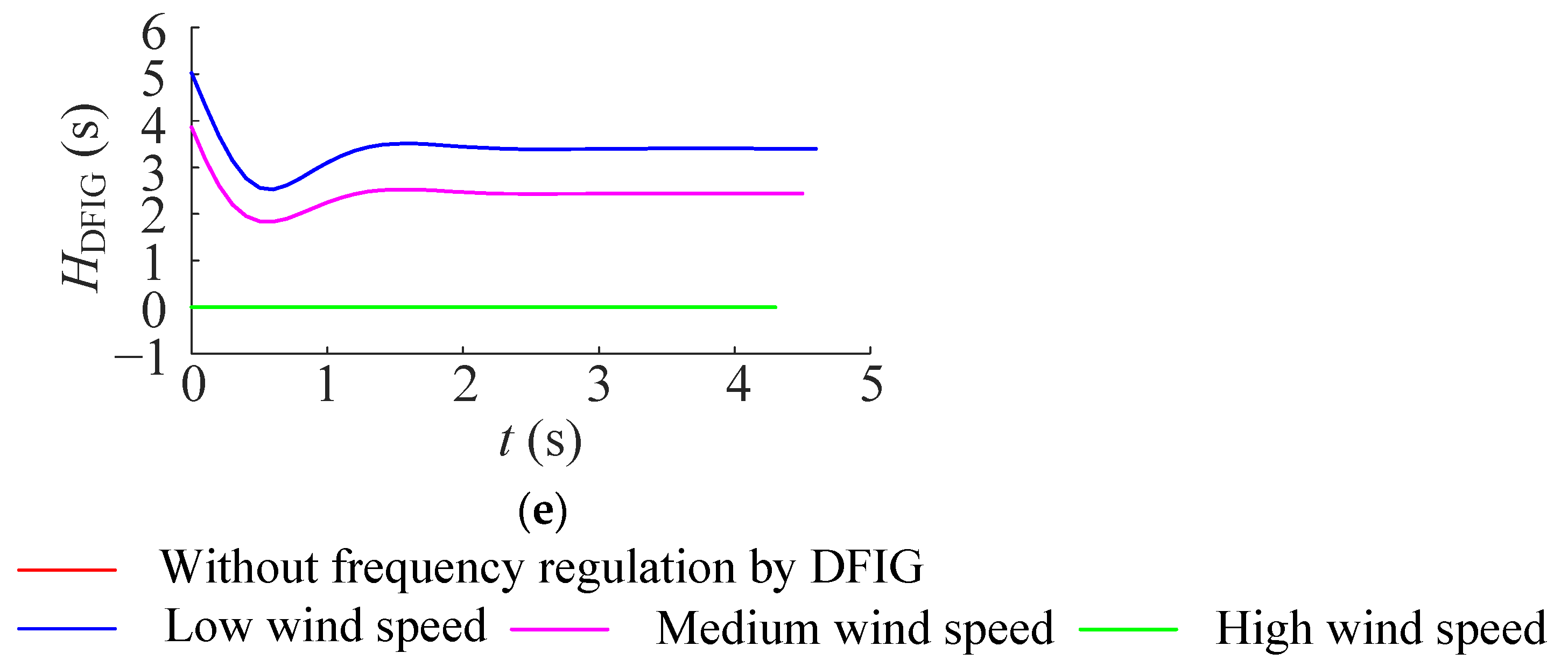
Figure 9.
Comparison of dynamic power flows before and after optimization of HDC: (a) System frequency under low wind speed; (b) DC voltage under low wind speed; (c) System frequency under medium wind speed; (d) DC voltage under medium wind speed; (e) DC voltage under high wind speed; (f) DC voltage under high wind speed.

Table 1.
Initialization of HDC considering governor delay.
| T (s) | 0 | 0.2 | 0.4 | 0.6 | 0.8 | 1 |
|---|---|---|---|---|---|---|
| Δfmax (p.u.) | –0.0042 | –0.0059 | –0.0075 | –0.0083 | –0.009 | –0.01 |
| HDC (s) | 3.10 | 2.47 | 1.95 | 1.76 | 1.62 | 1.46 |
Table 2.
Steady state power flows under different wind speeds before and after load disturbance.
| Parameter | Pwt (p.u.) | ΣPG (p.u.) | ΣPL (p.u.) | ΔPwt (p.u.) | |
|---|---|---|---|---|---|
| Wind Speed | |||||
| Low | Before | 0.5257 | 3.6804 | 4.1900 | 0.0646 |
| After | 0.5903 | 4.0725 | 4.6194 | ||
| Medium | Before | 0.7338 | 3.4678 | 4.1900 | 0.0645 |
| After | 0.7983 | 3.8593 | 4.6195 | ||
| High | Before | 1.2963 | 2.9085 | 4.1900 | 0.0643 |
| After | 1.3606 | 3.2987 | 4.1697 |
Table 3.
Steady state power flows under different wind speeds before and after optimization of HDC.
| Parameter | Pwt (p.u.) | ΣPG (p.u.) | ΣPL (p.u.) | |
|---|---|---|---|---|
| Wind Speed | ||||
| Low | Before | 0.5903 | 4.0725 | 4.6194 |
| After | 0.6140 | 4.0522 | 4.6231 | |
| Medium | Before | 0.7983 | 3.8593 | 4.6195 |
| After | 0.8219 | 3.8392 | 4.6232 | |
| High | Before | 1.3606 | 3.2987 | 4.1697 |
| After | 1.3816 | 3.2812 | 4.6229 |
Publisher’s Note: MDPI stays neutral with regard to jurisdictional claims in published maps and institutional affiliations. |
© 2022 by the authors. Licensee MDPI, Basel, Switzerland. This article is an open access article distributed under the terms and conditions of the Creative Commons Attribution (CC BY) license (https://creativecommons.org/licenses/by/4.0/).
Share and Cite
MDPI and ACS Style
Sun, T.; Huang, J. Improved Dynamic Power Flow Model with Frequency Regulation by DFIG Integrated through VSC-HVDC Considering Governor Delay of SG. Appl. Sci. 2022, 12, 5447. https://doi.org/10.3390/app12115447
AMA Style
Sun T, Huang J. Improved Dynamic Power Flow Model with Frequency Regulation by DFIG Integrated through VSC-HVDC Considering Governor Delay of SG. Applied Sciences. 2022; 12(11):5447. https://doi.org/10.3390/app12115447
Chicago/Turabian StyleSun, Tingting, and Jiejie Huang. 2022. "Improved Dynamic Power Flow Model with Frequency Regulation by DFIG Integrated through VSC-HVDC Considering Governor Delay of SG" Applied Sciences 12, no. 11: 5447. https://doi.org/10.3390/app12115447
Note that from the first issue of 2016, this journal uses article numbers instead of page numbers. See further details here.