
Hardware Development and Safety Control Strategy Design for a Mobile Rehabilitation Robot
by
 , ,
, ,
Lian-Wang Lee
1 ,
,
I-Hsum Li
2,
Liang-Yu Lu
3,
Yu-Bin Hsu
1,
Shean-Juinn Chiou
1 and
Te-Jen Su
4,5,* 1
Department of Mechanical Engineering, National Chung Hsing University, No. 145, Xingda Road, South District, Taichung City 40227, Taiwan
2
Department of Mechanical and Electro-Mechanical Engineering, Tamkang University, No. 151, Yingzhuan Road, Tamsui District, New Taipei City 25137, Taiwan
3
Department of Mechanical Engineering, National Sun Yat-sen University, No. 70, Lien-Hai Road, Kaohsiung City 80424, Taiwan
4
Department of Electronic Engineering, National Kaohsiung University of Science and Technology, No. 415, Jiangong Road, Sanmin District, Kaohsiung City 807618, Taiwan
5
Graduate Institute of Clinical Medicine, Kaohsiung Medical University, No. 100, Shih-Chuan 1st Road, Sanmin District, Kaohsiung City 80708, Taiwan
*
Author to whom correspondence should be addressed.
Appl. Sci. 2022, 12(12), 5979; https://doi.org/10.3390/app12125979
Submission received: 28 April 2022
/
Revised: 8 June 2022
/
Accepted: 9 June 2022
/
Published: 12 June 2022
(This article belongs to the Special Issue Human-Computer Interactions 2.0)
Abstract
:The use of bodyweight unloading force control on a treadmill with therapist manual assistance for gait training imposes constraints on natural walking. It influences the patient’s training effect for a full range of natural walks. This study presents a prototype and a safety controller for a mobile rehabilitation robot (MRR). The prototype integrates an autonomous mobile bodyweight support system (AMBSS) with a lower-limb exoskeleton system (LES) to simultaneously achieve natural over-ground gait training and motion relearning. Human-centered rehabilitation robots must guarantee the safety of patients in the presence of significant tracking errors. It is difficult for traditional stiff controllers to ensure safety and excellent tracking accuracy concurrently, because they cannot explicitly guarantee smooth, safe, and overdamped motions without overshoot. This paper integrated a linear extended state observer (LESO) into proxy-based sliding mode control (ILESO-PSMC) to overcome this problem. The LESO was used to observe the system’s unknown states and total disturbance simultaneously, ensuring that the “proxy” tracks the reference target accurately and avoids the unsafe control of the MRR. Based on the Lyapunov theorem to prove the closed-loop system stability, the proposed safety control strategy has three advantages: (1) it provides an accurate and safe control without worsening tracking performance during regular operation, (2) it guarantees safe recoveries and overdamped properties after abnormal events, and (3) it need not identify the system model and measure unknown system states as well as external disturbance, which is quite difficult for human–robot interaction (HRI) systems. The results demonstrate the feasibility of the proposed ILESO-PSMC for MRR. The experimental comparison also indicates better safety performance for the ILESO-PSMC than for the conventional proportional–integral–derivative (PID) control.
1. Introduction
In the past decade, with the continuous increase in the elderly population in developing and developed countries, the application of human-centered walking rehabilitation wearable robots has attracted increasing attention. Wearable robots are usually defined as mechanical devices that enhance a person’s locomotion and/or physical abilities. It can effectively combine human cognitive knowledge with the advantages of robotic devices to help users accomplish their desired activities. Orthoses and exoskeletons represent two prime examples of wearable robotics. They can be “worn” by the operator, fit snugly on the body, and work in harmony with the operator’s movements. The distinction between orthoses and exoskeletons is blurry. The term “exoskeleton” refers to systems, not just passive protection and support shells. Among these exoskeleton rehabilitation systems, wearable rehabilitation robots related to the lower limbs are an essential part, because the lower limbs of the human are one of the most critical parts in maintaining autonomy in life [1]. These exoskeleton rehabilitation devices drive subjects to repeatedly move their upper or lower limbs along a given trajectory. The control strategies combined with the assist-as-needed method enable the gait rehabilitation exoskeleton to improve its training efficiency [2]. Continuous passive motion (CPM) uses exoskeleton systems to substitute for physical therapists; it is an effective gait training method for treating limb spasticity and contractures [3]. The CPM can effectively improve the effectiveness of rehabilitation training [4]. The use of exoskeleton devices in the rehabilitation process enables precise, controlled, and long-term training. However, rigid exoskeletons still have issues such as safety, adaptability, and comfort that need to be overcome during the rehabilitation process. Therefore, the development of rehabilitation exoskeletons is gradually shifting towards soft exoskeletons [5,6]. Patients trained with robotic assistance combined with physical therapy have a better chance of walking independently than those who did not use mechanical aid [7]. Relative motion-based treadmill gait training systems, such as GaitTrainer [1], LOPES [8], ALEX [9], and Lokomat [10] are frequently integrated with the bodyweight support system (BSS) and lower limb exoskeletons to realize CPM. These systems use active, passive, and damping training modes to repeat high-intensity training. However, this kind of body-weight-supported treadmill gait rehabilitation is non-ecological training. Patients can only perform gait training at a controlled speed on the treadmill and cannot move freely. Therefore, posture, dynamic balance ability, and proprioception are not adequately trained in these devices. The bodyweight-supported treadmill gait rehabilitation requires that all patients receive the same gait training and does not satisfy the gait pattern of individual patients [1]. These drawbacks have resulted in an alternative approach to over-ground gait training.
Over-ground and treadmill walking differ with respect to joint kinematics, muscle activation, gait parameters, and body coordination [11]. Kim et al. showed that patients recover quickly if they frequently train in their daily environment [12]. Integrating a lower limb exoskeleton and a mobile robot can mimic a natural walk on the over-ground [13,14,15,16]. The integration of over-ground gait training with the function of obstacle avoidance provides balance exercises to users [17]. However, most current gait training systems must use a treadmill for training, although it cannot simulate a functional environment. Over-ground natural gait training systems (ONGS) allow patients to walk over-ground and give patients the confidence and ability to perform daily activities. A BSS is essential for the ONGS. The adjustable bodyweight unloading force of the BSS increases the complexity and intensity of gait training. However, few mobile-type BSSs are designed explicitly for over-ground natural gait training. Therefore, over-ground walking rehabilitation systems were developed [18,19,20,21] for lower-limb rehabilitation that allows patients to have higher freedom of locomotion. Liu et al. developed a gait training system, “NaTUre-gaits”, which comprises a mobile vehicle, a lower extremity exoskeleton, a BSS, and a pelvic adjustment mechanism [18]. The “Andago” robot consists of two units [19], a four-wheel mobile vehicle and an independent passive body support mechanism. However, Andago does not have a lower extremity exoskeleton to aid over-ground gait training. Seo et al. developed a differentially steered mobile vehicle called “Where Robot”, which follows the subject’s motion and adjusts the subject’s center of gravity to reduce the bodyweight [20]. Stauffer et al. developed the “WalkTrainer”, which applies a lower-extremity exoskeleton to control motion for the subject’s hip and knee, allowing people with paraplegia to walk on the ground [21]. However, the systems mentioned above still present several drawbacks. For example, these mobile platforms cannot perform functions of obstacle avoidance and navigation and cannot walk along ground corridors. In addition, in this training type, the lower limbs of the patient must be tightly connected to the robotic system for rehabilitation training. However, the conventional position controller, i.e., the proportional–integral–derivative (PID) one, widely used in limb rehabilitation systems, cannot adequately guarantee safety during the training. Therefore, an MRR prototype was developed in this study for passive over-ground gait training and to present a safety controller to compensate for various uncertainties of MRR and external load disturbances, thus providing safety to the patient.
In addition to control accuracy, the control of human-centered limb rehabilitation robots also needs to focus on human safety and compliance. The patient may feel unsafe or may hurt themselves again if vibration or transient overshoot happen during the tracking response. Therefore, the controller of the rehabilitation robot needs to have over-damped characteristics to increase the shock resistance ability and avoid harmful situations occurring. With several differences among patients, such as weights, heights, and body appearance, the controller design needs to be capable of adapting to these variations. The design should be robust enough to overcome the uncertainties of human-centered limb rehabilitation robots. Generally, to guarantee control accuracy, the PID controller’s gain is usually set to be significant; the high-gain PID control may result in a large overshoot. When the PID controller’s gain is small, it exhibits a slow overdamped characteristic where a fast response cannot be ensured. On the other hand, large overshoots and oscillation may happen when the system encounters emergency events, e.g., sudden power outage, sensor faults, and accidental environmental contact. Therefore, in the conventional PID control method, it is challenging to simultaneously achieve both safety and work performance. Sliding mode control (SMC) can force the system state to be kept on the sliding-mode surface and converge to an equilibrium point in a finite time [22,23]. However, the chattering phenomenon during the convergence process deteriorates the safety performance. To ensure both the tracking accuracy and security of the controlled system, a proxy-based sliding mode control (PSMC) was first introduced by Ryo et al. [24], which combines the features of SMC and PID to guarantee closed-loop dynamic behavior continuously. It is an improved version of PID control and has been applied in the nonlinear control field by many researchers due to the simplicity of the control architecture [3,25,26]. PSMC is widely applied in soft robotics because of its superiority in ensuring safety and precision in motion [27,28]. It limits the control output strictly and combines overdamping to provide safe recovery from abnormal events with good tracking performance during regular operation [24,25,29,30]. Even though the original PSMC has been well applied in various systems, it still needs significant improvements in the theoretical analysis of stability. The original PSMC is a model-free controller, and its stability can be verified by a conjecture (see [24]); however, its theoretical proof has not been well addressed. Ref. [31] presented an extended PSMC strategy via the Lyapunov stability theorem to solve the problem of stability for the original PSMC. However, all system states and magnitudes of disturbances were assumed to be provided in the extended PSMC. However, in practical applications, it is impossible to obtain or measure all the states and disturbances of the system. Therefore, it is difficult to effectively apply extended PSMC to practical systems. To this end, this paper presents a novel safety control method that integrates linear extended state observer (LESO) combined with a proxy-based sliding mode control (ILESO-PSMC) for MRR. We used the new virtual coupling and LESO to design the ILESO-PSMC. LESO was used to estimate the system’s states and total disturbance by involving the theoretical model. The stability of the ILESO-PSMC strategy was systematically proved by applying the Lyapunov theorem. This methodology simplifies the proof of the system’s stability and makes the derivation simple. The experimental results show that the ILESO-PSMC enables the system to track the desired target in both overdamped and smooth mode.
The rest of this paper is organized as follows. Section 2 introduces the design, hardware configuration, and functions of MRR. Section 3 describes the dynamic models of the AMBSS and LES. The controller design and stability analysis are described in detail in Section 4. Section 5 presents experiments demonstrating the effectiveness of the proposed control strategy and the verification of the feasibility of MRR. Finally, the conclusions of this study are drawn in Section 6.
2. System Design for Mobile Rehabilitation Robot (MRR)
In this study, we present a novel compact MRR for over-ground natural gait rehabilitation for low muscle tone and disabled lower limb muscle. The overall design concept and the photos of the MRR are shown in Figure 1. The system prototype photo of MRR shown in Figure 1 was taken with healthy subjects wearing it. This MRR comprises a pair of lower-limb exoskeleton systems (LES) and an autonomous mobile bodyweight support system (AMBSS). MRR provides two kinds of assistance solutions, including (a) an AMBSS and (b) an AMBSS and LES. These two independent devices can work in unison. AMBSS is a differential drive vehicle whose movement speed is regulated according to the gait training cycle set by the LES. A LiDAR is located at the front of AMBS. The LiDAR can detect obstacles within an angular range of 240° at a distance of 4 m with a resolution of 0.36°. AMBS is designed with three user-facing ultrasonic sensors, each covering an angular range of 15°. As mentioned above, the sensor measures the distance between the user and AMBS and the feedback to the embedded system to keep a safe distance of 0.2–0.4 m. The participants’ weight, percentage of weight offload, gait training cycles, and data stored can be entered using the human user interface (HUI). Embedded systems enable the coordination of information from peripherals, such as LES, ultrasonic sensors, motors, linear actuators, and load cells. Two buttons on the AMB control the movement of the AMB. The left and right wheels of the AMBS are governed by the left and right armrest buttons, respectively. If both buttons are pressed at the same time, the AMBS will move forward according to the gait speed set by the LES. The emergency button is installed above the right armrest. When this button is pressed, the AMBS and LES stop immediately. The LES provides drive assistance for hip and knee joint movement. Its principal function is additional support for the subject’s lower limbs and provides extra torque to their joints. The LES also leads the swinging lower limb through a specified cycle time of joint trajectory and avoids flexing the lower limb in standing. The LES uses four brushless motors and four harmonic drives to track gait trajectory, including knee and hip joint motions in the sagittal plane. When a participant wears the LES, the harness, and grips the handles on the armrest, the AMBSS controls the static unloading force to the desired level. Subsequently, the MRR performs obstacle avoidance, man–machine safe distance maintenance, and dynamic weight unloading force control through AMBSS. Simultaneously, the LES guides the patient to walk in the environment according to the set gait training cycle. Allowing patients to wander around in the environment can avoid loss of adherence due to the boredom of walking on a static treadmill. Therefore, our MRR can provide “corrective, not simple repetition” training according to gait with different cycles because it allows gait training to be set with different gait cycles. The LES is a module in MRR; it provides actuated assistance to perform the extension and flexion of human hip and knee joints in the sagittal plane and implement the gait locomotion of the lower limb. It can also perform a prerecorded walking pattern while recording the angular position of four actuated joints (knees and hips). The LES can be adjusted with respect to width and height to match the user’s characteristics (1.55 m to 1.85 m for altitude and up to 120 kg for weight), covering more than 95% of the target population [13]. The limiter switches are designed for each joint of LES to limit the range of motion for safety. The LES is walking assistance that provides the patient with CPM of the natural gait on the over-ground; it can generate different cycles of gait training modes according to the gait trajectory of healthy people. The LES adopts a forced standing posture, which forces the knee and hip joints to be at 0 degrees, for the start, stop, and end motion during the gait trajectory. The AMBSS must support patients of similar size and weight to those allowed by the LES. To increase safety, the AMBSS uses a medical-grade harness (from the waist to the perineum) to take the weight of the user and the LES. This configuration increases the balance and stability of the lower body of the patient during gait training. The AMBSS allows users to walk around freely with reduced weight; it integrates with the LES and also serves as the carrier of the controller, power source, and any other MRR electronic components. It is actuated by DC 24 V motors and linear actuators to perform the functions of obstacle avoidance navigation and dynamic bodyweight unloading. The AMBSS has a wheeled base with two frontal driving wheels and uses two DC motors to drive two active wheels and uses two passive universal wheels to maintain balance. Each active wheel is independently controlled. Therefore, it can move following a straight or curved path. The maximum speed of AMBSS is designed to be 0.7 m/s, in which the operating speed of AMBSS can be set to be consistent with LES at 0.2–0.5 m/s according to the gait cycle requirements of rehabilitation. The embedded system is used to implement the control algorithm and signal processing. The software of AMBSS runs in a real-time environment on an embedded system and is programmed using LabVIEW.
To match the propulsion speed of AMBSS with LES, it is important to measure the distance between the patient and the AMBSS. The AMBSS uses three ultrasound sensors to measure the distance between the user and the AMBSS, and each sensor covers an angular range of 15 degrees with a resolution of 0.3 cm. The ultrasound sensors are placed in the middle of the central crossbar, pointing to the user’s waist. The measured distances are sent as feedback to the embedded system to regulate the AMBSS speed. AMBSS acts as a slave subsystem to the LES (master), adapting the AMBSS’s speed to the user’s pace and maintaining a safe distance of 200–400 mm. A webcam mounted in front of the AMBSS captures the front view. The AMBSS exchanges messages with a human user interface (HUI) over Wi-Fi. A LIDAR is set in front of the AMBSS. It detects objects within 4000 mm with an angular range of 240° and a resolution of 0.36°. Besides the automatic obstacle avoidance navigation mode, AMBSS can also be controlled by two buttons on the armrest; the button on the right handle controls the right wheel motor, and the button on the left handle controls the left wheel motor. Simultaneously pressing both buttons, the AMBSS continuously moves forward at a set speed. When the emergency button is pressed, the AMBSS stops immediately. The LES can be removed from the AMBSS, resulting in a more gradual bodyweight unloading and greater freedom of possible locomotion. The AMBSS can support up to 40% of the user’s weight. For MRR operations, communication is performed through connections to an embedded system. The control system for the two modules (LES and AMBSS) was developed separately. The AMBSS moves according to the gait speed set by the LES and uses ultrasonic sensors to measure the user’s distance to achieve collaborative control between the LES and AMBSS [4,11]. The MRR defines three possible regions within the acceptable range of 0 to 600 mm (near 300 mm, optimal 400 mm, and far 500 mm). The MRR-provided human–machine interface allows the users to input the desired bodyweight unloading percentage and gait cycle. AMMBS can control the patient’s level of bodyweight unloading during gait training. The modular architecture of the developed system allows the implementation and validation of the control strategy on the system with ease.
3. Dynamic Models
Figure 1 depicts a drawing of the structural design of the MRR, comprising an AMBSS, an LES, and an embedded control system. AMBSS is a typical force-control-based linear actuator drive system, and LES is an electromechanical position control system comprising motors and gears.
3.1. The Dynamic Model of the Lower-Limb Exoskeleton
Since the main rotation of the lower limb joints occurs in the sagittal plane during the gait cycle, the hip and knee joints designed for LES only involve extension and flexion in the sagittal plane. The ankle joint is not actuated, which allows flexion and extension without restriction in the sagittal plane. The LES physically and firmly connects to the human legs; therefore, the kinematics of the LES can be represented as the kinematics of the human lower limb. The LES is designed as a two-link and symmetrical structure, such that when using the Lagrange formulation, its generic dynamic mode for a unilateral LES can be represented as follows [32]:
where is the vector of joint angle, and are the velocity and acceleration of the joint angle vector, is the inertial matrix of the human limb, represents the vector of the Coriolis and centrifugal matrix of the human limb, and is the vector of the gravitational torques of the human limb. is the external torque representing the human joint torque and the torque generated by the exoskeleton. The elements of the matrices and in Equation (1) were discussed in previous publications [33]. LES is a two-leg structure with each leg having two joints (knee and hip), and can be treated as four single-input-single-output (SISO) independent control systems with mechanical coupling disturbances. It is difficult to obtain the inertia matrix for the LES because the LES has variable thigh and shank structures, so the joint dynamics is derived from the moment balance equation in this paper. For example, considering the joint dynamics can be obtained by fixing the thigh link first and controlling the motor to rotate the knee joint in a uniform circular motion, the dynamic for the knee joint can be represented as:
where is the knee joint angle of the limb in the sagittal plane, is the sum of and , represented as the inertia of the low limb/exoskeleton, is the sum of and , represented as the viscous friction parameters of the low limb joint/exoskeleton, is the total of the torques generated by the human muscles and the exoskeleton actuator, is a portion of the torque that includes the gravitational torque of the low limb/exoskeleton, the torque caused by the other body segments, and the extra forces.
In this study, the knee and hip joints of the LES were actuated by flat brushless motors with a planetary reducer to perform gait locomotion. Through appropriately applied current field-oriented control [34], the electromagnetic torque can be simplified as
where is the torque constant and is the control current. Substituting (3) into (2), we can rewrite the knee joint servo drive system of LE in the following form:
where and is the control effort. Here, is defined as the state vector. The state space form for a joint of the LES can be represented as a 2nd-order general nonlinear system:
3.2. The Dynamic Model of AMBSS
The medical harness is used to connect the AMBSS frame to the waist of the human body and can be mathematically modeled as a mass-spring-damping model. From the viewpoint of dynamics, the AMBSS shown in Figure 1 can be approximately modeled as depicted in Figure 2. The center of gravity trajectory in the vertical direction of the sagittal plane can be expressed as a general function of time during gait training on the MRR. Let be the total vertical reaction force exerted on the human foot by the left and right soles and be the body acceleration in the vertical direction; then, the dynamics equation for the AMBSS can be represented as:
where is the mass of the human body, and denote the damping coefficient and stiffness of the human body, is the original position of the center of gravity in the vertical direction of the sagittal plane, g is the gravity acceleration, is the total vertical reaction force exerted to the human foot by the left and right soles, and is the support force provided by the AMBSS to the human in the vertical direction.
In this study, a linear actuator comprising a ball screw and a DC motor is used to lift the AMBSS mechanism. The linear actuator used by AMBSS is a one-dimensional device; therefore, the force control target was simplified to:
where is the expected reduction in the weight. Substituting (7) into (6) yields:
where is the mass of the AMBSS unilateral mechanism, is the force provided by the DC motors, , is the height on either side of the AMBSS, is the horizontal distance from the two support columns on both sides of the human body center. According to an earlier study [35], the dynamic equations of a DC motor can be expressed as:
where is the applied voltage, w is the angular velocity, is the current flowing through the windings, represents the actuator circuit inductance, is the total armature circuit resistance, is the electrical constant, is a proportionality constant of torque and is the electromagnetic torque of the motor. Concerning the external torque from a payload, the mechanical behavior is further obtained as:
where is the rotor moment of inertia and is the frictional coefficient. The objective of AMBSS is to keep the unloading force precise and provide feedback on the measured unloading force. Therefore, if the unloading force required for AMBSS is fpc, the torque for the unilateral payload is provided as:
where is the length of the ball screw lead. Generally, linear actuators are used for load torque control to reduce the angular velocity as the load torque increases. Therefore, the relationship of the linear actuator between the motor speed and the load output force can be expressed by the following Equation [36]:
where is the relationship coefficient between motor speed and output force, is the motor output force, and is the no-load speed. Substituting Equations (10)–(12) into Equation (9) and defining as the state vector, the state-space form of the AMBSS as a 2nd-order general nonlinear system can be derived as:
where and , respectively, denote the input and output of the AMBSS, and are nonlinear functions, is the lumped effect from unmodeled dynamics, model uncertainties and unknown external disturbances.
4. Dynamic Models
As mentioned above, both LES and AMBSS can be represented as a standard SISO second-order nonlinear system, as shown in Equations (5) and (13). In this section, we intend to develop an LESO and a PSMC for a SISO second-order nonlinear system and determine its stability for LES and AMBSS. A standard SISO second-order nonlinear system can be represented as:
where is the system state vector, is the control input signal, is the system output, is the nonlinear dynamic, is the control gain and is the lumped disturbance containing the external disturbances and model uncertainties.
4.1. Linear Extended State Observer Design
In practical applications, model disturbances and uncertainties are unavoidable in practical applications but usually cannot be measured directly; this degrades the control performance of the system. In this study, a linear extended-state observer (LESO), first presented previously [37], was introduced to estimate the system’s uncertainties, variable states and the unmodeled dynamics from measurable variables. The LESO regards all factors affecting the system, including nonlinearities, uncertainties, and disturbances that needed to be observed as a total uncertainty (i.e., extended state) [37]. Involving the extended state has the advantages of relative independence of the mathematical model of the plant, better performance, and simplified implementation. For Equation (14), assuming that is the nominal value of and is the associated uncertainties, we can have:
If the total uncertainty that needs to be estimated is defined as
and the extended state of LESO is chosen as the term of , the SISO second-order nonlinear system (14) can be extended and be rewritten as
where is the rate of change of the uncertainty. Equation (17) shows that all the uncertainties, including modeling errors and external disturbances, are lumped into the single term .
Assumption 1
([38]). The total uncertainty is continuously differentiable for the SISO second-order nonlinear system (14) and the inequality of
is satisfied, where
is a positive constant.
A vector form of the extended-order system (17) can be represented as (18) by defining as the extended state vector.
where We can design the LESO for the extended-order system (17) as:
where represents the observed state vector of LESO, is the gain matrix of the designed observer. Usually, the observer-gained is solvable through the pole placement method. For simplicity in the observer design, however, we selected the observer gain according to the required bandwidth of the observer, represented as
where should be larger than zero and is the only tuning parameter for the LESO. In general, the larger the observer bandwidth is, the more accurate the estimation is. However, the large observer bandwidth increases noise sensitivity. Therefore, the observer bandwidth must be properly selected as a compromise between the tracking performance and the noise tolerance [39].
Lemma 1
([40]). Assuming that the observer gain matrix in (19) is chosen such that
is a Hurwitz matrix, then the observer error
of the LESO for extended-order system (17) is bound for any bound .
According to Lemma 1, the estimation error of will converge to zero as such that . That is, the total disturbance can be estimated by the LESO, as described earlier (19) [41]. The general proofs of LESO stability [42] and its convergence [43] are then provided.
Remark 1.
The LESO in (19) estimates unknown states, including disturbances, as the inputs and outputs are provided. It is not restricted by a specific model of the controlled system. The LESO then estimates the controlled system’s states and total disturbance.
4.2. Integration of LESO within PSMC
Most previous work has proved that PSMC can passively compensate for disturbance in a closed-loop control dynamic. However, the stability of PSMC has not been well addressed. This paper proposes the integration of LESO within PSMC to estimate the system’s states and total disturbance and to provide stable tracking control. We provide a straightforward and simple proof of stability for the dynamic system. Figure 3 illustrates the principle of the physical model of ILESO-PSMC. In ILESO-PSMC, a virtual object, a “proxy”, is assumed to be connected to a physical actuator. Before proceeding to the ILESO-PSMC design, we first define the following sliding manifolds:
and
where is a positive constant, is the desired trajectory, and is the proxy output and the actuator output, respectively. It is difficult to directly measure the state, disturbance, and uncertainty of the actual system; Equation (22) is modified by the idea of the LESO, as follows:
where is the estimate of . It is noted that Equation (23) presents the tracking states of the proxy and the actuator. In Figure 3, the PD-type virtual coupling could drive the states of the actuator to the states of the proxy, and the ILESO-PSMC generated the force exerted on the proxy, as follows:
where is the total uncertainty estimated by the LESO, denotes the proxy mass, and are constants representing the proportional and differential gains, , and is the signum function. The virtual coupling is represented as:
Please note that the proposed virtual coupling force is not a pure PD-type controller. Because the force acts directly on the controlled actuator and its reaction force acts on the proxy, the following equation of motion is obtained based on Newton’s second law of motion:
Since the proxy is a virtual object and its mass is 0, Equation (26) can be expressed as:
where Substituting Equation (27) into Equation (25), the ILESO-PSMC can be applied to the actual actuator as:
4.3. Stability Analysis
The stability of the proposed controller, ILESO-PSMC, is analyzed in this section. For convenience of presentation, we first define the system’s equilibrium point as .
Remark 2.
The controllers (24) and (28) are designed based on the PSMC method and LESO technology. The primary difference between the ILESO-PSMC and traditional PSMC methods is that the states and total disturbance estimations are introduced in the control law to compensate for unmodeled dynamics, disturbances, and uncertainties. The ILESO-PSMC can deal with the problem that the system states cannot directly measure.
Remark 3.
The ILESO-PSMC (24) and (28) are functions of the LESO’s outputs Since the inputs of LESO are (or ) and , the proposed ILESO-PSMC only requires the output of the SISO second-order nonlinear system (14).
Theorem 1.
For the SISO second-order nonlinear system (14) in which the total uncertainty is bound (based on Assumption 1), if the observer gain matrix
in (19) is selected such that the matrix is Hurwitz, the system output asymptotically converges to the equilibrium point of the system using the proposed ILESO-PSMC scheme (24) and (28).
Proof.
To simplify the analysis, we only analyze the stability of the sliding surface in this section. The proof of stability of the sliding surface can also be found using the same outcome as follows. The Lyapunov function candidate for the sliding surface is defined as:
Obviously, the conditions of
are satisfied. By differentiating both sides of and substituting (21), (22), and (26) into , the derivation of the Lyapunov function candidate is obtained as:
We know from (30) and (31) that is a positive definite function and is a negative semi-definite function. Because is Hurwitz and the total uncertainty is bounded (based on Assumption 1), the estimate states as . Therefore, the system’s stability around the equilibrium is proven in the sense of Lyapunov. □
5. Experimental Validation
In this section, we describe the experiments performed to demonstrate the effectiveness of the developed MRR and ILESO-PSMC strategy. We planned the three experiments to verify the usability of the designed MRR. The first experiment tested the control effect of AMBSS on body weight support under static and dynamic situations. In this experiment project, the linear actuators of the two ILESO-PSMCs were adjusted on both sides to maintain the desired body weight support force. In the second experiment, four ILESO-PSMCs were used to respectively regulate the two knee joints and two hip joints to examine the LES’s effectiveness and control effect. We executed the third experiment to verify the usability of MRR for over-ground gait training and the efficacy of the ILESO-PSMC control methodology. The ILESO-PSMCs adopted in the three experiments were coded in National Instruments’ LabVIEW environment and implemented in an embedded system for real-time control. The gait training parameters used were input using the HUI and are listed as: (1) percentage unloading for the AMBSS, (2) body weight, and (3) moving speed of the MRR. While the subject was wearing the LES and the harness, the MRR adopted AMBSS to control the body weight support to the target value. After that, the user held the handles on the armrest to determine body balance in cases, where the user is wearing the LES and harness and holding the handles on the armrest. Subsequently, the MRR moved at the preset speed and maintained the dynamic unloading force to achieve over-ground gait training.
5.1. Experiment Setup
The MRR experimental system consists of an AMBSS, an LES, a control box, and a panel PC shown in Figure 4. A real-time embedded system (myRIO-1900 (National Instruments, Austin, TX, America)), an industrial touchscreen computer (Intel® Core TM i Celeron®, 3.1 GHz), direct-current servo motor modules, LiDAR, and a power supply module are installed inside the control box. The power supply can output 5 V, 10 V, 12 V, and 24 V voltage. Actuator control commands and sensor measurement signals can be transmitted through the D/A port and I/O ports on the real-time embedded system myRIO-1900. The LES is attached to the lower limb of the subject. The sampling interval of the controllers is 0.005 s.
5.2. Unloading Force Control of AMBSS
For AMBSS’s linear actuator controller design, the adjusted force must be smooth and slow to ensure a comfortable and safe interaction between the device and the subject. Therefore, the fifth-degree polynomial function describes the supporting load trajectory. The initial [i.e., and ] and final [i.e., and ] variations achieved were set as 0. The fifth-degree polynomial function is present as follows:
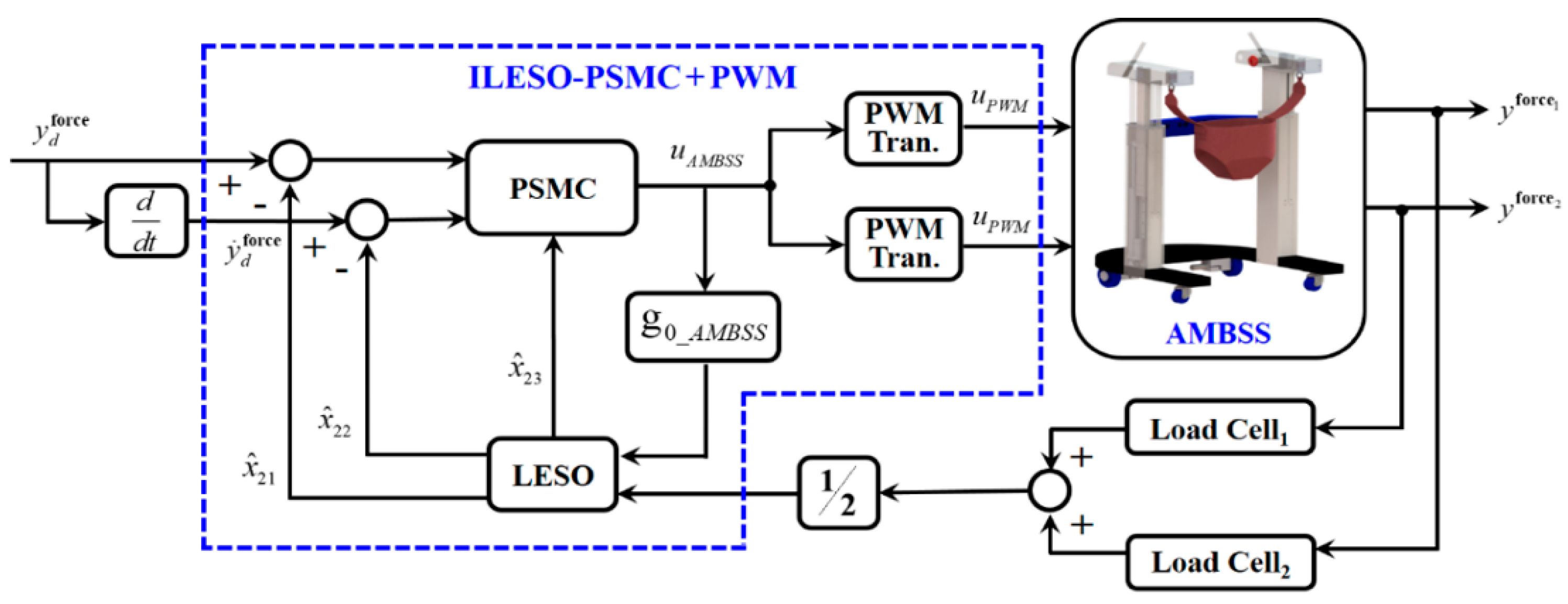
where is the target unloading force, is the runtime of AMBSS, denotes the force tracking trajectory and is the running time. The experiments involved assessments of the AMBSS using the ILESO-PSMC in the following experiments. The parameters used for the ILESO-PSMC in the experiments are presented in Table 1. Figure 5 shows the control block of the AMBSS containing the ILESO-PSMC, where is the target load trajectory described by the fifth-degree polynomial function expressed in Equation (32). is the support force of the right linear actuator, and is the support force of the left linear actuator. The ILESO-PSMC outputs the PWM signal to “PWM Transform”, denoted as for the right and left linear actuators. Then, the PWM control signal was calculated adopting the PWM transformation function to convert the LESO-PSMC output into a PWM signal. The PWM transformation function is expressed as follows:
where is the period of the carrier wave, is the controller output of the ILESO-PSMC, and is the PWM duty cycle of the linear actuators. The control voltage of the linear actuator is If the linear actuator moves upward; if the linear actuator moves downward; and if the linear actuator ceases. The ILESO-PSMC provides control signals to the linear actuator at a sampling rate of 100 Hz. Therefore, 0.01 s was used as the carrier wave period in this unloading force control. Two linear actuators excited by the PWM signal controlled the output support forces of ABWSS. In practice, the ILESO-PSMC provides unanimous PWM signals for both side linear actuators; thus, the AMBSS could run smoothly. The input of the LESO was the average of the measured outputs of the two load cells.
Two healthy subjects with no history of disability—a woman with a weight of 47.5 kg and a height of 1.5 m and a healthy man with a weight of 88 kg and a height of 1.68 m—participated in the experimental evaluation. We performed experiments with different bodyweight unloading forces for the AMBSS, mainly 15%, 20%, 25%, and 40% weight support. Two bodyweight support control strategies—static and dynamic unloading force control—were adopted in the first experimental project to evaluate the availability of the AMBSS. The static unloading force control was tested when the AMBSS was stationary. The dynamic unloading force control was tested while the AMBSS followed the participant walking without the LES. For the dynamic unloading force test, we considered the vertical motion of the trunk while the subject was walking as an external disturbance. In the first experiment project, the static unloading force target of female subject was set as 20% (93.1 N) and 40% (186.2 N) of body weight (47.5 kg × 9.8 m/s = 465.5 N); the static unloading force target of male subject was set as 15% (129.4 N) and 25% (215.6 N) of body weight (88 kg × 9.8 m/s = 862.4 N). Figure 6 and Figure 7 display the experimental results of the static unloading force control for male and female subjects, respectively. Figure 8 and Figure 9 show the experimental results of dynamic unloading force control for male and female subjects at the same unloading force settings as static unloading force control. To guarantee the subject’s safety, the ILESO-PSMC with PWM applied smooth and gentle control of the support force supplied by the AMBSS. Figure 6a and Figure 7a show that different subjects could achieve static unloading force to varying percentages of their bodyweight in approximately 30 s. Figure 8a and Figure 9a indicate that different subjects could also achieve dynamic unloading force to varying percentages of bodyweight in approximately 30 s. For the ILESO-PSMC strategy, the maximum deviation for dynamic unloading force while walking is no more than 9 N. Precise maintenance of the set dynamic unloading force was impossible for the AMBSS due to the vertical displacements of the torso during walking. The oscillations around the goal unloading force value shown in Figure 8 and Figure 9 are caused by the torso’s movement, which we interpret as disturbances. The results show that AMBSS can provide compensation force by the ILESO-PSMC to achieve accurate dynamic unloading force control.
5.3. Lower Limb Exoskeleton Gait Trajectory Tracking Control
During the initial rehabilitation phase, the LES assists the subject in walking in a passive mode according to a given gait trajectory. Model-based control depends on the accuracy of the system models, while model-free methods have limitations in dealing with disturbance issues, as is the case with standard PID strategies. Under the premise of safety, the main target of the LES is to track a given gait trajectory with high precision under external disturbances. The ILESO-PSMC can estimate the unknown disturbances of the LES and eliminate the effect on the designed controller to achieve both safety and good trajectory tracking performance. It is critical to knowing the gait cycle of a healthy person walking over-ground for LES-assisted gait continuous passive motion (CPM) training therapy. A complete gait cycle in a healthy person is defined as the progression of movement of one leg returning to a specific angle. The normal person’s gait trajectory required for this study was derived from the Clinical Gait Analysis [17]. With a gait period of two seconds, the continuous variation in the rotation angle over time was determined by the Fourier series fitting method, providing the following two continuous rotation angle functions for the hip and knee joints [32]:
and
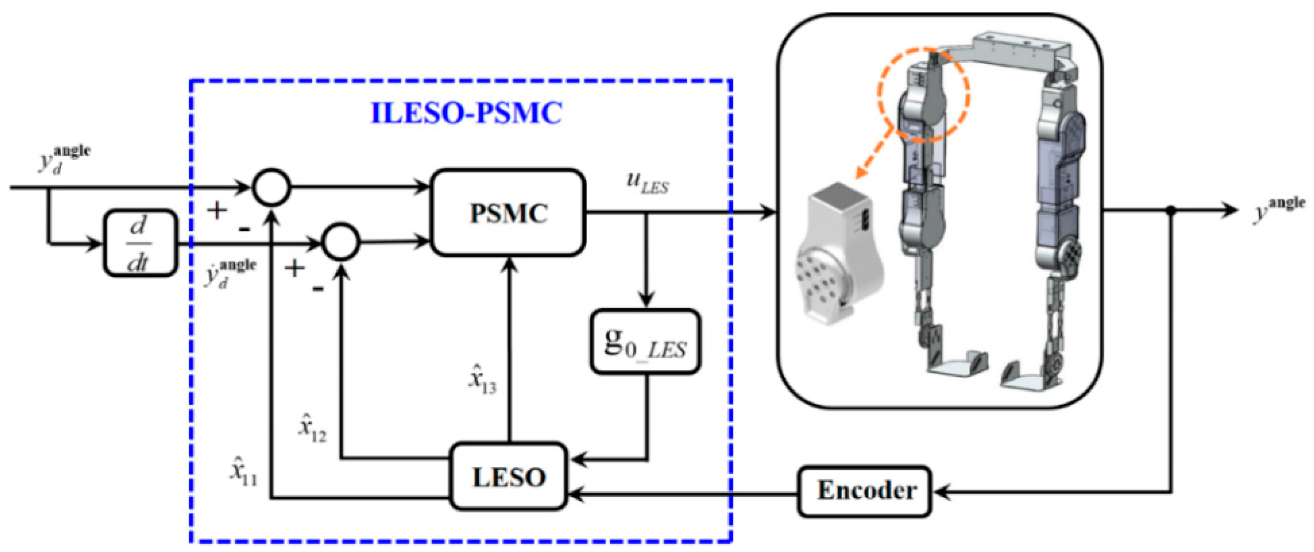
Figure 10a,b show the regular gait-training cycle for the experiments, described as angle trajectories, for the knee and hip, respectively, during the standard two-second gait period. The period of gait training is modifiable. For example, the gait period can be adjusted to two times the standard reference gait-training period for 4 seconds of gait training. We suppose the LES to be a decoupled system; therefore, the interaction of the knee and hip joints will be considered as external disturbances in the controller design [32]. Therefore, four direct-current servo motor modules drive the LES for over-ground gait CPM training. Each direct-current servo motor module includes a direct-current servo motor and its driver. The LES uses four ILESO-PSMCs, tracking a gait trajectory captured from a healthy human by regulating four direct-current servo motors. Figure 11 shows the single joint control block of the LES. In the second experiment, the required gait tracking trajectories for each joint of the LES were derived by extending the period of fitting expression to 5 seconds. The reference angle trajectories for the knee and hip joints were calculated using Equations (34) and (35). The ILESO-PSMC is shown in Equation (28) as A trial-and-error method was used to select control parameters for accuracy and compliance. The parameters of ILESO-PSMCs for the direct-current servo motors were chosen as shown in Table 2.
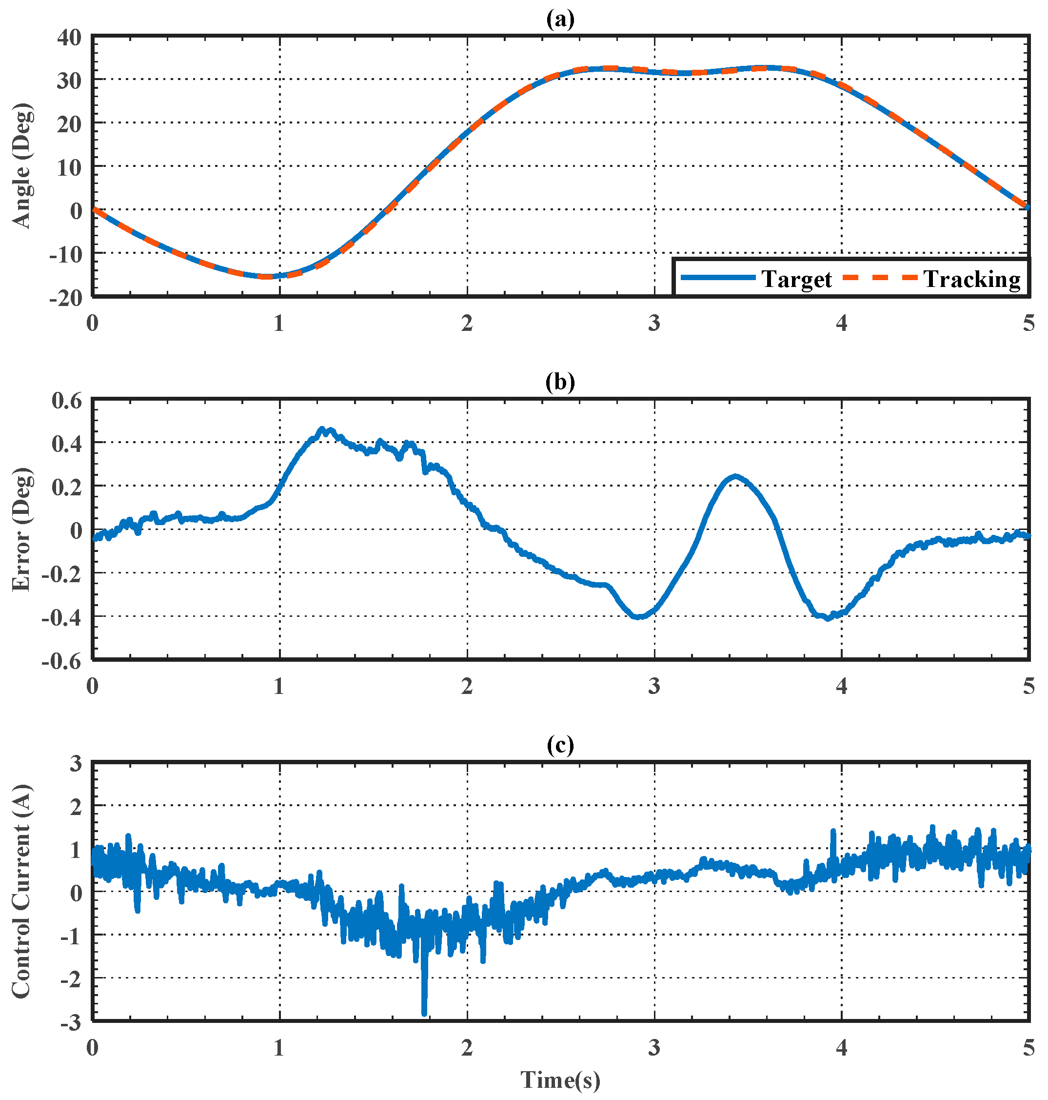
The lower limb joint trajectory tracking and safety performance tests were performed for the LES to evaluate the proposed control scheme. The LES experiments were executed with a healthy wearer. All experiments were performed under the aegis of safe premises. The healthy male wearer in this study had a height of 1.68 m and a weight of 88 kg. The LES drives the human lower limb to move. Figure 12 and Figure 13 show the tracking performance of the joint trajectory tracking experiment using ILESO-PSMC, where Figure 12a and Figure 13a illustrate the angle tracking results for the knee joint and hip joint, respectively. Figure 12b and Figure 13b present the angle tracking error of the knee joint and hip joint, respectively, where the error of the knee joint is within the interval of (−0.4, 0.4) degrees, while that of the hip joint is within the interval of (−0.4, 0.5). Figure 12c and Figure 13c show the current control signal of the ILESO-PSMC for the right knee and hip joint, respectively.
5.4. Using the MRR for Over-Ground Gait Training
The MRR can guide and help subjects to perform over-ground walking. However, when walking, the subject’s posture and center of the mass are variable while wearing the LES; therefore, it is challenging to maintain a stable unloading force while wearing the LES. The designed MRR provides subjects with stable and robust bodyweight unloading force during ground gait training. The third experiment was performed to decide the availability of the MRR adopting to an ILESO-PSMC. The AMBSS was controlled to lead a subject to walk forward at a set speed. In the experimental evaluation, a healthy male subject with a height of 1.7 m and a weight of 70 kg without a history of disability was used. The bodyweight unloading force for the AMBSS was set to 20% weight reduction of the user’s body weight. The complete gait cycle for the LES was set to 5 s. The control parameters of the gait training experiment are listed in Table 1 and Table 2. During the first 30 s, AMBSS progressively increased the bodyweight unloading force to 20% of the subject’s body weight. After reaching the set bodyweight unloading force, the AMBSS cooperated with the LES and moved forward at a gait speed of 5 s for repeated over-ground gait training. The LES enabled over-ground gait trajectory tracking control, and the AMBSS started to execute bodyweight support control. The unloading force target was 20% (137.2 N) of the subject’s body weight. Figure 14a shows that the AMBSS slowly and comfortably reached an unloading force of 20% of the subject’s body weight within 30 s. The bodyweight unloading force tracking error in the first 30 s was within the interval of (−12, 18) N. The movement of MRR made it difficult to control the bodyweight unloading force; therefore, the bodyweight unloading force tracking error increased to an interval of (−22, 30) N at 30–85 s. Figure 14c presents the PWM control signals of the AMBSS, which are regarded as duty cycles. The maximum signal values appeared in the over-ground gait training stage, i.e., during the tautening and relaxing of the harness, causing the maximum tracking error in the walking stage (Figure 14b). Clearly, the ILESO-PSMC was effectively able to bound the tracking errors. Figure 15a and Figure 16a display the trajectory-tracking performance of the right hip and knee joints during the CPM gait trajectory tracking process, respectively. Figure 15b and Figure 16b illustrate the angle trajectory tracking error of the knee and hip joints during CPM gait trajectory tracking, respectively. During over-ground CPM gait trajectory tracking, the angle tracking errors of the knee and hip were about ±0.6° and ±1°, respectively. Figure 15c and Figure 16c indicate the control current of the ILESO-PSMCs for the knee and hip. The performance of bodyweight support control and over-ground gait trajectory tracking control deteriorated due to coupling effects.
5.5. Discontinuity Recovery Safety Performance Test
This experiment was conducted to show the motion recovery from significant angular errors. We used a discontinuous position function to examine the performance on resuming motion and compare it with the PID stiff position control. The discontinuous position function is shown as:
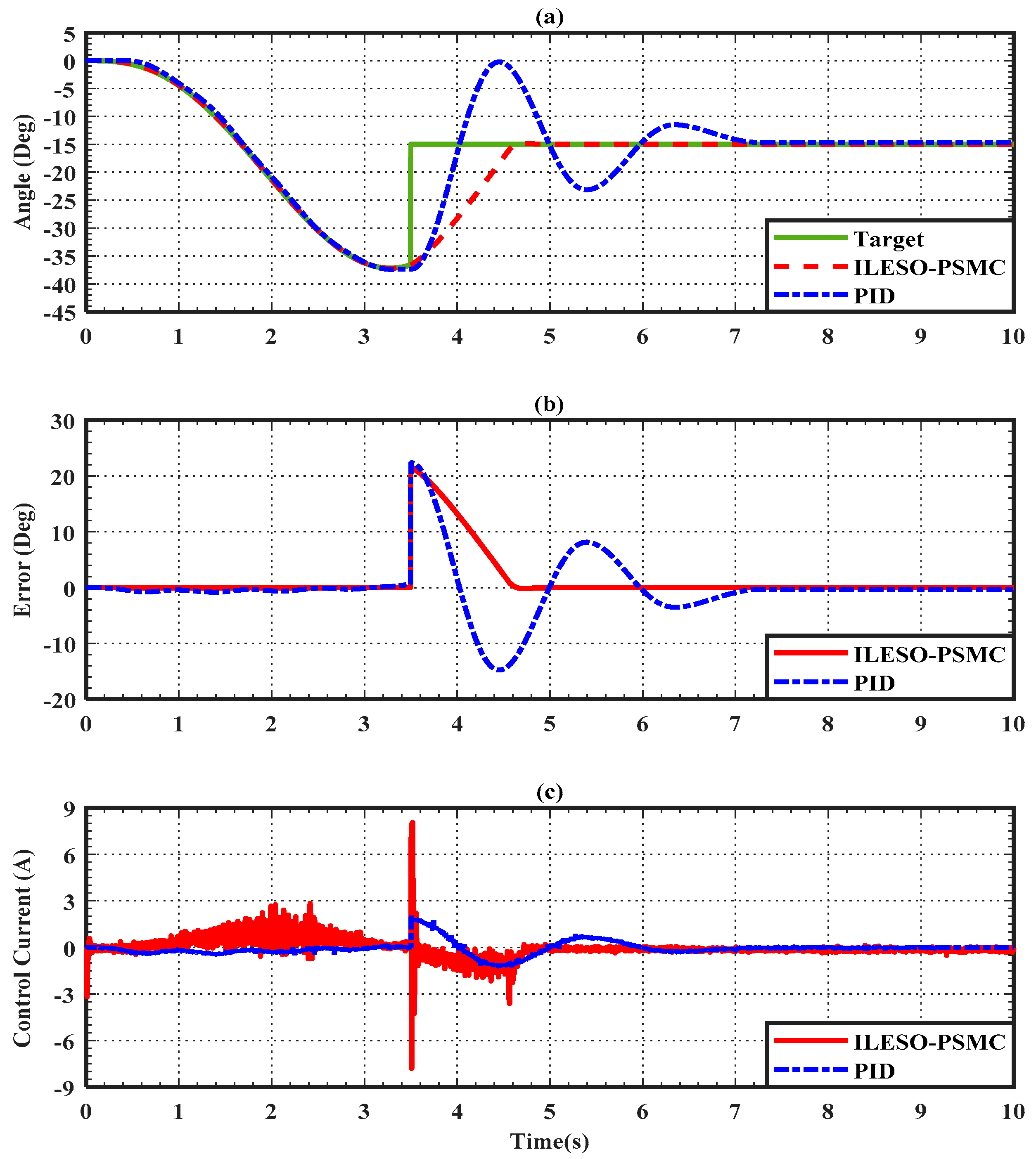
The parameters for PID stiff position control were chosen to be . The design of the LES was identical to those used in the first three experiments, as listed in Table 2. Figure 17 shows the tracking results of both control strategies. The results show a quite similar performance between the ILESO-PSMC tracking and the PID stiff position controller when the reference trajectory was continuous and smooth. However, the PID controller shows oscillations when positional discontinuity appears, while ILESO-PSMC still performed smooth, slow, and safe position tracking toward the desired value. Overshoot occurred during the quick recovery process when using the PID, while overdamped recovery occurred when using the ILESO-PSMC. Thus, the ILESO-PSMC can guarantee the system’s safety by canceling the overshoot during the position tracking. Figure 17 shows no chattering in the tracking trajectory when using the ILESO-PSMC. Hence, the ILESO-PSMC presents the advantages of safety and accuracy, which are inherited from the ideal SMC; conversely, the PID stiff position control cannot provide these advantages because of the overshoot.
6. Conclusions
This paper proposes an MRR integrating LES and AMBSS for over-ground gait CPM training under dynamic unloading force. The MRR provides multiple training functions for individuals with weakness in the lower extremities who need gait training or mobility aid. Furthermore, the ILESO-PSMC approach was developed in this study to control the unloading force of AMBSS and gait trajectory tracking control of LES. This approach enables the AMBSS and LES to perform smooth, slow, and damped recovery from abnormal states and to allow minor tracking errors in regular situations with no chattering, thus producing an accurate unloading force and current output. The safety performance of ILESO-PSMC was evaluated while tracking a discontinuous signal input. In addition, the stability of the developed ILESO-PSMC was proved through Lyapunov analysis, and the real-time experiments for the MRR were used to verify the effectiveness. The experimental results show that ILESO-PSMCs can reduce the angle tracking errors of the hip and knee joints to around ±0.6° and ±1°, respectively, during over-ground gait trajectory tracking. The ILESO-PSMC controls the unloading force for the AMBSS to compensate for the lower limb bearing capacity. After compensation, the ILESO-PSMC could reduce the dynamic bodyweight unloading force error for the AMBSS to about 20%. Thus, the ILESO-PSMC has the potential to achieve safety and tracking performance in the preliminary rehabilitation phase compared to the conventional stiff position control methods, and can be accomplished and applied to other rehabilitation control systems.
7. Patents
The mobile rehabilitation robot developed has obtained a Taiwanese invention patent and a US invention patent. These are (1) MULTIFUNCTION LOWER LIMB GAIT REHABILITATION AND WALKING ASSIST MACHINE, Taiwanese pa-tent number I55555 and (2) MULTI-FUNCTION LOWER LIMB AMBULATION REHABILITATION AND WALKING ASSIST DEVICE, US patent number US 9,789,023 B1.
Author Contributions
Conceptualization, L.-W.L. and I.-H.L.; methodology, L.-W.L., T.-J.S. and S.-J.C.; software, Y.-B.H., L.-Y.L. and I.-H.L.; validation, L.-Y.L., I.-H.L., S.-J.C. and T.-J.S.; formal analysis, L.-W.L., S.-J.C. and I.-H.L.; investigation, L.-W.L. and I.-H.L.; resources, L.-W.L.; data curation, L.-W.L. and Y.-B.H.; writing—original draft preparation, L.-W.L. and I.-H.L.; writing—review and editing, L.-W.L. and I.-H.L.; supervision, L.-W.L. and T.-J.S.; project administration, L.-W.L. and S.-J.C.; funding acquisition, L.-W.L. All authors have read and agreed to the published version of the manuscript.
Funding
This research has financial support from Ministry of Science and Technology, R. O. C. Grant: MOST 110-2221-E-005-083-.
Institutional Review Board Statement
The study was conducted in accordance with the Declaration of Helsinki, and approved by the Institutional Review Board (or Ethics Committee) of Fu Jen Catholic University Institutional Review Board (protocol code C103134 and date of approval 2015/06/22).” for studies involving humans.
Informed Consent Statement
Informed consent was obtained from all subjects involved in the study.
Acknowledgments
This research is sponsored by the Ministry of Science and Technology, Taiwan, under Grants No. MOST 110-2221-E-005-083- and MOST 110-2221-E-032-036-.
Conflicts of Interest
The authors declare no conflict of interest.
References
- Alias, N.A.; Huq, M.S.; Ibrahim, B.S.K.K.; Omar, R. The Efficacy of State of the Art Overground Gait Rehabilitation Robotics: A Bird’s Eye View. Procedia Comput. Sci. 2017, 105, 365–370. [Google Scholar] [CrossRef]
- Srivastava, S.P.; Kao, C.S.; Kim, H.; Stegall, P.; Zanotto, D.; Higginson, J.S.; Agrawal, S.K.; Scholz, J.P. Assist-as-needed robot-aided gait training improves walking function in individuals following stroke. IEEE Trans. Neural Syst. Rehabil. Eng. 2015, 23, 956–963. [Google Scholar] [CrossRef]
- Chen, G.; Zhou, Z.; Vanderborght, B.; Wang, N.; Wang, Q. Proxy-based sliding mode control of a robotic ankle-foot system for post-stroke rehabilitation. Adv. Robot. 2016, 30, 992–1003. [Google Scholar] [CrossRef]
- Kang, C.J.; Chum, M.H.; Lee, J.; Lee, J.Y. Effects of robot (SUBAR)-assisted gait training in patients with chronic stroke. Medicine 2021, 100, e27974. [Google Scholar] [CrossRef]
- Steven, L.; Pattawong, P.; Ash, R.; James, M.T.; Sri, K.; Mircea, T. A Soft Exosuit for Flexible Upper-Extremity Rehabilitation. IEEE Trans. Neural Syst. Rehabil. Eng. 2018, 26, 1604–1617. [Google Scholar]
- Alan, F.P.V.; Jesse, Y.R.M.; Gerardo, O.T.; Felipe, J.S.V.; Alan, C.R.; Jorge, A.B.M.; Julio, C.R.C. Soft Exoskeletons: Development, Requirements, and Challenges of the Last Decade. Actuators 2021, 10, 166. [Google Scholar]
- Nedergård, H.; Arumugam, A.; Sandlund, M.; Bråndal, A.; Häger, C.K. Effect of robotic-assisted gait training on objective biomechanical measures of gait in persons post-stroke: A systematic review and meta-analysis. J. Neuroeng. Rehabil. 2021, 18, 64. [Google Scholar] [CrossRef]
- Pamungkas, D.S.; Caesarendra, W.; Soebakti, H.; Analia, R.; Susanto, S. Overview: Types of Lower Limb Exoskeletons. Electronics 2019, 8, 1283. [Google Scholar] [CrossRef]
- Banala, S.K.; Agrawal, S.K.; Kim, S.H.; Scholz, J.P. Novel Gait Adaptation and Neuromotor Training Results Using an Active Leg Exoskeleton. IEEE/ASME Trans. Mechatron. 2010, 15, 216–225. [Google Scholar] [CrossRef]
- Nam, K.Y.; Kim, H.J.; Kwon, B.S.; Park, J.W.; Lee, H.J.; Yoo, A. Robot-assisted gait training (Lokomat) improves walking function and activity in people with spinal cord injury: A systematic review. J. Neuroeng. Rehabil. 2017, 14, 24. [Google Scholar] [CrossRef]
- Hobbs, B.; Artemiadis, P. A Review of Robot-Assisted Lower-Limb Stroke Therapy: Unexplored Paths and Future Directions in Gait Rehabilitation. Front. Neurorobot. 2020, 14, 19. [Google Scholar] [CrossRef]
- Kim, S.K.; Park, D.; Yoo, B.; Shim, D.; Choi, J.O.; Choi, T.Y.; Park, E.S. Overground Robot-Assisted Gait Training for Pediatric Cerebral Palsy. Sensors 2021, 21, 2087. [Google Scholar] [CrossRef]
- Eloy, U.; Guillermo, A.P.; Ramón, C.; Rodrigo, G.C.; Rafael, R.; José, L.P. HYBRID: Ambulatory Robotic Gait Trainer with Movement Induction and Partial Weight Support. Sensors 2019, 19, 4773. [Google Scholar]
- Elena, M.; Simona, C.; Andrea, P.; Luca, B.; Ugo, F.; Zach, M.; Raffaello, M.L.; Lorenza, P.; Nicola, V. Gait training using a robotic hip exoskeleton improves metabolic gait efciency in the elderly. Sci. Rep. 2019, 9, 7157. [Google Scholar]
- Kim, H.Y.; Shin, J.H.; Yang, S.P.; Shin, M.A.; Lee, S.H. Robot-assisted gait training for balance and lower extremity function in patients with infratentorial stroke: A single-blinded randomized controlled trial. J. Neuroeng. Rehabil. 2019, 16, 99. [Google Scholar] [CrossRef]
- Knaepen, K.; Beyl, P.; Duerinck, S.; Hagman, F.; Lefeber, D.; Meeusen, R. Human-robot interaction: Kinematics and muscle activity inside a powered compliant knee exoskeleton. IEEE Trans. Neural Syst. Rehabil. Eng. 2014, 22, 1128–1137. [Google Scholar] [CrossRef]
- Lee, L.W.; Li, I.H.; Liang, T.W. A Proof of Concept Study for the Design, Manufacturing, and Control of a Mobile Overground Gait-Training System. Int. J. Fuzzy Syst. 2021, 23, 2396–2416. [Google Scholar] [CrossRef]
- Liu, T.P.; Low, K.H.; Qu, X.; Lim, H.B.; Hoon, K.H. Hardware development and locomotion control strategy for an over-ground gait trainer: NaTUre-Gaits. IEEE J. Transl. Eng. Health Med. 2014, 2, 1–9. [Google Scholar] [CrossRef]
- Marks, D.; Schweinfurther, R.; Dewor, A.; Huster, T.; Paredes, L.P.; Zutter, D.; Möller, J.C. The Andago for overground gait training in patients with gait disorders after stroke—GaitTrainer ults from a usability study. Physiother. Res. Rep. 2019, 2, 1–8. [Google Scholar] [CrossRef]
- Seo, K.H.; Lee, J.J. The development of two mobile gait rehabilitation systems. IEEE Trans. Neural Syst. Rehabil. Eng. 2009, 17, 156–166. [Google Scholar] [CrossRef]
- Stauffer, Y.; Allemand, Y.; Bouri, M.; Fournier, J.; Clavel, R.; Metrailler, P.; Brodard, R.; Reynard, F. The walktrainer-a new generation of walking reeducation device combining orthoses and muscle stimulation. IEEE Trans. Neural Syst. Rehabil. Eng. 2009, 17, 38–45. [Google Scholar] [CrossRef]
- Benamor, A.; Messaoud, H. Robust adaptive sliding mode control for uncertain systems with unknown time-varying delay input. ISA Trans. 2018, 79, 1–12. [Google Scholar] [CrossRef]
- Pan, Y.; Yang, C.; Pan, L.; Yu, H. Integral sliding mode control: Performance, modification, and improvement. IEEE Trans. Ind. Inform. 2018, 14, 3087–3096. [Google Scholar] [CrossRef]
- Ryo, K.; Satoshi, Y.; Hideo, F.; Motoji, Y. Proxy-based sliding mode control: A safer extension of PID position control. IEEE Trans. Robot. 2010, 26, 670–683. [Google Scholar]
- Gu, G.Y.; Zhu, L.M.; Su, C.Y.; Ding, H.; Fatikow, S. Proxy-based sliding-mode tracking control of piezoelectric-actuated nanopositioning stages. IEEE/ASME Trans. Mechatron. 2015, 20, 1956–1965. [Google Scholar] [CrossRef]
- Huo, W.; Paniagua, V.A.; Ding, G.; Amirat, Y.; Mohammed, S. Adaptive proxy-based controller of an active ankle foot orthosis to assist lower limb movements of paretic patients. Robotica 2019, 37, 2147–2164. [Google Scholar] [CrossRef]
- Kashiri, N.; Lee, J.; Tsagarakis, N.G.; Damme, M.V.; Vanderborght, B.; Caldwell, D.G. Proxy-based position control of manipulators with passive compliant actuators: Stability analysis and experiments. Robot. Auton. Syst. 2016, 75, 398–408. [Google Scholar] [CrossRef]
- Lee, L.W.; Lu, C.Y.; Li, I.H.; Lee, C.W.; Su, T.J. Design and control of a 6-DOF robotic manipulator driven by pneumatic muscles and motor. Sens. Mater. 2021, 33, 3081–3100. [Google Scholar] [CrossRef]
- Prieto, P.J.; Rubio, E.; Hernandez, L.; Orlando, U. Proxy-based sliding mode control on platform of 3 degree of freedom (3-DOF). Adv. Robot. 2013, 27, 773–784. [Google Scholar] [CrossRef]
- Ryo, K. Sliding motion accuracy of proxy-based sliding mode control subjected to measurement noise and disturbance. Eur. J. Control 2021, 58, 114–122. [Google Scholar]
- Zhao, W.; Song, A.; Cao, Y. An Extended Proxy-Based Sliding Mode Control of Pneumatic Muscle Actuators. Appl. Sci. 2019, 9, 1571. [Google Scholar] [CrossRef]
- Long, Y.; Du, Z.; Cong, L.; Wang, W.; Zhang, Z.; Dong, W. Active disturbance rejection control based human gait tracking for lower extremity rehabilitation exoskeleton. ISA Trans. 2017, 67, 389–397. [Google Scholar] [CrossRef]
- Hwang, B.; Jeon, D. A method to accurately estimate the muscular torques of human wearing exoskeletons by torque sensors. Sensors 2015, 15, 8337–8357. [Google Scholar] [CrossRef]
- Gurav, B.; Economou, J.; Saddington, A.; Knowles, K. Multi-Mode Electric Actuator Dynamic Modelling for Missile Fin Control. Aerospace 2017, 4, 30. [Google Scholar] [CrossRef]
- Hipolito, A.S.; Wen, Y.; Sergio, S.; Ricardo, L. Design and control of hybrid actuation lower limb exoskeleton. Adv. Mech. Eng. 2015, 7, 1687814015590988. [Google Scholar]
- Jiang, W.; Zhu, G.; Zheng, Y. Iterative Learning Control for AGV Drive Motor Based on Linear Extended State Observer. Machines 2021, 9, 324. [Google Scholar] [CrossRef]
- Gao, Z. Scaling and bandwith-parameterization based controller tuning. In Proceedings of the American Control Conference 2003, Denver, CO, USA, 4–6 June 2003; pp. 4989–4996. [Google Scholar]
- Zhao, L.; Zheng, C.; Wang, Y.; Liu, B. A Finite-Time Control for a Pneumatic Cylinder Servo System Based on a Super-Twisting Extended State Observer. IEEE Trans. Syst. Man Cybern. Syst. 2021, 51, 1164–1173. [Google Scholar] [CrossRef]
- Madonski, R.; Shao, S.; Zhang, H.; Gao, Z.; Yang, J.; Li, S. General error-based active disturbance rejection control for swift industrial implementations. Control Eng. Pract. 2019, 84, 218–229. [Google Scholar] [CrossRef]
- Li, S.H.; Yang, J.; Chen, W.H.; Chen, X.S. Generalized Extended State Observer Based Control for Systems with Mismatched Uncertainties. IEEE Trans. Ind. Electron. 2012, 59, 4792–4802. [Google Scholar] [CrossRef]
- Xu, B.; Ji, S.; Zhang, C.; Chen, C.; Ni, H.; Wu, X. Linear-extended-state-observer-based prescribed performance control for trajectory tracking of a robotic manipulator. Ind. Robot. 2021, 48, 544–555. [Google Scholar] [CrossRef]
- Wu, Q.; Yu, L.; Wang, Y.W.; Zhang, W.A. LESO-based position synchronization control for networked multi-axis servo systems with time-varying delay. IEEE CAA J. Autom. Sin. 2020, 7, 1116–1123. [Google Scholar] [CrossRef]
- Ma, Y.; Yang, L.; Zhou, X.; Yang, X. Second-order linear active disturbance rejection control and stability analysis of energy storage grid-connected inverter. IEEE Access 2020, 8, 160738–160748. [Google Scholar] [CrossRef]
Figure 1.
The overall design concept and prototype photos of the MRR.

Figure 2.
Modeling of the active mass-offload AMBSS.
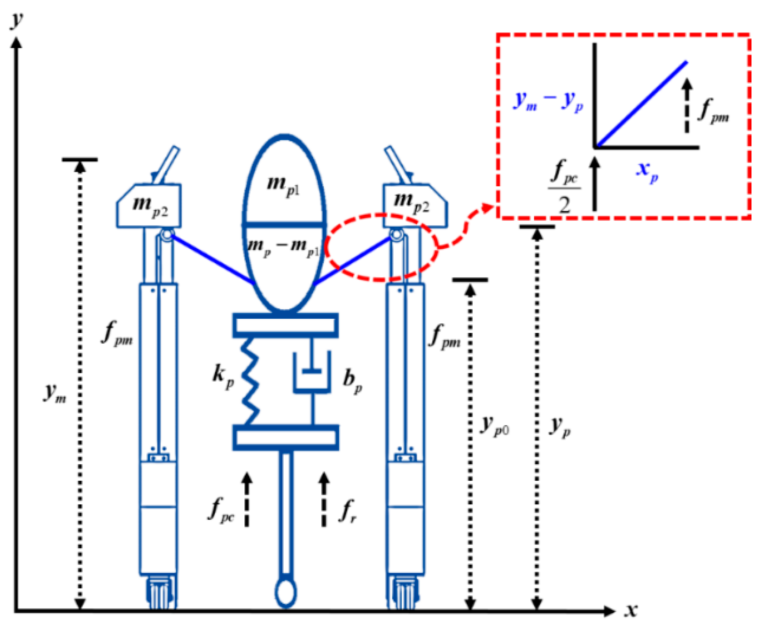
Figure 3.
The principle of the physical model of ILESO-PSMC.
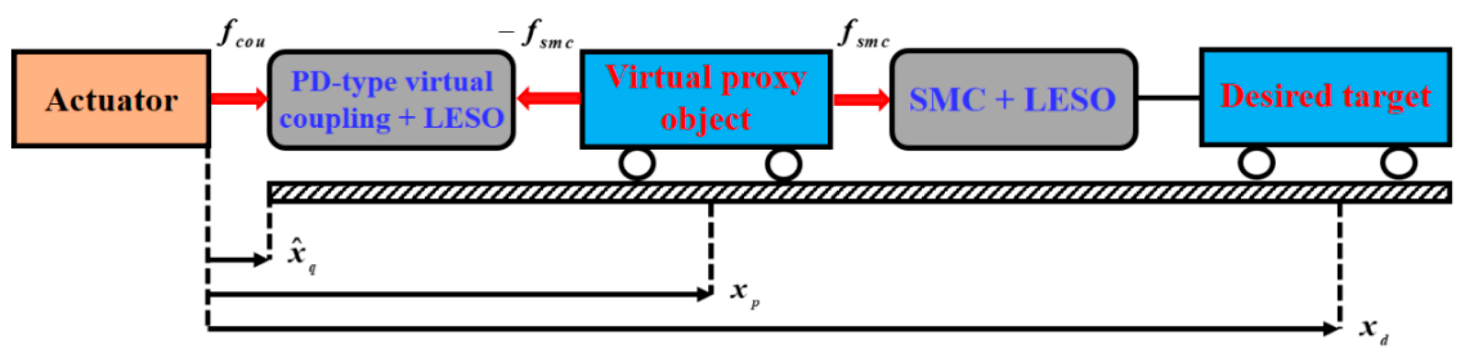
Figure 4.
MRR’s control system architecture diagram.
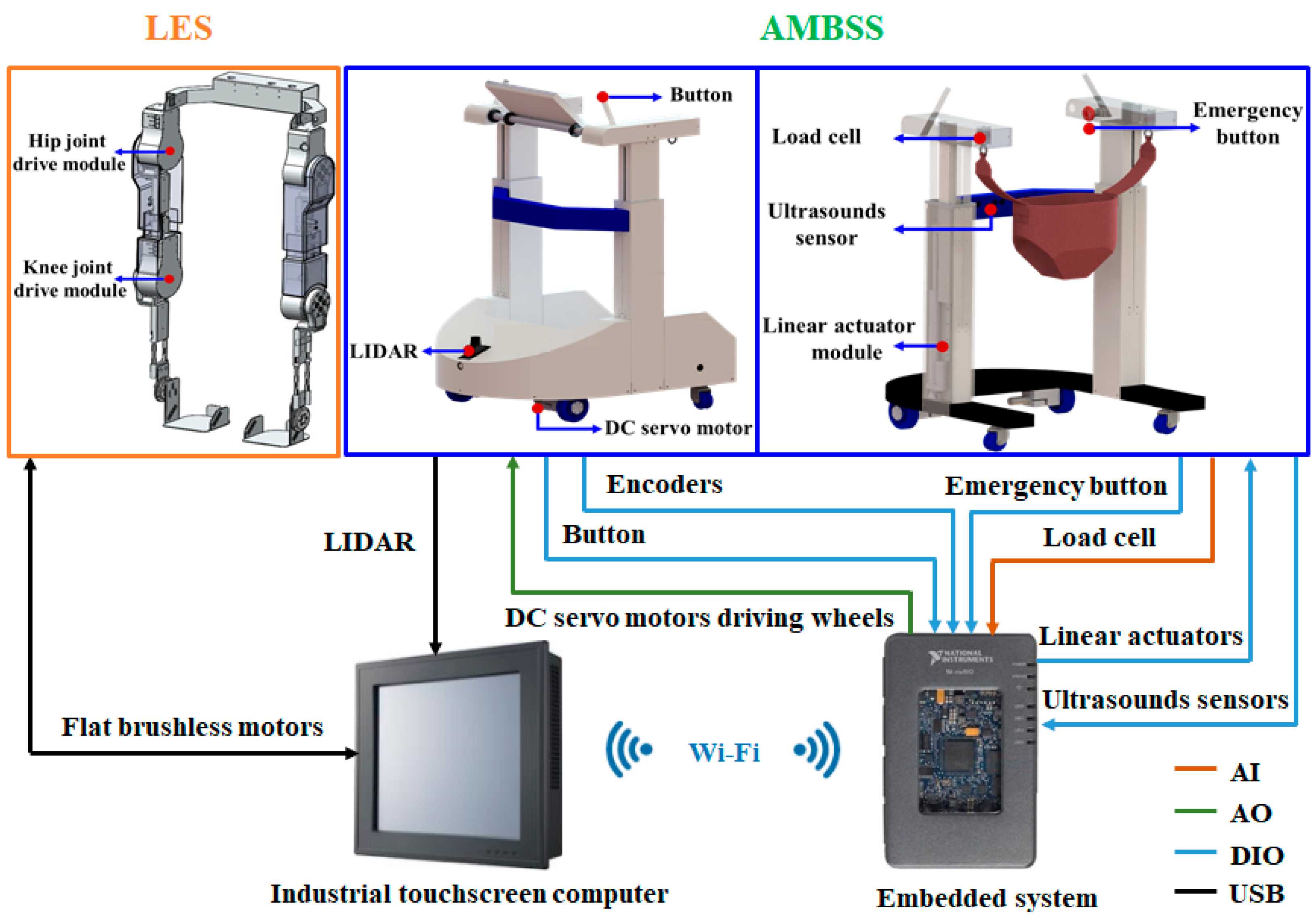
Figure 5.
Control block of the AMBSS.

Figure 6.
Static bodyweight unloading force control of ILESO−PSMC, 15% (129.4 N) and 25% (215.6 N) of female subject body weight (862.4 N). (a) Unloading force tracking response; (b) unloading force tracking error; (c) duty cycle of PWM.
Figure 6.
Static bodyweight unloading force control of ILESO−PSMC, 15% (129.4 N) and 25% (215.6 N) of female subject body weight (862.4 N). (a) Unloading force tracking response; (b) unloading force tracking error; (c) duty cycle of PWM.
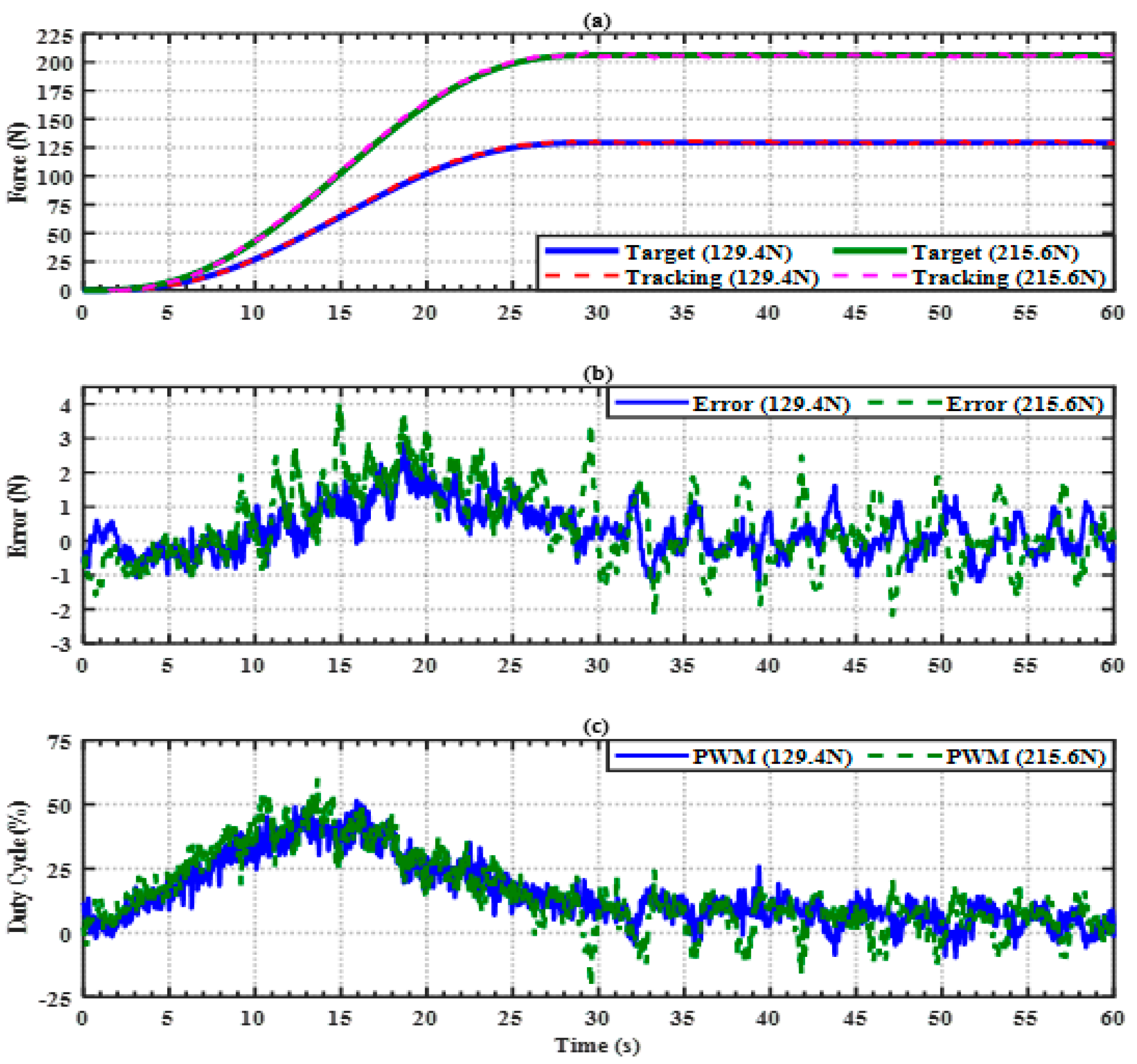
Figure 7.
Static bodyweight unloading force control of ILESO−PSMC, 20% (93.1 N) and 40% (182.6 N) of female subject body weight (465.5 N). (a) Unloading force tracking response; (b) unloading force tracking error; (c) duty cycle of PWM.
Figure 7.
Static bodyweight unloading force control of ILESO−PSMC, 20% (93.1 N) and 40% (182.6 N) of female subject body weight (465.5 N). (a) Unloading force tracking response; (b) unloading force tracking error; (c) duty cycle of PWM.
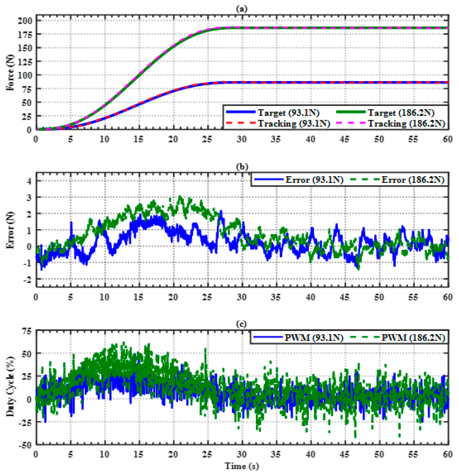
Figure 8.
Dynamic bodyweight unloading force control of ILESO−PSMC, 15% (129.4 N) and 25% (215.6 N) of male subject body weight (862.4 N). (a) Unloading force tracking response; (b) unloading force tracking error; (c) duty cycle of PWM.
Figure 8.
Dynamic bodyweight unloading force control of ILESO−PSMC, 15% (129.4 N) and 25% (215.6 N) of male subject body weight (862.4 N). (a) Unloading force tracking response; (b) unloading force tracking error; (c) duty cycle of PWM.
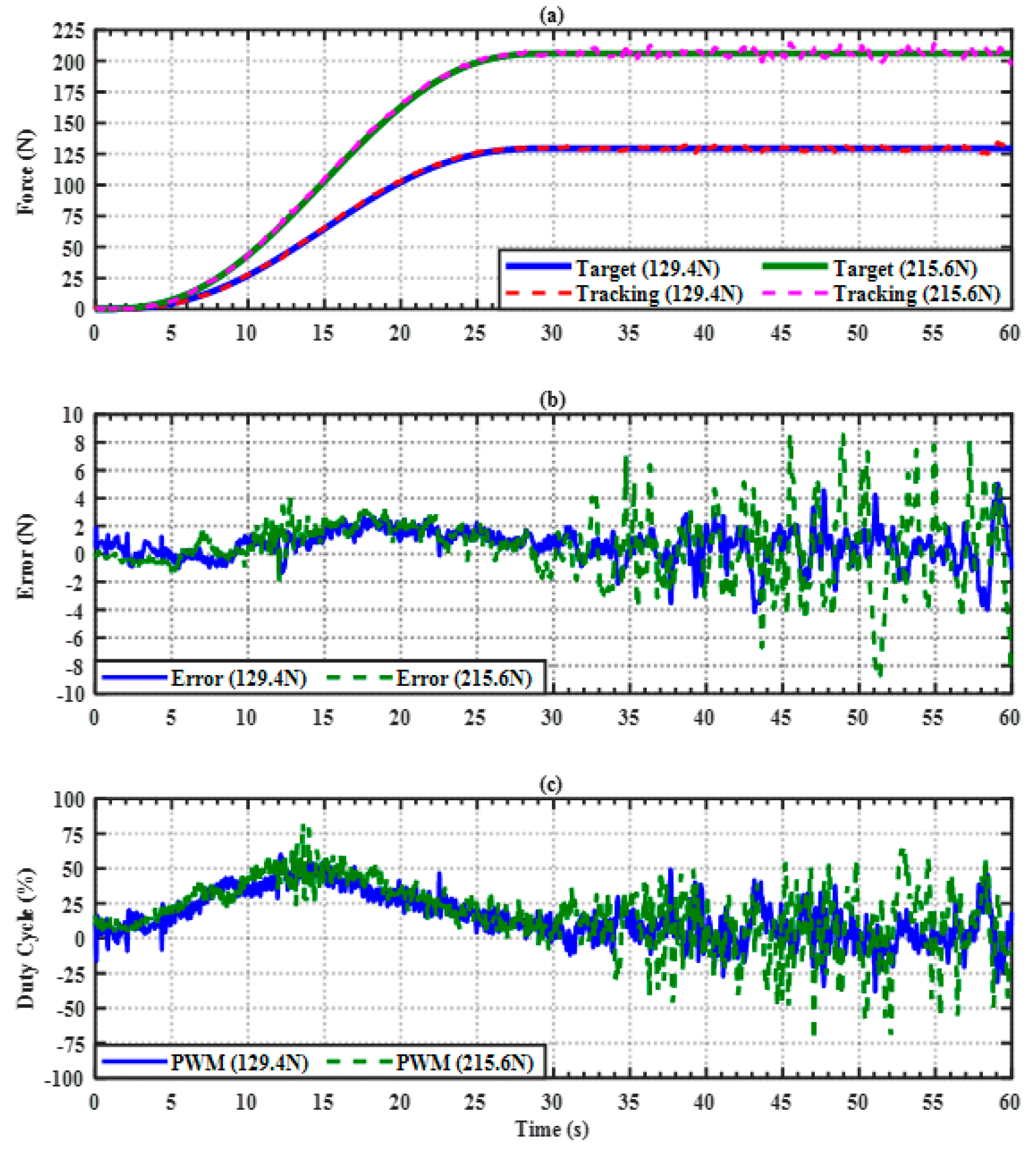
Figure 9.
Dynamic bodyweight unloading force control of ILESO−PSMC, 20% (93.1 N) and 40% (186.2 N) of female subject body weight (845.5 N). (a) Unloading force tracking response; (b) unloading force tracking error; (c) duty cycle of PWM.
Figure 9.
Dynamic bodyweight unloading force control of ILESO−PSMC, 20% (93.1 N) and 40% (186.2 N) of female subject body weight (845.5 N). (a) Unloading force tracking response; (b) unloading force tracking error; (c) duty cycle of PWM.
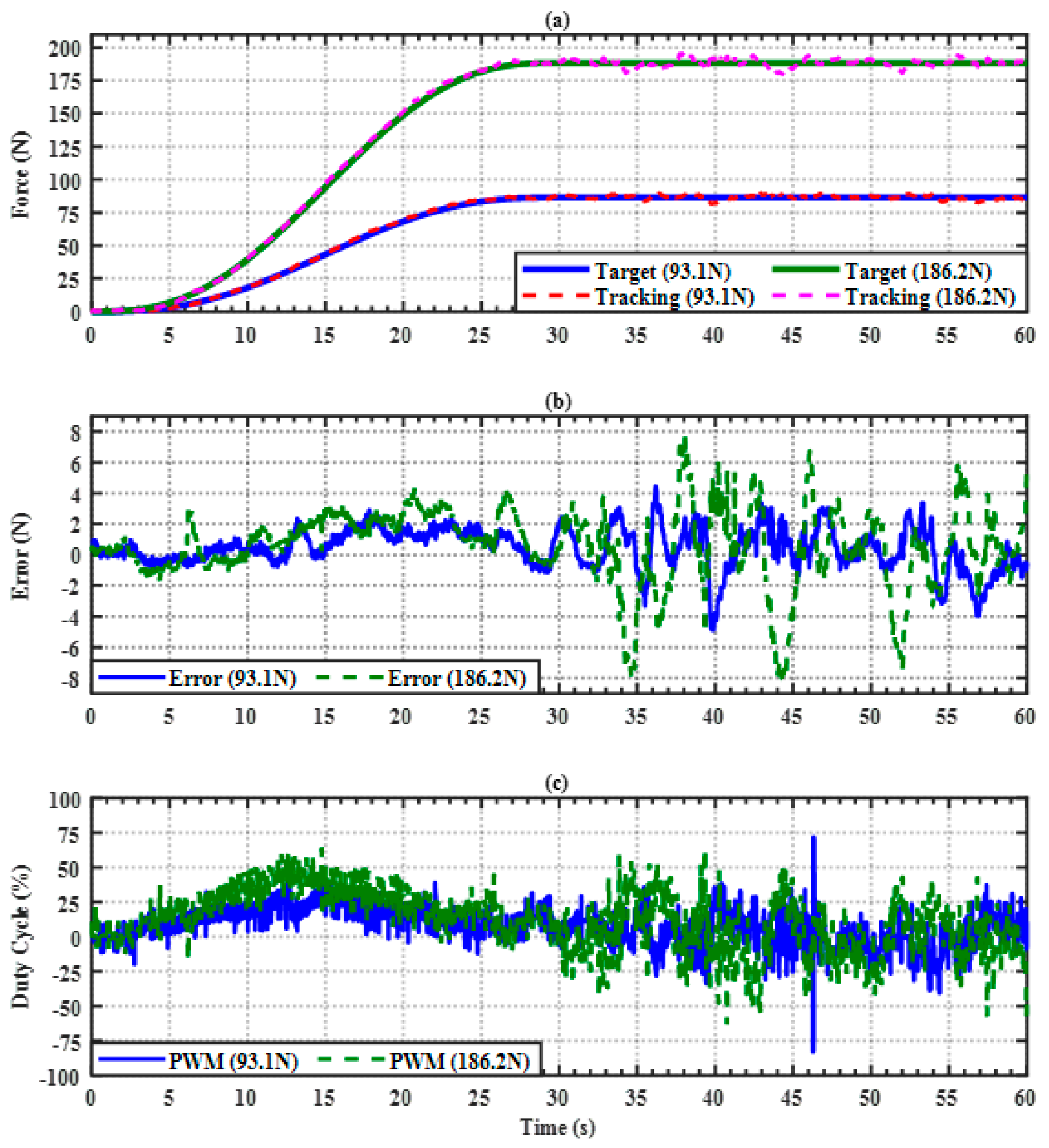
Figure 10.
The ideal gait trajectory of the lower limb in the sagittal plane. (a) The ideal joint trajectory of the knee; (b) the ideal joint trajectory of the hip joint.
Figure 10.
The ideal gait trajectory of the lower limb in the sagittal plane. (a) The ideal joint trajectory of the knee; (b) the ideal joint trajectory of the hip joint.
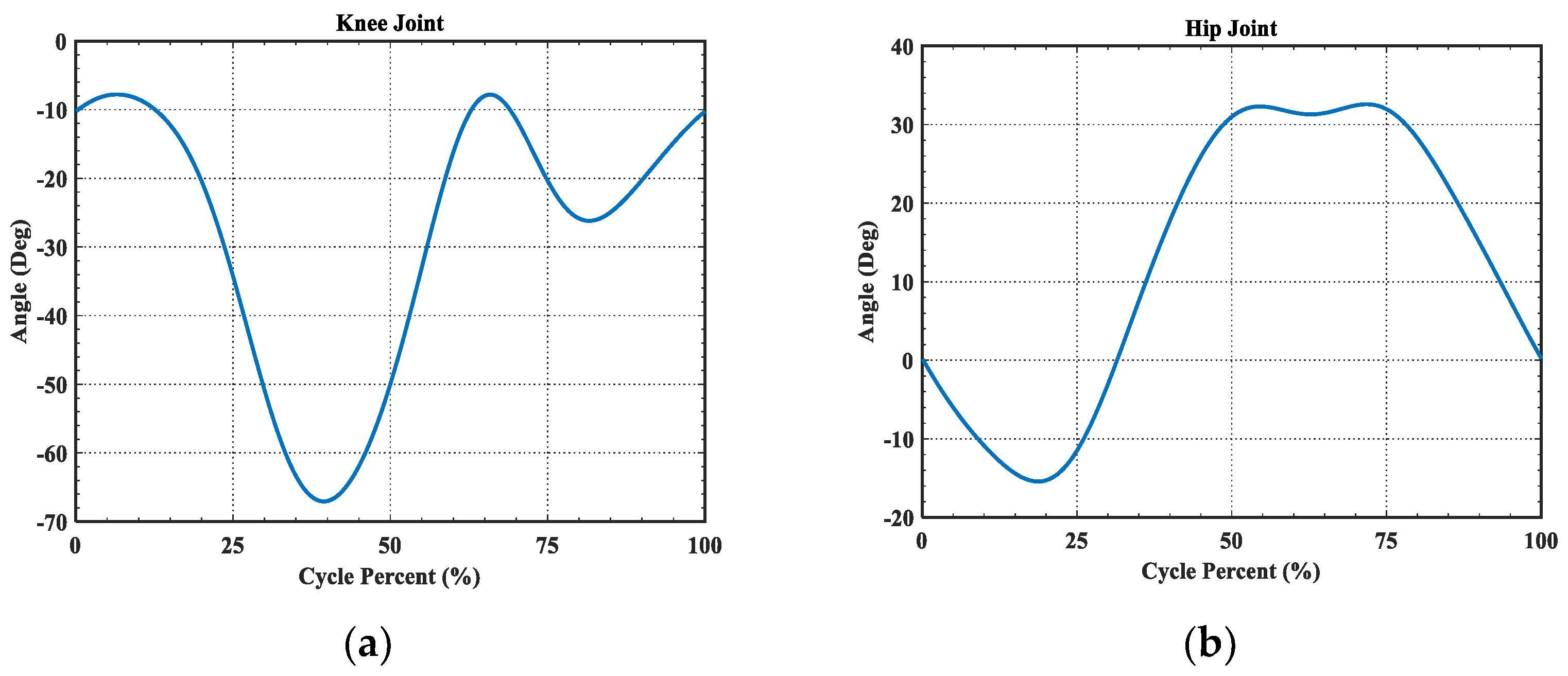
Figure 11.
Single joint control block of the LES.

Figure 12.
Right knee joint trajectory tracking for LES with the ILESO−PSMC. (a) Knee joint angle tracking response; (b) knee joint angle tracking error; (c) current control signal.
Figure 12.
Right knee joint trajectory tracking for LES with the ILESO−PSMC. (a) Knee joint angle tracking response; (b) knee joint angle tracking error; (c) current control signal.
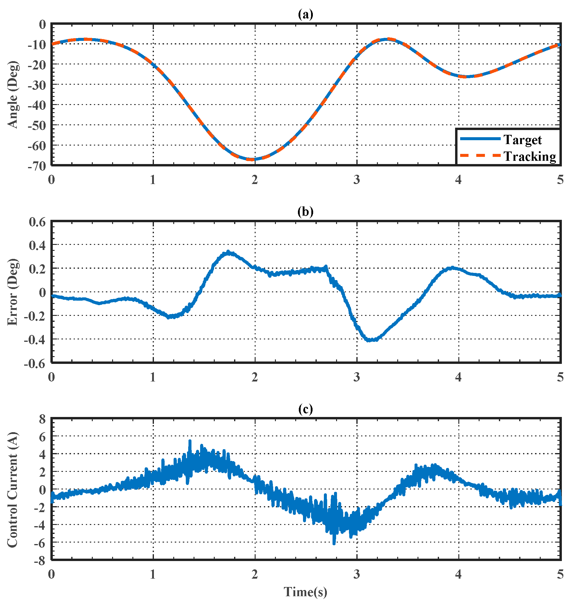
Figure 13.
Right hip joint trajectory tracking for LES with the ILESO−PSMC. (a) Hip joint angle tracking response; (b) hip joint angle tracking error; (c) current control signal.
Figure 13.
Right hip joint trajectory tracking for LES with the ILESO−PSMC. (a) Hip joint angle tracking response; (b) hip joint angle tracking error; (c) current control signal.

Figure 14.
Dynamic bodyweight unloading force control of ILESO−PSMC, 20% (137.2 N) of participant body weight (686 N). (a) Unloading force tracking response; (b) unloading force tracking error; (c) duty cycle of PWM.
Figure 14.
Dynamic bodyweight unloading force control of ILESO−PSMC, 20% (137.2 N) of participant body weight (686 N). (a) Unloading force tracking response; (b) unloading force tracking error; (c) duty cycle of PWM.
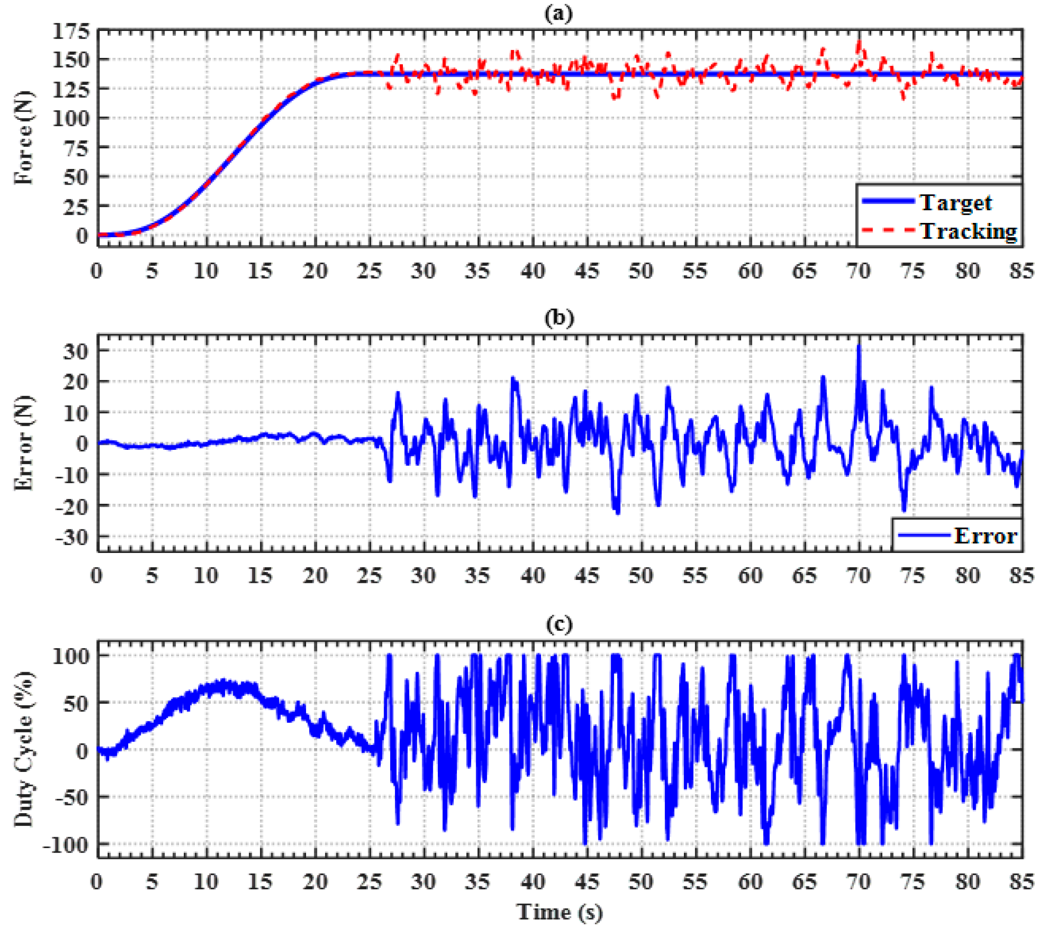
Figure 15.
Right hip joint trajectory tracking for LES during the overground gait training with the ILESO−PSMC. (a) Hip joint angle tracking response; (b) hip joint angle tracking error; (c) current control signal.
Figure 15.
Right hip joint trajectory tracking for LES during the overground gait training with the ILESO−PSMC. (a) Hip joint angle tracking response; (b) hip joint angle tracking error; (c) current control signal.
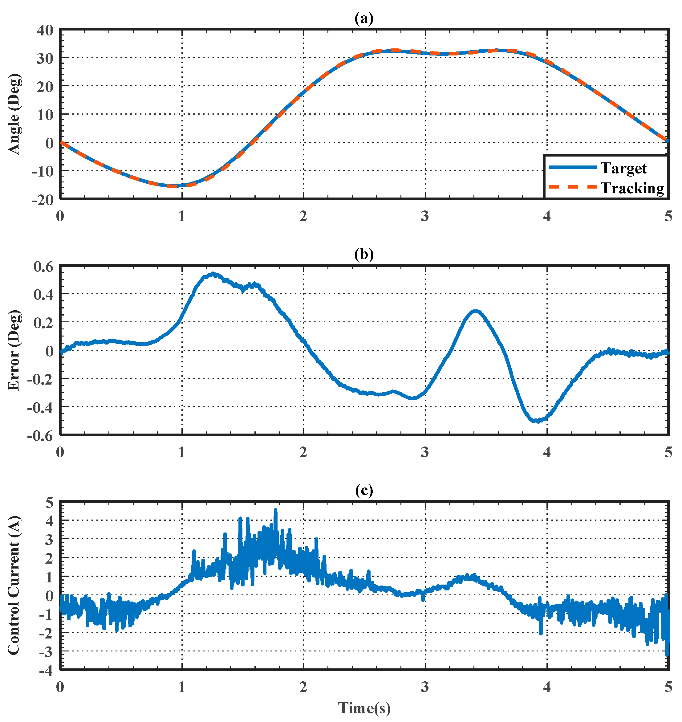
Figure 16.
Right knee joint trajectory tracking for LES during the overground gait training with the ILESO−PSMC. (a) Knee joint angle tracking response; (b) knee join angle tracking error; (c) current control signal.
Figure 16.
Right knee joint trajectory tracking for LES during the overground gait training with the ILESO−PSMC. (a) Knee joint angle tracking response; (b) knee join angle tracking error; (c) current control signal.
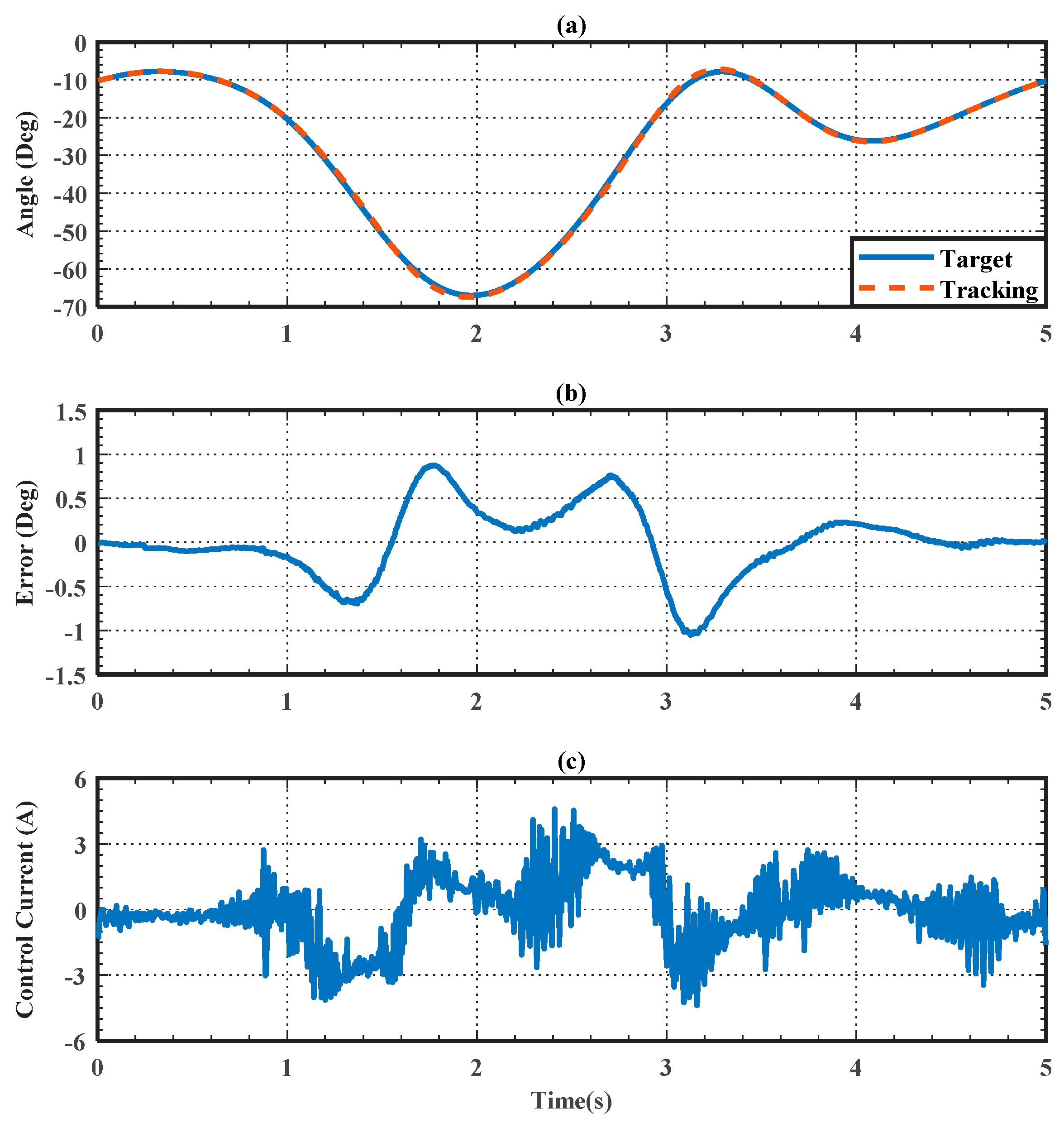
Figure 17.
Discontinuity recovery safety test using PID and ILESO−PSMC. (a) Joint angle tracking response; (b) joint angle tracking error; (c) current control signal.
Figure 17.
Discontinuity recovery safety test using PID and ILESO−PSMC. (a) Joint angle tracking response; (b) joint angle tracking error; (c) current control signal.


Table 1.
Parameters of the ILESO-PSMC with PWM for the AMBSS experiment.
| Control parameters | ||||||
| 15 | 5 | 10 | 7 | 9 | 15 |
Table 2.
Parameters of the ILESO-PSMCs for the LES experiment.
| Control parameters | Joint | ||||||
| Hip | 400 | 5 | 800 | 5 | 5 | 3000 | |
| Knee | 600 | 10 | 2000 | 10 | 10 | 3000 |
Publisher’s Note: MDPI stays neutral with regard to jurisdictional claims in published maps and institutional affiliations. |
© 2022 by the authors. Licensee MDPI, Basel, Switzerland. This article is an open access article distributed under the terms and conditions of the Creative Commons Attribution (CC BY) license (https://creativecommons.org/licenses/by/4.0/).
Share and Cite
MDPI and ACS Style
Lee, L.-W.; Li, I.-H.; Lu, L.-Y.; Hsu, Y.-B.; Chiou, S.-J.; Su, T.-J. Hardware Development and Safety Control Strategy Design for a Mobile Rehabilitation Robot. Appl. Sci. 2022, 12, 5979. https://doi.org/10.3390/app12125979
AMA Style
Lee L-W, Li I-H, Lu L-Y, Hsu Y-B, Chiou S-J, Su T-J. Hardware Development and Safety Control Strategy Design for a Mobile Rehabilitation Robot. Applied Sciences. 2022; 12(12):5979. https://doi.org/10.3390/app12125979
Chicago/Turabian StyleLee, Lian-Wang, I-Hsum Li, Liang-Yu Lu, Yu-Bin Hsu, Shean-Juinn Chiou, and Te-Jen Su. 2022. "Hardware Development and Safety Control Strategy Design for a Mobile Rehabilitation Robot" Applied Sciences 12, no. 12: 5979. https://doi.org/10.3390/app12125979
Note that from the first issue of 2016, this journal uses article numbers instead of page numbers. See further details here.