
A Study on the Dynamic Behavior of a Sieve in an Industrial Sifter


1
Faculty of Process and Environmental Engineering, Lodz University of Technology, 93-005 Lodz, Poland
2
Institute of Materials Science and Engineering, Lodz University of Technology, 90-537 Lodz, Poland
3
Department of Vehicles and Fundamentals of Machine Design, Lodz University of Technology, 90-537 Lodz, Poland
*
Author to whom correspondence should be addressed.
Appl. Sci. 2022, 12(17), 8590; https://doi.org/10.3390/app12178590
Submission received: 1 July 2022
/
Revised: 24 August 2022
/
Accepted: 24 August 2022
/
Published: 27 August 2022
Abstract
:Various vibrating screens are often applied in various industries, e.g., mining, agriculture, and others. The complex shapes of the screen trajectories in the oscillating motion strongly affect the best processing properties of such machines. One of the possible methods for obtaining such complex shapes is the application of double-frequency vibrators on such screens. The goal of the present study was to analyze the dynamical behavior of the prototype sifter sieve elaborated. The simulation model of such a sifter sieve and the research stand for studies on its sifter trajectories were elaborated. Simulations of sifter motion were conducted, and their results were compared with those obtained from measurements on the research stand. The recommendations as to the frequency ratio of vibrators enabling obtaining a high complexity of sieve movement have been formulated and included in the paper. Particularly, the multiple of the value equal to one third for the ratio of angular velocities under their reverse synchronization for two rotary vibrators exciting the screen analyzed was the best among all analyzed values of such a ratio.
1. Introduction
Vibrating screens, conveyors, rammers, and other bulk material processing machines are often applied in mining, metallurgical, construction, and other industries [1].
It is widely known that the shape of the trajectory of the screen during its vibrations strongly affects reaching the best processing properties of the machine. For example, in the case of vibrating screens used for coal preparation, the screen motion can be circular, elliptical, or in a straight line. The linear one is used on horizontal, high-frequency, and banana screens. An elliptical one can also be applied on horizontal and banana screens [2]. To explain, the banana screen utilizes a curved banana-shaped deck instead of a flat deck fitted with a horizontal screen [2]. The elliptical motion is claimed to allow higher capacities and efficiencies over both linear and circular motion machines [3].
The trajectories of vibrational motion leading to the intense segregation of the grain layer moving on the sieve have been investigated for a long time.
Using the stationary grain thresher elaborated, Simonyan and Yiljep [4] investigated grain separation and cleaning efficiency distribution of the cleaning unit, fractionated by sieve and horizontal air stream, along the sieve length. They studied the effect of feed rate, air speed, and sieve oscillation frequency on the cleaning efficiency of sorghum. They found that cleaning efficiency weakened with the enhancement of sieve oscillations frequency and feed rate. Simultaneously, cleaning loss was enhanced with the rise of such frequency, feed rate, and air speed.
According to [5], the more complicated the kinematic of oscillating sieves, the more the agents influence the efficacy of the screening process. Their negative effect becomes more severe with the wear and ageing of their mechanical components [6,7,8].
The drive of the various vibrating machines presented in [9,10,11,12,13] was based on a traditional scheme with a converter of rotating motion into a reciprocating one. The complicated kinematic scheme of such a drive enhanced the cost of the machine, simultaneously weakening energy efficacy and reliability due to many rubbing and wearing surfaces engaged. Vyngra et al. [14] found that in such type of drive the metal consumption and energy losses were enhanced because inertial flywheels were introduced to alleviate periodic force pulses.
Yarullin et al. [15] elaborated on the vibrator with the regulated frequency and amplitude of oscillations using counterbalances. In this paper, the regulation is suggested to be realized at the cost of even more complex kinematics, i.e., the use of supplementary spring-loaded counterbalances.
Linenko et al. [16] realized the complex oscillation using the normal force of a plane linear asynchronous motor (LAM). They elaborated an adaptive LAM control system allowing stabilizing of the vibrational parameters of the sieve mill. LAM allowed direct receiving movement of the operating body and an energy-effective electric drive of vibrations with their regulated parameters together with the elastic components.
Despite LAMs, the other electric drives can force reciprocating motion.
Chen et al. [17] elaborated on a linear reciprocating pulse jet engine and proposed its application in cooling compressors.
According to [18], linear electromagnetic transducers are often applied in vibration devices. The authors mathematically modelled an electromechanical structure with reciprocating motion of bodies linked by spring bonds and stimulated by a drive coil.
Solomin and Chekhova [19], proposed changing the resistance of the secondary LAM component and controlling the speed with starting and traction forces. The resistance was modified via a movable element shorting a various number of windings in each groove.
According to [5], the adjustable linear induction motors (LINs) are applicable as traction machines for magnetic levitation transport. However, in electric drives with reciprocating motion of the operating parts in the vibration frequency range of the sieves of grain cleaning machines, the constant changing of the resistance of the secondary element circuit in a suggested way was not advised, as such a method led to enhanced wear of the rubbing components and further resistance to motion.
Aipov et al. [5] studied the structural and technological parameters and vibrational modes of a sieve mill driven by a LIN.
Material accumulation on the linear vibrating screen surface is preferably unwanted [20]. However, the screening process is sometimes associated with the purification of the particles from the residues of the previous process, for example, by surrounding the granular cores with further functional layers. Then, the intensity of mixing the grains remaining on the sieve and the correct selection of this intensity to the required properties of the final screening product becomes of particular importance.
The mass of material remaining on the vibrating sieve is subject to intensive mixing, which is a complex process. However, it is possible to indicate, at least qualitatively, two sources of the impact that positively affect this process. The grains of the screened material lying on the screen are subject to the force of gravity, frictional and elastic effects from the adjacent grains and the surfaces of the screen or its frame, as well as the inertia forces. During vertical oscillations of the sieve, practically for every single grain located in the mass of material remaining on the sieve, its potential energy is converted into kinetic energy and vice versa. At the same time, the frictional and deformation effects from adjacent grains may cause its time-delayed linear and rotational displacements relative to the screen and adjacent grains. The resulting motion of the grain set promotes the mixing of the mass of material remaining on the screen. Time-delayed grain displacements can also occur under horizontal screen oscillations. Then, the frictional forces from the screen surface and the deformation forces from the screen frame acting on the grains adjacent to them have a decisive influence on such displacements. These interactions are then transferred to successive adjacent grains due to the frictional and deformation interactions therebetween. As a result, additional time-delayed resultant linear and rotational displacements of grains appear in the mass of material remaining on the screen, which intensifies the mixing of this material. The friction forces most often depend non-linearly on the changes in grain velocities during the performance of relative grain displacements, and to a lesser extent on the grain displacements associated with changes in the local values of the friction coefficient. Inertia forces are directly proportional to changes in grain velocities. Therefore, the mixing intensity of the screened material is proportional to the intensity of the sieve velocity changes.
An important problem affecting the screening efficacy is sieve blocking. According to [21] screens with the continuous vibrational motion of sieves caused a fall-out of blocked particles, i.e., the phenomenon of sieve self-purification. The more intense motion allowed an easier sieve self-purification. Moreover, Lawinska and Modrzewski [22] showed that for higher frequency and higher amplitude of vibrations the screens with vibrating sieves exhibited a lower tendency to sieve hole blocking.
Li et al. [23,24] reported that the enhancement of vibration intensity increased the screening efficiency of materials to a certain extent but simultaneously enhanced the loss of materials during the screening process.
During studies on the accuracy of the vibratory screening of materials with various particle sizes and shapes, Elskamp and Harald [25,26] found that when the horizontal velocity component of the material was stronger than the vertical one, the screening accuracy was higher; otherwise, it was weakened.
Yan et al. [27] reported that the best screening accuracy of the portable linear vibrating screen could be obtained for the excitation frequency in the range from 18 Hz to 20 Hz, and for the particles’ mass flow rate below 0.4 kg/s.
To implement the advised complex movement of the sieve, enabling better mixing of the screened material remaining on it, with the simultaneous possibility of adjusting the amplitude and frequency of sieve vibrations and without interfering with the resistances of the secondary elements of the circuits of the applied vibrators, a double frequency prototype sifter sieve was developed. During its design process, efforts were made to limit the number and complexity of the spatial structure of the movable parts of the screen. This was achieved by using two simple rotary vibrators which theoretically could be moved unidirectionally continuously, but typically their position was relative to the screen to obtain the desired screen vibration frequency configuration. The vibrators could achieve a frequency of at least 20 Hz. The amplitude of vibrations was easily regulated and determined by changing the rotational speed of vibrators with the help of inverters. The shifting of the vibrators relative to the screen took place beyond the stage of performing the working vibrations of the screen and did not affect the screening process. The study aimed to analyze the dynamical behavior of such a sifter sieve.
Such a prototype screen combines the advantages of a shaking screen and a vibrating one. In the case of a shaking screen, the particle mass can slide smoothly over the screen without bouncing, promoting the easy pass through the sieve openings for the stratified undersize particles [28]. In a vibrating screen, the occurring lifting and dropping effect of grains expands the material bed and limits their passing through the sieve openings. However, the strong normal force component limits progressive sieve blinding, and the turbulent expansion of the material bed prevents packing. Such advantages become increasingly important with enhancing bed depth and particle size. Additionally, the screen inclination can be used for better movement of the screened material relative to the screen surface [28].
By adjusting the proportion of vertical and horizontal amplitude in the resultant vibratory motion of the screen in the prototype screen, the optimal course of the screening process can be obtained from the point of view of limiting the screen blockage and the assumed structure of the screened material and the screen energy efficiency.
2. Multi-Frequency Vibrating Screens
Free vibrating screens are characterized by spatial, non-linear vibrating motion of the sieves. The riddles of these machines have six degrees of freedom and can vibrate longitudinally in all three directions in space, as well as torsionally around three mutually perpendicular axes. This is due to both the drive system, constructed to provide the stimulating forces in selected directions, and the suspension system, having different susceptibility to elastic deformation for all six degrees of freedom. Hence, the other name of these machines: screens with spatial sieve movement. Such machines are designed to achieve the three-dimensional movement of the screens to ensure the most favourable screening process. They are driven by at least two independent driving vibrators, not mechanically synchronized using a gear, but operating on the principle of dynamic self-synchronization. This creates an opportunity to apply different frequencies of stimulating forces in individual drive units. Therefore, we can talk about two-, three-, or multi-frequency screens.
The mentioned vibrators can be in the form of the inertial ones, widely used in vibration machines, such as screens, vibration mills, granulators, or crushers [1,29,30,31,32,33,34,35].
For screening of fine wet particles or near-aperture particles, Peng et al. [36] elaborated a cantilevered vibrating sieve (CVS) with open screen holes, composed of cantilevered sieve rods. Such a sieve exhibited a higher screen-penetrating probability than traditional sieves. The authors reported that additional vibrations emerged during the screen body motion, and a lower difference between the natural circular frequency and the vibration frequency can cause a higher vibration amplitude of the cantilevered sieve rod.
The vibrating sieves often comprised various springs affecting their motions. Liu et al. [37] reported that spring failures cause structural damage and low screening efficiency of mining vibrating screens. Therefore, spring failures should be effectively diagnosed to prompt maintenance for the safety and reliability of such screens.
2.1. Linear-Elliptical Double-Frequency Sifter
Obtaining intensive segregation of feed grains is possible thanks to the use of, among others, two-frequency screens, which give better process indicators compared to classic screens, currently used, for example, in the mining industry. The sieve movement paths obtainable with a two-speed screen favour the intensive course of the process of mixing the granular layer on the sieve. Dual frequency screens feature two different rotational speed vibrators that drive these machines. Sifters belonging to this group have at least two rotary vibrators.
The diagram of the exemplary configuration of the double-frequency screen is shown in Figure 1. It shows a horizontally supported variant, but the machine can also be inclined to the horizontal at an angle α of up to 300, as well as freely suspended from the spring suspension. To drive such a screen, two rotary vibrators with identical or different static moments of inertia are used.
An important parameter characterizing the operation of a double-frequency screen is the speed transmission coefficient defined by Equation (1).
Such a parameter quantity determines how much the angular velocities ω1 and ω2 (or rotational n1 and n2) of two rotary vibrators differ from each other. Depending on the applied speed transmission coefficient, different paths of motion of the vibrating machine can be obtained. In the case of double-frequency screens, it is important to properly configure the drive system, understood as the appropriate selection of dimensions: l1 and l2, as well as h1 and h2 (Figure 1). Too large values of distances l1 and l2 mean that in the movement of the riddle, the torsional movement around the center of gravity S0 is important, resulting in large amplitudes at the beginning and end of the screen. In this case, the screen center amplitudes are small. The screening material layer will then be rolled up within the central part of the screen. Such a course of the screening process is unacceptable, as excess material may spill through the sidewalls of the screen. As a partial solution to this problem, an additional increased horizontal inclination of the screen can be made.
The axis perpendicular to the line connecting the centers of masses of both vibrators is the so-called kinematic axis of the machine. It can be vertical, e.g., OK1, in the case of vibrators placed extremely and symmetrically at both ends of the riddle, or inclined at any angle β, e.g., OK2, in the case of shifting the vibrators relative to each other by the appropriate values h1 and h2 as well as l1 and l2. The angle β is called the screen path fluctuation angle because, in the case of counter-rotating and equal frequency of excitations on both vibrators, it allows to obtain straight-line vibrations inclined at this angle. In the case of concurrent synchronization at the same frequencies, we usually get an elliptical motion in which the main axis of the ellipse is tilted to the horizontal at the angle β.
2.2. Prototype Double-Frequency Sifter
The prototype screen analyzed in the present study used a structure suspended freely on a spring suspension and equipped with two rotary inertia vibrators located above and below the riddle.
The design of the prototype screen (Figure 2) enabled the adjustment of all basic parameters of the machine operation such as:
- The inclination of the riddle in respect to the horizontal.
- Positioning the motors in respect to the center of the riddle.
- The excitation forces induced by the engines.
- Engine rotational speeds.
The screen structure made it possible to change the setting of the vibrators by moving them apart relative to the center of the riddle, usually symmetrically, i.e., the same for both vibrators, only in opposite directions (Figure 3). The change in the spacing of the vibrators resulted in a change in the values of the screen fluctuation paths.
The screen was able to regulate the stimulating force of individual driving vibrators. It was done by changing the position of unbalanced masses on the shaft of a given vibrator. There are unbalanced masses at both ends of the vibrator shaft. There is a mass at each end of the vibrator shaft consisting of two exact parts. To modify the stimulating force, one mass was shifted apart relative to the other by an appropriate angle. The engine rotational speed was regulated with the use of inverters. This made it possible to obtain different combinations of the rotational frequencies of both vibrators. The maximum rotational frequency ωmax of the vibrators used was 1500 rpm, which is the standard rotational speed of most currently produced drive systems of this type.
3. Materials and Methods
3.1. The Physical Model of the Two-Frequency Screen Used for Simulation
The double-frequency screen analyzed comprised two driving vibrators and a rectangular riddle mounted on a spring suspension. The design allowed for changing the riddle’s inclination by the angle within the range of 0–20° and for changing the spacing of the vibrators (Figure 4). The corresponding direction of vibration main components along the OK axis was inclined by the angle . Position 1 was related to the top vibrator, while position 2 was to the bottom one. The centers of both vibrators could be displaced, independently of each other, relative to the point along the riddle operating plane. As shown in Figure 4, such displacements were equal to:
- The distance corresponding to position 4 and limited by maximum left distance corresponding to position 5.
- The distance corresponding to position 3 been limited by the maximum right distance corresponding to position 6.
In Figure 4, positions 3–6 are shown for the case of the inclined riddle. The module of distances and are often equal.
Moreover, the screen vibrators could operate under conditions of dynamic self-synchronization: concurrent or counter-rotating with any rotational speed, different for both vibrators. This allowed to obtain hugely different paths of vibrating motion.
3.2. Determination of Equations of Motion
The equations of motion of the sieve body were obtained using the principle of virtual work [38].
The position of equilibrium of the screen body in the center of mass S0 was related to a right-handed system of x, y, and z coordinates (Figure 5). Relative to such a system, the screen body has 6 degrees of freedom in space. However, due to the lack of stimulating forces acting in the z-direction, the considered system was limited to the XY plane transverse to the operating plane of the screen (perpendicular to Figure 5). The damping in the considered system was omitted. The angles of rotation of the solid around the transverse axis z are denoted by .
The subject of the considerations is the movement of the center of mass of the screen body with the mass M and the moment of inertia for the transverse axis (z) equal to . The screen is suspended by a set of four identical springs with vertical stiffness and longitudinal stiffness .
The derivation of the equations was conducted in two stages. Initially, the system did not consider the forces forcing motion and it was first considered as a system for free vibrations.
The system of free motion equations of the sifter body based on Newton’s second law of dynamics in the matrix notation has the Equation (2).
where:
= inertia matrix of the system under consideration [kg],
= matrix of elasticity of the system [N/m],
= vector of displacements of the screen body [m].
Equation (2) is a homogeneous form of the full equation of motion of the considered system, which is similar to that presented in [39]. To determine Equation (2), the screen body was deflected from the equilibrium position, giving it successively displacements following the positive signs of the individual six coordinates. The positions of the body after a deflection from the equilibrium position in three consecutive directions are marked in Figure 5 with different colored lines. Each deflection of the body from the equilibrium position is accompanied by the appearance of reaction forces in the elastic elements of the system. These forces and their moments determine the elements of the elastic matrix of the system in Equation (2).
The left sides of equations of motion (according to Figure 2) lead to Equations (3)–(5):
In the second stage of deriving the motion equations for the screen, the operation of electric motors generating centrifugal forces causing screen vibrations was considered. Let denote the vector of forces and moments of stimulating forces acting on the dynamical system under consideration. Then, the total equation of forced motion of the screen body has the Equation (6)
In the second stage of deriving the equations of motion, the vector components were determined. For this purpose, the principle of superposition was applied, adding, in turn, the stimulating forces from individual motors forcing the screen to move. This process is illustrated in Figure 6.
The right sides of the equations of motion (according to Figure 6) have the Equations (7)–(9).
On this basis, the set of equations of motion can be written in the Equation (10):
Equation (10) presented a set of three ordinary differential equations with constant non-homogeneous coefficients. The solution allowed determining the kinematic parameters of the screen movement.
The general solution of each component equation of the set of equations of motion (10) is the sum of the general solution of the homogeneous equation and the special solution of the full equation, as described in the Equation (11).
The general solution of the homogeneous equation represented free vibrations. These vibrations disappeared after the initial transition period due to damping, which was not considered in the mathematical model under consideration. The special solution of the full equation represented the forced vibrations of the system, which were the only ones in the steady state. Due to the existence of two, generally independent, centrifugal forces forcing the movement of the sifter and changing with frequencies and , respectively, the special solution of the full equation of motion was presented as a sum of special solutions with the frequencies and , as described in the Equation (12).
The set of Equations (10) describing the movement of the sifter can be written in the Equation (13).
where:
, , , , , , ,
The sum of the special solutions with the frequencies ω1 and ω2 was a special solution to the system of Equation (13). For the sifter under consideration, the final solution took the form of Equation (14).
The Equation (14) allowed simulating the riddle’s super-positioned motion of the screen studied using the numerically generated X-Y graphs.
3.3. The Research Stand
The experiments were conducted on the test unit (Figure 7).
The test unit comprised a cuboidal sieve elastically suspended to allow regulating the inclination angle in the range of 0–25 degrees. The studies on the test unit have been carried out for the angle values equal to 0, 10, 15, and 20°, respectively.
The vibrator setting can be modified (Figure 8) by its drawing aside a distance chosen against the central part of the sieve (an upper vibrator in the direction of the feeder, a bottom one in the direction of the end of the screen). Particularly, the four vibrator positions reached in the mentioned manner for the distance of 0, 110, 220, and 380 mm caused the oscillating sieve trajectory angle β with values equal to β1 = 0°, β2 = 27.5°, β3 = 42.2°, and β4 = 61°, respectively.
The stimulating force of the vibrator can be modified via the position shift of unbalanced masses on its shaft. Such a mass comprises two exact components. The modification of the stimulating force is realized through the separation of one component from another one by the chosen angle. The studies on the test unit have been usually carried out for three settings providing reaching:
- (a)
- Maximal stimulating force—2 N.
- (b)
- ½ of maximal stimulating force.
- (c)
- ¼ of maximal stimulating force.
Figure 9 shows schematically the rules of this modification.
The stimulating force was weakened in one vibrator of their pair on the test unit, i.e., in the one rotating at the nominal speed (1500 rpm), whereas the stimulating force was always maximal (2 kN) in the second vibrator rotating at the speed lower than the nominal one.
The speeds of vibrators ω realized during studies on the test unit have usually reached the following values:
- = 1500 rpm.
- 2/3 = 1000 rpm.
- 1/2 = 750 rpm.
- 1/3 = 500 rpm.
The modification of the vibrator speed was conducted using the inverters. Generally, 28 various sets of speed and vibrator rotation directions were achievable.
3.3.1. Measurement
The sieve vibration amplitudes were measured using the system schematically presented in Figure 10. It comprised the piezoelectric sensors, the integrating system, and a computer with a measurement card allowing data recording. The piezoelectric sensors were able to measure the vibration acceleration in the range 0–100 m/s2, for the frequency range 2–5000 Hz, and with the measurement resolution of 0.1 m/s2.
The use of four piezoelectric sensors mounted on the sieve provided the means obtain and record the data, which allowed further determining the actual sieve inclination. The sensors were mounted through their threaded ends on the sieve. Their measurement direction axes crossed around the screen center of gravity or at the extreme points of the sieve (Figure 11).
The tensional signals generated by the sensors subjected to vibrational accelerations were subsequently transferred to the integrating system. Therein, the signals were doubly integrated, and the resultant displacements allowed the determination of the actual inclination value of the sieve. Such signals were transferred via the measurement card to the computer memory for recording.
3.3.2. Parameter for Comparison of Results from Measurement and Simulation
To allow a comparison of motion intensities of center of screen analyzed obtained from the measurement and from simulation the one auxiliary parameter was elaborated. It was assumed that the thickness of the line of the path of successive points in the simulation is remarkably close to the thickness of the markers of successive positions of the point under consideration recorded during the measurement. Having the traffic path chosen represented by a line of the selected thickness and color, it can be possible to determine the number of pixels comprised by such a line. It is also possible to determine the total number of pixels comprised by the rectangle area, including such a traffic path. The mentioned parameter was the ratio of the area occupied by pixels of the path of the point relative to the area of the rectangle defined by the oscillation amplitudes in the X and Y directions, as given by Equation (15):
The number of pixels was determined using the Matlab R2021b (MathWorks, Natick, MA, USA) software toolbox utilized for the analysis of various image parameters.
4. Results and Discussion
4.1. Screen Trajectories Resulted from Simulation
Figure 12 and Figure 13 showed projections on the plane of the system of temporary positions of the screen’s center of gravity, according to the observation time. The set of instantaneous solid positions during the set period of motion created the traffic paths for the compatible (Figure 12) and the reverse (Figure 13) synchronizations, respectively. The data for the calculations were the parameters of the screen installed on the experimental stand, such as mass 150 kg, system stiffness in y and x directions: 21,712 N/m, mass moment of inertia relative to the z-axis, 110 kg m2, real geometrical dimensions of components involved during motion of the screen. The speed ratios of rotary drive vibrators (rpm) took the consecutive values, relating to the subcomponents of:
It was seen that in both cases of compatible and reverse synchronization that with a decrease of values of the ratio the shape of traffic paths became more complex compared to the case of . Interestingly, for a multiple of the ratio value equal to 1/3 such shapes contained more loops. Such increased complexity of traffic paths is advantageous as it translates into better sieving intensity and better mixing of the material on the sieve. Although during both types of synchronization for the case of the shape of the traffic path was elliptical, for compatible synchronization such an ellipse was significantly narrower along the X axis. Interestingly, the shape of the traffic path with two loops: the outer one and the inner one obtained for the compatible synchronization at the ratio was similar to the shape of the traffic path reported in [20] obtained for the case of , however for the double-frequency inertial vibrator of the other design. Additionally, for each case of , the shapes of traffic paths for compatible synchronization differed significantly from those for the reverse one.
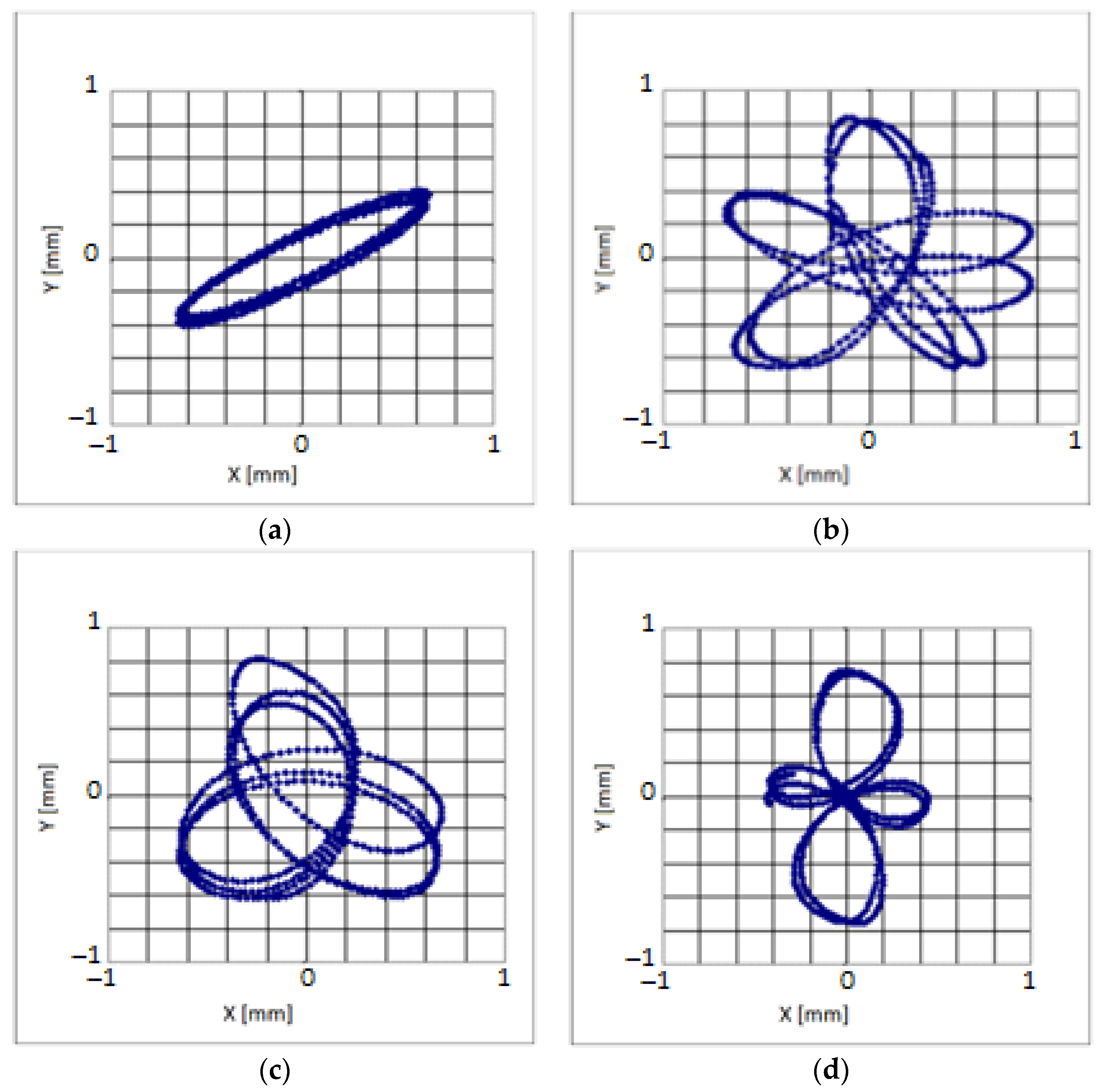
4.2. Results from Measurements
Figure 14 and Figure 15 showed examples of the paths of the riddle center movement for selected screen drive configurations, the same as for the computer simulation.
For compatible synchronization, the shapes of traffic paths of the screen center differed significantly from these obtained from simulation, particularly for the ratio value equal to 1/2 and 1/3. For the reverse synchronization, the shapes of traffic paths were more like those obtained from simulation than for the compatible simulation. For all cases of ratio values analyzed, it was visible the difference in oscillation amplitudes in the X and Y direction. For the case of ratio value equal to 1, the shape of trajectories pointed occurrence of the phase shift between oscillation amplitudes in the X and Y direction by about for the compatible synchronization and by about for the reverse synchronization. During the recording time of the measured position of the screen center, there were multiple deviations of the traffic paths from their stable (averaged) position. This could be caused by the presence of temporary additional local deformations of the screen frame, as opposed to the simulation, where the screen frame was assumed as a rigid body. It could also be influenced by the mechanical damping occurring in a real screen and the characteristics of the measurement paths, introducing time delays for signals measured by sensors, and then being transferred to the computer disk. For multiples of the ratio value equal to 1/3, the traffic paths obtained had shapes containing more loops, and for the ratio value equal to 1/2 more deviations from their stable (averaged) positions in comparison to the case of the ratio value equal to 1. Such increased complexity of traffic paths is beneficial as it translates into better sieving intensity and better mixing of the material on the sieve. The reverse synchronization gave the more intensive motion of the screen center than in the case of the compatible synchronization, which in turn may translate into better mixing of the screened material, especially in the middle part of the screen.
4.3. Comparison of Results from Measurement and Simulation
Table 1 shows the values of the ratio obtained from the simulation and the measurement for the compatible and the reverse synchronization, and various values of the ratio .
For the compatible synchronization, the values of the ratio obtained from measurement were 1.5–2.2-fold higher than those obtained from simulation. The maximum value was observed for the value of the ratio equal to 1 and the smallest one for the value of the ratio equal to 1/2. For the reverse synchronization, the values of the ratio obtained from the measurement were 1.1–2.4-fold higher than those obtained from simulation. The maximum value existed for the value of the ratio equal to 2/3 and the smallest one for the value of the ratio equal to 1. For both kinds of synchronization, the values of the ratio obtained from measurement were higher compared to those from simulation which could be due to the occurrence of complex relative displacements of individual points belonging to the real screen being an elastic body in comparison to the screen modelled as a rigid body during simulation. The complex displacements translated into the form of recorded vibrations of the screen analyzed.
Interestingly, for the reverse synchronization, the values of the ratio obtained from measurement were slightly higher than those obtained for compatible synchronization. Particularly, they were 1.026-fold higher for the value of the ratio equal to 2/3, 1.024-fold higher for that equal to 1/3, and 1.023-fold higher for that equal to 1/2, respectively. However, for the value of the ratio equal to 1/3, the value of the ratio obtained from measurement was 1.013-fold lower than that from simulation.
5. Conclusions
Based on the obtained results some conclusions were made.
- The multiple of the ratio value equal to 1/3 was beneficial as it increased the complexity of sieve traffic paths, translating into better sieving intensity and better mixing of the material on the sieves.
- The reverse synchronization can allow the more intensive motion of the screen center than in the case of the compatible synchronization, resulting in better mixing of the screened material, especially in the middle part of the screen.
- Given the local deformations of the screen frame, the mechanical damping occurring in the real screen, and the characteristics of the measurement paths, introducing time delays for signals measured by sensors can affect the shape complexity of the traffic paths of the screen center.
- The obtained measurement values of the ratio, being proportional to the motion intensity of the observed sieve point, were 1.5–2.2-fold higher for the compatible synchronization and 1.1–2.4-fold higher for the reverse one, respectively, compared to those obtained from simulation.
- For the reverse synchronization, the values of the ratio obtained from the measurement were slightly higher than those obtained for compatible synchronization.
- Future research directions may include the influence of changes in materials and geometrical parameters of the screen components on the obtained frequencies and forms of its natural vibrations and the changes in the control algorithm of devices forcing the vibrations of the screen dictated by them. In addition, more complex mathematical models of the sieve can be developed, considering either its discretization to the form of many rigid elements or treating it as a continuous flexible object. Typically, the use of such more complex models leads to the involvement of more computing power in numerical analyses.
Author Contributions
Conceptualization, R.M. and A.O.; methodology, R.M.; software, A.R.; validation, K.S. and A.R.; formal analysis, A.O.; investigation, K.S. and A.O.; resources, R.M.; data curation, A.R.; writing—original draft preparation, K.S.; writing—review and editing, A.R.; visualization, A.R.; supervision, A.O.; project administration, R.M.; funding acquisition, A.O. All authors have read and agreed to the published version of the manuscript.
Funding
This research received no external funding.
Institutional Review Board Statement
Not applicable.
Informed Consent Statement
Not applicable.
Data Availability Statement
Not applicable.
Conflicts of Interest
The authors declare no conflict of interest.
References
- Gursky, V.; Kuzio, I.; Krot, P.; Zimroz, R. Energy-Saving Inertial Drive for Dual-Frequency Excitation of Vibrating Machines. Energies 2021, 14, 71. [Google Scholar] [CrossRef]
- Kumar, D.; Kumar, D. Chapter 4—Coal Sizing. In Sustainable Management of Coal Preparation; Kumar, D., Kumar, D., Eds.; Woodhead Publishing: Walnut St Philadelphia, PA, USA, 2018; pp. 49–68. [Google Scholar] [CrossRef]
- Wills, B.A.; Finch, J.A. Chapter 8—Industrial Screening. In Wills’ Mineral Processing Technology, 8th ed.; Wills, B.A., Finch, J.A., Eds.; Butterworth-Heinemann: Oxford, UK, 2016; pp. 181–197. [Google Scholar] [CrossRef]
- Simonyan, K.J.; Yiljep, Y. Investigating grain separation and cleaning efficiency distribution of a conventional stationary rasp-bar sorghum thresher. Agric. Eng. Int. CIGR Ej. 2008, 10, 1–10. [Google Scholar]
- Aipov, R.; Linenko, A.; Badretdinov, I.; Tuktarov, M.; Akchurin, S. Research of the work of the sieve mill of a grain-cleaning machine with a linear asynchronous drive. Math. Biosci. Eng. 2020, 17, 4348–4363. [Google Scholar] [CrossRef]
- Giyevskiy, A.M.; Orobinsky, V.I.; Tarasenko, A.P.; Chernyshov, A.V.; Kurilov, D.O. Substantiation of basic scheme of grain cleaning machine for preparation of agricultural crops seeds. IOP Conf. Ser. Mater. Sci. Eng. 2018, 327, 042035. [Google Scholar] [CrossRef]
- Savinyh, P.; Sychugov, Y.; Kazakov, V.; Ivanovs, S. Development and theoretical studies of grain cleaning machine for fractional technology of flattening forage grain. In Proceedings of the 17th International Scientific Conference Engineering for Rural Development Engineering for Rural Development, Jelgava, Latvia, 23–25 May 2018; pp. 124–130. [Google Scholar]
- Vasylkovskyi, O.; Vasylkovska, K.; Moroz, S.; Sviren, M.; Storozhyk, L. The influence of basic parameters of separating conveyor operation on grain cleaning quality. INMATEH 2019, 57, 63–70. [Google Scholar] [CrossRef]
- Steponavičius, D.; Špokas, L.; Petkevičius, S. The influence of position of the first straw walkers section on grain separation. Agron. Res. 2008, 6, 377–385. [Google Scholar]
- Ma, L.; Song, X.; Wang, H.; Xu, X.; Han, T.; Guo, H. Screening Kinematics Analysis of Cleaning Organs, and Extractives. IOP Conf. Ser. Mater. Sci. Eng. 2018, 452, 042123. [Google Scholar] [CrossRef]
- Popov, I.P.; Chumakov, V.G.; Terentyev, A.D. Drive power reduction of sieve sorting machines. In Scientific and Technical Statements of St. Petersburg State Polytechnic University; St. Petersburg State Polytechnic University: St. Petersburg, Russia, 2015; Volume 2, pp. 175–181. [Google Scholar]
- Shevtsov, I.V.; Beznosov, V.A. Drive unit for sieve mills of grain cleaning machines. Agrar. Vestn. Ural. 2014, 2, 43–45. [Google Scholar]
- Aradwad, P.P.; Sinha, J.P.; Kumar, T.V.A.; Yadav, R.S.; Samuel, D.V.K. Development of solar powered screen cleaner. Indian J. Agric. Sci. 2018, 88, 1914–1919. [Google Scholar]
- Vyngra, A.V.; Avdeyev, B.A.; Abdurakhmanov, R.F.; Yenivatov, V.V.; Ovcharenko, I.K. Mathematical model of start for a piston compressor electric drive of a ship refrigerator. In Proceedings of the 2019 IEEE Conference of Russian Young Researchers in Electrical and Electronic Engineering, ElConRus, St. Petersburg, Russia, 28–31 January 2019; pp. 373–376. [Google Scholar]
- Yarullin, R.; Aipov, R.; Gabitov, I.; Linenko, A.; Akchurin, S.; Mudarisov, S.; Khasanov, E.; Rakhimov, Z.; Masalimov, I. Adjustable driver of grain cleaning vibro-machine with vertical axis of eccentric masses rotation. J. Eng. Appl. Sci. 2018, 13, 6398–6406. [Google Scholar] [CrossRef]
- Linenko, A.V.; Gabitov, I.I.; Baynazarov, V.G.; Tuktarov, M.F.; Aipov, R.S.; Akchurin, S.V.; Kamalov, T.I.; Badretdinov, I.D.; Leontiev, D.S.; Vokhmin, V.S. The mechatronic module “linear electric drive—sieve boot” intelligent control system of grain cleaner. J. Balk. Tribol. Assoc. 2019, 25, 708–717. [Google Scholar]
- Chen, L.; Li, D.; Zhao, J. Control of a linear reciprocating switched reluctance motor for compressors. In Proceedings of the 14th IEEE Conference on Industrial Electronics and Applications, ICIEA, Xi’an, China, 19–21 June 2019; pp. 2003–2008. [Google Scholar]
- Neyman, L.A.; Neyman, V.Y. Dynamic model of a vibratory electromechanical system with spring linkage. In Proceedings of the 2016 11th International Forum on Strategic Technology, IFOST, Novosibirsk, Russia, 1–3 June 2016; pp. 23–27. [Google Scholar]
- Solomin, A.V.; Chekhova, A.A. Magnetic field and current displacement in groove of secondary element of adjustable linear induction motor. In Proceedings of the 2019 International Ural Conference on Electrical Power Engineering, UralCon, Chelyabinsk, Russia, 1–3 October 2019; pp. 271–276. [Google Scholar]
- Luoyang Haiside Heavy Industry Co., Ltd. What Are the Reasons for the Mixing of the Linear Vibrating Screen? Causes and Solutions. 2021. Available online: https://www.hsd-industry.com/news/reasons-for-mixing-of-linear-vibrating-screen/ (accessed on 17 August 2022).
- Szymanski, T.; Wodzinski, P. Characteristics of Screening in Screens with Vibrating Sieves. Physicochem. Probl. Miner. Process. 2005, 39, 177–188. [Google Scholar]
- Lawinska, K.; Modrzewski, R. Analysis of sieve holes blocking in a vibrating screen and a rotary and drum screen. Physicochem. Probl. Miner. Process. 2017, 53, 812–828. [Google Scholar]
- Li, H.; Li, Y.; Guo, F.; Zhao, Z.; Xu, L. CFD–DEM simulation of material motion in air-and-screen cleaning device. Comput. Electron. Agric. 2012, 88, 111–119. [Google Scholar] [CrossRef]
- Li, H.; Li, Y.; Tang, Z.; Xu, L.; Zhao, Z. Numerical simulation and analysis of vibration screening based on EDEM. Trans. CSAE 2011, 27, 117–121. [Google Scholar] [CrossRef]
- Elskamp, F.; Kruggel-Emden, H. DEM simulations of screening processes under the influence of moisture. Chem. Eng. Res. Des. 2018, 136, 593–609. [Google Scholar] [CrossRef]
- Elskamp, F.; Kruggel-Emden, H. Extension of process models to predict batch screening results under the influence of moisture based on DEM simulations. Powder Technol. 2019, 342, 698–713. [Google Scholar] [CrossRef]
- Yan, H.; Li, Y.; Yuan, F.; Peng, F.; Yang, X.; Hou, X. Analysis of the Screening Accuracy of a Linear Vibrating Screen with a Multi-layer Screen Mesh. Stroj. Vestn. J. Mech. Eng. 2020, 66, 289–299. [Google Scholar] [CrossRef]
- Sullivan, J.F. Screening Theory and Practice; Triple/S Dynamics: Dallas, TX, USA, 2012. [Google Scholar]
- Gursky, V.; Krot, P.; Korendiy, V.; Zimroz, R. Dynamic Analysis of an Enhanced Multi-Frequency Inertial Exciter for Industrial Vibrating Machines. Machines 2022, 10, 130. [Google Scholar] [CrossRef]
- Moncada, M.M.; Rodriguez, C.G. Dynamic Modeling of a Vibrating Screen Considering the Ore Inertia and Force of the Ore over the Screen Calculated with Discrete Element Method. Shock Vib. 2018, 2018, 1714738. [Google Scholar] [CrossRef]
- Sidor, J. A Mechanical Layered Model of a Vibratory Mill. Mech. Control 2010, 29, 138–148. [Google Scholar]
- Tomach, P. An attempt to increase technological capabilities of laboratory vibratory mills by changing the construction of chamber. New Trends Prod. Eng. 2019, 2, 195–205. [Google Scholar] [CrossRef]
- Feliks, J.; Krawczyk, M. Modeling the movement of broadcast on the concentration table. New Trends Prod. Eng. 2019, 2, 304–311. [Google Scholar] [CrossRef]
- Feliks, J.; Mitura, A.; Marciniak−Kowalska, J. Analysis of possibilities of application of vibratory cluster−producing device to alternative fuel production. Pol. J. Environ. Stud. 2013, 22, 12–17. [Google Scholar]
- Neikov, O.D. Chapter 2—Mechanical Crushing and Grinding. In Handbook of Non-Ferrous Metal Powders; Neikov, O.D., Naboychenko, S.S., Murashova, I.V., Gopienko, V.G., Frishberg, I.V., Lotsko, D.V., Eds.; Elsevier: Amsterdam, The Netherlands, 2009; pp. 47–62. [Google Scholar] [CrossRef]
- Peng, L.; Feng, H.; Wang, Z.; Wang, H.; Yang, H.; Huang, H. Screening Mechanism and Properties of a Cantilevered Vibrating Sieve for Particles Processing. Appl. Sci. 2019, 9, 4911. [Google Scholar] [CrossRef]
- Liu, Y.; Meng, G.; Suo, S.; Li, D.; Wang, A.; Cheng, X.; Yang, J. Spring Failure Analysis of Mining Vibrating Screens: Numerical and Experimental Studies. Appl. Sci. 2019, 9, 3224. [Google Scholar] [CrossRef] [Green Version]
- Lanczos, C. The Variational Principles of Mechanics. Dover Books on Physics; Dover Publications: Mineola, NY, USA, 2012; p. 464. [Google Scholar]
- Nguyen, V.X.; Golikov, N.S. Analysis of material particle motion and optimizing parameters of vibration of two-mass GZS vibratory feeder. IOP Conf. Ser. J. Phys. 2018, 1015, 052020. [Google Scholar] [CrossRef]
Figure 1.
Diagram of the exemplary realization of the double-frequency sifter.

Figure 2.
Prototype double-frequency sifter—main dimensions. 1, 2—movable rotary vibrators, 3—screen, 4, 5—springs.
Figure 2.
Prototype double-frequency sifter—main dimensions. 1, 2—movable rotary vibrators, 3—screen, 4, 5—springs.

Figure 3.
Prototype double-frequency sifter-variants of the arrangement of vibrators.

Figure 4.
Possible layouts of the axes of rotary vibrators in the double-frequency screen.
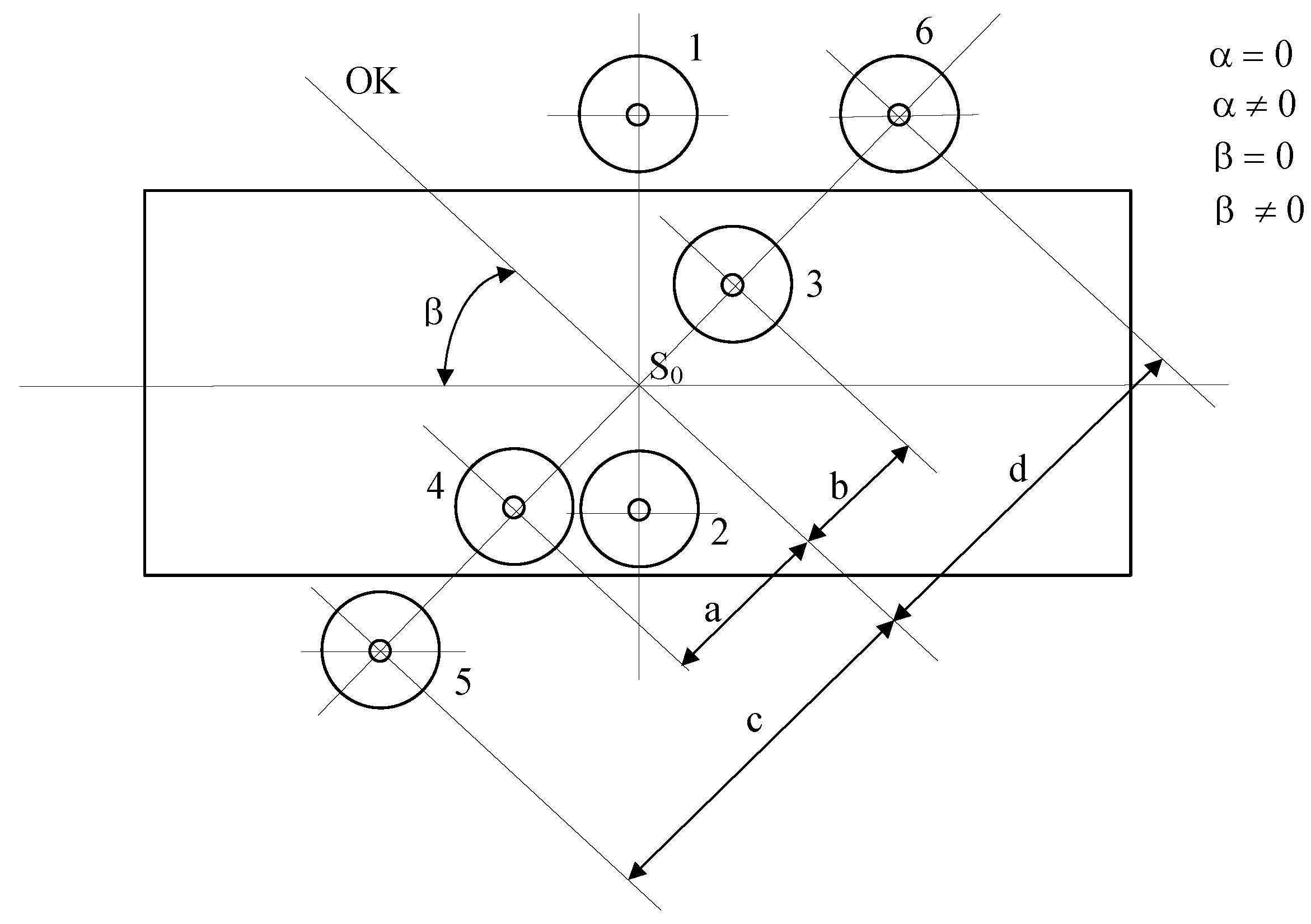
Figure 5.
Variables used during determining the equations of motion.

Figure 6.
Stimulating forces acting on the riddle.
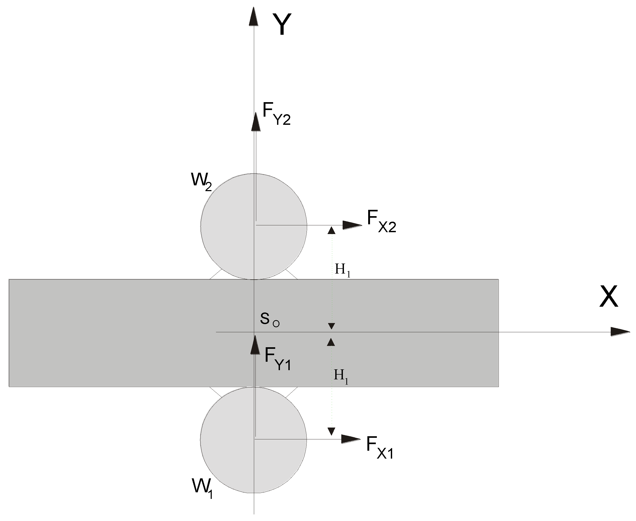
Figure 7.
The schematic representation of the test unit. 1—frame, 2—elastic screen suspension, 3—riddle with a sieve, 4, 5—vibrators, 6—movable charging hopper, 7—a container for sifted material.
Figure 7.
The schematic representation of the test unit. 1—frame, 2—elastic screen suspension, 3—riddle with a sieve, 4, 5—vibrators, 6—movable charging hopper, 7—a container for sifted material.
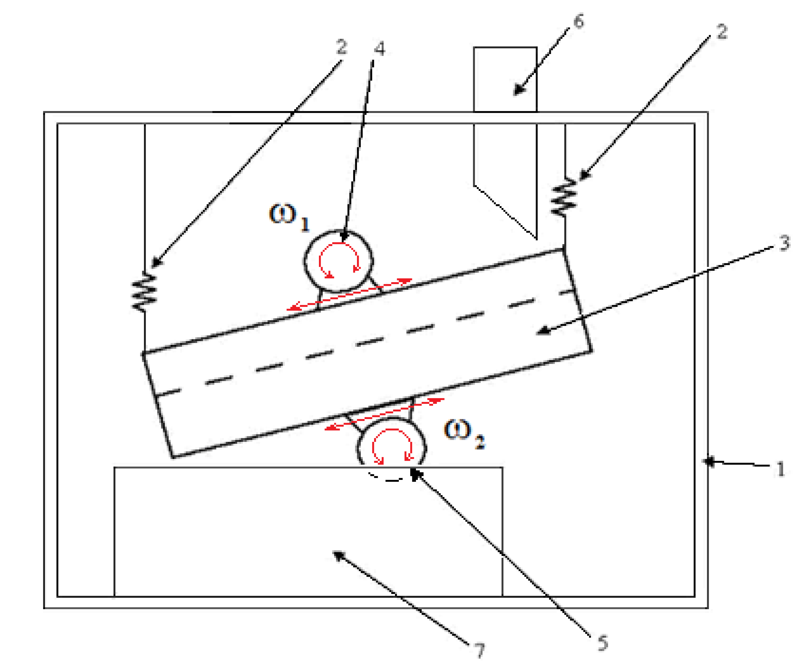
Figure 8.
The angles of trajectories of the sieve vibrations.
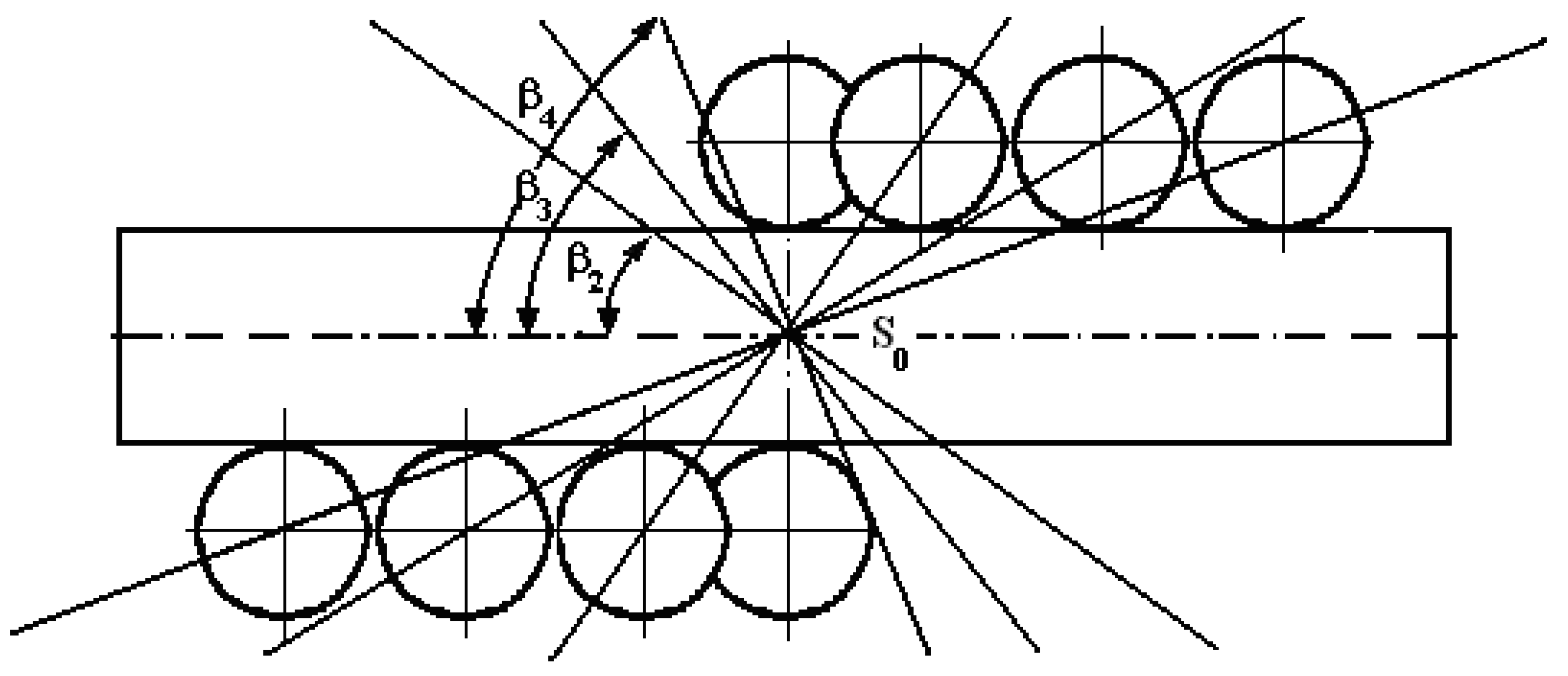
Figure 9.
Settings of unbalanced masses.
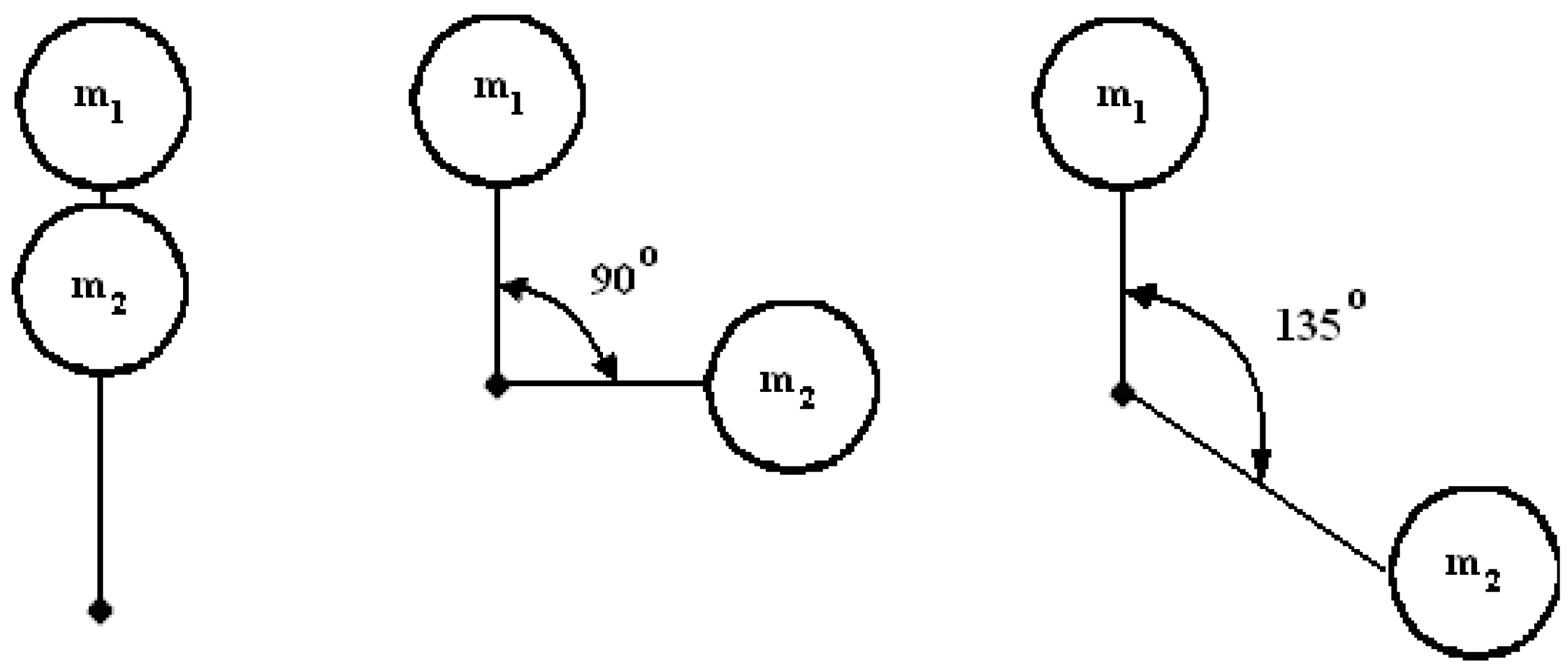
Figure 10.
The systematic presentation of the system measuring the vibration amplitudes of the analyzed sieve.
Figure 10.
The systematic presentation of the system measuring the vibration amplitudes of the analyzed sieve.
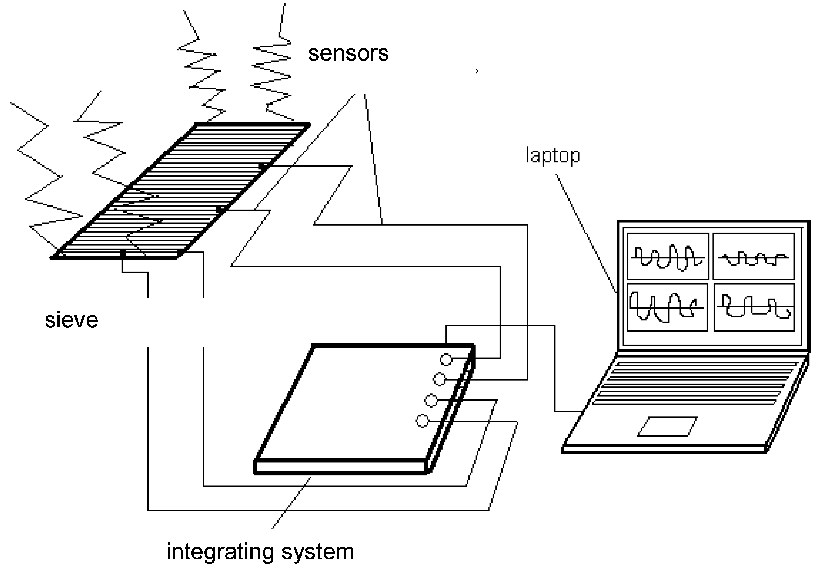
Figure 11.
The positions of the piezoelectric sensors mounted on the sieve.

Figure 12.
Traffic paths for compatible synchronization. Rotational frequency ratio of vibrators : (a) ; (b) ; (c) ; (d) .
Figure 12.
Traffic paths for compatible synchronization. Rotational frequency ratio of vibrators : (a) ; (b) ; (c) ; (d) .
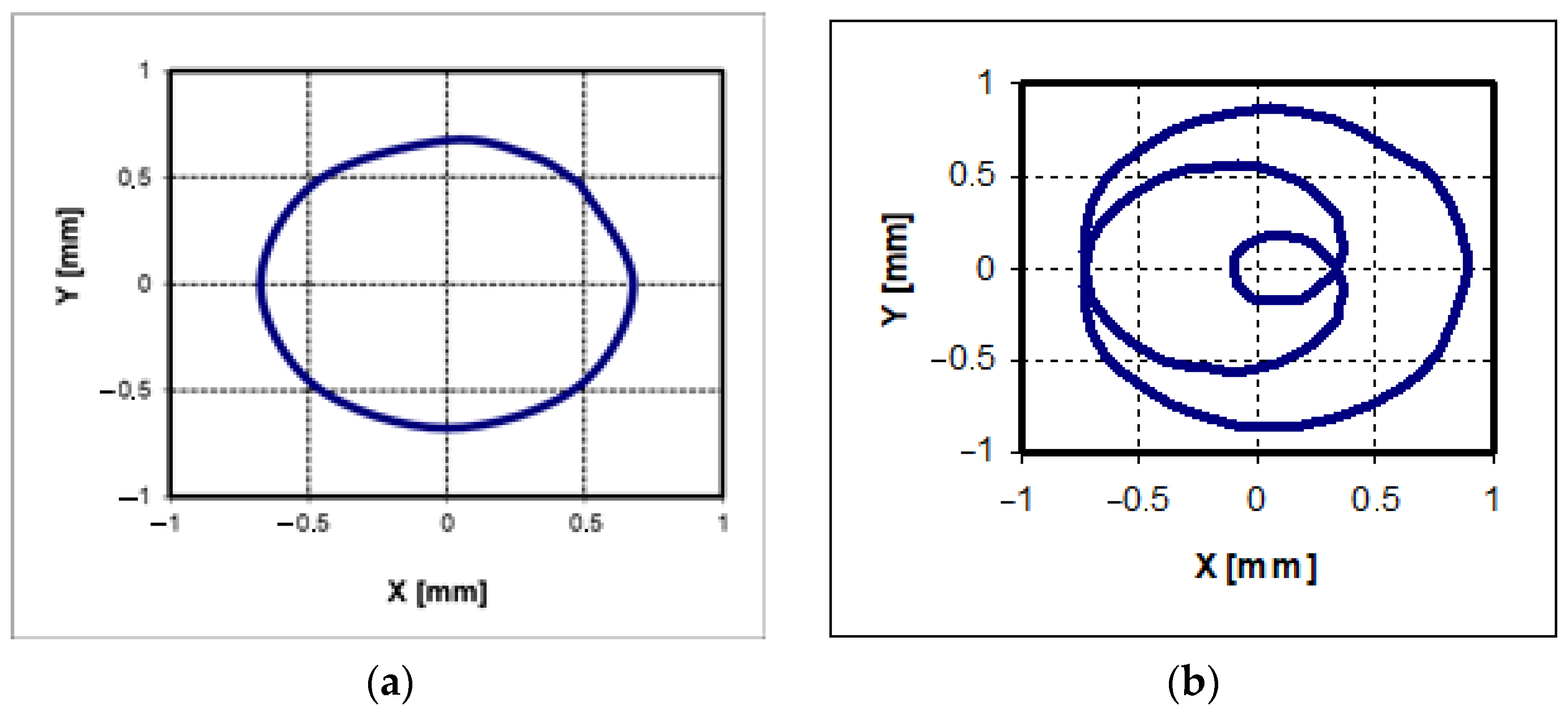

Figure 13.
Traffic paths for reverse synchronization. Rotational frequency ratio of vibrators : (a) ; (b) ; (c) ; (d) .
Figure 13.
Traffic paths for reverse synchronization. Rotational frequency ratio of vibrators : (a) ; (b) ; (c) ; (d) .
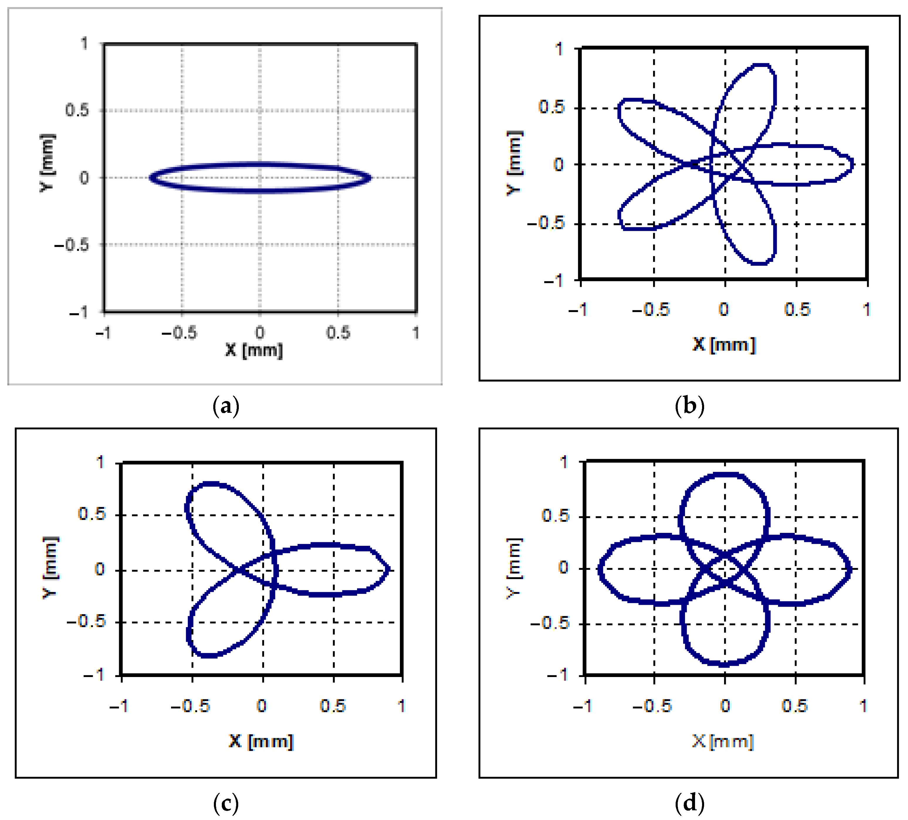
Figure 14.
Traffic paths for compatible synchronization. Rotational frequency ratio of vibrators : (a) ; (b) ; (c) ; (d) .
Figure 14.
Traffic paths for compatible synchronization. Rotational frequency ratio of vibrators : (a) ; (b) ; (c) ; (d) .

Figure 15.
Traffic paths for reverse synchronization. Rotational frequency ratio of vibrators : (a) ; (b) ; (c) ; (d) .
Figure 15.
Traffic paths for reverse synchronization. Rotational frequency ratio of vibrators : (a) ; (b) ; (c) ; (d) .

Table 1.
The values of the ratio obtained from the simulation and the measurement for the compatible and the reverse synchronization and various values of the ratio.
Table 1.
The values of the ratio obtained from the simulation and the measurement for the compatible and the reverse synchronization and various values of the ratio.
| Synchronization | Compatible | Reverse | ||
|---|---|---|---|---|
| Simulation | Measurement | Simulation | Measurement | |
| 1 | 0.081 | 0.176 | 0.175 | 0.180 |
| 2/3 | 0.155 | 0.232 | 0.101 | 0.238 |
| ½ | 0.157 | 0.229 | 0.105 | 0.226 |
| 1/3 | 0.155 | 0.253 | 0.127 | 0.259 |
Publisher’s Note: MDPI stays neutral with regard to jurisdictional claims in published maps and institutional affiliations. |
© 2022 by the authors. Licensee MDPI, Basel, Switzerland. This article is an open access article distributed under the terms and conditions of the Creative Commons Attribution (CC BY) license (https://creativecommons.org/licenses/by/4.0/).
Share and Cite
MDPI and ACS Style
Modrzewski, R.; Obraniak, A.; Rylski, A.; Siczek, K. A Study on the Dynamic Behavior of a Sieve in an Industrial Sifter. Appl. Sci. 2022, 12, 8590. https://doi.org/10.3390/app12178590
AMA Style
Modrzewski R, Obraniak A, Rylski A, Siczek K. A Study on the Dynamic Behavior of a Sieve in an Industrial Sifter. Applied Sciences. 2022; 12(17):8590. https://doi.org/10.3390/app12178590
Chicago/Turabian StyleModrzewski, Remigiusz, Andrzej Obraniak, Adam Rylski, and Krzysztof Siczek. 2022. "A Study on the Dynamic Behavior of a Sieve in an Industrial Sifter" Applied Sciences 12, no. 17: 8590. https://doi.org/10.3390/app12178590
Note that from the first issue of 2016, this journal uses article numbers instead of page numbers. See further details here.