
Implementation of a Noise-Shaped Signaling System through Software-Defined Radio


1
The CCS Graduate School of Green Transportation, Korea Advanced Institute of Science and Technology (KAIST), Daejeon 34141, Korea
2
Agency for Defense Development (ADD), Daejeon 34186, Korea
*
Author to whom correspondence should be addressed.
Appl. Sci. 2022, 12(2), 641; https://doi.org/10.3390/app12020641
Submission received: 16 November 2021
/
Revised: 6 January 2022
/
Accepted: 9 January 2022
/
Published: 10 January 2022
(This article belongs to the Special Issue Wireless Communication: Applications, Security and Reliability)
Abstract
:Along with the development of electromagnetic weapons, Electronic Warfare (EW) has been rising as the future form of war. Especially in the area of wireless communications, high security defense systems such as Low Probability of Detection (LPD), Low Probability of Interception (LPI), and Low Probability of Exploitation (LPE) communication algorithms are being studied to prevent military force loss. One LPD, LPI, and LPE communication algorithm, physical-layer security, has been discussed and studied. We propose a noise signaling system, a type of physical-layer security, which modifies conventionally modulated I/Q data into a noise-like shape. To suggest the possibility of realistic implementation, we use Software-Defined Radio (SDR). Since there are certain hardware limitations, we present the limitations, requirements, and preferences of practical implementation of the noise signaling system. The proposed system uses ring-shaped signaling, and we present a ring-shaped signaling system algorithm, SDR implementation methodology, and performance evaluations of the system using the metrics of Bit Error Rate (BER) and Probability of Modulation Identification (PMI), which we obtain by using a Convolutional Neural Network (CNN) algorithm. We conclude that the ring-shaped signaling system can perform high LPI/LPE communication functioning because an eavesdropper cannot obtain the correct modulation scheme information. However, the performance can vary with the configurations of the I/Q data-modifying factors.
1. Introduction
With the development of electromagnetic weapons, Electronic Warfare (EW) has been rising as the future form of wars [1,2]. In EW, the attackers’ purposes are to capture military secrets and cause the malfunctioning of core electronic equipment such as radios, radars, or spy satellites using Electromagnetic Pulse (EMP) and High-Power Microwave (HPM) attacks. Leakage of military secrets can directly cause a significant loss of military forces. To defend against message leakage, more complex and robust defense systems are required such as Low Probability of Detection (LPD), Low Probability of Interception (LPI), or Low Probability of Exploitation (LPE) communication algorithms [3,4,5,6]. LPD is defined as a system in which an eavesdropper cannot detect a signal at all. LPI is defined as a system in which an eavesdropper detects the presence of a signal but cannot identify the characteristics of the signal. LPE is defined as a system in which the eavesdropper detects the presence of and identifies the characteristics of a signal but cannot exploit the message. These solutions are processed at the physical-layer level. Physical-layer processing is studied to reduce complexity by hiding signals with dummy noises [7] or by using a dirty constellation algorithm. However, there is a limitation in that such systems cannot create complete noise.
Various security methods in the communication field have been proposed. Cryptography methods such as symmetrical and asymmetrical key encryption are used in wireless communication systems [8,9]. However, these methods may generate additional delays because of complex procedures due to using additional bits for security, but they are not particularly critical in the channel coding process. Physical-layer security processes have been discussed and studied to overcome these disadvantages [10,11,12,13,14]. However, still, a complex and long sequence, which can occur with additional computational overhead, is required to be used for strong security performances. Therefore, scholars are studying waveform-modifying security methods to achieve lower latency, lower complexity, and higher security [15,16].
In this paper, we propose a flexible and adaptable covert communication algorithm through a noise-shaping process in the physical layer to overcome the problems of implementation complexity and hardware dependency. The proposed algorithm focuses on modifying In-Phase and Quadrature (I/Q) forms of data. The proposed algorithm is composed of shared noise-shaping modifying factors, which are shared between the designated transmitter and receiver. After the conventional modulation process, the transmitter reshapes a noise shape using the shared noise-shaping modifying factors and the original I/Q data. The receiver or attacker, a third party, will detect the signal as a noisy signal. Since the receiver knows the shared factors, the receiver can recover the correct I/Q data while an attacker cannot.
Most previous works have concluded their studies at the simulation level while not considering real implementation. We present a practical implementation of noise signaling through SDR radios which can flexibly function with installed user-customizable software. With the implementation process, we present the realistic possibility to implement a noise-signaling system. As mentioned in [17,18], ultimate physical-layer security may be achievable when noise shaping is very similar to Additive White Gaussian Noise (AWGN). However, due to the limitations of radio hardware, it is not possible to obtain a perfect AWGN shape; certain boundaries need to be optimized to achieve both good security and recovery performance. Therefore, we decided to form the I/Q constellation data as a ring shape rather than full AWGN.
With the implemented ring-shaped signaling system SDR radios, we evaluate the system with the Bit Error Rate (BER) and Probability of Modulation Identification (PMI) performance metrics. The BER is used to calculate the differences between transmitted data bits in the transmitter and recovered data bits in the receiver. The PMI is the probability of identifying a certain modulation scheme from the attacker’s viewpoint. We obtain the PMI from the Convolutional Neural Network (CNN) algorithm, which is trained by BPSK, QPSK, 8~64 PSK, and 8~64 QAM with 0~30 dB SNR AWGN channel I/Q constellation data. From the BER, we evaluate how well noise signaling recovery can be accomplished. From the PMI, we evaluate how well the ring-shaped signaling system can hide a modulation scheme from an eavesdropper.
This paper is organized as follows. In Section 2, we provide a literature review of previous studies about covert communication techniques. A presentation of the limitations and preferences when implementing noise-shaped signaling process in real radios is found in Section 3. The proposed ring-shaped signaling system algorithm is presented in Section 4. The necessarily required functions for implementation through SDR are presented in Section 5. The performance evaluations with the BER and PMI are shown in Section 6. Lastly, the conclusion with a discussion of future work is drawn in Section 7.
2. Related Works
The importance of defending data from attackers has seen more emphasis and study recently. The authors of [3] improved system security by adding a variable cyclic prefix (CP) and frequency domain jitter. The authors of [19] proposed a random user selection method. The authors of [20] proposed precoding-aided spatial modulation to improve covert performance.
Spread spectrum technology is commonly used to improve covertness [1,21]. Spread spectrum technologies including Direct-Sequence Spread Spectrum (DSSS) and Frequency-Hopping Spread Spectrum (FHSS), and combinations of DSSS and FHSS are usually used with CDMA and Orthogonal Frequency-Division Multiplexing (OFDM) technologies for multiple access. Moreover, various studies have attempted to enhance the advantages of the spread spectrum with CDMA [5,6,22]. However, the implemented algorithms have the limitation that decoding the original message is possible when the signal is detected because of their proceedings combining a cryptographic method with spread spectrum.
To overcome this problem, physical layer security methods have been studied with wireless communication technology. The authors of [4] presented a method to improve LPI performance in the physical layer. The dirty constellations algorithm is introduced as a modulation method that adds an additional covert Quadrature Phase Shift Keying (QPSK) signal to the original modulated signal with a low information transmission rate similar to Binary Phase Shift Keying (BPSK) and QPSK. This method mimics wireless communication signals with high noise and hides the signal at a high Error Vector Magnitude (EVM) point. Therefore, the dirty constellation of the transmission signal has high covert performance. However, the constellation generated by the presented algorithm does not deviate from the form of a conventional QPSK; the attackers are likely to intercept and possibly decode the original message. The multiple modulation schemes broadcasting method enhances security performance compared with a single modulation scheme system [23]. A continuously varying modulation scheme has been proposed [24,25]. A method of shaping the symbol similar to AWGN has also been proposed [26]. However, the proposed methods have limitations in that the modulation scheme may easily be guessed and require dummy data.
In this paper, we propose a ring-shaped signaling system algorithm that cannot demodulate the message even if the transmitted signal is detected and intercepted. The algorithm mainly utilizes the LPI/LPE communication function. In this algorithm, additional shared modifying factors are used to shape and recover the signal. This method has the advantages of being easy to implement, being adaptable for any communication system using I/Q data, and effectively decreasing attackers’ probability to decode the message.
3. Noise-Shaped Signaling Definition, Limitation, and Preferences
The purpose of using noise-shaped signaling is to achieve signal transmission security. Three categories of noise-shaped signaling function are discussed: (1) the eavesdropper is not able to detect the transmitting RF signal (LPD); (2) the eavesdropper is able detect the presence of a transmitting RF signal but not able to interpret the signal characteristics (LPI); and (3) even if the eavesdropper interprets the signal, he or she is not able to exploit it due to an inability to decode the correct message (LPE). The ultimate goal of noise-shaped signaling is to transform the I/Q signal distribution to make it almost equal to a Gaussian distribution. As the signal is transformed into a form almost equal to Gaussian noise, the RF signal may achieve the highest security, achieving LPD, LPI, and LPE functionalities. However, when trying to implement the signaling methods in a real radio, the receiver may face very difficult conditions for decoding the RF signal due to several hardware limitations.
When adapting Gaussian distributed noise-shaped signaling through SDR, there are several issues to be considered, such as signal power control, signal synchronization, and additional noise mixing processes.
For signal power control issues, typical radios have a maximum transmission power limitation for several reasons, which is the same as SDR. In addition, SDR receivers control their own gain to protect from overpowered received signals or to increase the performance when the transmission power is too low. Therefore, the noise-shaped signaling process also requires following the maximum power limitation rule. Reshaped signal power should not exceed the maximum power of the original signal and therefore requires the highest bound. Lower power matters to radio performance as well. To correctly decode messages, a certain value of decision distance between I/Q data is required. When lowering the received power, the decision distances decrease as well and can harm the radio performance. Therefore, considering the possibility of the appearance of critical additional noise between the communication channels, noise-shaped signaling should have the lowest bound.
The basic concept of noise-shaped signaling is to modify the original signal into a noise-like form. The process may be performed by addition, subtraction, multiplication, or division of the original signal and modifying parameters. When the receiver recovers the original signal from the received signal, which is affected by the noise-shaped signaling and channel, the receiver requires almost perfect synchronization in both the frequency and time domains to counter the noise-shaped signaling effect and face only the channel effect. Therefore, the communication system should have a function for perfect synchronization.
While the additional noise mixing process proceeds, one of the following calculations is used: addition, subtraction, multiplication, or division. Additionally, the mixing process may directly apply to data bits and I and Q data at the same time or independently. In SDR, the transmitter and receiver gain can be set up differently, which can change the I/Q data magnitude. Therefore, addition or subtraction processes may not be feasible when implemented through SDR. In addition, synchronization functions use the inputs as I/Q data forms. Therefore, to achieve the purpose of securing modulation scheme information, application of the noise mixing process to the I/Q data after the modulation function at the transmitter and before demodulation function at the receiver is adapted.
With the observed definitions, limitations, and preferences, we propose the ring-shaped signaling system algorithm as a suitable noise-signaling algorithm for implementation through SDR. Detailed descriptions of the algorithm, implementation processes, and performance analyses are presented in the following sections.
4. Ring-Shaped Signaling System Algorithm
A block diagram of the proposed ring-shaped signaling system is shown in Figure 1. After the conventional modulation process of the communication system, a noise-shaping operation is added to modify a signal having the characteristics of a noise. The envelope that is used for the noise-shaping operation is composed of phase and magnitude, and it is possible to control the noise level using different variables. The phase envelope variable rotates the constellation. For example, in a PSK signal, the result of the rotation process is to modify the PSK constellation to a different order of PSK signal that makes it difficult for attackers to interpret the data. The signal looks like a noisier signal when the rotation order increases. The magnitude envelope displaces the original I/Q constellation data points close to the origin point (I/Q = (0,0)). The signal transformed by the magnitude envelope looks more like white noise, and the magnitude modification process lowers the power of the signal, making it difficult to intercept.
The expected modified constellation obtained through the proposed ring-shaped signaling system is shown in Figure 2. With the proposed system, the data points around the origin (I/Q = (0,0)) are displaced to a certain low boundary to form a ring. With the ring-shaped signal, the constellation seems faded or like white noise with a hole at the center. Therefore, eavesdroppers have difficulty interpreting the data because they are unable to determine the modulation scheme. In addition, since the modified signal is similar to noise, the average transmission power of the signal is relatively lower than the original signal. The lower transmission power also enables a decrease in the probability of intercepting the signal.
The ring-shaped signaling system converts a conventionally modulated signal as shown in Equation (1) into a modified signal using a magnitude-modifying factor and a phase modifying factor, as shown in Equation (2). The magnitude-modifying factor and the phase-modifying factor can adjust the noise level through independent variables. The covertness performance can be changed according to the modifying factors:
The phase-modifying factor is generated through the process shown in Figure 3. After generating random number bits bn with same length as the original data length n, the random bits are added with additional bits, which are same length as Ip. The generated random bits, which have a length of n + Ip, are grouped with Ip − 1 number of bits and then converted to a decimal number Nn, which has same length as original data length n. The converted decimal is divided by the value of the power (2) of the intensity level Ip. Through this process, the range of (0, 2π) is divided by a certain resolution according to the intensity level. The modified signal is rotated as shown in Figure 2b. Since the phase rotation process is performed with I/Q data, additional key bits are not required. Thus, the data rate for the intended receiver stays same, while the previous methods [4,26] that use additional key bits have increased data rates.
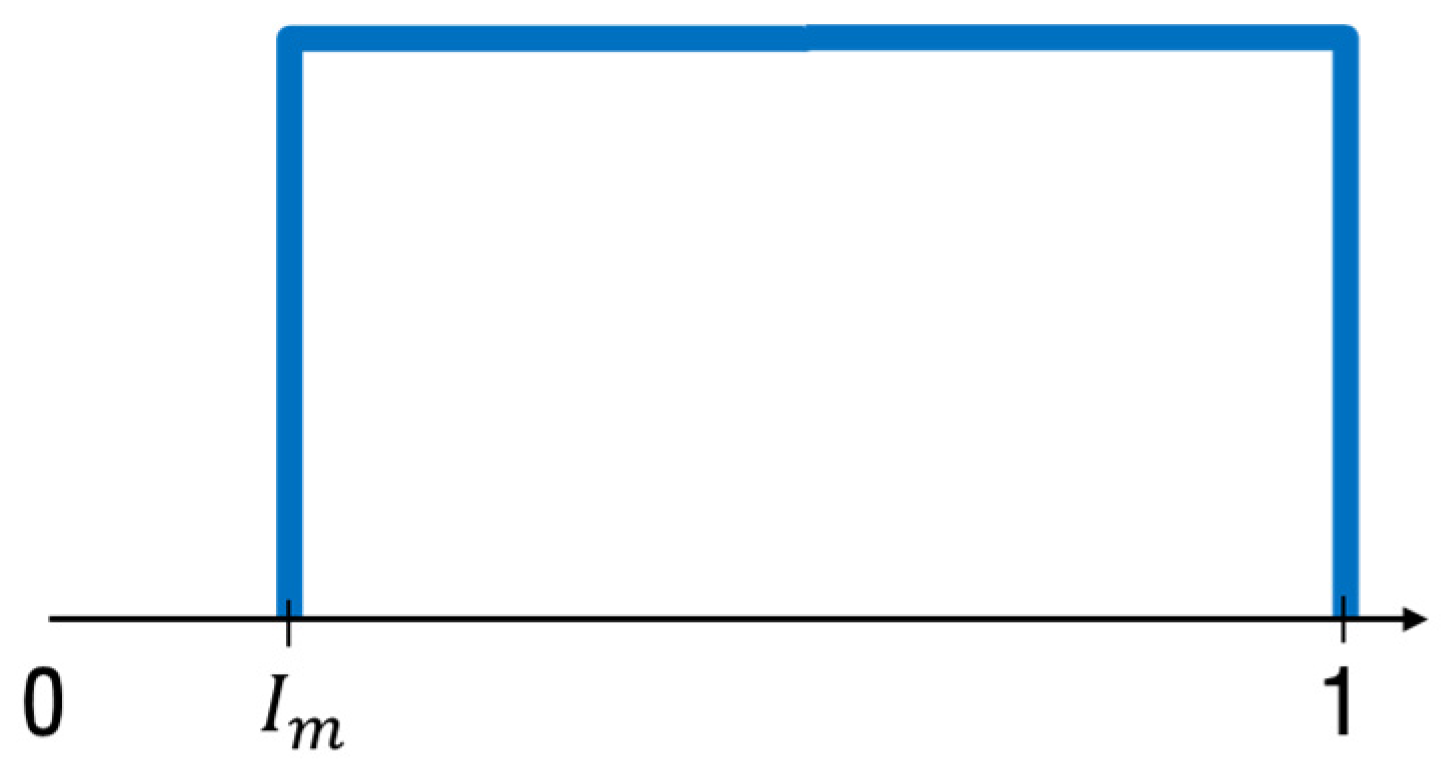
The magnitude-modifying factor is applied to the original signal by multiplying it by a uniformly distributed random number that has a length equal to that of the transmitted data. As shown in Figure 4, when generating the magnitude-modifying factor, the minimum value of the random number is adjusted according to the magnitude intensity level Im to control the lower boundary, which influences the signal magnitude.
The modified signals produced by the phase-modifying factor and magnitude-modifying factor are shown in Figure 5a,b, respectively. The signal modified by the phase-modifying factor contains data points that are evenly distributed at certain degrees of angles according to the resolution of the intensity level and in the shape of a circle, as shown in Figure 5a. The signal modified by the magnitude-modifying factor has data points that are distributed with different magnitude values. They are displaced toward the inside of the circle, as shown in Figure 5b.
The ring-shaped signaling system, simultaneously applied with the phase-modifying factor and magnitude-modifying factor, has a lower average signal energy than the original signal due to the reduced average magnitude, as shown in Equation (3). Since the modified signal has flexibly changing power as shown in Equation (3), and the signal bandwidth or data rate is not affected by the ring-shaped signaling system, the Shannon capacity limit is only affected by Im, as shown in Equation (4). The reduction in signal energy makes it possible to increase the covertness performance, but the performance of the recovered communication system is degraded because it is more sensitive to the channel noise. The reduced magnitude is directly related to reduced decision-making distance, as shown in Equation (5). Therefore, the noise signaling system must be driven by adjusting the parameters for the best performance of the recovered communication system and the best covertness at the same time:
To measure the constellation confusion degree, we use the information entropy of the constellation data (Y = a + j * b):
where , p(a,b) is the joint probability density function for a and b and Δ is the quantification accuracy. Larger information entropy means less leakage of information. The ring-shaped signaling affects p(a,b) and Δ, Ip affects p(a,b), and Im affects Δ. As Ip increases, p(a,b) decreases. For example, if the original system has QPSK, p(a,b) = 1/4 is modified to an 8 PSK and 16 PSK shape, and p(a,b) changes to 1/8 and 1/16, respectively. In addition, as Im decreases, the average power decreases as shown in Equation (3). The lowered power is directly related to a lower Δ, which also affects Γ(i,j). With the combinations of Im and Ip values, the information entropy will increase with the minimum value, as with the original system’s information entropy.
5. Functions Required for SDR Implementation
We implemented the ring-shaped signaling system through SDR. Due to several configurational complexities, we focused only on the PSK transmitting and receiving communication system, evaluating whether an effectively covert QPSK system could be implemented without performance degradation. We used Ettus USRP B210 for SDR and Matlab for the software.
When the ring-shaped signaling system is implemented through SDR, there are several important functions. Because the conventional QPSK signal shape changes to a signal with a different modulation order due to the phase-modifying factor, any frequency-related functions are required among the transceiver.
For data recovery, accurately extracting the envelope is necessary. To accurately eliminate the envelope values for each piece of data, accurate synchronization between the transmitted and received data is needed to align the data in the correct order. For accurate synchronization, pre-processes with an RF signal, performed using certain information such as the modulation, the sample rate of the transmitted signal, or the data header are required.
Within the RF signal pre-processing, we considered the required functions that were affected according to the modulation scheme types, which were the carrier synchronizer function and frequency offset estimator function. The carrier synchronizer function uses the Phase-Locked Loop (PLL) method, Direct Digital Synthesizer (DDS), and a phase error detector. Through the phase error calculation [27,28], which depends on the modulation schemes, the calculated phase error sends through DDS and uses phase shifting to correct for the frequency offset. The frequency offset estimator function uses a frequency offset estimator which estimates the frequency offset by the auto-correlation and frequency offset corrector, which corrects the frequency based on the estimated offset value [29]. Since the PLL method depends on a different step of the phase error value, the transceiver must share the phase information of the same MPSK modulation order to correctly estimate the phase error step. In the case of using the ring-shaped signaling system, the received RF signal is changed to a certain order of MPSK, which is varied by the phase-modifying factor. Since the order can be flexibly changed by the phase modifying factor, the PLL setting of the receiver must match with the order of MPSK. For the same reason, the frequency offset estimator function must also be adjusted to the changed PSK order. The carrier synchronizer function and frequency offset estimator function are shown in Figure 6a,b below.
In a conventional communication system, the symbol length depends on the type of modulation scheme and is calculated as shown in Figure 7, dividing the bit length by log2 of the modulation scheme. This calculation process is also applied to the header, data, and tail bits. The converted symbol is used to form RF signals in the transceivers. In the conventional communication system, the symbol form of the header uses the input for the carrier synchronizer and frequency offset estimator functions.
In general, if the length of the header changes, it is difficult to find the exact starting point of the data, and so accurate alignment is not possible. Therefore, we propose a symbol generation process that generates symbol forms of the data and header independently as shown in Figure 8. The process first uses a conventional symbol data transformation process only for the data bit part, generating predefined header symbols and then merging the two-part symbol data to generate a full form of symbol data. For accurate synchronization, symbols 180° apart were chosen as the symbol form of the header. The separately generated symbol form header could have the same length no matter what phase modifying factor was used. With the same shared header, accurate data alignment for synchronization can be obtained even if the PSK modulation order is changed over a flexibly changing phase of the ring-shaped signal.
6. Results
6.1. Simulation Results
For evaluating the ring-shaped signaling algorithm for a conventional communication system, Matlab simulations with varying Im values were performed with a fixed value of Ip, since Ip was not effective for the intended receivers. The simulations were performed with conventional QPSK, 16 QAM, and 64 QAM systems under an AWGN channel. The simulations were performed without any additional error correction coding or performance-improving functions. As shown in Figure 9, the ring-shaped signaling algorithm properly reshaped the constellations of QPSK, 16 QAM, and 64 QAM. Moreover, since Im multiplied the magnitude, the reshaped constellation had a more complex shape for QAM than PSK, and the complexity increased with a higher modulation order. However, as shown in Figure 10, interestingly, the effect of Im variation toward the BER was similar no matter what modulation scheme was used. The following sections present the implementation of the ring-shaped signaling algorithm with SDR. Due to several configuration complexities, we only focused on implementation with the PSK system, and we considered the implementations with a QAM system for future work.
6.2. SDR Performance Evaluations
The environmental set-up of the SDR transceiver experiment is shown in Figure 11. It consisted of a transmitter, a laptop that controlled the SDR transmitter, a receiver, and a laptop that controlled the SDR receiver. The laptop used an Intel Core i7-8750H processer and 16 GB RAM. The utilized SDRs were Ettus USRP B210. In addition, to minimize the external noise effect, we connected the RF port via a cable during the performance evaluation experiments. The details of the SDR configuration set-up are shown in Table 1.
We conducted an experiment to compare the theoretical BER and SDR performances for QPSK, 8 PSK, and 16 PSK, which represent up to four different levels of phase-modifying factor. As shown in Figure 12, we confirmed that the trends for theoretical and SDR performance were somewhat similar. However, as the modulation order increased, we observed that the differences between the SDR performance and theory increased. Additionally, at low SNR values (approximately less than 3 dB), SDR performance had more error than the theory. However, as the SNR increased, we observed the SDR performance having similar trends to the theoretical performance. When comparing the lower SNR region performances, the differences between the SDR and theoretical performance decreased, and the trends were somewhat similar. Therefore, we may expect the SDR performance at a higher SNR region to be similar to that of the theory, especially for the lower modulation scheme, with an adjustment of few dBs.
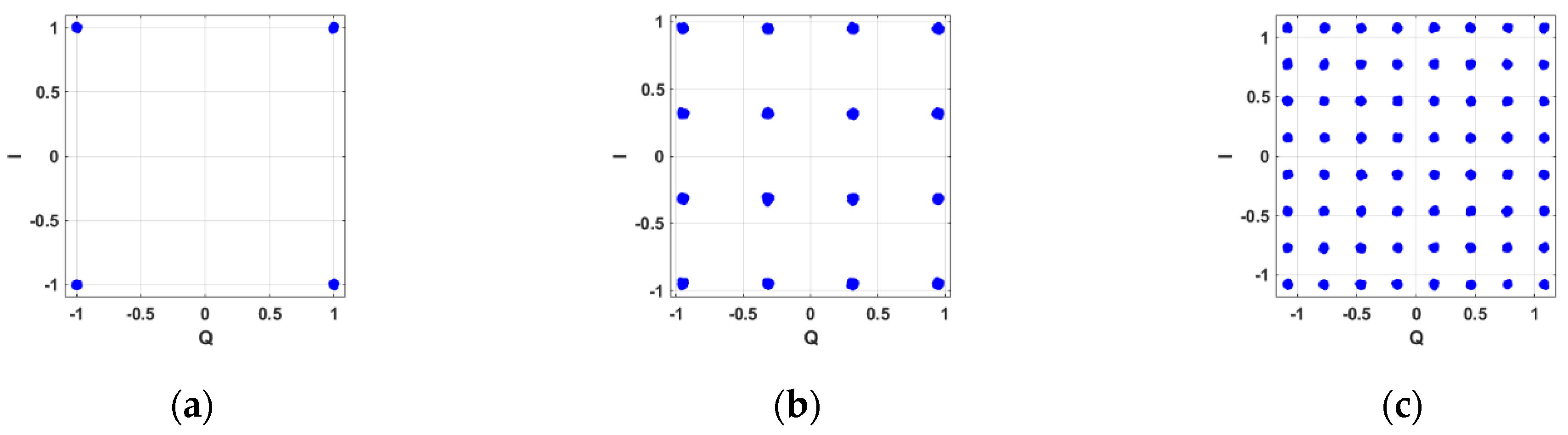
Even though there were some differences observed for the BER performance, the ring-shaped signaling system placed a higher priority on the I/Q constellation shape than on recovered communication performance. As shown in Figure 13, we confirmed that the I/Q constellation forms of QPSK, 8 PSK, and 16 PSK were clearly distinguishable. From this observation, we could define that the SDR system’s recovering data function was not perfectly working, even though the I/Q constellation shaping was working properly. As we observed in the BER performance evaluation, the error between the theoretical value and SDR performance according to the modulation order increased, and the I/Q constellation data points’ concentrations were more scattered as the modulation order increased. With the confirmed I/Q constellation working properly up to 16 PSK, the ring-shaped signaling system implementation through SDR could function up to Ip = 4.
To evaluate whether the ring-shaped signaling system was functioning properly, we conducted transceiver performance evaluation experiments by varying the phase- and magnitude-modifying factors. As shown in Figure 14a, the performance degraded as the magnitude-modifying factor decreased. As shown in Figure 14b, the performance could be recovered even though different phase-modifying factors were applied. As shown in Figure 14b, in the case of Ip = 4 for 16 PSK, full recovery was not achieved due to the existence of functional error for the 16 PSK modulation scheme performance in SDR without noise signaling. Therefore, we assumed that if the plain SDR transceiver was properly functioning, perfect performance recovery with different phase-modifying factors could possibly be achieved. Moreover, the eavesdropper could not recover the original data bits no matter the SNR, Im, or Ip values, while the Symbol Error Rate (SER) decreased with a higher SNR with the proposed method in [25].
6.3. PMI Performance Evaluations
To define the covertness performance, we conducted modulation identification evaluations with the CNN-based modulation identification algorithm. The purpose of the evaluation was to check whether a third party could identify what modulation scheme was being used. The CNN algorithm was constructed and trained with BPSK, QPSK, 8 PSK, 16 PSK, 32 PSK, 64 PSK, 8 QAM, 16 QAM, 32 QAM, and 64 QAM modulation scheme data with a 0~30-dB SNR channel and using Matlab. With the trained CNN algorithm, we could obtain PMI as a performance metric. PMI is an indicator showing the probability of recognizing the modulation scheme, where a higher value indicates a higher probability to be recognized.
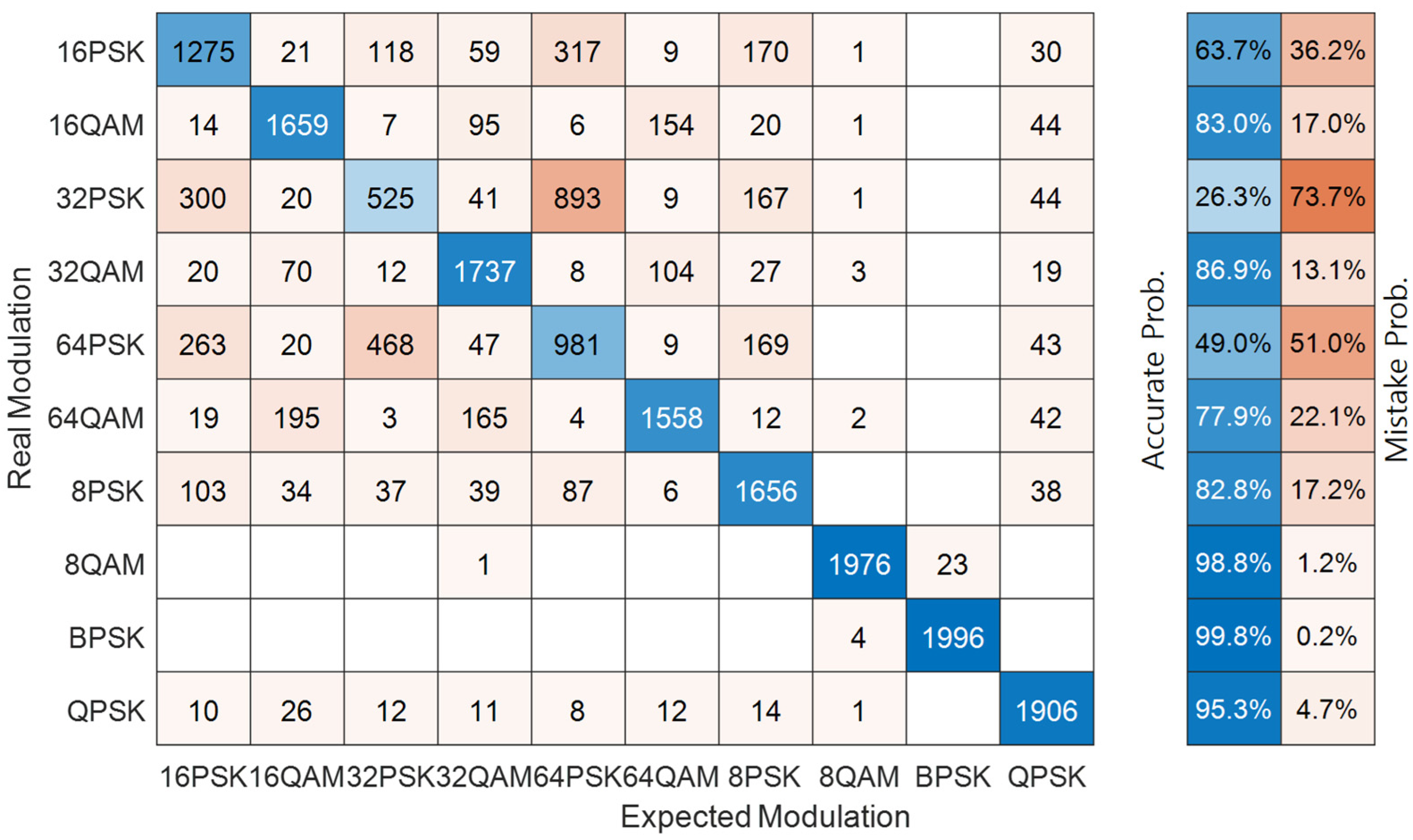
From the modulation identification accuracy experiment, we evaluated the prediction accuracy of the CNN algorithm for trained modulations. We generated 20,000 signal data per each modulation scheme, and each instance of signal data had 100,000 data symbols. The CNN algorithm was trained with 10 different modulation schemes. Within 20,000 signal sets, 80% of them were used for training, 10% for validation, and 10% for testing, while 2000 signal data were used to evaluate the CNN algorithm performance. As shown in Figure 15, in the case of QAMs, the probabilities were at least 80%, even for the higher modulation orders. However, in the case of PSKs, the probabilities were significantly lowered for the modulation order of 32 or higher. Therefore, the modulation order of up to 16 PSK for PSK and any QAM could be accurately detected. Therefore, the PMI obtained from the CNN was trustable.
Using the developed CNN algorithm, we evaluated which modulation was recognized from the eavesdropper point of view when the ring-shaped signaling system was applied to a conventional QPSK system. For this, we varied the magnitude- and phase-modifying factors. Both factors of the ring-shaped signaling system, the change in magnitude and phase, were fixed.
We conducted an experiment of Ip = 1 with a varying magnitude-modifying factor. As shown in Figure 16, the CNN algorithm properly detected the modulation scheme as QPSK for a high magnitude-modifying factor. However, as the magnitude-modifying factor decreased, the CNN algorithm recognized the system as 64 QAM and further confused which modulation scheme was used. From this experiment, we observed that the modulation scheme could be effectively hidden when Im was less than about 0.3. Additionally, we could conclude that the ring-shaped signaling system had LPI communication functionality due to the ability to hide the modulation scheme from the eavesdropper.
We conduct another similar experiment but with Ip = 4. As shown in Figure 17, the CNN algorithm could not be used to infer QPSK for any scenario. Moreover, when the magnitude-modifying factor was decreased, the algorithm was recognized as QAM signals. In addition, even when the magnitude increased, the algorithm recognized the signals as 16 PSK rather than QPSK signals, the original modulation scheme. Therefore, we confirmed that the modulation scheme could not be inferred when the ring-shaped signaling system was applied, achieving LPE communication functionality. Furthermore, we are sure that if the phase modifying factor was large enough to scatter the I/Q constellation points as white noise, modulation scheme leakage would not occur even for the high magnitude-modifying factor, and it would be possible to achieve both LPI and LPE communication functionality at the same time.
7. Conclusions
As EW attacks have become more varied with the development of modern technologies, a proper defense system for a specific type of attack or a robust defense system is required. In wireless communication systems, the attackers’ purposes are to detect the presence of communication, intercept signal characteristics, decode messages that contain military secrets, and disable the communication system. To counter such moves, several covert communication techniques are used to defend against various attacks. In addition, physical-layer defense techniques are studied to achieve LPD, LPI, and LPE communication functionalities.
In this paper, we proposed the ring-shaped signaling system, which is flexibly adaptable, easily implementable, and improves security in response to LPI and LPE communication functions. The proposed ring-shaped signaling system modifies the generated I/Q signal into a ring shape via shared magnitude- and phase-modifying factors. In addition, the performance modification of the proposed system was formulated and simulated from the perspective of the BER and transmission power. Furthermore, we implemented a noise signaling system through SDR and presented the limitations, requirements, and preferences of configurations of noise signaling when implemented through SDR. Performance evaluation of noise signaling system-installed SDRs was performed with the performance metrics of the BER and PMI.
From the evaluations, we observed that the recovered BER performance was affected by the values of the magnitude-modifying factors but not affected by the phase-modifying factor. Additionally, the effect of the magnitude-modifying factor was similar for any modulation schemes. With the reduction of the magnitude-modifying factor, the recovered BER performance became worse. However, PMI increased with the reduced magnitude-modifying factor value. At the same time, the eavesdropper could not identify the correct modulation scheme due to the effect of the phase-modifying factor. However, the eavesdropper may have recognized some modulation scheme information that might be used to predict the original modulation scheme. From these observations, we could conclude that combinations of using the magnitude- and phase-modifying factors with proper configuration values could achieve strong LPI and LPE security performance and good recovery performance at the same time.
For future work, the following studies can advance noise signaling research. We tested and validated the noise signaling algorithm with only the M-PSK system. Therefore, the same comparison and validation processes with the M-QAM system are needed. Using channel states to extract pre-shared modifying factors can solve the limitation of our requirement that the transmitter and receiver must share modifying factors. We only considered one-to-one communication networks. However, since the usual communication networks use multiple radios, we need to consider Media Access Control (MAC) as well as upper layer processes. Even though we have presented practical implementation through SDR, this is still a basic presentation. Therefore, further implementation with commercialized products and further experiments in real environments will be needed.
Author Contributions
All the authors have contributed to collecting results, performing analysis, and creating this article. All authors have read and agreed to the published version of the manuscript.
Funding
The authors gratefully acknowledge the support from the Electronic Warfare Research Center at the Gwangju Institute of Science and Technology (GIST), originally funded by the Defense Acquisition Program Administration (DAPA) and the Agency for Defense Development (ADD).
Conflicts of Interest
The authors declare no conflict of interest. The funders had no role in the design of the study; in the collection, analyses, or interpretation of data; in the writing of the manuscript, or in the decision to publish the results.
References
- Bash, B.A.; Goeckel, D.; Towsley, D.; Guha, S. Hiding information in noise: Fundamental limits of covert wireless communication. IEEE Comm. Mag. 2015, 53, 26–31. [Google Scholar] [CrossRef] [Green Version]
- Spezio, A.E. Electronic warfare systems. IEEE Trans. Microw. Theory Technol. 2002, 50, 633–644. [Google Scholar] [CrossRef]
- Bouanen, M.; Gagnon, F.; Kaddoum, G.; Couillard, D.; Thibeault, C. An LPI design for secure ofdm systems. In Proceedings of the MILCOM 2012—2012 IEEE Military Communications Conference, Orlando, FL, USA, 29 October–1 November 2012; pp. 1–6. [Google Scholar]
- Dutta, A.; Saha, D.; Grunwald, D.; Sicker, D. Secret agent radio: Covert communication through dirty constellations. Int. Workshop Inf. Hiding 2012, 7692, 160–175. [Google Scholar]
- Gupta, R.; Anuradha, S. A direct sequence spread spectrum transceiver with enhanced security using chaotic and gold sequence. In Proceedings of the 2018 9th International Conference on Computing, Communication and Networking Technologies (ICCCNT), Bengaluru, India, 10–12 July 2018; pp. 1–6. [Google Scholar]
- Ksheerasagar, T.K.; Anuradha, S.; Avadhootha, G.; Charan, K.S.R.; Rao, P.S.H. Performance analysis of ds-cdma using different chaotic sequences. In Proceedings of the 2016 International Conference on Wireless Communications, Signal Processing and Networking, Chennai, India, 23–25 March 2016; pp. 2421–2425. [Google Scholar]
- Prasad, R.; Ojanpera, T. An overview of cdma evolution toward wideband cdma. IEEE Commun. Surv. 1998, 1, 2–29. [Google Scholar] [CrossRef]
- Hasrouny, H.; Samhat, A.E.; Bassil, C.; Laouiti, A. VANet security challenges and solutions: A survey. Veh. Commun. 2017, 7, 7–20. [Google Scholar] [CrossRef]
- Lu, Z.; Qu, G.; Liu, Z. A survey on recent advances in vehicular network security, trust, and privacy. IEEE Trans. Intell. Transp. Syst. 2019, 20, 760–776. [Google Scholar] [CrossRef]
- ElHalawany, B.M.; El-Banna, A.A.A.; Wu, K. Physical-layer security and privacy for vehicle-to-everything. IEEE Commun. Mag. 2019, 57, 84–90. [Google Scholar] [CrossRef]
- Shiu, Y.-S.; Chang, S.; Wu, H.-C.; Huang, S.; Chen, H.-H. Physical layer security in wireless networks: A tutorial. IEEE Wirel. Commun. 2011, 18, 66–74. [Google Scholar] [CrossRef]
- Torrieri, D. Principles of Spread-Spectrum Communication Systems, 3rd ed.; Springer: Cham, Switzerland, 2015. [Google Scholar]
- Wyner, A.D. The wire-tap channel. Bell Syst. Technol. J. 1975, 54, 1355–1387. [Google Scholar] [CrossRef]
- Liu, Y.; Chen, H.-H.; Wang, L. Physical layer security for next generation wireless networks: Theories, technologies, and challenges. IEEE Commun. Surv. Tuts. 2017, 19, 347–376. [Google Scholar] [CrossRef]
- Li, W.; Mclernon, D.; Wong, K.-K.; Wang, S.; Lei, J.; Zaidi, S.A.R. Asymmetric physical layer encryption for wireless communications. IEEE Access 2019, 7, 46959–46967. [Google Scholar] [CrossRef]
- Xu, Z.; Jin, W.; Zhou, K.; Hua, J. A covert digital communication system using skewed a-stable distributions for internet of things. IEEE Access 2020, 8, 113131–113141. [Google Scholar] [CrossRef]
- Park, D.; Ahn, J.; Choe, C.; Woo, S.; Ahn, S.; Choi, J. A noise-shaped signaling method for vehicle-to-everything security. IEEE Access 2021, 9, 75385–75397. [Google Scholar] [CrossRef]
- Choi, J.; Ahn, J.; Choe, C.; Shin, Y.; Park, D.; Ahn, S. Practical LPI communication with noise-shaped signaling. In Proceedings of the 2019 International Conference on Information and Communication Technology Convergence (ICTC), Jeju, Korea, 16–18 October 2019; pp. 332–337. [Google Scholar]
- Wu, B.; Zhao, J.; Luo, W. Random user selection method for lpi in multiuser miso-ofdma system. In Proceedings of the 2012 IEEE 14th International Conference on Communication Technology, Chengdu, China, 9–11 November 2012; pp. 78–81. [Google Scholar]
- Wu, F.; Dong, C.; Yang, L.-L.; Wang, W. Secure wireless transmission based on precoding-aided spatial modulation. In Proceedings of the 2015 IEEE Global Communications Conference (GLOBECOM), San Diego, CA, USA, 6–10 December 2015; pp. 1–6. [Google Scholar]
- Simon, M.; Omura, J.; Scholtz, R.; Levitt, B. Spread Spectrum Communications Handbook; Citeseer: New York, NY, USA, 1994; Volume 2. [Google Scholar]
- Popper, C.; Strasser, M.; Capkun, S. Anti-jamming broadcast communication using uncoordinated spread spectrum techniques. IEEE J. Sel. Areas Commun. 2010, 28, 703–715. [Google Scholar] [CrossRef]
- Husain, M.I.; Mahant, S.; Sridhar, R. CD-PHY: Physical layer security in wireless networks through constellation diversity. In Proceedings of the MILCOM 2012–2012 IEEE Military Communications Conference, Orlando, FL, USA, 29 October–1 November 2012; pp. 1–9. [Google Scholar]
- Pechetti, S.V.; Jindal, A.; Bose, R. Exploiting mapping diversity for enhancing security at physical layer in the Internet of Things. IEEE Internet Things J. 2019, 6, 532–544. [Google Scholar] [CrossRef]
- Althunibat, S.; Sucasas, V.; Rodriguez, J. A physical-layer security scheme by phase-based adaptive modulation. IEEE Trans. Veh. Technol. 2017, 66, 9931–9942. [Google Scholar] [CrossRef]
- Cao, P.; Liu, W.; Liu, G.; Ji, X.; Zhai, J.; Dai, Y. A wireless covert channel based on constellation shaping modulation. Secur. Commun. Netw. 2018, 1–15. [Google Scholar] [CrossRef] [Green Version]
- Rice, M. Digital Communications: A Discrete-Time Approach; Prentice Hall: Upper Saddle River, NJ, USA, 2009; pp. 359–393. [Google Scholar]
- Ming, Z.; Kuang, W. 8 PSK demodulation for new generation DVB-S2. In Proceedings of the 2004 International Conference on Communications, Circuits and Systems (IEEE Cat. No.04EX914), Chengdu, China, 27–29 June 2004; pp. 1447–1450. [Google Scholar]
- Luise, M.; Reggiannini, R. Carrier frequency recovery in all-digital modems for burst-mode transmissions. IEEE Trans. Commun. 1995, 43, 1169–1178. [Google Scholar] [CrossRef]
Figure 1.
Ring-shaped signaling system block diagram.

Figure 2.
I/Q constellation (a) before signaling process and (b) after ring-shaped signaling process.
Figure 2.
I/Q constellation (a) before signaling process and (b) after ring-shaped signaling process.

Figure 3.
Phase-modifying factor generation process.

Figure 4.
Distribution of magnitude-modifying factor.

Figure 5.
Ring-shaped signaling processed I/Q constellation (a) only affected by phase-modifying factor and (b) only affected by magnitude-modifying factor.
Figure 5.
Ring-shaped signaling processed I/Q constellation (a) only affected by phase-modifying factor and (b) only affected by magnitude-modifying factor.

Figure 6.
Block diagram of (a) carrier synchronizer function and (b) frequency offset estimator function.
Figure 6.
Block diagram of (a) carrier synchronizer function and (b) frequency offset estimator function.

Figure 7.
Transformation process of conventional bits to symbols.

Figure 8.
Proposed header and data separated symbol transformation process.

Figure 9.
Constellation of (a) QPSK original, (b) 16 QAM original, (c) 64 QAM original, (d) reshaped QPSK, (e) reshaped 16 QAM, and (f) reshaped 64 QAM.
Figure 9.
Constellation of (a) QPSK original, (b) 16 QAM original, (c) 64 QAM original, (d) reshaped QPSK, (e) reshaped 16 QAM, and (f) reshaped 64 QAM.


Figure 10.
BER simulation results (fixed Ip and varying Im) for (a) QPSK, (b) 16QAM, and (c) 64QAM.

Figure 11.
SDR performance evaluation experiment set-up.

Figure 12.
BER comparison between theoretical values and SDR performance.

Figure 13.
I/Q constellation shapes of (a) QPSK, (b) 8 PSK, and (c) 16 PSK.

Figure 14.
Performance evaluations with varying (a) magnitude-modifying factors (Im) and (b) phase-modifying factors (Ip).
Figure 14.
Performance evaluations with varying (a) magnitude-modifying factors (Im) and (b) phase-modifying factors (Ip).

Figure 15.
PMI accuracy table of constructed CNN algorithm.

Figure 16.
PMI evaluation with varying Im and Ip = 1.

Figure 17.
PMI evaluation with varying Im and Ip = 4.


Table 1.
SDR configuration parameters.
| Parameter Name | Parameter Values |
|---|---|
| Center frequency | 915 MHz |
| Bandwidth | 1 MHz |
| Data bit | 10,000 |
| Clock rate | 20 MHz |
| Header symbol length | 12 symbols |
| Message | hello world ### |
Publisher’s Note: MDPI stays neutral with regard to jurisdictional claims in published maps and institutional affiliations. |
© 2022 by the authors. Licensee MDPI, Basel, Switzerland. This article is an open access article distributed under the terms and conditions of the Creative Commons Attribution (CC BY) license (https://creativecommons.org/licenses/by/4.0/).
Share and Cite
MDPI and ACS Style
Choi, J.; Park, D.; Kim, S.; Ahn, S. Implementation of a Noise-Shaped Signaling System through Software-Defined Radio. Appl. Sci. 2022, 12, 641. https://doi.org/10.3390/app12020641
AMA Style
Choi J, Park D, Kim S, Ahn S. Implementation of a Noise-Shaped Signaling System through Software-Defined Radio. Applied Sciences. 2022; 12(2):641. https://doi.org/10.3390/app12020641
Chicago/Turabian StyleChoi, Junsung, Dongryul Park, Suil Kim, and Seungyoung Ahn. 2022. "Implementation of a Noise-Shaped Signaling System through Software-Defined Radio" Applied Sciences 12, no. 2: 641. https://doi.org/10.3390/app12020641
Note that from the first issue of 2016, this journal uses article numbers instead of page numbers. See further details here.