1. Introduction
Robotic hands, attached to multi-degrees of freedom (DOF) manipulators are considered useful for performing complex tasks in different environments, such as in nuclear power plants, space, and the seabed. In addition, an increasing application of robotic hand manipulation in everyday life is human-assisted technology.
Considering its adaptability, human intelligence can be more reliable than computers in making decisions and controlling unstructured environments. Therefore, for such situations, the application of human-assisted robots is increasing. Tele-operated robots can be useful, especially when there exist some uncertainties and unkown variables. Examples of common human–machine interfaces, such as joysticks, watch faces, and robotic replicas are presented in [
1,
2,
3].
This could be used in dangerous assembly line operations, bomb disposal robots, or possibly in surgical medicine. However data gloves can serve other applications, e.g., for sign language interpretation, it provides input to translation systems or virtual or augmented reality environments.
The present article is divided in six sections regarding the sensorial glove prototype. The first is dedicated to the introduction, while the second and third are focused on the literature review and theoretical concepts, respectively.
Section 4 mentions the results of the prototype, namely the software, while
Section 5 describes the real built prototype. Finally,
Section 6 presents the conclusion and ideas for future developments.
2. Literature Review
Human motion tracking (HMT) systems can be divided into two categories: computer-vision-based (CV) and wearable-sensor-based (WS) [
4]. The advantages of CV-based techniques stem from the use of network-depth cameras to monitor human activity and have been applied to real-world applications such as filming and security surveillance [
4]. Tech companies are also working on research and development of professional human motion tracking systems, namely Vicon and Optotrak. They work with high precision in controlled scenes but are highly dependent on the environment and its conditions, such as lighting and shooting angles. The nature of this method makes it only suitable for small and controllable cases [
4].
CV-based solutions are used in teleoperation systems. It is fairly easy for visual systems to capture contours of the human in the majority of environments, but the captured images cannot provide enough information for tracking hands in three-dimensional space. It is because the derivation of the spatial position information can lead to multiple 2D-3D mapping solutions [
5]. Furthermore, with a single source of capturing images, it is possible that some fingers are occluded and result in a non-observable problem, leading to faulty or undefined calculation of the pose [
5]. Nonetheless, it can be integrated in a multi-sensory system to complement other’s sensors weaknesses, such as the inertial measurement unit (IMU) drift problem.
WS-based HMT systems, on the other hand, do not need to deploy devices in scenarios and do not rely as much on environment factors. These type of systems tend to be more reliable and accurate. Therefore, they can be more suitable for large-scale and dynamic applications. However, these systems also tend to be pricey and use specialized equipment.
Another popular way is developed by the data glove. This method adopts technologies, such as inertial sensors, contacting electromagnetic tracking sensors, and glove instruments with angle sensors, to track the operator’s hand or arm motion which completes the required task. Until now, different types of data gloves have been developed over time, both commercial and prototype ones. Some of the commercial examples: 5th Glove, the Cyber Glove, the HumanGlove, the P5Glove, and the ShapeHand [
5].
As for the technology available right now, there are a lot of implementations and concepts of WS-based data gloves but there is no accepted standard for production. In addition, teleoperation systems still have limitations and room for improvement, especially in high precision tasks. Solutions developed for virtual reality (VR) applications are the most known but tend to be noisy because of the range of movement the application requires. Gloves developed for sign language interpretation do not need to be as accurate and are more focused on the interpretation of the pose estimation. So, there is a need for an accurate enough solution to make teleoperation of a hand manipulator desirable, and at its best as capable as a real human hand. There is a need for teleoperation in applications where it is dangerous for a human to manipulate, but the accuracy and dexterity of a human hand is needed. It can also replace some single-purpose teleoperation interfaces, such as joysticks and buttons, because of its general and intuitive nature of using a hand.
At the moment, IMUs are the main approach to WS-based HMT systems, such as gyroscopes and accelerometers. Several solutions are presented by other authors, such as in the articles [
6,
7]. The basic principle is to measure the triaxial angular velocity and acceleration of the motion by these sensors and obtain the orientation through integral operations. However, inertial sensors are known for the inevitable errors that accumulate over time [
8,
9]. The drift error is the biggest challenge faced by IMU-based HMT systems [
10,
11]. To improve HMT accuracy, the most common methods to tackle the drift error problem are as follows:
The hardware aspect using high precision sensors to minimize the drift error, such as XSens and Invensense tracking units;
The algorithm aspect enhances the system by using multi-sensor data fusion.
The availability and advancements of Micro Electrical Mechanical Systems (MEMS) technology enables the inertial sensors integrated into single chips.The company has made inertial sensors so small and low-power that they have already become a common practice in ambulatory motion analysis. For the time being, the magnetic sensors are used together with inertial sensors for accurate and drift-free orientation estimation [
12,
13,
14]. IMMU has been proved to be an approach accurate enough in estimating body segment orientations without external equipment [
5]. It is easy to use and set up, non-intrusive, and relatively cost effective. It demonstrates higher correlation and lower error estimation compared with a research-used visual motion capture system when recording the same motions. For this reason, the low-cost and small wearable inertial and magnetic sensors are becoming increasingly popular for the development of the data glove [
5,
15].
Thanks to MEMS technology, sensors can achieve great accuracy and speed at a low cost. The features of the presented IMU sensor are typical of low-cost alternatives. In addition, the sensor already has open-source libraries that should cover basic functionalities.
Given the above sensor packages, a sensor fusion algorithm is required to estimate orientation. Extended Kalman Filters (EKF) are frequently used in nonlinear estimation problems. The EKF can recursively estimate the system states from system measurements affected with Gaussian noises. The gyro has drift, and the accelerometer has a Gaussian-like noise which is what EKFs are mostly designed for [
16].
General Extended Kalman Filter
The Kalman filter is only suitable for linear systems and requires that the observation equation is linear. Most of practical applications are nonlinear systems; therefore, the research of a nonlinear filter is very important. However, a lot of the applications are nonlinear, so the research for a nonlinear filter is also important. One of these is the extended Kalman filter [
17]. The basic idea of EKF is to focus on the value of first-order nonlinear Taylor expansion around the status of the estimated, then transform the nonlinear system into a linear equation. The EKF algorithm is commonly used in nonlinear filter systems, and the calculation is easy to implement. However, the Taylor expansion belongs to a linear process, so the system status and observation equations need to be close to linear and continuous, otherwise the EKF will not estimate the true value well. In addition, the status and measurement noise affect the filtering result [
18]. The covariance matrix of the system status and observation noise do not change in the process of EKF. If the estimation of the covariance matrix of status and observation are not accurate enough, the error will accumulate and cause a divergence of the filter [
19,
20].
Firstly, EKF is based on the first-order Taylor series expansion for a nonlinear equation. Secondly, EKF assumes that the observations and status noise are independent in white noise processing, but the noise characteristics may not be coincident with the characteristics of the assumed white noise. Because first-order Taylor series expansion can change the observation and status noise, the assumption for noise will also be inconsistent with reality. Finally, for each EKF process, the EKF needs to re-calculate the Jacobian matrix of the current time observation equation. Because the calculation of the matrix is very complex, it is difficult to solve the Jacobian matrix in some systems [
19].
Quaternion-Based Extended Kalman Filter
Unit quaternions have many applications in state estimation problems because they are simple to work with. Crossbow Technology originally proposed a quaternion-based extended Kalman filter for the navigation IMU [
4]. Developers of the UAV have used this approach on their specific platform. The system state variables include both the unit quaternion (q) and the gyro biases (b
p, b
q, b
r). The measurements or observation of the system are the accelerations: a
x, a
y, a
z, and the yaw angle derived from the magnetometer [
16].
Q-Method Extended Kalman Filter
The proposed method smoothly incorporates the nonlinear estimation of the attitude quaternion with the Davenport’s q-method and the estimation of the nonattitude states through an extended Kalman filter [
21].
Other methods of attitude estimation in attitude heading reference systems (AHRS) [
22] are very common:
Algebraic Quaternion Algorithm (AQUA)
Aside from extended Kalman filter approaches, there are other types of nonlinear filters such as complementary filters. They fuse the estimation of, for example, the gyroscope and the accelerometer with a confident gain approach where the trust in each sensor can be adjusted. The AQUA filter estimates and fuses the data in quaternion representation [
23,
24]. It consists of estimating the orientation from the angular rate and corrects that estimation with accelerometer and magnetometer readings. It computes two quaternions, the “tilt” quaternion and the “heading” quaternion from the magnetometer [
25].
Fast Accelerometer–Magnetometer Combination
The accelerometer–magnetometer combination (AMC) is the most typical low-cost sensor system. It integrates the local gravity and the Earth’s magnetic field together to form a full-attitude estimation system [
26]. The matrix operations are the main focus of attention in this method which are analytically simplified, where the accuracy is maintained, while the time consumption is reduced, hence the name fast accelerometer–magnetometer combination (FAMC) [
27,
28].
Madwick Orientation Filter
Sebastian Madgwick introduced the sensor fusion algorithm Madwick named after him [
29] in 2010. The proposed method is applicable to IMUs consisting of a tri-axial gyroscope and accelerometer, and MARG sensor arrays that also include a tri-axial magnetometer. The advantages of this filter are: computationally inexpensive, requiring 109 (IMU) or 277 (MARG) arithmetic operations for each filter update, efficient at low sampling rates, and better performance than Kalman-based algorithms.
Mahony Orientation Filter
This method proposed by Robert Mahony [
30] is formulated as a deterministic kinematic observer on the special orthogonal group SO(3) based on the instantaneous attitude and angular velocity measurements. By taking advantage of the geometry of the special orthogonal group, a related observer, the passive complementary filter, decouples the gyroscope measurements from the reconstructed attitude in the observer [
31]. The algorithm also estimates the gyroscope bias online with gyroscope and accelerometer outputs and an explicit complementary filter [
31].
2.1. Orientation and Position Estimation
IMU Hand Configuration
To answer the questions such as where the sensors will be placed, how many sensors are needed, and what grade of sensors is suitable for the application, all options must be weighted. The main features in this human–machine interface motion capture system are performance and accuracy; therefore, the sensor choices and configuration must accommodate and maximize those two parameters of the system [
31]. A possible solution is to use inertial and magnetic measurement units placed on the hand and finger segments. For example, placing an IMU in each phalanx and one reference on the back of the hand for a total of sixteen sensors to detect the movements of the fingers and at least one on the back of the hand to detect the wrist movement, hand pose, and serve as reference for the fingers [
5].
The sensor configuration mentioned in [
5] minimizes mistakes in determining the orientation of the fingers and allows the organization of an optimal human–machine interface for the control of bionic prostheses, since this number and arrangement of the sensors makes it easy to determine the length of the operator’s fingers as well as the angles between the phalanxes. This solution ensures maximum accuracy, and the system gets rid of some ambiguities [
15]. In this configuration, there is no need to integrate any positioning system because every angle of the fingers is measured and forwards kinematics calculate the pose of the hand.
In addition, the works developed by Seçkin and Turan [
32,
33] present two different approaches for gloves with different purposes. The first one is dedicated to rehabilitation, using tendon-inspired methods, and the multi-sensor glove presents biological signal data collection.
Another way to configure the sensors can be achieved by placing sensors only at the tips of the fingers and one reference on the back of the hand. In this configuration, the orientation alone is not enough because there is no measurements of adjacent phalanges, and the fingertips orientation does not define a single pose which is why a tracking solution is needed to solve ambiguity. With the accelerometer data, it is technically possible to estimate the position of the fingertip in 3D space in reference to the IMU at the back of the hand by integrating twice. This solution has a drift problem too and even worse than the IMU orientation estimation because the error grows in a quadratic manner as it becomes the first integration error and then integrates again on top of the first error. This way, errors will also accumulate and deviate from the true position of the fingers very quickly, making this solution not good even with the best sensors. To tackle this, other position tracking solutions are needed, such as time of arrival (TOA) or computer vision (CV).
The option to use several IMUs is to create a different system from the ones presented in the literature that can pass over the occlusion issue regarding CV-based solutions without using the typical flexometer-based solutions, allowing to know exactly the angular position of each phalange.
2.2. Output Data
The way the data captured by the glove can be transmitted as output can vary both in protocol and physically. The method that suits the application best needs to take in consideration speed and data integrity, but as communication technologies matured, this problem became less relevant, and mainstream solutions are well documented and available. It is possible to make the glove transmit the data via Bluetooth or other wireless protocols to make the glove prototype more portable and maneuverable instead of a wired transmission, but the wired transmission has the advantage of having faster solutions, is cheaper, and is usually more reliable.
The output of an IMU is usually transferred via SPI or I2C, both well established communication protocols. Today, at the low end of the communication protocols, we find the inter-integrated circuit (I2C) and the serial peripheral interface (SPI) protocols. For communications between integrated circuits for slow communication with on-board peripherals, both protocols are well-suited, they coexist in modern digital electronics systems, and they most likely will continue to compete in the future, as both I2C and SPI complement each other for this kind of communication.
3. Theoretical Concepts
3.1. Hand Model
A simple skeletal dexterous hand model was used to understand the data that the glove outputs and later visualize in a simulator. It consists in a fairly accurate anatomical model but with some constraints and assumptions. Of the five fingers, four are very similar, and the thumb is slightly different; the index, middle, ring, and pinky fingers consist of four segments connected by joints.
Starting near the wrist, the metacarpus is the largest and the one visible on the back of our hands.It has little to no movement; therefore, it is assumed not flexible, and because the four of them form, it is rigid and flat in this model. Connected to the metacarpus, the phalanges start with the proximal phalanx, which is the only phalanx capable of moving laterally. The intermediate and distal phalanges only rotate in one axis. All phalanx movement will be taken into account in the model. However, the sensors used are capable of estimating all kinds of rotation, and due to errors, they can estimate physically impossible finger orientations. So some assumptions can be made about these physical limitations and improve the estimation. The thumb behaves like three phalanges with the same properties and capabilities mentioned before but anatomically is composed by a metacarpus, proximal phalanx, and distal phalanx, so it differs from the other fingers by lacking an intermediate phalanx, and the metacarpus behaves like a proximal phalanx.
Not always can we move our muscles independently. One common example is trying to move just one finger such as the ring finger and realize the pinky finger also moves. This study [
34] reveals not only the fact but measures how much they move independently. Grasping this concept, one might suggest the same happens to our distal phalanx (tip of the finger). Although some individuals are capable of moving the distal phalanx independently, this work will assume it is not common in normal daily hand activity. The independence of the distal phalanx of the index, middle, ring, and pinky fingers will be considered negligible; therefore, their orientation estimation will be a function of the proximal and intermediate phalanges.
The model shown in
Figure 1 is very similar to the one proposed in paper [
35] with some minor differences. The paper also used 2 IMUs per finger but instead tracked the proximal and distal interpolating the intermediate [
35], while in this application, the interpolated phalanx is the distal. In the paper, the model does not consider the metacarpal thumb movement, while in this application, the movement of all three phalanges is tracked.
3.2. Orientation Estimation
In order to estimate orientation in 3D space, it is very common to use IMUs because they are highly portable devices increasingly used in human motion capture systems [
36]. They offer a reference (gravity) given by the accelerometer and a measurement of rotation by the gyroscope. It is enough to initialize and estimate attitude commonly known by pitch and roll but not heading or yaw. To obtain the heading, the IMU is usually packed with a magnotemeter that it can use as a compass. In this application, the heading is not so important, and magnetometers are the least reliable of the three sensors. Ideally, the sensors would give perfect measurements, but that is not the case, and its implications will be addressed in
Section 3.2.
For instance, assuming that the IMU’s measures are perfect and the orientation estimation is computed from that (extracting orientation from the IMUs data is later addressed in
Section 3.3), there are many ways to represent an orientation, namely quaternions, rotation matrices, and the many types of Euler angles [
37].
Leonard Euler (1707–1783) proved that given a known sequence of axis to rotate, only three angles are needed to define a rotation between any two independent orthonormal coordinate frames with a common origin [
37]. Named after Euler, Euler angles are the simplest to grasp because they consist of three angles rotating around three axes. The representation used in [
38] is very common for simple quad-copters or aviation, also known for roll, pitch, and yaw angles, which one can intuitively comprehend and interpret,. However, it is susceptible to gimbal lock where an axis overlaps another with the rotation and loses one degree of freedom because now angles rotate in the same axis [
39].
Rotation matrices are very flexible and well established in all sorts of transformations mainly due to the convenience of matrix algebra operations, but they are not so intuitive just by looking at the a matrix defining the rotation [
37]. So, in this work, quaternions were the best choice. They are known for the fast and easy computation and compact memory use, and they avoid singularities such as gimbal lock in Euler angles. In addition, SLERP (spherical linear interpolation) is very easy to compute from two quaternions [
24].
Quaternions are an extension of complex numbers, but they add not one but two imaginary parts composed of a real part and three imaginary parts with a distinct multiplication rule set. The same way complex numbers describe rotations in 2D space, quaternions inherit that to the 3D space. It can be represented as four real coefficient numbers of (w, i, j, k) or (w, x, y, z). This is common because quaternions are very close to angle–axis representation. As the name implies, it describes a rotation in the axis (
,
,
) by an angle
. The quaternion is formed as:
and to rotate and change frames of reference, quaternion multiplication is similar to rotation matrices. We can multiply quaternions
p and
q as:
A finger can be thought of as three links that are the phalanges and three joints that are the articulations between them. Usually, in robotics, the transformation matrices are referenced to the last link, but in this case, using IMUs, the orientation estimated is in the global frame of reference. The relative orientation is obtained by finding the quaternion that describes the rotation between two quaternions, in other words, the quaternion that transforms from one frame of reference to another.
Interpolate Distal Phalanges
As discussed previously, it can be assumed that the distal phalanges are not independent, so they are mostly a function of the other phalanges. This work will not go in depth and find the most precise model but we will introduce this concept and prove it is a good approximation. This concept can be useful to save sensors that most of the time would be redundant and lift some processing load and cost.
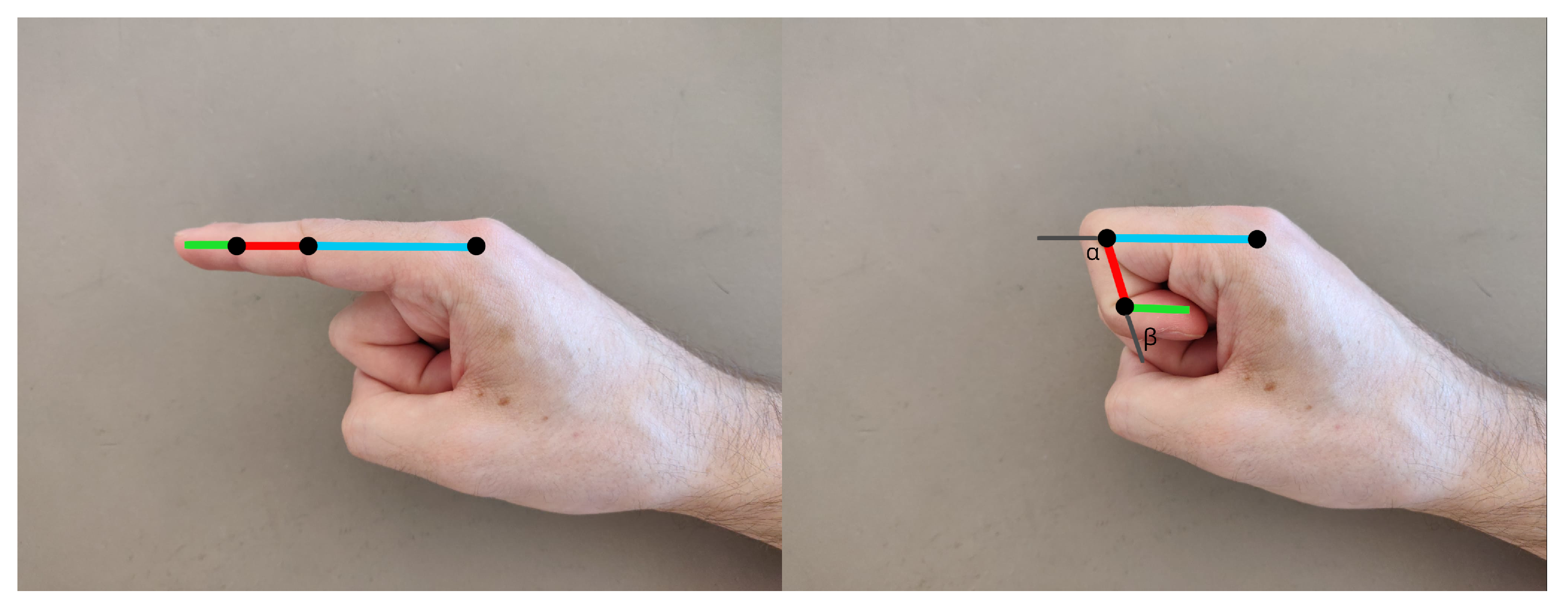
Firstly, the distal phalanges depend on the angle between the proximal and intermediate phalanges. A linear approximation is calculated in the relation between the angle of the proximal and intermediate phalanges and the angle of the distal phalanx. To find the factor between those angles, the straight finger angles and the fully curled finger angles are measured as shown in
Figure 2:
Obtaining these results in
Table 1:
So the function between the angle of the proximal and intermediate phalanges (
) and the angle of the distal phalanx (
) is described as:
3.3. IMU
As mentioned before, there are a lot of approaches to estimate orientation and improve performance and reliability of these sensors. Although the gyroscope is very accurate for a short period, it lacks precision in the long-term due to a bias in the angular velocity readings, and as we integrate, the error accumulates. On the other hand, IMUs also include an accelerometer which is not good for short duration because it is very noisy. However, it performs well in the long-term because it does not drift. So, the two together are meant to complement each other and take advantage of both sensor strengths. Some IMUs also include a magnetometer to correct for heading in relation to Earth north pole, but it will not be taken advantage of in this application because it is very susceptible to environmental factors that distort the magnetic field and is even more noticeable in industrial environments. So, most algorithms and approaches aim to tackle this sensor fusion problem to obtain the best of both sensors.
3.3.1. Gyroscope
Gyroscopes measure angular rate, usually in radians per second. This type of sensor is arranged in three axes to measure angular rate in 3D space. To track our orientation, we need to integrate the angular rate, but with the gyroscope there is no information about the absolute orientation in the global frame, so it is relative to the orientation when it started measuring and is not limited by any starting orientation.
The main advantages of the gyroscopes are the precision and the fast response time. However, the sensors carry a bias in the readings, and because orientation is tracked by integrating these readings, this bias accumulates an ever-growing error in the orientation. To minimize this effect, a calibration is applied (
Section 3.5.3) whichksubstantially improves the accuracy of the sensor. However, it is still not good enough to track orientation on its own.
The estimation of the orientation after reading the gyroscope measurements depends on the last orientation, the angular rate, and the delta time between samples. It is computed as:
where
is the last orientation, and
is the predicted orientation. This is also known as the attitude propagation.
3.3.2. Accelerometer
The accelerometer measures acceleration including gravity. It consists of three measurements in three axes and defines an acceleration vector. Intuitively, an object standing still only has gravity acting on it and describes the acceleration vector pointing downwards with a 9.8 norm. However, that is not the correct answer. In the case of gravity, it is interpreted as the surface below the accelerometer that is pushing it upwards at 9.8 m/s² counteracting the force of gravity. Therefore, a free falling accelerometer, although being accelerated by gravity, measures 0 acceleration in all axes.
So, the accelerometer does not measure coordinate acceleration; it actually measures proper acceleration, and that is the acceleration in its own instantaneous rest frame, which is different from coordinate acceleration.
In this application, only gravity acceleration is relevant because ultimately the goal is to obtain an orientation estimation, and other sources of acceleration will cause errors to that estimation. So, assuming the accelerometer is only being affected by gravity, it is possible to estimate pitch () and roll ().
The accelerometer measurements should be filtered with a median or mean filter to reduce noise. These filters act as low-pass filters, and because of that they are not best suited for the gyroscope as it degrades its speed advantage and short duration precision.
It is computed from the filtered readings
:
and leave the yaw angle (
) as 0 because it cannot be computed without a magnetometer. Roll, pitch, and yaw representation is a common type of Euler angle representation, more specifically Tait–Bryan angles. In navigation systems, the order of rotation is usually ZYX (or yaw, pitch, roll), and we convert to the quaternion form as:
This quaternion is most useful to initialize the glove orientation.
3.4. Euler Angles Complementary Filter
Because IMUs track angular rate along three axes, tracking the Euler angles to describe rotation is as simple as taking the increment of the previous angle and summing how much it rotated given the angular rate and delta time:
This solution is very simple and is very easy to fuse with the accelerometer data with a complementary filter because for the Yaw angle no fusion is computed. With quaternions, it is not so trivial and will be addressed in
Section 3.5.
where
is the gyroscope angle prediction, and
is the accelerometer angle prediction. The value of
is the trust in the estimation which will be explained deeper in
Section 3.5.
This orientation representation presents the gimbal problem. For some applications, this is not as relevant, for example quadcopters (assuming they do not flip) because their working range avoids the gimbal lock. This method was tested and in fact, when the hand or finger were straight up or down, then the other two axes would lock and perform the rotation around the same axis. For this reason, Euler angle representation was not adopted.
3.5. Quaternion-Based Complementary Filter
Complementary filters are the simplest methods for sensor fusion. They are simple to comprehend and are computationally inexpensive. They consist of a low-pass filter and a high-pass filter for each filter with the same cut off frequency. It can also be interpreted as simple scalar gain () that describes the trust in each estimation.
Let us look at a gyroscope–accelerometer sensor fusion example. We compute a gyroscope estimation and an accelerometer estimation, and we aim to estimate the true orientation of the body.
Here, quaternions and linear interpolation (LERP) are used because it is a good approximation for small differences between them. If a more accurate interpolation is desirable, a spherical linear interpolation (SLERP) can be used like so:
The gain describes how close it is from one of the two quaternions, hence the trust in each estimation. For example, a gain of 0 means we fully trust the gyroscope orientation prediction, and a gain of 0.5 means both estimations are equally trusted, and the result of the estimation is a quaternion right in the middle of both gyroscope and accelerometer quaternions.
This method works very well, for example, for quadcopters that only aim to correct the tilt and ignore the heading or when the magnetometer is used and the heading can be computed (note that quadcopters can still take advantage of heading to fuse magnetometer and GPS data).
Because an accelerometer lacks the heading information, a 0 degrees angle is assumed. However, the gyroscope can track heading from its original orientation, thus presenting a challenge when fusing both. Gyroscope orientation prediction will track heading and accelerometer orientation prediction will always try to pull the heading back to 0 degrees. This can be fine for some applications, but for the data glove this is not intended.
To get around this problem, a correction-based method can be used. It works by taking orientation prediction of the gyroscope and then correcting that prediction with delta quaternions. This method separates the correction of the attitude and correction of the heading from the accelerometer and the magnetometer, respectively.
However, because there are no magnetometer measurements, it is assumed that the magnetometer delta quaternion is a unit quaternion which means no correction.
3.5.1. Accelerometer-Based Correction
To find the accelerometer delta quaternion, the measured gravity vector is rotated from the local frame to the global frame by the inverse predicted quaternion of the gyroscope:
where
is the conjugate of gyroscope normalized predicted quaternion
, and
is the predicted gravity which has a small deviation from real gravity vector
. The accelerometer delta quaternion is computed from the rotation of
into
:
The delta quaternion is used interpolated via LERP with identity quaternion
by the gain
with value 0.005:
Normalizing the interpolated quaternion:
and finally correcting the orientation by multiplying the gyroscope predicted quaternion by the delta quaternion:
This way, the roll and pitch are corrected, but the heading angle is not affected and totally estimated by the gyroscope. If there was magnetometer data available, a correction for the heading could be computed with the respective delta quaternion.
3.5.2. Adaptive Gain
The current orientation estimation relies on the static condition assumed by the accelerometer measurements, but if the body is being accelerated by other forces than gravity, the estimations are evaluated using a false reference. However, the gyroscope measurements are not affected by linear acceleration; thus, they can still be trusted to compute an accurate orientation estimation.
The current constant gain fusion algorithm struggles to accurately estimate orientation in these conditions because it is optimized to static conditions. To tackle this problem, an adaptive gain algorithm can be used.
First the relative error
is computed:
where
a is the measured acceleration vector before normalization, and
g = 9.81 ms
.
From the LERP and SLERP definitions, the filtering gain
becomes dependent on the magnitude error
through the gain factor function
f:
where
is the optimal constant gain evaluated for static conditions, and
is the gain factor that is a continuous function of the magnitude error.
When the magnitude error does not exceed a threshold t, the gain factor is equal to one. This happens when the non-gravitational acceleration is not high enough to overcome the acceleration gravity. If the magnitude error is above the threshold, the gain factor decreases linearly until it reaches 0 at the second threshold t and over.
The values for the thresholds
t and
t were 0.1 and 0.2, suggested empirically by Valenti et al. [
24].
3.5.3. Calibration
A simple calibration was adopted in order to improve accuracy in the sensor readings. For the gyroscope, as noted before, it is known it carries a bias in the readings. This bias is fairly easy to approximate by sampling the gyroscope readings while the gyroscope is standing still. From those readings, the mean is computed for each axis, finding the offsets of the gyroscope. When reading the gyroscope angular rate, the raw readings are subtracted by the offsets computed from the samples.
No sensor is the same, so this process needs to be performed for every individual gyroscope. The initialization and calibration takes between 5 to 10 s for 200 to 300 samples, so to improve this performance, an offline calibration was attempted. The idea is to calibrate the sensors once and then load those values for the respective sensors.
For the accelerometer calibration, multiple readings were sampled, assuming the sensor is at rest and it should rest on the glove nearly flat. The mean of the samples was computed for each axis and the offsets, but in this case, the offsets are not all referenced to 0. The z-axis must be calibrated to −9.81 to account for gravity. This means that the moment the accelerometer was calibrated, it was assumed that its orientation was flat, so it is important that during the calibration, the hand is in a predefined known orientation, in this case, horizontal with straight fingers together and thumb in a natural position around 45 degrees. Essentially, this method of calibrating consists of changing the accelerometer frame of reference, but the gyroscope frame of reference is not adjusted, so the readings are not well interpreted. So, a better approach is not to calibrate the accelerometer but store the initial orientation computed from the accelerometer readings and correct the estimation before sending. The corrected estimation quaternion can be computed as:
Because only the pitch and roll are corrected by the magnetometer, over time the heading drifts from the true angle. One option is to restart, which will reset the position and calibrate every sensor again, but the re-calibrate is not strictly necessary because the drift usually is faster than the deviation in calibration. For convenience for the user of the glove, a reset button was added to reset the position from the accelerometer to when the orientation was first initialized (Equation (
6) readings without re-calibrating again).
4. Results
The simulation and visualization cannot be ignored, it is always crucial for these type of applications. It is possible to debug directly from the output in JSON format and interpret the meaning of the quaternions, but it does not scale well, nor is it a reliable method because it is very prone to error. On the other hand, a simulator offers an intuitive interface with humans, easy to interpret for our brains without looking at the numbers being output.
In this application, the support of forward kinematics and graphical context are the main features when looking for a simulation tool. The game engine was the choice. It does not feature the most realistic physics and simulations because it aims to be fast and compromises some accuracy, but for the needs of the application, it does not need to actually simulate a lot of the real world, it just needs to set orientations, locally and globally, of the objects and output somewhat realistically to the screen. Although this application was developed for this engine, some others can be used with the respective adaptations.
A working simulation was the main goal during the first stages of development as stated before. The rest of the development progresses faster with a visualization tool. Firstly, the features were tested to reaffirm that the simulation fits the application needs. An empty 3D project was created and only had a scene with a directional light and a camera, so the first step is to create the hand model and it was performed from scratch using ’s native 3D objects. To control the position, orientation or scale of the objects in the transform component was used. This component has a tree structure, where it holds children’s transform, and it is how it computes forward kinematics. When the parent transform moves, all its children are attached and also move.
To construct a hand, the transform and object hierarchy is rooted in the arm, followed by the wrist. The palm is attached to the wrist, and the base of the fingers are children. Each finger then has one child, the proximal, and in each proximal, the intermediate, and the intermediate holds the distal. The tree structure is better visualized in
Figure 3.
The rods, spheres, and disc objects are attached because they hold a mesh renderer component which is what makes it possible to visualize. The objects that the transform will manipulate just hold the transform. For default, these
’s prefabs come with capsule collider and need to be removed or disabled. The end result is shown in
Figure 4.
To test it, the hand controller script was created and attached to the hand object. This way it is possible to manipulate the transform and its children. The test consists of just rotating the wrist and folding the fingers on loop at a given velocity. The test was successful and proved that is capable of setting the orientation relative to the parent which is the same format as the output of the microcontroller.
The scripting of the
game engine is very complete and supports almost every feature of the
environment, including UDP library. Because the game engine calls the function “Update” in the script component for every frame, if the call to read data from the UDP socket is blocking, then it blocks the loop until the data arrives which is undesirable. Ideally, the simulation runs continuously, and when new data arrives, it updates. When there is no new data, it can perform other tasks. Usually, reading streams from sockets blocks the program, but the library also supports asynchronous programming which fits well with the nature of the simulation logic. It is an event-based system, where the event to listen for is defined and a handler (usually a function) to execute when the event is triggered. In this application, the event to listen for is received data in the UDP socket. When the data is received, it is stored in a variable accessible by the “Update” method of the script, usually inside the class’s script. When it is received, it also flags it to let the “Update” method know it needs to parse that data and update the hand object. Because it runs asynchronously, race conditions must be handled with care. If the data is received while parsing the previous data, it is possible to corrupt the data in the middle of parsing. So mutexes were used when writing or reading the shared resource assuring atomicity of the operations, blocking access of other operations to the shared resource while another operation is handling it. This asynchronous approach, summarized in
Figure 5, makes it possible to decouple the speed of the microcontroller output and the game engine speed, solving the issues of synchronization.
To test the UDP connection, a script was implemented that inputs a user string and sends it through UDP to localhost. The server side ( script) reads it and logs the result. The test revealed it was a viable solution, also capable of reading streams of data continuously.
Whether the solution could handle non-stop streams of data simulating high frequency data outputting was also tested. So, a script that just sends the value of an incremental counter in an infinite loop was implemented, and the asynchronous solution, in fact, was working properly.
counter = 0
while True:
bytesToSend = str . encode ( f" Message:␣{counter}" )
UDPClientSocket . sendto(bytesToSend , serverAddressPort)
counter += 1
The two last tasks the script must perform are the parsing of the received data and the update of the transform of the correct objects. The game engine has its own serialization implementation and includes JSON serialization and deserialization tools. It is only required to define the structure in a class or struct, add the “Serializable” attribute, and the JSON tools create the object from the JSON encoded string.
[Serializable]
public struct FingerPose
{
public SQuaternion[] joints;
}
[Serializable]
public struct HandPose
{
public SQuaternion wrist;
public FingerPose[] fingers;
}
The “SQuaternion” type is a custom serializable quaternion because the quaternion type does not support serialization by default. It just stores w, x, y, and z values and implements implicit operators to allow an easy conversion between the native quaternion type supported by so it can be used like so:
SQuaternion s_quaternion = new SQuaternion(0, 0, 0, 1);
Quaternion quaternion = (Quaternion)s_quaternion;
To perform the rotations on the objects,
handles it when setting the property “localRotation” on the transform component. It expects a quaternion and sets its orientation in relation to the parent transform. One issue that immediately surged is that the microcontroller and the simulation were not using the same reference frame.
Figure 6 helps visualize the frames of reference.
The frame of reference transformation is defined by the transformation matrix from microcontroller frame to simulator frame
:
So, before setting the local rotation of the objects, the frame of reference transformation is computed inside the function “ToFrameOfReference”. It takes the microcontroller quaternion as an argument and returns a new quaternion in the simulator frame of reference:
private Quaternion ToFrameOfReference (Quaternion q)
{
return new Quaternion(q.y, -q.z, q.x, q.w);
}
Finally, it assembles the parsing and the rotation of the objects, each frame, if it has new data, runs:
HandPose pose = ParseGloveData ();
wrist.localRotation = ToFrameOfReference ((Quaternion)pose . wrist);
for ( int i = 0; i < 5; i++)
for (int j = 0; j < 3; j++)
fingers[i] . joints[j] . localRotation =
ToFrameOfReference ((Quaternion)pose . fingers[i] . joints[j]);
To test that everything was properly working, a test very similiar to the previous one was performed but sending valid JSON data. It also takes input from the user to the target angle of the wrist and forms the JSON payload with all other quaternions as identity quaternions, which means no rotation. The test successfully validated the correct parsing of JSON data and the correct assignment of the orientation in the right frame of reference.
5. Real Prototype
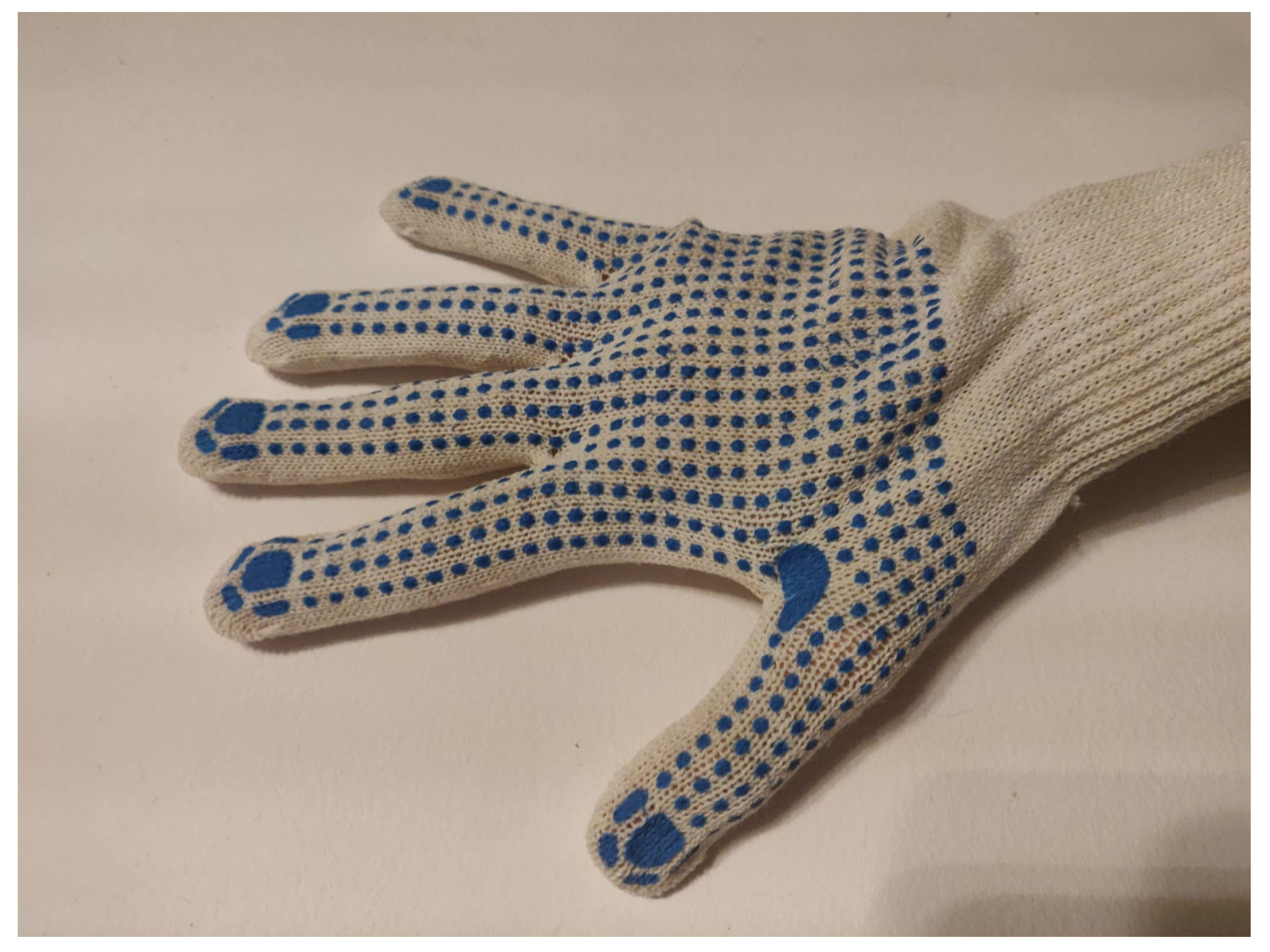
The glove design presented a challenge on two fronts: glove choice and wiring solution. Ensuring the sensors are tightly coupled with their respective links to accurately capture the movement boils down to the glove choice—if the glove is loose on the hand, the sensors attached do not accurately follow the movement, but stiffness helps keep the sensors steady. Gardening gloves were the first idea to try, but it was decided they were often too loose, and certain gestures, such as lifting the proximal, would create a fold exactly below the sensor. On the other end of the spectrum, surgery-like gloves that are very tight were considered, but mounting the sensors is not straightforward. So, a glove made out of wool, shown in
Figure 7 was tried because it gave the most options. It was tighter than the gardening ones, and the sensors could be stitched to it. The sensor location is flexible to some extent in contrast to the others that could only fit one way.
I²C communication protocol only requires two connections and is the best case scenario wire-wise, but the sensors also need 3.3 V power and ground, and half of them need to pull the I²C address pin high. In total, half the sensors need four wires, and the other half 5 wires for the total 12 sensors. This amount of sensors in a such a small space results in the wires bumping each other, such as shown in
Figure 8, and inadvertently moving the sensors causing false estimations. This solution is not optimal, and to get around the problem a bus-like wiring was attempted. Because sensors are all powered by the same device and voltage, and the I²C works as a bus, it allows for a cascading wire layout where the intermediate sensor connects to the proximal and proximal to the multiplexer reducing the floating wires roughly by half, such as shown in
Figure 9. This also reduces the chance of long wire communication instabilities although it did not reveal being an issue. This design has a flaw of overloading the current of the power in the wires nearest to the source because the sum of the currents drawn by sensors flows there. Increasing the current, the voltage drop in the wire increases proportionally, the voltage at the further sensors goes lower, and the fluctuations can cause instabilities. In this design, that was not an issue because only two sensors are cascaded, except the thumb that cascades three sensors.
As a prototype, the simplest communication protocol was serial, but it is wired, which sometimes may limit flexibility or restrict the user’s movement and, generally, wireless (if inside performance requirements) is preferable. The two main options of wireless solutions are changing the microcontroller for one that features a wireless solution or adding a module for the microcontroller to interface. A popular module is the which can be interfaced by SPI or UART, and it is fairly simple with a lot of documentation. Adapting the current solution for any of the two proposed wireless solutions is straightforward. If the microcontroller were to be swapped, the only requirement is to keep the ARM processor architecture not to cause conflicts with libraries, but would handle the rest. In both solutions, adapting the output function is the main change to interface with the chosen wireless feature. Ideally, the wireless solution is WiFi to connect to the simulator network and communicate directly with through UDP, but it is possible to adopt another wireless solution such as and implement a bridge such as the one implemented in for serial.
Binary encodings are the most efficient sending data and are very popular for real-time applications that are robust to errors, meaning if there is an error in transmission, the system is not fully compromised or there are mechanisms computationally cheap to detect errors and ignore those payloads. In this application, the priority of the glove is to stream the data fast, and it is assumed that the responsibility lies in the receiver to handle errors. For these reasons, binary encodings fit the application’s requirements, and serialization should be optimized from the current JSON encoding. A promising solution to better serialize is ’s . It is a tool for serializing cross-platform and cross-languages, and compiling it produces the code for the specified languages, meaning there is no metadata being sent, and both ends of the communication know the structure offline. The idea was not explored in this application but revealed being very suitable to solve the JSON serialization problems.
The results of the orientation estimation solution were evaluated empirically by comparing the movement of the user’s hand with the simulation. A set of commonly used hand poses were performed to test the capabilities and limitations of the current solution.
In
Figure 10, the pose of the hand is accurately depicted. This pose is useful to test basic functionalities because it does not feature complex orientations. Two fingers are fully curled, the other two are fully extended, and the thumb is to the side near the initial position.
The second demonstration (
Figure 11), where the index and the thumb are connected, presents other challenges and reveals some imperfections. In
Figure 11, the fingers do not connect and do not represent the orientation as accurately. This is mainly due to two issues: the wires and the model. The wires are sufficiently stiff, and the fabric does not keep its shape, allowing it to be pulled so the sensors are not in the same orientation as the hand, causing the error. This error is common when curling the fingers and also when the wires of another sensor obstruct other fingers movement and stretch the fabric.
Figure 12 also confirms it, as the fingers should be slightly more curled. The other issue is the thumb in the model; it is very far, and the scale is not adjusted because the model used for all the fingers is the same. In the other four fingers, it is not very noticeable, but in the thumb, the simulation is not represented so well. However, the orientation matches. The last demonstration
Figure 13 combines some poses, such as curled, extended, and connecting fingers, and the straight fingers (index and pinky) show the ability to track lateral movement. This pose also shows the wire problem, where the pinky finger is obstructed by the wires of the ring finger. In this case, the orientation estimation was not affected, but it is important to note the issues in user experience. Comparing the results with the ones mentioned on the literature review, the presented solution is cost-effective and easily replicable. The configuration used in this approach is innovative and expandable, being an excellent starting point for further work and scientific contributions.
The demonstrations are fallible because of the repeatability in initial position and calibration, and because the assumptions of the position of anatomy in the simulation environment. This can be easily solved by adjusting the finger scale and placement, mainly the thumb. However, the results were still satisfying, proving the concept and revealing the main issues to address in future work.
6. Conclusions and Future Work
The current glove design is not the most flexible in terms of sizes and reliability. Although the fabric was chosen to be flexible, it is also a problem. The same way it facilitates adjustments, it also enables errors in positioning. The implementation of the orientation estimation is error tolerant to a point but assumes the IMUs are on top of the phalanx, nearly flat. The fact that there is only one glove size presents a problem for smaller and larger hands. A possible solution is that instead of attaching the sensors to the glove, make it modular in a way the sensor array can be worn on top and adjusted for any kind of glove or even without a glove. Some mechanism, such as strapping it around the finger, might be viable, but the palm sensor may need another solution.
The distal phalanx interpolation was not vastly explored, leaving room for improvement, considering that the linear interpolation implemented in this application was simple. Possibly with more anatomical research, a better estimation can be achieved. There is also the possibility of not interpolating it but tracking the distal phalanx for each finger by adding four more IMUs (the same way that the thumb’s distal phalanx is being tracked). The I²C multiplexer still has two empty channels that can connect up to four IMUs, so there is no need to expand.
To solve the heading drift, the most common solution is by adding a magnetometer and adding a heading correction step in the filter. However, in this application, the glove was mainly targeting industrial application, and in these environments magnetometers struggle to accurately measure heading due to high soft and hard iron disturbances, even with calibration, so it was ruled out from the beginning. Other solutions were not explored, but the current implementation leaves room for the heading correction without remaking any of the current work. In fact, only proximal phalanges have that degree of freedom, and it is possible to simplify the problem even further by reducing the degrees of freedom of other phalanges that can only move up and down, but currently all movement is tracked. A possible approach is looking at sensors that measure angles in just one axis such as flex sensors. They are not very precise, but since they are just required for a slow correction, it is not a problem. However, their placement in a glove can be challenging because there is no easy pivot point laterally.
Calibration revealed being a big role in IMUs precision and accuracy and even more relevant to maximize performance of low-cost sensors. As mentioned in
Section 3.5.3, gyroscopes have a zero-offset that is measured during initialization, and it was attempted to measure offline but failed because that offset changes with temperature and will change during usage and is not currently accounted for. A way to more accurately calibrate the gyroscope, is to measure the offsets at a range of temperatures and during operation dynamically compute the offset, such as proposed in the paper [
35]. The
sensor also includes a temperature sensor, so it is still a suitable choice. Another approach to tackle the gyroscope drift can be using other sensor fusion algorithms, such as the Magdwick filter that implicitly estimates the gyroscope bias, and the magnetometer measurements are optional [
29]. In addition, the different calibration sample sizes hinted that, at a certain sample size, the gains in gyroscope offset estimation accuracy decrease. Because the user must stand still during this calibration, if it takes a long time, the chances of the user inadvertently moving increase, but the impact of the error varies with the magnitude of the movement. Because there are more samples, these errors are not as relevant. In addition, a very short sample does not estimate the offset with enough precision.


 ,
, 


