
UAV Swarm Real-Time Rerouting by Edge Computing D* Lite Algorithm

1
Department of Automation Engineering, National Formosa University, Yunlin 632, Taiwan
2
Department of Power Mechanical Engineering, National Formosa University, Yunlin 632, Taiwan
*
Author to whom correspondence should be addressed.
Appl. Sci. 2022, 12(3), 1056; https://doi.org/10.3390/app12031056
Submission received: 1 December 2021
/
Revised: 15 January 2022
/
Accepted: 16 January 2022
/
Published: 20 January 2022
(This article belongs to the Special Issue Human-Computer Interactions)
Abstract
:Seeking to give unmanned aerial vehicles (UAVs) a higher level of autonomous control, this study uses edge computing systems to replace the ground control station (GCS) commonly used to control UAVs. Since the GCS belongs to the central control architecture, the edge computing system of the distributed architecture can give drones more flexibility in dealing with changing environmental conditions, allowing them to autonomously and instantly plan their flight path, fly in formation, or even avoid obstacles. Broadcast communications are used to realize UAV-to-UAV communications, thus allocating tasks among a swarm of UAVs and ensuring that each individual UAV collaborates as an integrated member of the group. The dynamic path programming problem for UAV swarm missions uses a two-phase tabu search with a 2-Opt exchange method and an A* search as the path programming algorithm. Distance is taken as a cost function for path programming. The turning points of no-fly zones are then increased and expanded based on drone fleet coverage, thus preventing drones from entering prohibited areas. Unlike previous work, which mostly considers only single no-fly zones, this approach accounts for multiple restricted areas, ensuring that a UAV swarm can complete its assigned task without violating no-fly zones. A drone encountering an obstacle while traveling along the route set by the algorithm will update the map information in real time, allowing for instant recharting of the optimal path to the goal as a reverse search using the D* Lite algorithm.
1. Introduction
Unmanned aerial vehicles (UAVs) are a type of unmanned aircraft system that is remote controlled from a ground station. UAVs were initially used mainly by militaries to conduct “dull, dirty, or dangerous” missions [1], including reconnaissance or air-to-surface ordinance strikes. With the rapid development of related technologies, UAV applications have expanded too many other fields, such as aerial photography, product delivery, agriculture, science, and racing.
Complicated missions in uncertain environments frequently call for the use of UAV swarms, which distribute tasks to individual drones, with applications including formation flight, inspired by the formation flight behavior of birds. In 2015, the United States Air Force (USAF) proposed the “loyal wingmen” concept [2], in which support drones not only help the leader engage in reconnaissance or airstrikes but also protect the leader from attack. This technique reflects the application value of UAV swarms. Other swarm applications could allow different drones to carry different sensing devices or additional sensors to enhance mission flexibility and robustness in the face of uncertain and changing environmental conditions [3,4].
A UAV swarm requires a control system that allows for effective cooperation on complex tasks. A multi-agent system for controlling a UAV swarm can be roughly divided into two architectures: centralized and distributed control systems.
A centralized control system is composed of a ground control station (GCS), which holds environment and map data, as well as information about the status of all UAVs. Algorithms assign mission tasks to each UAV through the ground control station, with instructions issued via communications equipment to each UAV controller for coordinated task execution. Ground station control is the most common system architecture for controlling autonomous UAV flight. The advantage of this architecture is that the ground station can calculate algorithms and assign tasks using a high-performance computer. Previously, in the authors’ research laboratory, an open source Mission Planner GCS for swarming multiple UAV technology was developed with great success [4,5]. However, the execution of such swarm missions is overly dependent on ground station guidance and control; thus, the mission range is restricted by the effective communication distance between the drone and the ground station. Drone flight is controlled through the central terminal, leaving individual aircraft unable to adapt quickly to unexpected conditions, such as obstacles.
Distributed control is a solution that addresses these drawbacks in centralized control systems. One type of distributed control system is called an edge computing system, frequently seen in architectures supporting Internet of Things (IoT) applications. Broadly defined, an edge computing system is one in which all computing occurs outside the cloud and at the edge of the network. In recent years, the efficiency requirements of IoT devices have increased. With limited local resources, mobile edge computing has emerged as an effective solution, providing drones with more reliable line-of-sight communications and routes than ground-based vehicles [6]. This approach is easy to manage, and increased attention has focused on the use of edge computing for UAV applications [7,8,9]. Using an edge computing system for drones, the cloud can be regarded as a ground station that distributes all calculations to the edge (i.e., the drones). This architecture can provide a higher level of automatic control, allowing drones to make decisions autonomously through their onboard computer while also providing communication between aircraft.
In 2015, the United States Federal Aviation Administration (FAA) and National Aeronautics and Space Administration (NASA) jointly proposed an operational concept for a remotely controlled drone flight management system—Unmanned aircraft system Traffic Management (UTM)—to improve low-altitude flight traffic safety [10]. This conceptual approach is divided into four technical stages: the message architecture of the data exchange, position sensing and avoidance, position tracking, and communication and navigation. Among these, the development of the third stage began in 2018, with a particular focus on drone applications using avoidance technology to enable UAVs to safely fly in designated areas without line of sight to the operator. The development of the fourth phase began in 2019, focusing on UAVs flying outside the line of sight in densely populated cities, requiring not only a communication network architecture and monitoring system but also the drone system’s ability to process large-scale incidents.
Based on the above research, autonomous task performance ability can be developed as a necessary condition for future development tasks. In this approach, ground control still plays an important role; flight task execution for multiple UAVs should not rely exclusively on the ground station. Rather, edge computing approaches should be integrated to improve the autonomous computing capabilities of each drone to adapt to changing conditions in real time. Therefore, the present study sought to develop a long-distance intelligent multi-aircraft dispatch system to realize an autonomous multi-rotor path and multi-waypoint task dispatch, along with the automatic execution of large-area tasks. A route planning algorithm was developed to identify the shortest path while considering the mission area as multiple navigation areas subject to restricted navigation. Dynamic planning was conducted using the D* Lite algorithm, such that each drone could achieve real-time obstacle avoidance and route re-planning [11].
2. Methods and Materials
The software in this study was composed of DroneKit, an open source Python library [12]. It can be executed on Linux, Mac OS, or Windows, as long as the flight control board is compatible with the MAVLink protocol [13], which is a very compact messaging protocol widely adapted for drone communication. Three functions were used in this study. The first connected to the flight control board. The second obtained vehicle status information. The third guided the drone to a designated target point. Figure 1 shows the software flow chart. At first, the drone will wait for instructions from the small ground station. When it receives the take-off command, the drone will climb to the specified altitude, and then receive the target point and the longitude and latitude coordinates of the no-fly zone. When it receives the standby command, the drone selects a long flight path and then commences its task.
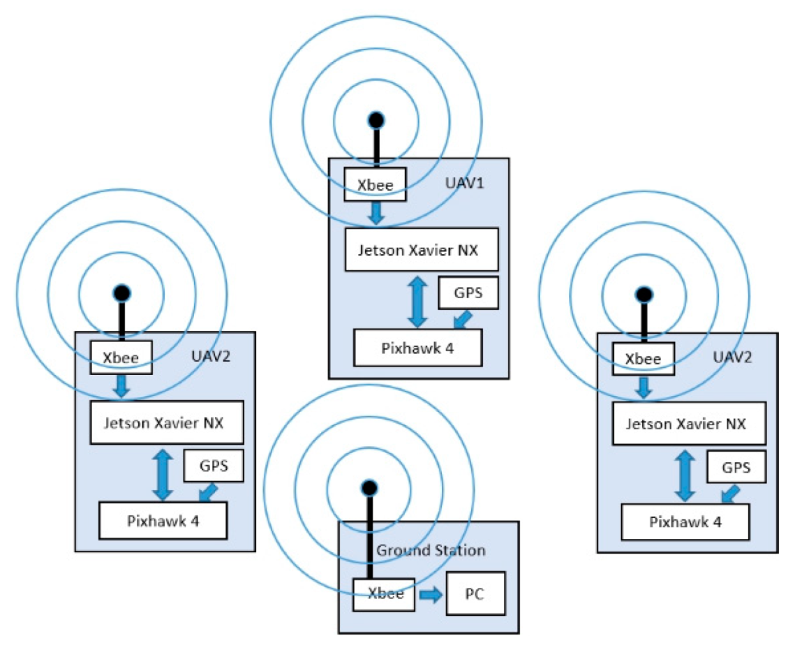
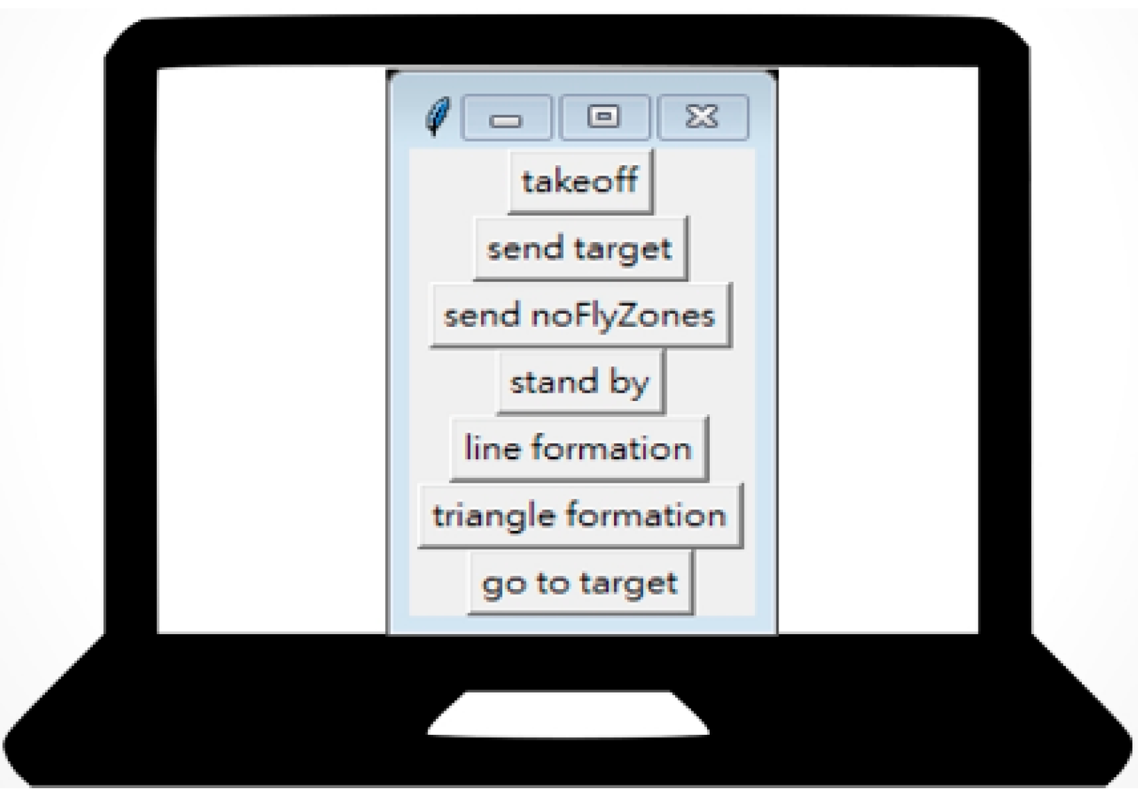
Figure 2 shows the overall system schematic, consisting of three drones, each equipped with edge computing systems. Each drone is equipped with a Pixhawk 4 as a flight controller and a Jetson Xavier NX embedded computing board for algorithm processing. Communication between drones is achieved using the broadcast function of the XBee wireless transmission module. Apart from the global positioning system (GPS), the drones do not carry any environmental sensors. As shown in Figure 3, the system included a small ground station to simulate a signal for a formation change. The self-developed ground station comprises a laptop computer with an XBee wireless module, which is responsible for flight monitoring and providing the drones with target waypoints and no-fly zone information by GPS coordinates.
2.1. Formation Control
The wingman drones are responsible for maintaining formation by calculating their positions in real time. Figure 4 shows the flowchart of the wingman function. When the wingman receives a linear or triangular formation command from the ground station, it starts to calculate the position it should follow using Equations (1) and (2). Llon and Llat represent the longitude and latitude coordinates of the lead plane, respectively. Flon and Flat, respectively, represent the latitude and longitude coordinates to be followed by the wingman. D represents the distance between the leader and the wingman. A represents the angle between the leader and the wingman.
2.2. Communication Method
This study used a customized communication format to share ID number, latitude, longitude, altitude, heading, battery voltage, leader number, and flight mode. Figure 5 presents the data content of the communications protocol.
2.3. Optimum Path Programming
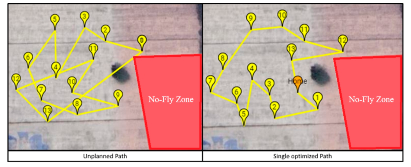
Unmanned vehicle mission target points were randomly assigned. A lack of a trajectory plan will lead to inefficient task performance and an increased workload. The system’s route planning algorithm addresses this issue by planning multiple paths and selecting the optimal route. Figure 6 shows a single-path (single UAV) solution, while Figure 7 shows a multi-path (three UAVs) solution. In Figure 7, although a set of optimized paths with minimum distance without touching the no-fly zone is generated, it is obvious that an unexpected obstacle (a tree) still lies on the red path. This is also one of the problems that this research aims to solve.
In 2017, the Autonomous Unmanned Vehicles Laboratory (AUV Lab) at National Formosa University (NFU) completed the multi-vehicle path planning algorithm [14], combining the rules and principles of the tabu search method, the 2-Opt exchange method, and the A* search method to multi-load the multi-traveling salesperson problem with performance that exceeded the traveling salesman problem library (TSPLIB) in terms of convergence effect. However, only the avoidance distance of a single UAV is considered when avoiding the restricted navigation zone; thus, in performing group tasks, it is impossible to effectively prevent wingman drones from crossing into the restricted navigation zone. The 2019 version of the Mission Planner ground guidance station developed by AUV Lab was successfully applied for the path planning of drone groups, using various wireless data transmission modules to simultaneously issue control commands to multiple vehicles, with feasibility verified using five UAVs [15]. The star-shaped topology established by the ground control system, combined with wireless communication transmission, allows the drone cluster to be controlled for path-planning tasks. This task mode has had a profound impact on this research, but because the task is completely reliant on ground-based guidance and control, drones are still restricted from performing many tasks.
Changing the control architecture allows drones to perform tasks autonomously. When encountering obstacles while flying in an unknown environment, drone flights are divided into two phases using the real-time mission path. The first phase is the group path controlled by the ground station. Planning includes two algorithms: the tabu algorithm for group UAV path planning and the A* search algorithm for no-fly zone avoidance. The second stage is autonomous task execution and real-time path redrawing, so that the UAV can complete the task autonomously in an uncertain task environment without relying on the ground station, using the D* Lite search algorithm to redraw the task path in real time based on the received obstacle information and achieve avoidance. Then, according to the rotorcraft action mode, the D* Lite algorithm’s moving method is modified to allow the dynamic programming algorithm to be reasonably applied to the drone mission in the real environment. The D* Lite dynamic programming algorithm flow is shown in Figure 8.
2.4. Tabu Algorithm
The calculation step of the tabu search method first establishes an initial solution, and then finds the best neighboring solution or the solution that meets the exemption rule on a moving basis. That is, it searches for a better solution in the area adjacent to the current solution. It iteratively moves the current solution to a region closer to the best theoretical solution, as described below.
2.4.1. Move
Move refers to the move from the current solution to another solution through the movement’s attributes; that is, it selects the best move among all adjacent solutions expanded by the current solution to approach the best solution. The method of movement depends on the problem, and most comment methods are swap, insert, 2-Opt, K-Opt, etc. From the previous study in the AUV Laboratory [16], according to different cost functions (shortest total path, shortest mission time, equalized work loading, etc.), the tabu + 2-Opt method has a well-balanced performance between finding the best solution and computing time; hence, this study used the 2-Opt method.
2.4.2. 2-Opt Exchange Method
This is a method for changing the route order. Originally designed for the traveling salesman problem, this approach is now widely used to change route orders for a variety of routing problems. It can be divided into inter-route and intra-route switching, thus preventing route crossing.
2.4.3. Tabu List
The tabu list stores the searched solutions to prevent the algorithm from falling into a local solution. The storage rules are roughly divided into long-term memory, mid-term memory, and short-term memory. The longer the memory length, the better the mobility of the best solution. To maintain the diversity needed to achieve a global search effect, this study used 10 memories as the memory length.
2.4.4. Aspiration Level
Some moves are on the tabu list; however, if a tabu move is selected and a solution better than the one currently being searched is found, the move will be excluded from the tabu list, and the current tabu move will be accepted.
2.4.5. Stopping Criterion
When the search phase reaches the stopping criterion, the best solution currently searched is the final solution. The tabu search stopping criterion can be generally divided into four types: the calculation reaches a preset maximum number of iterations, the objective function has not continuously improved over multiple iterations, the maximum acceptable CPU time is reached, and the calculation is preset to accept the value of the objective function. This study used the first two criteria.
In the single-path tabu calculus, if the global best solution lasts for 10 generations and does not improve, the single-path calculus is terminated and the process proceeds to the next step. In the path exchange calculation between multiple devices, if the global best solution lasts for 30 generations and does not improve, additional route exchanges between devices cease, and the next calculation step is performed. This stop condition is used to search for three generations until the best solution is obtained.
2.5. No-Fly Zone Avoidance
In 2020, the Civil Aeronautics Administration of the Republic of China (Taiwan) amended the Civil Aviation Act to include a “Special Section for Remotely Controlled UAVs”, announcing areas where UAV use was restricted or prohibited, including airports. Article 99-13 of the Civil Aviation Act forbids the use of remote controlled drones flying within a certain distance of restricted areas to ensure public welfare and safety [17]. Therefore, following route planning, it is necessary to determine whether the chosen route conflicts with the no-fly zones. This is accomplished using the route planning method of the A* search algorithm, which considers the radius of group formation.
The A* search algorithm finds the lowest cost path with multiple nodes, combining best-first search and Dijkstra’s algorithm to find an optimal path while carrying out heuristic search to improve the algorithm’s efficiency.
In the A* search algorithm, the cost function f(n) of the computing core is Equation (3), where g(n) represents the travel distance function from the starting point to any target point n, and h(n) represents the estimated distance function from any target point n to the endpoint. When h(n) = 0, the target calculation ends. This study used Euclidean distance, which is generally called straight-line distance.
The A* search algorithm is a simple and practical method in which its core rules are Open, Close, and Dead End. Open represents the current expandable point, and it will be cleared after each expansion. Close represents a point that has been traversed and cannot be expanded again. When the calculation is over, the points stored in Close are connected in sequence to form the final path. Dead End represents points that cannot be expanded and in which the calculation process will not be cleared.
2.6. Dynamic Avoidance Algorithm
In 2012, Al-Mutib and Al-Sulaiman [18] proposed a method that included both static and dynamic path planning methods, using the D* Lite calculus to allow multiple robots to avoid obstacles and reach the endpoint in a custom obstacle map. Although this task does not consider the traveling salesman problem of multiple target points, and the realization result is limited to simulation, it provides important inspiration for research on dynamic avoidance methods.
D* Lite (Dynamic A* Lite) was developed by integrating the characteristics of lifelong planning A* and D*. The D* algorithm was re-implemented based on the LPA* algorithm. D* Lite has a high movement cost when the environment changes. The estimated function uses a starting point, a fixed target point, and a reverse direction search, constantly updating the current position to the new starting point to re-estimate the true vehicle movement cost of the vehicle to obtain a better path solution.
In this study, the D* Lite search algorithm was also used in dynamic obstacle avoidance path planning. However, to apply the D* Lite algorithm to multiple quadcopter drones cooperating in a single task after group route planning, this study modified the traditional D* Lite to meet certain conditions. First, the movement method in the algorithm must be matched by the drone’s actions. Latitudes and longitudes are used directly as the map coordinate system. If the original D* Lite is used to find the next point to generate the movement path, the computational loading of the edge device will greatly increase due to the excessive latitude and longitude coordinates. Due to the hardware limitations of the flight control board, the UAV will clearly decelerate when passing the target point in the guided mode, and excessive moving point density will unacceptably slow the UAV’s flying speed. Therefore, this study referred to the vehicle movement mode along the obstacle apex in the D* Lite algorithm. As proposed by Z. Luo et al. in 2020, this study used the D* Lite algorithm to provide a shorter path that is more suitable for UAV applications [19]. Its characteristic is to change the vehicle’s movement such that the vehicle is no longer limited to movement in eight directions but can move from any angle to the obstacle apex at the lowest cost. While avoiding the obstacle, it also avoids excessive turning points in the route, making it suitable for use in rotorcraft that cannot sustain excessive yaw movement. Combined with the method of expanding the no-fly zone to produce turning points and thus avoid restricted areas, this allows the UAVs to identify obstacles during mission execution, and complete avoidance along the obstacle apex, as shown in Figure 9.
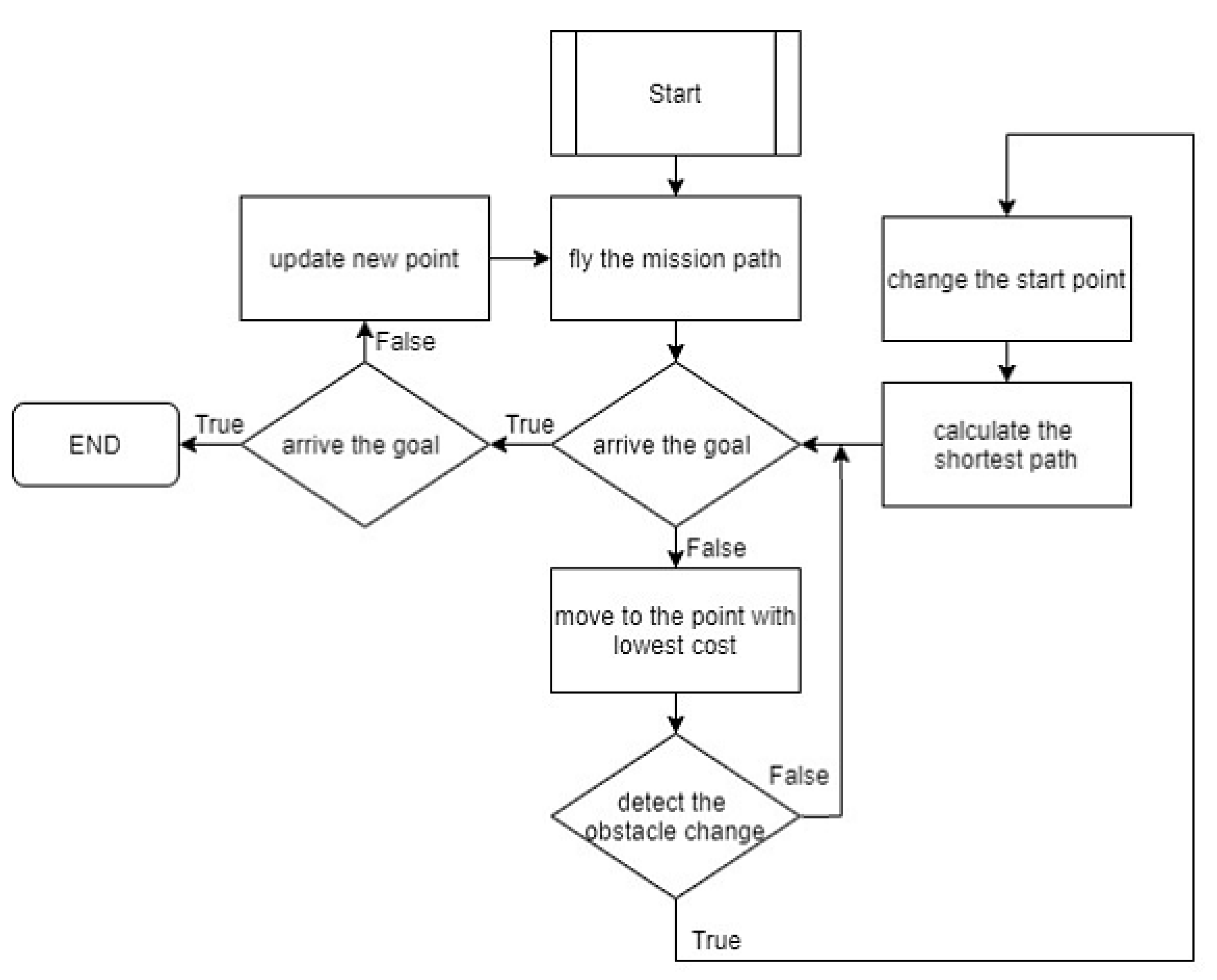
The improved D* Lite algorithm is applied to each drone flying along the mission route. Each drone uses received obstacle information and known information to identify obstacles blocking the route to the target point. This dynamic route planning allows the UAV to reach the target point smoothly. The algorithm flow chart is shown in Figure 10.
2.7. Simulation Equipment
MAVProxy is designed as a simple GCS for any flight controller supporting the MAVLink protocol [20]. It is a command-based ground station software for developers. To use a graphical user interface for monitoring, it can be complemented with other ground station software applications, such as Mission Planner, APM Planner 2, or QGroundControl [21,22,23]. Further, it has many interesting functions, such as message forwarding from the UAV to other GCS via the User Datagram Protocol (UDP) network. This function is used to monitor the mission trajectory during flight.
The monitoring station is designed to monitor the trajectory of flight missions based on a GCS mission planner. It is a simulation tool developed as part of this study. In Figure 11, the monitoring station gathers information from MAVProxy via Wi-Fi and displays the trajectory.
2.8. Experimental Drones
Compared with fixed-wing aircraft, a quadcopter can deploy on a smaller site and does not require a runway for takeoff or landing; hence, it was chosen for flight experiments. The drones used in this study were three 450-class quadcopters, which consisted of four motors, four electronic speed controls (ESC), four propellors, and a carbon-fiber frame with a power distribution board. Based on this flying testbed, a Pixhawk 4 flight controller, a Jetson Xavier NX onboard computer, an Xbee wireless communication module, a 2.4 GHz receiver, and a battery were integrated into each drone, as shown in Figure 12. The total weight of the experimental drone, including a 3S 4200 mAh LiPo battery, was 1474 g, and the flight duration was about 6 min.
2.9. Hardware and Software Performance
In previous UAV work, the AUV laboratory developed a task assignment GCS in which the C# language program code trajectory optimization algorithm was embedded and ran on this PC-based GCS. Due to a different system architecture, a UAV with native computation ability through the use of Jetson Xavier NX is required for rerouting purposes by onboard real-time edge computing. Before the real flight experiment, the algorithm programs were tested on both the PC and the Jetson Xavier NX platform. The computation capabilities of a PC with an intel 8th general CPU far exceed those of the embedded Jetson Xavier NX computer, but Jetson Xavier NX still provides acceptable computation speed and can be carried on a small size UAV.
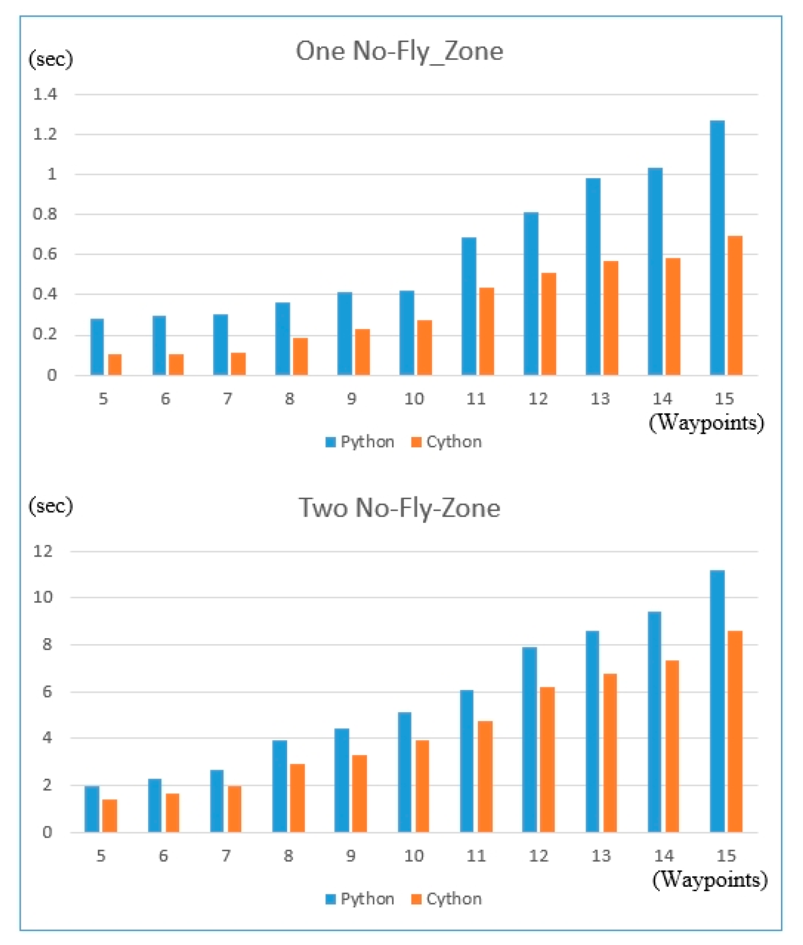
The calculation time of the trajectory algorithm was used to compare the performance of the PC and Jetson Xavier NX. Two programming languages, Python and Cython, were separately used to program the algorithm, which was then run on two different computers for performance comparison by programming language. Algorithm parameters for both groups had 5 to 15 targets and 1 to 2 no-fly zones.
Cython is a programming language that combines the syntax of C and Python. It can be simply thought of as adding static syntax to Python, allowing developers to maintain most of the Python syntax without major adjustments. Cython can directly compile a program into a binary, thus providing significant performance improvement over Python.
According to the system flow chart in Figure 1, the dynamic path programming using edge computing can be sorted into two kinds of sub-functions: (A) pre-flight optimization—that is, multiple vehicle path optimizations, including known no-fly zone avoidance; and (B) in-flight rerouting, a real-time unknown obstacle avoidance based on its dispatched route.
For pre-flight optimization, Figure 13 shows the performance of using Python on both Xavier and PC. For a no-fly zone and 15 target cases, the Xavier took 1.25 s, while the PC took 0.5 s. Figure 14 shows that running Cython instead of Python can save time in path programming. In the same condition as in Figure 13, Xavier took 0.7 s to calculate, and the PC took 0.21 s. The results showed that Cython was much faster than Python, which is more suitable for edge computing. Figure 15 shows the comparison of running Cython instead of Python on the Jetson Xavier NX, which can save at least 1/3 the time. The comparison results clearly showed that Cython outperformed Python, and the performance gap increased with workload. Thus, Cython was selected to run on the edge computing system in this study. Cython can reach the goal of path re-planning to avoid the known no-fly zones in just a short time of a few seconds.
3. Results
This study aimed to develop a system that allows drones to autonomously follow the planned (optimized) mission path to complete the assigned task. After the onboard embedded computer receives the multi-group mission path sent by the ground station, each member of the drone group determines its flight path based on the current position of all other drones. After the allocation is completed, each drone will independently complete all flight tasks from take-off to landing without commands from the ground control system. During the task, each drone operates as an edge computing device. Using the dynamic planning algorithm, a UAV perceiving an obstacle will immediately plan a path that can reach the target from its current position while avoiding the obstacle. To this end, we planned the following subsystem tests and system-wide tests, with verification results shown in Table 1.
3.1. Algorithm Benefits
We first performed the algorithm benefit test. Given that this study translated the path planning algorithm of the drone group from C# to Python to ensure UAV system integration, we had to test the reliability of the translated path planning algorithm and verify it. The new multiple no-fly zone avoidance and fleet-blocking collision avoidance functions were added to the path planning algorithm.
3.1.1. Multiple No-Fly Zone Avoidance (Three Routes)
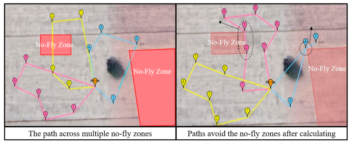
When the map features multiple forbidden navigation zones and the planned route passes through one of these zones, we used the A* search algorithm to plan a new route that avoided the forbidden area, as shown in Figure 16. The numbers are the order of visit, turning points (dash line circles) were added outside the multiple restricted navigation zones, thus avoiding them, and the path was re-planned to achieve a balanced route.
3.1.2. Swarming in Multiple No-Fly Zones (Single Route)
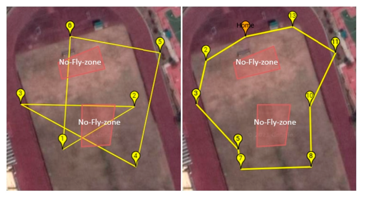
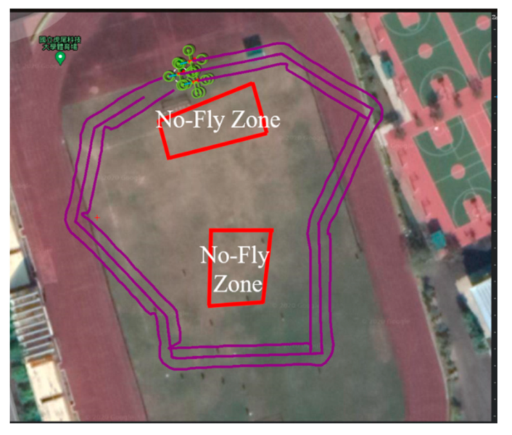
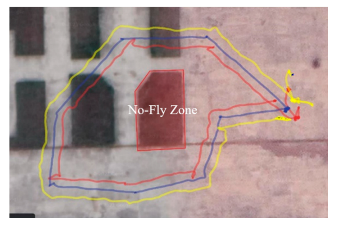
For the drone group, the forbidden area generates additional turning points depending on the radius of the group formation and the inclination angle of each side. The farthest point of the forbidden area is used as the turning point to ensure that the drone group successfully avoids passing through the forbidden zone while turning at various angles. First, we simulated the formation function and the effect of avoiding the restricted navigation zone. The left side of Figure 17 shows the pre-planning path, while the right side shows the path after planning. Figure 18 shows the simulated effect. The formation radius was 4 m, and the fleet successfully avoided the restricted area after running the algorithm. Following this successful simulation, the actual experiment used a different route. Figure 19 shows the experimental path of the fleet formation mission. The left side is the unplanned path, and the right side is the planned path. After the actual flight, we verified that individual and multiple drones can successfully avoid the restricted navigation area and that different paths will not cause path traversal problems. The experimental flight trajectory log is shown in Figure 20.
3.2. Dynamic Avoidance Test—Single UAV
Following the path planning algorithm test, to examine the whole D* Lite algorithm running on the edge computing system, a single UAV test was first performed to verify the avoidance effect under the dynamic path planning through actual flight performance.
3.2.1. Autonomous Flight Experiment
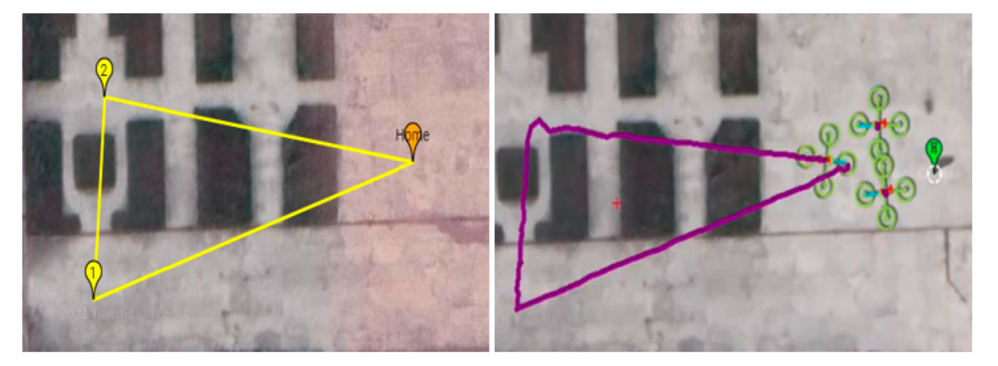
An actual flight experiment with a single UAV was conducted on 21 May 2021, at 10:21 a.m. in an open field in Yunlin County, Taiwan. The overall system performance was verified with a single UAV test with the experimental flight path and the flight trajectory monitored by the ground station, as shown in Figure 21. In the test, the single UAV successfully received the task from the ground control to complete the flight autonomously.
3.2.2. Simulation of the Dynamic Avoidance Effect
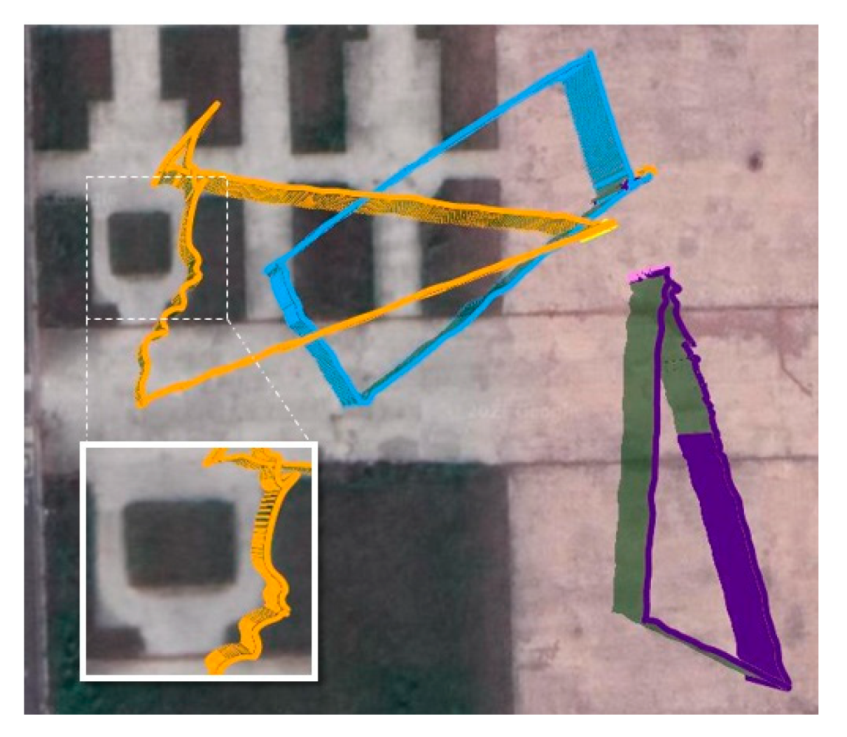
To test the performance of the multi-path dynamic programming algorithm, whole mission waypoints were divided into three paths by optimization algorithm, as A, B, and C routes shown in Figure 22 (left). The first test was to conduct a simulation test with a single UAV, which was assigned to execute B-route, and the obstacle information (position of the tree) was manually uploaded after the task was started to confirm whether the algorithm could avoid obstacles in real time. As shown in Figure 22 (right), the UAV on B-route smoothly avoided the trees and completed the remaining flight mission, thus providing initial validation of the dynamic avoidance algorithm.
3.3. Dynamic Avoidance Test—Three UAVs
Following the single UAV mission, flight mission verification was conducted for three drones. To reduce flight risk, the three-drone ground test was first performed using the software-in-the-loop (SIL) simulation to check whether the algorithm and every sub-system was functioning normally. The SIL simulation result showed that each drone perfectly flew on its optimized track. The successful three drones’ simulation results in multi-path programming, along with the aforementioned single UAV flight test for dynamic avoidance function, gave us the confidence to move to the full-scale flight validation. In the following sections, we compare the simulation and flight test results.
3.3.1. Autonomous Flight Mission Simulation (Including Immediate Avoidance)
As described in this section, full-system functional verification was achieved through one simulation and two experiments. The first experiment tested dynamic avoidance using three UAVs. In Figure 23, the green area in the left frame is an obstacle that is unknown at first, and the original yellow flight path intersects with the obstacle. However, the experimental results showed that once provided with the obstacle information, the drone will instantly act to avoid it. Once the obstacle is recognized as a restricted area, the flight route is re-planned in real time, allowing the drone to circumvent it. The first experiment took place during a strong wind, affecting drone stability and making it difficult to correct the course, as shown in Figure 24. Nevertheless, the flight trajectory log in Figure 24 still shows that the UAV successfully avoided the obstacles and completed the entire flight. Thus, the first experiment indicated the feasibility of immediate obstacle avoidance.
The second experiment was conducted at another site. As shown in Figure 25, the completed paths of each station were assigned to simulate the flight trajectory and avoidance effects. As shown in Figure 26 (left), the pink flight path shows the simulated UAV receiving location information for the trees, triggering two immediate turns to avoid them.
The experimental task route was the same as the group route planned during the simulation, as shown in Figure 25. The trees in the experimental field were also used as obstacles for real-time avoidance. In the experiment, while the outbound copter flew at a speed of 5 m/s, the experimenter suddenly triggered new obstacle information (tree) when the distance between copter and tree was less than 10 m, which said it had around 2 s to handle an avoidance act, including D* Lite rerouting and the vehicle’s avoidance maneuver. The experimental flight trajectory is presented as the log in Figure 26 (right). The yellow trajectory shows that the UAV successfully avoided the trees twice, thus verifying the effect of dynamic path planning through the mobile vehicle’s edge computing without any command from the central ground station. The computing time of first avoidance (outbound) for D* Lite path re-planning took about only 3.2 milliseconds to calculate. Since the first avoidance instance had already recorded the position of the obstacle, the calculation for the subsequent second avoidance (backbound) was 1.4 milliseconds, less than half that of the first instance, owing to having a shorter path to calculate. From the results, the calculation time of fewer than 4 milliseconds was quite effectively instantaneous, indicating an effective obstacle avoidance.
3.3.2. Simulation and Experimental Comparison
Since the simulation presented an ideal state, the flight trajectory of the UAV was quite smooth. By contrast, the real-world environment includes external factors, such as wind speed and wind direction, and GPS drift, which inevitably result in sloshing during flight and deviation from the planned route. Figure 27 compares the flight conditions of the entire system simulation and the experiment. In addition to the relative lack of flight path smoothness noted previously, a key difference is shown where the yellow experimental trajectory avoided the first tree on the opposite side of the simulation, while the second avoidance happened identically in both the simulation and experiment. This is because, in the experiment, the UAV judged that the distance required for avoidance was shorter from the other side based on its current position. Therefore, the dynamic planning algorithm was used to plan the avoidance routes.
4. Conclusions
This study improves existing path planning algorithms and incorporates the conditions of multiple restricted navigation zones and formation flying as considerations for restricted navigation zone avoidance during path planning. It also successfully designed a decentralized edge computing-based system architecture for group UAV guidance and control.
For drone mission execution, this study diverges from conventional ground control systems. Integrating the edge control system allows the drone to determine its current status and location, and then head to the target points. Integrating the D* Lite dynamic path planning algorithm allows for improved, real-time task path re-planning to avoid both known restricted areas and unexpected obstacles, allowing the drones to follow the most efficient path to safely reach all target points. The improved D* Lite dynamic programming algorithm developed in this study was experimentally validated to show its effectiveness in real-time obstacle avoidance.
Author Contributions
Conceptualization, M.-T.L.; Formal analysis, S.-T.K. and Y.-R.C.; Methodology, M.-T.L. and M.-L.C.; Project administration, M.-T.L.; Software, S.-T.K. and Y.-R.C.; Writing—original draft, S.-T.K. and Y.-R.C.; Writing—review & editing, M.-T.L. and M.-L.C. All authors have read and agreed to the published version of the manuscript.
Funding
This research was funded by the Ministry of Science and Technology of the Republic of China (Taiwan), grant number MOST 110-2221-E-150-004.
Institutional Review Board Statement
Not applicable.
Informed Consent Statement
Not applicable.
Data Availability Statement
Data sharing not applicable.
Conflicts of Interest
The authors declare no conflict of interest.
References
- Dull, Dirty, Dangerous Mission? Send in the Robot Vehicle. Available online: https://www.army.mil/article/154248/dull_dirty_dangerous_mission_send_in_the_robot_vehicle (accessed on 12 May 2018).
- Humphreys, C.J. Optimal Control of an Uninhabited Loyal Wingman; Department of the Air Force Air University: Austin, TX, USA, 2016. [Google Scholar]
- Yang, F.; Ji, X.; Yang, C.; Li, J.; Li, B. Search of UAV swarm based on improved ant colony algorithm in uncertain environment. In Proceedings of the 2017 IEEE International Conference on Unmanned Systems (ICUS), Beijing, China, 27–29 October 2017; pp. 231–236. [Google Scholar]
- Huang, W.S. Task Assignment of UAV Swarm with No-Fly Zone Avoidance. Master’s Thesis, Automation Engineering, National Formosa University, Yunlin, China, 2020. [Google Scholar]
- Lee, M.; Lai, Y.; Chuang, M.; Chen, B. Design and validation of a route planner for logistic UAV swarm. Intell. Autom. Soft Comput. 2021, 28, 227–240. [Google Scholar] [CrossRef]
- Ahmed, E.; Rehmani, M. Mobile Edge Computing: Opportunities, solutions, and challenges. Future Gener. Comput. Syst. 2017, 70, 59–63. [Google Scholar] [CrossRef]
- Zhou, F.; Hu, R.; Li, Z.; Wang, Y. Mobile Edge Computing in Unmanned Aerial Vehicle networks. IEEE Wirel. Commun. 2020, 27, 140–146. [Google Scholar] [CrossRef] [Green Version]
- Huang, P.; Wang, Y.; Wang, K. Energy-efficient Trajectory Planning for a Multi-UAV-assisted Mobile Edge Computing System. Front. Inf. Technol. Electron. Eng. 2020, 21, 1713–1725. [Google Scholar] [CrossRef]
- Ji, J.; Zhu, K.; Yi, C.Y.; Wang, R. Joint Task Offloading and Trajectory Optimization for Multi-UAV Assisted Mobile Edge Computing; Nanjing University of Aeronautics and Astronautics: Nanjing, China, 2021. [Google Scholar]
- What is Unmanned Aircraft Systems Traffic Management? Available online: https://www.nasa.gov/ames/utm (accessed on 29 May 2021).
- Koenig, S.; Likhachev, M. D* Lite; College of Computing, Georgia Institute of Technology: Atlanta, GA, USA, 2002. [Google Scholar]
- DroneKit-Python Library. Available online: https://github.com/dronekit/dronekit-python (accessed on 19 July 2020).
- MAVLink Developer Guide. Available online: https://mavlink.io/en/ (accessed on 22 June 2020).
- Chen, B.Y. Failure Robot Path Complementation for Robot Swarm Mission Planning. Master’s Thesis, Automation Engineering, National Formosa University, Yunlin, China, 2017. [Google Scholar]
- Wu, S.Y. Development of 4D Mission Programming for UAV Swarm. Master’s Thesis, Automation Engineering, National Formosa University, Yunlin, China, 2019. [Google Scholar]
- Lee, M.; Chen, B.; Lai, Y. A Hybrid Tabu Search and 2-opt Path Programming for Mission Route Planning of Multiple Robots under Range Limitations. Electronics 2020, 9, 534. [Google Scholar] [CrossRef] [Green Version]
- Civil Aviation Act (Taiwan). Available online: https://www.caa.gov.tw/ContentAndMorefiles.aspx?a=1309&lang=2 (accessed on 9 March 2021).
- Khalid, A.; Mansour, A.; Muhammad, E.; Hedjar, R.; Ebrahim, M. D* Lite Based Real-Time Multi-Agent Path Planning in Dynamic Environments. Int. J. Eng. Res. Appl. 2012, 2, 170–174. [Google Scholar]
- Luo, Z.; Zhang, Y.; Mu, L.; Huang, J.; Xin, J.; Liu, H.; Jiao, S.; Xie, G.; Yi, Y. A UAV Path Planning Algorithm Based on an Improved D* Lite Algorithm for Forest Firefighting. In Proceedings of the 2020 Chinese Automation Congress (CAC), Shanghai, China, 7–8 November 2020. [Google Scholar]
- MAVProxy. Available online: https://ardupilot.org/mavproxy/ (accessed on 14 October 2020).
- Mission Planner. Available online: https://ardupilot.org/planner/ (accessed on 14 October 2020).
- APM Planner 2. Available online: https://ardupilot.org/planner2/ (accessed on 14 October 2020).
- QGroundControl (QGC). Available online: http://qgroundcontrol.com/ (accessed on 1 April 2021).
Figure 1.
System flow chart.

Figure 2.
System schematic.

Figure 3.
Small ground station.

Figure 4.
Formation control flow chart.

Figure 5.
Communication format.

Figure 6.
Single-route solution.

Figure 7.
Multi-route solution.

Figure 8.
D* Lite algorithm flow chart.

Figure 9.
Comparison of drone movement methods.

Figure 10.
Modified D* Lite flow chart.

Figure 11.
Monitoring station.

Figure 12.
Prototype UAV.

Figure 13.
Calculation time of Python on PC and Jetson Xavier NX.

Figure 14.
Calculation time of Cython on PC and Jetson Xavier NX.

Figure 15.
Comparison of Python and Cython on Jetson Xavier NX.

Figure 16.
Before and after avoidance planning for multiple no-fly zones.

Figure 17.
Flight trajectory for formation flight simulation.

Figure 18.
Formation mission simulation results.

Figure 19.
Flight trajectory for the formation flight experiment.

Figure 20.
Formation flight experiment results.

Figure 21.
Planned path and UAV mission execution trajectory.

Figure 22.
Programmed group route (left) and real-time avoidance simulation (right).

Figure 23.
Route planning results of the first experiment.

Figure 24.
Flight trajectory log of the first experiment.

Figure 25.
Route following route planning and assignment.

Figure 26.
Multi-UAVs dynamic avoidance simulation (left) and real flight test trajectory (right).

Figure 27.
Comparison of simulated and experimental flight trajectories.


Table 1.
Experiment items.
| Items of Experiment | Items |
|---|---|
| Algorithm Benefit | a. Test of multiple no-fly zone avoidance (three routes) b. Test of swarming in multiple no-fly zones (single route) |
| Single Drone | a. Autonomous flight b. Dynamic avoidance simulation |
| Three Drones | a. Autonomous flight simulation (including immediate avoidance) b. Comparison of simulation and experimental results |
Publisher’s Note: MDPI stays neutral with regard to jurisdictional claims in published maps and institutional affiliations. |
© 2022 by the authors. Licensee MDPI, Basel, Switzerland. This article is an open access article distributed under the terms and conditions of the Creative Commons Attribution (CC BY) license (https://creativecommons.org/licenses/by/4.0/).
Share and Cite
MDPI and ACS Style
Lee, M.-T.; Chuang, M.-L.; Kuo, S.-T.; Chen, Y.-R. UAV Swarm Real-Time Rerouting by Edge Computing D* Lite Algorithm. Appl. Sci. 2022, 12, 1056. https://doi.org/10.3390/app12031056
AMA Style
Lee M-T, Chuang M-L, Kuo S-T, Chen Y-R. UAV Swarm Real-Time Rerouting by Edge Computing D* Lite Algorithm. Applied Sciences. 2022; 12(3):1056. https://doi.org/10.3390/app12031056
Chicago/Turabian StyleLee, Meng-Tse, Ming-Lung Chuang, Sih-Tse Kuo, and Yan-Ru Chen. 2022. "UAV Swarm Real-Time Rerouting by Edge Computing D* Lite Algorithm" Applied Sciences 12, no. 3: 1056. https://doi.org/10.3390/app12031056
Note that from the first issue of 2016, this journal uses article numbers instead of page numbers. See further details here.