
Influence of Circular Saw Blade Design on Reducing Energy Consumption of a Circular Saw in the Cutting Process

Department of Manufacturing and Automation Technology, Faculty of Technology, Technical University in Zvolen, 960 01 Zvolen, Slovakia
*
Author to whom correspondence should be addressed.
Appl. Sci. 2022, 12(3), 1276; https://doi.org/10.3390/app12031276
Submission received: 21 December 2021
/
Revised: 17 January 2022
/
Accepted: 21 January 2022
/
Published: 25 January 2022
(This article belongs to the Topic Industrial Engineering and Management)
Abstract
:Optimal cutting conditions, which lead to a high quality of the machined surface and low energy consumption, are crucial for wood processing. This paper describes the effect of feed speed, cutting speed and mean chip thickness on energy consumption and saw blade surface temperature during the spruce (Picea excelsa) cutting process. In the experiment, the energy consumption and the surface temperature of the saw blades were measured to find the optimal cutting conditions for the energy-efficient cutting process. The surface temperature of the circular saw blade was monitored online using a non-contact infrared sensor connected directly to a PC via a USB connector. The results show that the cutting power and the surface temperature of the circular saw blade increased with increasing feed speed. The lowest values of cutting power were shown by the saw blade CSB3. Compared to the classic CSB1 circular saw blade, the values were lower by 8%. The surface temperature of the circular saw blade is highest at the outer edge (area of the heel of the teeth), and decreases towards the center of the circular saw blade. For an identical mean chip thickness, energy-efficient cutting was achieved at a feed speed of 21 m/min. There must be a trade-off between machine productivity and energy consumption. Monitoring the cutting process of circular saws using intelligent sensors is the way to adaptive control systems that ensure higher quality of the machined surface and cost-effective machining.
1. Introduction
Circular saws are the most used machines in the primary and secondary industries of processing wood and wood materials. They are intended for transverse cutting (cutting in the direction perpendicular to the fibers) and slitting (cutting in the direction of the wood fibers). They occur mainly in sawmills, resawings, or in workshops to produce wood products as secondary equipment that cut and treat wood. They are mostly edging saws, ripcut circular saws, multi-blade ripsaws, multi-blade cross-cut circular saws, parallel pendulum saws, sliding table saws, and CNC panel saws [1]. Transverse cutting operations are divided into two types: transverse cutting to the preliminary dimension and transverse cutting to the final dimension [2]. When using forest wood resources, cross-cutting to a preliminary dimension is often used, such as cutting a tree for logs and production of various wood products. Research on reducing energy consumption in wood processing machines is carried out by introducing innovations in cutting mechanisms [3,4,5], drives [6,7,8], or control system. The authors of [9] reported that lower values of cutting power were measured in transverse cutting of balks of coniferous (Spruce) than in deciduous wood (Beech). The rake angle (−5°; 0°; 20°) has a great influence on the cutting power. The lowest values of cutting power were achieved at different feed rates for the rake angle of 20°. The authors of [10] also reported the different influence of coniferous (Spruce) and deciduous wood (Beech and Oak) on the cutting power in cross-cutting of boards.
Thus far, little attention has been paid to the research of the cutting process in primary applications of wood processing (lumber production). Optimal woodworking in terms of energy efficiency and high cutting accuracy (waviness of the machined surface) plays an important role in cost-effective lumber production and investment in technical development. Energy consumption and waviness increase with increasing feed speed and cutting height [11,12]. Among several monitored parameters, the thickness of the chip and the cutting direction have the greatest influence on the main cutting force. Other parameters, such as wood density, wood moisture, and cutting wedge rake angle, had a lower effect. Most of the research on the cutting process is focused on secondary applications of wood processing (production of wood products). Research of optimal woodworking conditions [13,14] has shown that the cutting process is influenced by three basic factors: type of wood, technical equipment, and coefficient of wood moisture. The process of sawing wood is influenced by specific properties of the workpiece (material—hard or soft wood, agglomerated materials DDT, MDF, or plywood, moisture, density, temperature, etc.), circular saw blade (rake angle γ, clearance angle α, cutting wedge angle β, cutting speed vc, etc.), feed (feed speed vf, cutting height H, overlap f, etc.), and a combination of factors. The effect of these factors has been investigated on energy consumption by the authors of [15,16,17,18,19,20,21,22,23]. When using circular saws, the waviness of the machined surface is affected by cutting parameters such as cutting height and feed speed. Other factors that affect the waviness of the machined surface are the dynamic behavior, oscillation, and deflection of the saw blade from the cutting plane [1]. Research of the effect of vibration and deflection of the circular saw blade on the waviness of the machined surface has not yet been sufficiently carried out except for a few works [11,24,25,26,27,28]. One of the factors that influences the oscillation and deflection of the saw blade is its heating in the tooth part during the cutting process. The most significant obstruction during cutting is its aberration (deformation) in a plane [29]. The effect is only caused by compressive stress in the circular saw blade, which is dependent on the temperature distribution. Knowing the accurate temperature distribution is one of the main points to solve the problem. The measurement of the tool surface temperature during a high cutting speed (vc = 50–100 m/s) is not easy. The thermocouple method (copper–constantan) with a diameter wire of 0.125–0.15 mm was used [30,31,32]. The measuring of the temperature of the circular saw blade body with the infrared thermometer is published by authors [33,34,35,36,37,38,39,40,41]. The simulation of the temperature cutting process by means of a digital computer was used in [42].
Optimal machining of wood and wood materials is a multi-parameter problem when low energy consumption, low noise emission, and low dust emission are required versus high cutting accuracy, tool life, and high productivity of the cutting process. The main goal of this article is to determine the influence of the circular saw blade design on the energy consumption of the circular saw. The range of the monitored feed and cutting speeds was designed to suit extreme cutting conditions in secondary wood processing. The influence of cutting parameters on the energy consumption and the heating temperature of the circular saw blade was investigated.
2. Materials and Methods
Samples of spruce wood (Picea excelsa) with dimensions of 1500 × 300 × 25 mm (L × W × H) were used in the experiment. They were cut into boards and then processed to the exact thickness of 25 mm by one-sided thicknessing planer. The measurement of the moisture content was performed with a Greisinger electronic device type GHH 91 (Figure 1). The average moisture content of samples was 7% with a standard deviation of 0.3%.
For the experiment, three saw blades with cemented carbide cutting plates for wood machining (Stelit s.r.o Trenčín, Slovak republic) were used as tools. The material of the body circular saw blades was the steel (DIN 75Cr1, EN 1.2003). Teeth of circular saw blades are fitted with inserts of cemented carbide and are alternately diagonally grinded. The structural differences of the circular saw blades are shown in Figure 2. Circular saw blades (CSB) were different in the width of the cutting plates and in the surface treatment. CSB1 had an uneven tooth spacing, cemented carbide cutting plates were soldered on its teeth, and it had no surface treatment. It had radial and compensating slots, which are terminated by holes and filled with copper threads (Figure 2a). CSB2 differed from CSB1 only in the width of the plates ST = 3.8 mm (Figure 2b). CSB3 as well as CSB1 had an uneven tooth spacing, radial and compensating slots in the body, which are terminated with holes and filled with copper threads, and surface treatment. The surface of the CSB3 was altered powder coating RAL 9006 (Tiger LACQUER SLOVAKIA Ltd., Pezinok, Slovakia). It was coated in the company K-system Ltd. (Kosorín, Slovakia) from both sides with a thickness of 100 µm and fired in a kiln at a time of 20 min at a temperature of 192 °C (Figure 2c).
The basic parameters of the used circular saw blades for experimental measuring are in Table 1.
A full factorial experimental design resulted in nine different machining conditions (Table 2). The experiment was conducted with six replicates for each treatment.
The average chip thickness in orthogonal cutting and parallel to the fiber direction with a circular saw blade (Figure 3) is defined according to [1]:
where tchip is the average chip thickness (mm), vf is the feed speed (m/min), vc is the rotation speed (rev/min), z is the number of teeth, D is the tool diameter (mm), H is the cutting height (mm), and f is the override (mm).
The whole experiment was carried out on an experimental single-shaft circular saw, which is located in the laboratory of the KVAT Faculty of Technology in the development workshops of the Technical University in Zvolen. The main purpose of using this machine is the production of wood semi-finished products and experimental research. The machine is of a compact construction; the main supporting part of the whole machine is a frame, which is welded from a plate steel material. The circular saw-cutting mechanism assembly is attached to the frame by screw connections. The high-speed part of the cutting mechanism (shaft) is mounted in radial ball bearings in the bearing housings. The feeding mechanism of the circular saw consists of a belt conveyor and an upper roller feeder MW 102 (TOS Svitavy a. s., Czech Republic). The feed speed of the belt conveyor is continuously variable in the range of (4–40) m/min. The feed speed of the upper roller feeder is gradually variable by means of a gearbox in the range of (4–34) m/min. The moving parts of the machine are mounted in plain bushes or ball bearings. The drive of the circular saw shaft is ensured by an electric motor, pulleys, and V-belts. The electric motor has a power of 5.5 kW and speed of 2910 rev/min. A smooth change of shaft speed is ensured by using a frequency converter (VONSCH s.r.o Brezno, Slovakia). The circular saw was connected to a mobile sawdust extractor type U 1500.
The power measurement was realized by the frequency converter, while the active power input without losses and the power of the electric motor were evaluated from the current, voltage, and efficiency of the electric motor. Recording of measured power quantities could be read, displayed, and saved on an external computer via VDS software (Vonsch Drive Studio, Brezno, Slovakia). This measuring device generated 20 power values per second. Individual cuttings of the samples lasted more than 3 s. All measurements have already considered the values during idling before and after cutting.
Cutting power is calculated based on the relationship:
where PC is total power during sawing (W) and PC0 is power during idling (W), calculated as:
and:
where UC and UC0 are voltages during sawing and idling (V), IC and IC0 are currents during sawing and idling (A), and cosφ is the power factor.
The temperature distribution in the circular saw blade is determined by the following factors: friction in the cutting process and heat dissipation from the saw blade surface. The differential equation determining the temperature distribution is given by the expression:
The terms in the Equation (5) are as follows:
where λ is the thermal conductivity of steel (W/m/K) (for steel = 50), a is the thickness of the circular saw blade (m), τ is time (sec), r is the radius of the circular saw blade (m), c is the specific heat (J/kg/K) (for steel ≈ 469), ρ is the density (kg/m3) (for steel ≈ 7800), α is the coefficient of heat transfer (W·m2/K) (for air 10–500), κ is the thermal diffusivity (m2/h) (for circular saw blade steel ≈ 0.049), Q1 is the quantity of heat generated at the unit surface area by friction in time unit, Φ is the temperature difference between T and T0 on a certain place, T is the temperature of this place (K), and T0 is the temperature of the air (K).
For measuring the temperature, Pixsys/Calex PUA8-CF sensors were used. They are industrial infrared contactless temperature sensors with standardized current output and USB connection. It is possible to set values such as measuring range corresponding to analog output, emissivity, etc. The sensor works with a connected analog output (powered by a Pixsys power terminal) or with a connected USB, or with both outputs connected. The parameters of the temperature sensor are given in Table 3.
The infrared thermometer uses the law of Stefan–Boltzmann for the temperature calculation (Lévesque 2014), which is given by the equation:
where I is the heat energy (W/m2), ε is the emissivity, σ is the Stefan–Boltzmann constant (W/m2/K4) (5.6703·10−8), T is the temperature of the measured body (K), and T0 is the surrounding temperature (K).
3. Results and Discussion
The measured values of the power input of the circular saw electric motor, as well as the values of saw blades surface temperature, were pre-processed in the program Excel. The values of the cutting power were further processed in the program Statistics 12. The figures showing the dependence of the cutting power on the individual parameters show the mean values from six repeated measurements. The figures showing the dependence of the surface temperature of the saw blades on the individual parameters show the mean values from two repeated measurements.
3.1. Consumption of the Cutting Power
The results of the processing of the cutting power values in the program Statistica 12 are given in Table 4.
The Statistics 12 program shows that all considered cutting factors have a significant effect on the consumption of cutting power at a significance level of 0.95. More precisely, the design of the circular saw blade, the feed speed as well as the rotation speed affect the value of the cutting power. According to Statistica 12, the feed speed was the factor that had the greatest impact on cutting performance. Rotation speed was the second most important factor influencing the cutting power. Figure 4 shows the effect of the feed speed and circular saw blade design on the cutting power. Increasing the feed speed from 14 to 21 m/min significantly reduced the cutting power by 10%. Increasing the feed speed from 21 to 28 m/min significantly increased the cutting power by 39%. Similar results were reported by the authors of [11]. The modified design of the CSB3 circular saw blade compared to the classic (unmodified) design of the CSB1 circular saw blade reduced the cutting power values of 8.0%.
Figure 5 shows the effect of the cutting speed and circular saw blade design on the cutting power. The figure shows that the cutting power increases with an increasing feed speed for all circular saw blade designs at the feed speed used. The increase of speed within range of (4050–4150) rev/min caused an increase in cutting power of 11%. However, this finding contradicts [22], where the problem is discussed that a higher cutting speed can reduce the cutting power. The authors justified this by the fact that there is a reduction in the tool-workpiece friction and changes in lignin in the cut area. Some other scientists [12,14] stated in their work that the cutting speed did not have a significant effect on the cutting power. These conclusions correspond well with the results obtained in our experimental measurements.
The critical factor in the sawing process on a circular saw is the average chip thickness. It has a significant effect on cutting power and dust emissions. Figure 6 shows the effect of the mean chip thickness and circular saw blade design on the cutting power.
From Figure 7, the circular saw blades CSB1, CSB2, and CSB3 had the lowest cutting power at a mean chip thickness of 0.097 mm, which corresponded to a feed speed of 21 m/min. The cutting power increased with decreasing mean chip thickness up to 0.063 mm, which corresponded to a feed speed of 14 m/min. The authors of [15,21] also mentioned this important phenomenon in their works. The highest cutting power of all three circular saw blades was measured at a mean chip thickness of 0.13 mm, which corresponded to a feed speed of 28 m/min. The cutting power generally increases with increasing mean chip thickness from a certain value, which depends on the cutting parameters. The results of our experimental measurements are consistent with [12,16,18]. The cutting power values were different for each circular saw blade, the lowest values had CSB3, slightly higher values CSB2, and the highest values CSB3.
3.2. Circular Saw Blade Surface Temperature
The adverse effect of the heating of the circular saw blade in the cutting zone and, thus, the resulting temperature difference between the central hole and the edge of the circular saw blade caused increasing variability in the cutting process [31]. The author of [36] also emphasized that the temperature differences of the circular saw blade between the edge and the center hole have a fundamental effect on its rigidity. Therefore, it is necessary to measure the temperature of the circular saw blade both at the tim, in the middle of the radius, and at the center hole. This demonstrates the heating and cooling principles of the circular saw blade. For experimental measurements of the surface temperature of circular saw blades, the non-contact method was used by means of an infrared sensor Calex PUA8-CF. The temperature sensor was set to three positions relative to the center of the circular saw blade, as shown in Figure 8. When changing the cutting parameters, we obtained 54 data files for each circular saw blade. From the temperature values obtained under the same cutting conditions, we calculated the arithmetic mean.
1—frequency converter (UNIFREM 400 007 M), 2—sine filter (SKY3FSM25), 3—control panel with digital display connected to the frequency converter via the RS232C serial interface, 4—electric motor, 5—V-belt transmission, 6—frame circular saw with a shaft mounted in radial bearings, 7—saw blade with clamping flanges, 8—three positions of the Calex PUA8-CF temperature sensor, 9—laptop.
Figure 9 shows the temperature change during one cutting cycle. The terms ΔTE, ΔTM, and ΔTR represent the maximum values of the saw blade temperature at the center hole, at the center of the radius, and at the edge after cutting process. The symbol Δt is defined as the time required to reach the temperature of the circular saw blade after the cut to a constant value.
Figure 10 shows the dependence of the surface temperature of the circular saw blades on the feed speed at a shaft speed of 4050 rev/min.
As we can see from Figure 10, the surface temperatures of the circular saw blades CSB1 and CSB2 had values at about 21 ± 0.5 °C at the sensor position of 65 mm from the shaft axis (near the flanges). These temperatures increased slightly with increasing feed speed to values of 23–24 °C. Based on experimental measurements, the authors of [30,40,41] reported similar temperature values in the range of 22–24 °C for the area of clamping flanges. At the position of the temperature sensor of 110 mm from the shaft axis, the surface temperatures of the discs have already increased significantly to values of 24–25 °C. These temperatures also changed with increasing feed speed. At the last position of the sensor closest to the heel circle of the teeth (R = 155 mm) from the shaft axis, the surface temperature of the discs reached 32–34 °C. The authors of [35] stated a temperature value of 33 °C for the area of the heel circle of teeth. This area of the circular saw blades was most affected by the change in feed speed of all three areas. The temperature gradient created at CSB2 is 41–32 °C, and 42.6–34 °C at CSB1. The circular saw blade CSB3, which had a powder-coated coating applied to the surface, differed significantly in temperature from CSB1 and CSB2, mainly in the area (R = 155 mm). The highest temperature gradient between the areas (R = 155 mm and R = 65 mm) is at a feed speed of 28 m/min for all circular saw blades. For CSB1 this value is 18.9 °C and for CSB2, it is 17.6 °C. Comparing the temperature gradient for CSB3 (3.1 °C), there is a big difference between CSB1 and CSB2. This difference in temperature gradient may be one of the parameters that causes the different dynamic behaviors of CSB3.
In Figure 11, we can observe the dependence of the temperature on the surface of the circular saw blades from the distance of the temperature sensor from the axis of the saw blades (shaft) at a speed of 4100 rev/min.
Comparison of Figure 10 (a) CSB1, (b) CSB2, and (c) CSB3 in terms of the temperatures at individual positions of the sensor at a shaft speed of 4100 rev/min showed a large temperature difference between circular saw blades CSB1 and CSB2 and circular saw blade CSB3 on the sensor position 155 mm from the shaft axis. As we can see in Figure 10a,b, CSB2 had lower temperature values than CSB1 at each feed speed (0.7–1.5) °C. This temperature difference can be explained by the shorter cutting edge length of l = 0.2 mm at CSB2. At the temperature sensor distance of 100 mm from the shaft axis, CSB1 and CSB2 had almost identical results. The same applies for the temperature sensor distance of 65 mm from the shaft axis. For CSB1 and CSB2, there is a large temperature gradient between the 155 mm and 110 mm positions. From Figure 10, we see that the temperature gradient between the sensor positions 155 mm and 65 mm is not uniform; it has most likely an exponential dependence. When comparing all three circular saw blades, the course of the temperature gradient is similar, but the CSB3 differs in the lower temperature values at each position of the sensor.
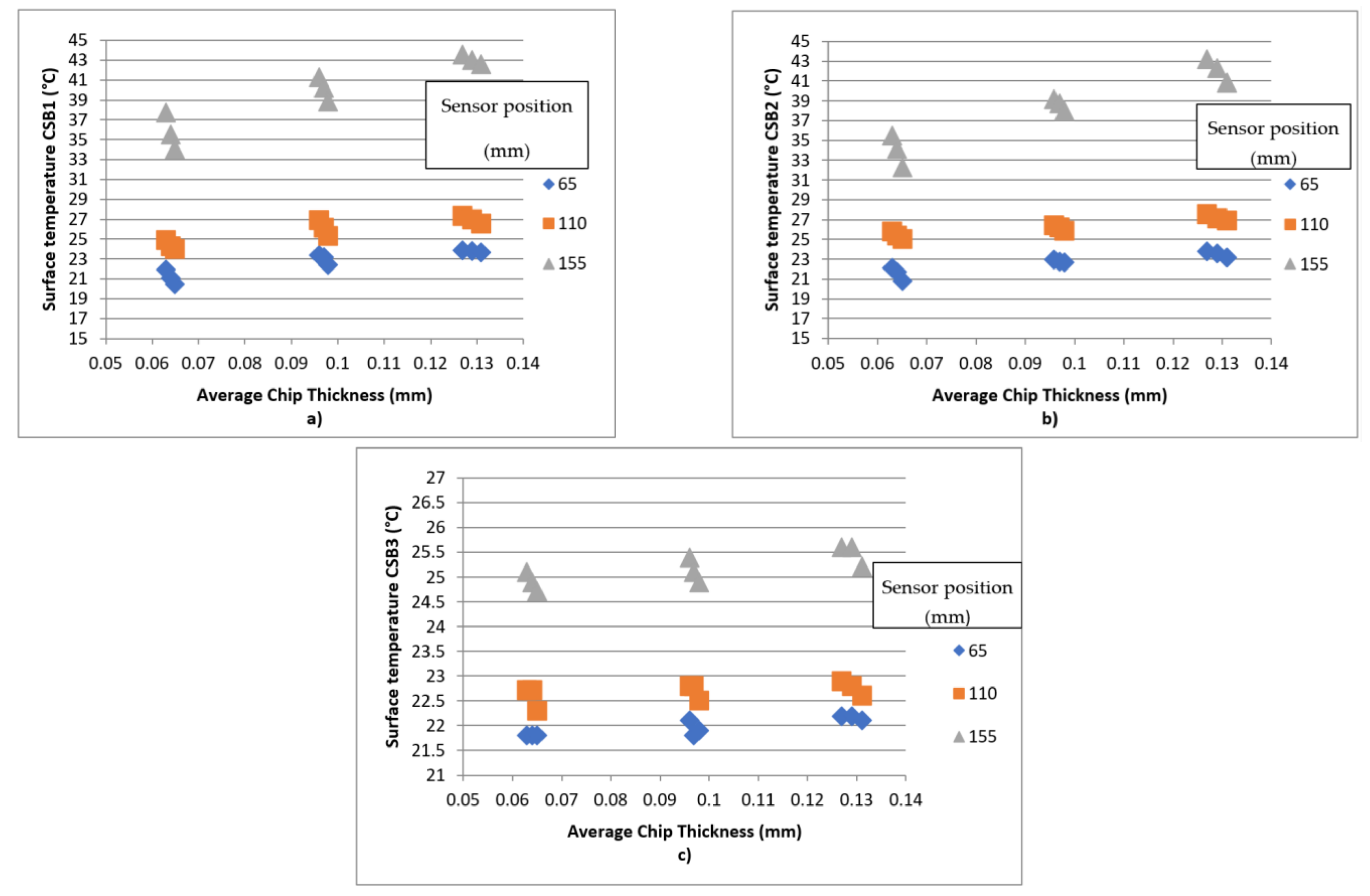
In Figure 11 (a) CSB1, (b) CSB2, and (c) CSB3, we can see the dependence of the surface temperature of the circular saw blades on the average chip thickness, at the three positions of the temperature sensor. At a feed speed of 14 m/min, which corresponded to a value of the mean chip thickness in the range of (0.063–0.065) mm, the temperature slowly increased with decreasing mean chip thickness for all three positions of the temperature sensor. We noticed a similar phenomenon in the dependence of the cutting power values on the mean chip thickness. Based on these results, we can say that the values of cutting power as well as the surface temperature of the circular saw blade are significantly influenced by the parameters of the cutting process. At feed speeds of (21–28) m/min, this phenomenon was repeated.
4. Conclusions
This paper assesses the effect of the feed speed, cutting speed, tool construction, and mean chip thickness on the cutting power and circular saw blade surface temperature during the spruce (Picea excelsa) cutting on an experimental single-shaft circular saw. The main goal of the research was to achieve sustainable (acceptable) woodworking with the lowest energy consumption. Emphasis was placed on performing experiments under cutting conditions that occur in the secondary wood processing industry, to better study the harsh cutting conditions. In addition, the surface temperature of the circular saw blades was measured, which is a significant factor influencing the dynamic behavior of the saw blade in the cutting process. The role of the mean chip thickness in the cutting process, which represents the combined effect of several cutting factors as a critical factor, was also investigated. Future research should focus on extending the experiment to a wood cutting process with a higher moisture content (raw wood).
The influence of the feed speed on the cutting power was in accordance with the data reported in the literature by several authors. Based on the measurement results, the value of the cutting power decreased in the feed speed range of (14–21) m/min. In the feed speed range of (21–28) m/min, the value of the cutting power increased. These data show that the lowest value of the cutting power at the given cutting parameters was achieved at a feed speed of 21 m/min for all circular saw blade designs and cutting speeds. Regarding the role of the circular saw blade design, we can see that the lowest value of the cutting power at the given feed speed was shown by the circular saw blade CSB3. Compared to the classic (unmodified) circular saw blade (CSB1), it showed cutting power values that were 8% lower.
The influence of the feed speed on the values of the circular saw blade surface temperature confirmed the dependences which are presented in scientific articles by several authors. As can be seen from the measurement results, the circular saw blade surface temperature increases the most at the edge of the circular saw blade depending on the feed speed. The maximum temperature difference for uncoated CSB1 and CSB2 circular saw blades is T = 8.5 °C. The temperature difference of 3 °C was in the middle of the radius of these circular saw blades and a difference of °C was around the flanges. The temperature difference at the coated (modified) CSB3 circular saw blade is T = 0.5 °C at all three positions of the temperature sensor. The course of the surface temperature of the circular saw blades has an assumed exponential course from the edge to the area of the flanges. The individual circular saw blades differ from each other only in the size of the temperature drop. For the CSB1 circular saw blade, the temperature drop was ΔT = 18.9 °C; for the CSB3 circular saw blade, it was ΔT = 3.1 °C. This large difference in the temperature gradient of the two circular saw blades is probably the reason for the change in the dynamic behavior of CSB3 in the cutting process, which was finally reflected in its lowest values of cutting power.
The influence of the size of the average chip thickness on the values of the cutting power and the surface temperature of the circular saw blades is evident from Figure 7 and Figure 11. With an increasing value of the mean chip thickness in the range of 0.063–0.098 mm, the cutting power in the cutting process decreases for all three saw blades. In contrast, in the range of the mean chip thickness of 0.098–0.131 mm, the cutting power in the cutting process increases for all three circular saw blades. Under the given cutting conditions, all three circular saw blades showed the lowest values of cutting power at a mean chip thickness value of 0.01 mm. With a decreasing mean chip thickness value due to a change in cutting speed in the range of 0.063–0.065 mm, the surface temperature of the circular saw blades during the cutting process increases at all temperature sensor positions. The same applies to the ranges of 0.096–0.098 mm and 0.127–0.131 mm. With an increasing mean chip thickness value in the range of 0.065–0.131 mm, the surface temperature of the circular saw blades in the cutting process increases at all temperature sensor positions.
Author Contributions
Conceptualization, J.S. and Ľ.N.; methodology, J.S. and Š.B.; software Ľ.N. and P.K.; validation, J.S. and Ľ.N.; formal analysis, J.S., Ľ.N. and P.K.; investigation, J.S., Ľ.N. and Š.S.; resources, J.S.; data curation, J.S., Ľ.N. and P.K.; writing-original draft preparation, J.S. and Ľ.N.; writing—review and editing, P.K. and J.S.; visualization, J.S., Ľ.N. and P.K.; funding acquisition, Š.B. and P.K. All authors have read and agreed to the published version of the manuscript.
Funding
This research was funded by FMA analysis of potential signals suitable for adaptive control of nesting strategies for milling wood-based agglomerates, grand number APVV-20-0403, supported by the Slovak Research and Development Agency, and by Progressive Research into Utility Properties of Materials and Products Based on Wood (LignoPro), grand number ITMS 313011T720, supported by the Operational Programme Integrated Infrastructure (OPII), funded by the ERDF.
Institutional Review Board Statement
Not applicable.
Informed Consent Statement
Not applicable.
Data Availability Statement
The data presented in this study are available on request from the corresponding author.
Conflicts of Interest
The authors declare no conflict of interest.
References
- Nasir, V.; Cool, J. A review on wood machining: Characterization, optimization, and monitoring of the sawing process. Wood Mater. Sci. Eng. 2020, 15, 1–16. [Google Scholar] [CrossRef]
- Sandak, J.; Negri, M. Wood surface roughness—What is it? In Proceedings of the 17th International Wood Machining Seminar (IWMS 17), Rosenheim, Germany, 26–28 September 2005; pp. 242–250. [Google Scholar]
- Spinelli, R.; Cavallo, E.; Eliasson, L.; Facello, A.; Magagnotti, N. The effect of drum design on chipper performance. Renew. Energy 2015, 81, 57–61. [Google Scholar] [CrossRef]
- Warguła, Ł.; Kukla, M.; Wieczorek, B.; Krawiec, P. Energy consumption of the wood size reduction processes with employment of a low-power machines with various cutting mechanisms. Renew. Energy 2022, 181, 630–639. [Google Scholar] [CrossRef]
- Gao, Y.; Kang, F.; Kan, J.; Wang, Y.; Tong, S. Analysis and experiment of cutting mechanical parameters for Caragana korshinskii (CK) branches. Forests 2021, 12, 1359. [Google Scholar] [CrossRef]
- Warguła, Ł.; Kukla, M.; Lijewski, P.; Dobrzyński, M.; Markiewicz, F. Influence of innovative woodchipper speed control systems on exhaust gas emissions and fuel consumption in urban areas. Energies 2020, 13, 3330. [Google Scholar] [CrossRef]
- Mergl, V.; Pandur, Z.; Klepárník, J.; Kopseak, H.; Bačić, M.; Šušnjar, M. Technical solutions of forest machine hybridization. Energies 2021, 14, 2793. [Google Scholar] [CrossRef]
- Lajunen, A.; Suomela, J.; Pippuri, J.; Tammi, K.; Lehmuspelto, T.; Sainio, P. Electric and hybrid electric non-road mobile machinery–present situation and future trends. World Electr. Veh. J. 2016, 8, 172–183. [Google Scholar] [CrossRef] [Green Version]
- Krilek, J.; Kováč, J.; Kučera, M. Wood crosscutting process analysis for circular saws. BioResources 2014, 9, 1417–1429. [Google Scholar] [CrossRef]
- Kminiak, R.; Kubš, J. Cutting power during cross-cutting of selected wood species with a circular saw. BioResources 2016, 11, 10528–10539. [Google Scholar] [CrossRef] [Green Version]
- Nasir, V.; Cool, J. Optimal power consumption and surface quality in the circular sawing process of Douglas-fir wood. Eur. J. Wood Wood Prod. 2019, 77, 609–617. [Google Scholar] [CrossRef]
- Cristóvăo, L.; Broman, O.; Grönlund, A.; Ekevad, M.; Sitoe, R. Main cutting force models for two species of tropical wood. Wood Mat. Sci. Eng. 2012, 7, 143–149. [Google Scholar] [CrossRef]
- Eyma, F.; Méausoone, P.; Larricq, P.; Marchal, R. Utilization of a dynamometric pendulum to estimate cutting forces involved during routing. Comparison with actual calculated values. Ann. For. Sci. 2005, 62, 441–447. [Google Scholar] [CrossRef]
- Méausoone, P.J. Choice of optimal cutting conditions in wood machining using the coupled tool-material method. In Proceedings of the 15th International Wood Machining Seminar, Los Angeles, CA, USA, 30 July–1 August 2001; pp. 37–47. [Google Scholar]
- Kivimaa, E. Cutting force in woodworking. In The State Institute for Technical Research; Publication No.18 Helsinki; VTT Technical Research Centre of Finland: Helsinki, Finland, 1950. [Google Scholar]
- Axelsson, B.O.; Lundberg, A.S.; Grönlund, J.A. Studies of the main cutting force at and near a cutting edge. Eur. J. Wood Prod. 1993, 51, 43–48. [Google Scholar] [CrossRef]
- Aguilera, A.; Méausoone, P.J.; Martin, P. Wood material influence in routing operations: The MDF case. Holz Roh-Werkst. 2000, 58, 278–283. [Google Scholar] [CrossRef]
- Vazquez-Cooz, I.; Meyer, R.W. Cutting forces for tension and normal wood of maple. For. Prod. J. 2006, 56, 26–34. [Google Scholar]
- Hlásková, L.; Orlowski, K.; Kopecký, Z.; Sviták, M.; Ochrymiuk, T. Fracture toughness and shear yield strength determination for two selected species of central European provenance. BioResources 2018, 13, 6171–6186. [Google Scholar] [CrossRef]
- Orlowski, K.A.; Ochrymiuk, T.; Atkins, A.; Chuchala, D. Application of fracture mechanics for energetic effects predictions while wood sawing. Wood Sci. Technol. 2013, 47, 949–963. [Google Scholar] [CrossRef] [Green Version]
- Aguilera, A. Cutting energy and surface roughness in medium density fiberboard rip sawing. Eur J. Wood Prod. 2011, 69, 11–18. [Google Scholar] [CrossRef]
- Naylor, A.; Hackney, P.; Clahr, E. Machining of wood using a rip tooth: Effects of workpiece variations on cutting mechanics. In Proceedings of the 20th International Wood Machining Seminar, Skellefteå, Sweden, 7–10 June 2011. [Google Scholar]
- Moradpour, P.; Scholz, F.; Doosthoseini, K.; Tarmian, A. Measurement of wood cutting forces during bandsawing using piezoelectric dynamometer. Drvna Ind. 2016, 67, 79–84. [Google Scholar] [CrossRef] [Green Version]
- Hutton, S.G.; Lee, V.; Kirbach, E. Effect of tooth front bevel angle on cutting accuracy and chip formation for circular rip saws. Holz Roh-Werkst. 1992, 50, 313–316. [Google Scholar] [CrossRef]
- Li, L.; Xi, B.T.; Yang, Y.F. Transverse deflection of circular saw and sawing profile on workpiece. J. Beijing For. Univ. 2007, 29, 141–145. [Google Scholar]
- Orlowski, K.A.; Sandak, J.; Tanaka, C. The critical rotational speed of circulr saw: Simple measurement method and its practical implementations. J. Wood Sci. 2007, 53, 388–393. [Google Scholar] [CrossRef]
- Ukvalbergiene, K.; Vobolis, J. Research of inter-impact of wood circular saws vibration modes. Wood Res. 2007, 52, 89–100. [Google Scholar]
- Pohl, M.; Rose, M. Piezoelectric shunt damping of a circular saw blade with autonomous power supply for noise and vibration reduction. J. Sound Vib. 2016, 361, 20–31. [Google Scholar] [CrossRef]
- Kopecký, Z.; Rousek, M. Impact of dominant vibrations on noise level of dimension circular saw blades. Wood Res. 2012, 57, 151–160. [Google Scholar]
- Konov, V.N. Research of the temperature field on the circular saw blades in the wood cutting process. In Working Machines, Tools in Machining of the Wood; University Textbook of the Scientific Works: Leningrad, Russia, 1982; Volume 9, pp. 3–6. [Google Scholar]
- Danielson, J.D.; Schajer, G.S. Saw blade heating and vibration behavior in a circular gang edger. In Proceedings of the Saw Tech 93—3rd International Conference on Sawing Technology, San Francisco, CA, USA, 14–16 October 1993. [Google Scholar]
- Ratnasingam, J.; Pew Ma, T.; Ramasamy, G. Tool temperature and cutting forces during the machining of particleboard and solid wood. J. Appl. Sci. 2010, 10, 2881–2886. [Google Scholar] [CrossRef] [Green Version]
- Mote, C.D.; Rahimi, A. Real time vibration control of rotating circular plates by temperature control and system identification. J. Dyn. Syst. Meas. Control. 1984, 106, 123–128. [Google Scholar] [CrossRef]
- Li, L.; Xi, B.T.; Yang, Y.F. Thermal and rotary stresses in circular saw blades. J. Beijing For. Univ. 2002, 24, 14–17. [Google Scholar]
- Sheikh-Ahmad, J.Y.; Lewandowski, C.M.; Stewart, J.S. Experimental and numerical methods for determing temperature distribution in a wood cutting tool. Exp. Heat Transf. 2003, 16, 255–271. [Google Scholar] [CrossRef]
- Lehmann, B. Heating and cooling of circular saws. In Proceedings of the Volume I—Oral Presentations of the 18th International Wood Machining Seminar, Vancouver, BC, Canada, 7–9 May 2007. [Google Scholar]
- Ishihara, M.; Noda, N.; Ootao, Y. Analysis of dynamic characteristics of rotating circular saw subjected to thermal loading and tensioning. J. Therm. Stress. 2010, 33, 501–517. [Google Scholar] [CrossRef]
- Khvijuzov, M.A.; Galashev, A.N. Raschet temperatury nagreva poverkhnosti piľnogo diska pri osushchestvlenii pirometricheskogo kontrolya (Temperature calculation of the blade heating surface in the implementation of the control Pyrometer). Lesnoy Zhurnal 2013, 1, 60–65. [Google Scholar]
- Khvijuzov, M.A.; Galashev, A.N.; Soloviev, I. Kompensacija medodičeskoj progrešnosti pri IK-kontrole nagreva kruglych pil (Compensation of method error in the infrared heating control of circular saws). Lesnoy Zhurnal 2015, 6, 107–115. [Google Scholar]
- Svoreň, J.; Javorek, Ľ.; Krajčovičová, M.; Klobušiaková, K.; Kubovský, I.; Kminiak, R. The effect of the circular saw blade body structure on the concentric distribution of the temperature along the radius during the wood cutting process. Wood Res. 2017, 62, 427–436. [Google Scholar]
- Mohammadpanah, A.; Lehmann, B.; White, J. Development of a monitoring system for guided circular saws: An experimental investigation. Wood Mater. Sci. Eng. 2019, 14, 99–106. [Google Scholar] [CrossRef]
- Martinez, H.V.; Hankele, M. Simulation of the circular sawing process. In Proceedings of the 10th European LS-DYNA Conference, Würzburg, Germany, 15–17 June 2015. [Google Scholar]
Figure 1.
(a) Example of the location of humidity measuring points on the sample; (b) device for measuring humidity.
Figure 1.
(a) Example of the location of humidity measuring points on the sample; (b) device for measuring humidity.

Figure 2.
The structural differences of the circular saw blades used for experimental measuring: (a) CSB1, (b) CSB2, (c) CSB3.
Figure 2.
The structural differences of the circular saw blades used for experimental measuring: (a) CSB1, (b) CSB2, (c) CSB3.

Figure 3.
Representation of the mean chip thickness, cutting trajectory through the plate thickness, and kinematic cutting.
Figure 3.
Representation of the mean chip thickness, cutting trajectory through the plate thickness, and kinematic cutting.
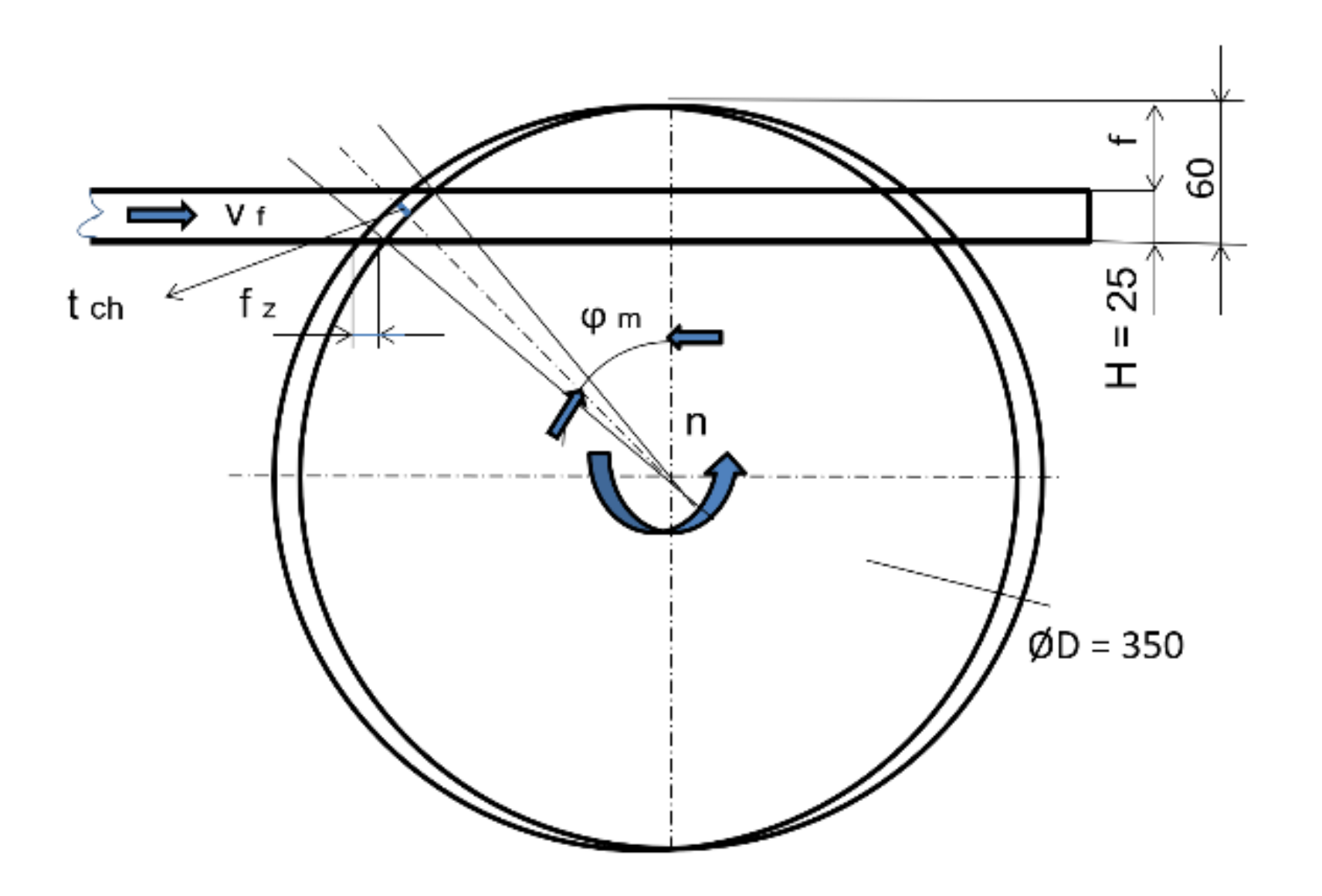
Figure 4.
Effect of the feed speed and the design of the circular saw blades on cutting power.

Figure 5.
Effect of the rotation speed (rpm) and the design of the circular saw blades on the cutting power.
Figure 5.
Effect of the rotation speed (rpm) and the design of the circular saw blades on the cutting power.

Figure 6.
Dependence of the cutting power on the mean chip thickness at all nine cutting conditions.
Figure 6.
Dependence of the cutting power on the mean chip thickness at all nine cutting conditions.

Figure 7.
Dependence of the circular saw blade surface temperature on the feed speed at a shaft speed of 4050 rev/min: (a) CSB1, (b) CSB2, and (c) CSB3.
Figure 7.
Dependence of the circular saw blade surface temperature on the feed speed at a shaft speed of 4050 rev/min: (a) CSB1, (b) CSB2, and (c) CSB3.

Figure 8.
Scheme of a circular saw, including a device for measuring the cutting power and the surface temperature of the circular saw blade.
Figure 8.
Scheme of a circular saw, including a device for measuring the cutting power and the surface temperature of the circular saw blade.

Figure 9.
Experimentally measured values of CSB2 surface temperatures. (Feed speed = 21 m/min, rotation speed = 4100 rev/min).
Figure 9.
Experimentally measured values of CSB2 surface temperatures. (Feed speed = 21 m/min, rotation speed = 4100 rev/min).

Figure 10.
Dependence of the circular saw blade surface temperature on the distance of the sensor from the saw blade axis at a shaft speed of 4100 rev/min: (a) CSB1, (b) CSB2, and (c) CSB3.
Figure 10.
Dependence of the circular saw blade surface temperature on the distance of the sensor from the saw blade axis at a shaft speed of 4100 rev/min: (a) CSB1, (b) CSB2, and (c) CSB3.

Figure 11.
Influence of the average chip thickness on the surface temperature of the saw blade: (a) CSB1, (b) CSB2, and (c) CSB3.
Figure 11.
Influence of the average chip thickness on the surface temperature of the saw blade: (a) CSB1, (b) CSB2, and (c) CSB3.

Table 1.
The basic parameters of the used circular saw blades.
| Parameters | CSB1 | CSB2 | CSB3 |
|---|---|---|---|
| Circular saw blade diameter (mm) | 350 | 350 | 350 |
| Clamping hole diameter (mm) | 30 | 30 | 30 |
| Number of teeth (−) | 36 | 36 | 36 |
| Body thickness (mm) | 2.4 | 2.4 | 2.4 |
| Length of the cutting edge (mm) | 4.0 | 3.8 | 4.0 |
| Tooth height (mm) | 13 | 13 | 13 |
| Tooth geometry | αf = 15° | ||
| βf = 65° | |||
| γf = 10° | |||
Table 2.
Rotational speed, feed speed, and cut height for the nine cutting conditions. Also listed is the corresponding average chip thickness.
Table 2.
Rotational speed, feed speed, and cut height for the nine cutting conditions. Also listed is the corresponding average chip thickness.
| Condition Number | Rotational Speed (rev/min) | Feed Speed (m/min) | Cut Height (m) | Average Chip Thickness (mm) |
|---|---|---|---|---|
| 1 | 4050 | 14 | 0.025 | 0.065 |
| 2 | 4100 | 14 | 0.025 | 0.064 |
| 3 | 4150 | 14 | 0.025 | 0.063 |
| 4 | 4050 | 21 | 0.025 | 0.098 |
| 5 | 4100 | 21 | 0.025 | 0.096 |
| 6 | 4150 | 21 | 0.025 | 0.095 |
| 7 | 4050 | 28 | 0.025 | 0.130 |
| 8 | 4100 | 28 | 0.025 | 0.128 |
| 9 | 4150 | 28 | 0.025 | 0.127 |
Table 3.
Temperature sensor parameters.
| Parameter | Value |
|---|---|
| Power supply | 6...28 Vss |
| Measuring range | −40 ... + 1000 °C (adjustable) |
| Output | 4...20 mA, USB |
| Optika | 30:1 |
| Emissivity | Adjustable via USB and computer |
| Spectral range | 8...14 µm |
| Accuracy | ±1% of value or ± 0.5 °C (whichever is greater) |
| Housing operating temperature | 0... + 70 °C |
| Response time | 240 ms (90%) |
| Dimensions | Ø25 × 106.5 mm |
| Mounting | Thread M20 × 1 |
| Coverage | IP65 |
| Case material | Stainless steel AISI304 |
Table 4.
Analysis of variance showing the influence of the circular saw blade, feed speed, and rotation speed on the cutting power.
Table 4.
Analysis of variance showing the influence of the circular saw blade, feed speed, and rotation speed on the cutting power.
| Parameter | Cutting Power | |
|---|---|---|
| F Value | p Value | |
| Feed speed | 526.24 | 0.000 |
| Rotation speed | 30.57 | 0.000 |
| Circular Saw Blade | 19.44 | 0.000 |
Publisher’s Note: MDPI stays neutral with regard to jurisdictional claims in published maps and institutional affiliations. |
© 2022 by the authors. Licensee MDPI, Basel, Switzerland. This article is an open access article distributed under the terms and conditions of the Creative Commons Attribution (CC BY) license (https://creativecommons.org/licenses/by/4.0/).
Share and Cite
MDPI and ACS Style
Svoreň, J.; Naščák, Ľ.; Barcík, Š.; Koleda, P.; Stehlík, Š. Influence of Circular Saw Blade Design on Reducing Energy Consumption of a Circular Saw in the Cutting Process. Appl. Sci. 2022, 12, 1276. https://doi.org/10.3390/app12031276
AMA Style
Svoreň J, Naščák Ľ, Barcík Š, Koleda P, Stehlík Š. Influence of Circular Saw Blade Design on Reducing Energy Consumption of a Circular Saw in the Cutting Process. Applied Sciences. 2022; 12(3):1276. https://doi.org/10.3390/app12031276
Chicago/Turabian StyleSvoreň, Ján, Ľubomír Naščák, Štefan Barcík, Peter Koleda, and Štefan Stehlík. 2022. "Influence of Circular Saw Blade Design on Reducing Energy Consumption of a Circular Saw in the Cutting Process" Applied Sciences 12, no. 3: 1276. https://doi.org/10.3390/app12031276
Note that from the first issue of 2016, this journal uses article numbers instead of page numbers. See further details here.