Seismic Behavior of Micropiles and Micropiled Structures Used for Increasing Resilience: A Literature Review


Geotechnical Department, Faculty of Hydrotechnics, Technical University of Civil Engineering Bucharest, Bd. Lacul Tei 124, 020396 Bucharest, Romania
*
Author to whom correspondence should be addressed.
Appl. Sci. 2022, 12(5), 2743; https://doi.org/10.3390/app12052743
Submission received: 13 January 2022
/
Revised: 23 February 2022
/
Accepted: 2 March 2022
/
Published: 7 March 2022
(This article belongs to the Special Issue Urban Sustainability and Resilience of the Built Environments)
Abstract
:Featured Application
The paper is useful for those who are interested in the seismic behavior of micropiles and micropiled structures; furthermore, it is presenting the concept of associating micropiles with seismic dampers and the idea of using micropiles to enhance the seismic behavior and resilience of structures (for new structures or to retrofit existing ones).
Abstract
The aim of this paper is to present the relevant information and development available in the scientific literature regarding the seismic behavior of micropiles (MPs) and micropiled structures (MPed). The seismic behavior of MPs is not very well studied, but MPs are used in retrofitting of old buildings and for new resilient buildings, and in terms of seismic behavior they have a high potential. Additionally, their association with seismic dampers for improving the seismic behavior of buildings is not yet fully studied and it represents a major topic of interest for both new structures and historical monuments. After the introductory part, the paper describes all relevant information regarding MPs, as types and technology, seismic behavior, applications for increasing seismic resilience, and experimental and numerical modeling.
1. Introduction
During the 1950s, Dr. Fernando Lizzi developed the so-called “pali radice” or “root piles”, a technical solution consisting of small diameter, vertical or inclined, micropiles (MPs) used to provide additional resistance to the existing foundation or/and soil. Technically speaking, MPs are small diameter piles, typically less than 300 mm, drilled and grouted nondisplacement piles, which are typically reinforced [1]. From the point of view of European execution standards, MPs are neither classified as displacement piles nor as bored piles, and a separate execution standard is provided: EN 14199:2015 [2].
MPs are easy to install in areas with restrictions, such as limited access areas, limitations on vibration, and difficult soil conditions. This is due to the fact the MPs family includes many types and technologies, which give contractors the possibility to develop many “problem-specific solutions”. Figure 1 and Figure 2 present some applications of MPs [3].
The use of MPs increased beyond the initial aimed scope; for example, they can also be used in slope stabilization (Figure 3). The use of MPs in the seismic engineering field was initially limited to retrofitting damaged structures and foundations, but after the 1995 Kobe earthquake in Japan, it was observed that MPs can also be beneficial for the superstructure during the seismic event, and it started to be conceived as a foundation system more than just a repair solution [1].
Many researchers studied the behavior of MPs considering various parameters with similar efforts carried out by several institutions in several countries to develop good understanding of MP behavior. Bruce [3,4] was one of the leading researchers in this field. The series of documents published by FHWA (Federal Highway Administration) in the 1990s and 2000s, ending with the report “FHWA NHI-5-039” [1], represented one of the most comprehensive documents of MPs at that time (even though the focus was not on the seismic behavior of MPs). Several investigations were performed to further study both the general and the seismic behavior of MPs, e.g., refs. [5,6,7]. However, more research and tests need to be performed to expand the knowledge of MPs, considering the rapid development of MP technology.
When describing seismic retrofitting and seismic behavior, seismic dampers cannot be neglected. Seismic dampers are a well-known solution, having the benefit of enhancing the seismic behavior, which in turn leads to a reduction of the total cost, but also having some inconvenience, such as the complexity and the requirements of periodical maintenance, which depend on the seismic dampers type [8].
MPs can provide the same advantage of avoiding damages to the superstructure when being used in retrofitting, plus the relatively simple design and execution, while when considering the ability of enhancing the seismic behavior, seismic dampers are in the lead.
After considering this, a question can arise regarding the possibility of a further study on MPs seismic behavior and their ability to affect the superstructure seismic behavior as well, in such a way that they keep their advantages, and they further enhance the seismic behavior of the superstructure. Additionally, using MPs alongside seismic dampers might provide another possible solution in enhancing the performance of the superstructure, increasing its resilience, while keeping all the advantages discussed previously. To answer this question, research is ongoing for increasing the understanding of the seismic behavior of MPs and MPed structures, the ability to affect and enhance the seismic behavior of the superstructure with using MPs, and by using MPs alongside seismic dampers.
This paper at the beginning presents some very general and synthetic aspects about micropiles in order to set the scene for the further analyses. This paper further refers to the seismic behavior of MPs and MPed, including many actual references found in the literature, along with personal data syntheses and analyses of the results of other authors. No references are made to the static behavior of MPs, which is well known. Additionally, there are some personal contributions provided for using MPs in association with base isolator systems (BIS), which further need studies and research. The association MPs–BIS is briefly approached only from the MPs point of view, the BIS themselves beyond the scope of the paper.
2. General Aspects on Micropiles
Some very synthetic general aspects about micropiles are given hereafter in order to be able to further analyze their behavior depending on how they are designed and executed.
2.1. Classification
Various classification systems are available, among which is the one by FHWA [1]. Table 1 briefly illustrates this classification system.
At European level, EN 14199 differentiates two methods of MPs execution, which can be considered to a certain extent as an additional classification system [2].
According to EN 14199, there are “drilled MPs” with a diameter less than 300 mm, and “displacement MPs” with a diameter less than 150 mm.
2.2. Technology
All stages of MP execution and materials used influence MP behavior; therefore, it is important to present these aspects in a synthetic manner hereafter. The main influence of the technology is on the surrounding soil, which is modified twice, firstly during the drilling process and secondly during grouting. From seismic behavior point of view, it has not been studied explicitly, yet the relationship between the execution technology and the seismic behavior gives no direct relation between a specific technological option and the behavior obtained afterward.
The common drilling techniques for MPs are the overburden drilling techniques (single-tube advancement drive, single-tube advancement external flush, rotary duplex, rotary percussive, hollow stem auger, etc.) or open hole drilling techniques (rotary percussive, solid core continuous flight auger, etc.) [1]. These different techniques can influence the behavior of MPs due to the permanent modifications of the surrounding soil that they cause, e.g., softening the surrounding soil. The fact that type E MPs have a simultaneous grouting and drilling process makes them a good option for reducing the negative effects of drilling [5].
Grouting techniques used for MPs are those noted Table 1 and Figure 4. They can be split into [1]: gravity fill techniques (primary treatment), pressure grouting technique (through the casing), and post-grouting techniques, which has a higher ground-to-ground bond strength and it can be completed in single-step post-grouting such as type C, or in a multistep post-grouting as type D MPs. Grouting materials include sand–cement mortars or neat cement grouts.
The typical reinforcement elements are concrete reinforcing steel bars, continuous-thread steel bars, and continuous-thread hollow-core steel bars.
Depending on the MP type (A, B, C, D, or E), soil type (cohesive/granular), and loading conditions (moderate to high lateral loads usually implies using a drill casing as a permanent resistance element), the drill casing can be temporary or used as a permanent reinforcing element, which can extend to the full or partial length of the MP. Furthermore, an additional smaller diameter pipe is occasionally used with the drill casing (inside the casing) [1,2,10].
Grouting body and drilling casing together form the body of the MP owing to kinematic interaction; they can influence the seismic behavior of MPs and MPed structures. Usually, when studying their seismic behavior, the focus is not on these aspects, but rather on other criteria, which are usually considered when studying seismic behavior of other types of piles, such as length, inclination, pile-to-structure connection, etc. Refs. [3,6,7,11,12,13].
3. Seismic Behavior of Micropiles
3.1. General Aspects about Seismic Behavior of Piles and Micropiles
MPs have a complex behavior that is a function of many factors, starting with the MP itself (e.g., grouting and MP shape), the surrounding soil (e.g., soil dynamic properties and stratigraphy), the superstructure, MP-to-structure connection (e.g., fixity condition), and loading type/intensity [1,3,6,7,10,11,12,13,14].
Thus, it is important to analyze the behavior of MPs based on these factors individually, and then considering the ability of benefiting from each factor. These factors and their influence are presented below.
After analyzing these factors individually, it is important to combine the findings of these analyses to understand the comprehensive behavior of MP and MPed structures; this can be obtained by probabilistic reliability analysis, and then a practical methodology of enhancing the seismic behavior of MPed structures through MPs can be developed.
The mechanism in which the soil, MPs, and the superstructure are interacting together to seismically behave in a certain way is discussed after the factors of influence are presented. How MPs can possibly influence this mechanism is also discussed.
3.2. Factors of Influence
As for other structures, the behavior analysis of MPs should be performed based on the main influential factors. Based on the literature study and making a synthesis of the main findings [1,3,6,7,10,11,12,13,14], the authors’ view on the main factors influencing MP behavior is presented in Table 2, grouped into four main categories: factors related to micropile itself, soil-related factors, connection with the structure, and loading-related factors. These factors are detailed and further analyzed.
3.2.1. MP-Related Factors
Noted that it can be misleading, to a certain degree, to manage MPs as one type of pile that exhibits different behavior in function of some factors, and it may be more appropriate to manage MPs as a family of piles. For example, when studying the seismic behavior of type-A MPs (grouting under gravitational head) and comparing it with the seismic behavior of type-D MPs (multiple-steps post-grouting), one should expect that the behavior of the whole system will be different, starting from the MP itself, to the soil, and the superstructure. Hence, special attention should be given when interpolating MP studies/tests results as they may not be appropriate for a global consideration on all MPs [6,14]. As well, as stated before, the technology highly influences the behavior; presented below are some examples of technological influence on the behavior of MPs.
As for example, Capatti et al. [6] performed a field test on two MPs with two different grouting methods (gravitational and pressurized) to study their dynamic response. The test was performed in an alluvial silty deposit, with two MPs 8 m long for each. As stated above, one was grouted under gravity head only and a hollow-core steel bar was installed, while the second was initially installed in the same way but had an additional grouting step. MPs were instrumented for monitoring with sensors, and the tests performed were ambient vibration tests and impact load tests. Not only was the response different between these two MPs, but there were also differences on the level of the pressurized MP itself, as the behavior was different in the two orthogonal horizontal directions. According to [6], the pressurized grouting modified the surrounding soil, which led to a modification in the soil stiffness and resulted in the response differences between these two MPs. Additionally, since the direction of the pressurizing process was different (one direction was pressurized directly), it led to another difference in the stiffness level of the soil and the dynamic response as function of the pressurizing direction [6,14].
In a similar manner, Mashhoud et al. [7] performed a shaking table test to study the dynamic behavior of MPs in loose sand; the outcome of the test can be beneficial in terms of kinematic interaction. A densification phenomenon of the surrounding soil around the MPs took place according to the author; this densification can be due to the excitation source and/or influence of the MPs. From the point of view of enhancing the seismic behavior of the superstructure, MPs provide wide possibilities for modifying the soil, in small or relatively large ranges, as also noted by other authors [14]. The pile cap itself or the MPs were out of phase with the base shaking; theoretically, this results from the stiffness and damping differences between the soil and the MPs/MPs cap.
Heo et al. [15] confirmed this phenomenon through a comparative study on three MPs: one was also a gravitational MP, while the other two were pressurized. The difference among them is the type of packer used during the grouting process; furthermore, the differences in the measured “resulting” stiffness after MP installation were extremely high between the three cases. The predicted (based on the cross-section properties, same for all three cases) and measured elastic modulus of the first MP (gravitational MP) were very close to each other, as the measured stiffness had a value almost 10% higher than the predicted one, while the first pressurized MP with a geotextile packer (the common practice) had a measured stiffness value of almost 40% higher than the predicted one. Interestingly, the second measured MP that used a rubber packer reached a value almost 120% higher than the predicted one, similar to using a rebar element of 147.6 mm diameter instead of 81.3 mm, which was the one used in the test. The reason for that, according to the paper’s author [15], is the use of the rubber packer that has a nozzle that drains the slime inside the borehole, which usually develops when using geotextile packers; draining the slim results in a better grouting and thus better performance [15].
Ghorbani et al. [11] performed a comprehensive analysis of seismic performance of a soil–micropile–superstructure system in interaction, starting with a parametric analysis to measure the influence of selected parameters, and then followed by sensitivity analysis to determine the most influential parameters on the performance. The analyzed parameters were inclination angle, MP spacing ratio, MP diameter, etc. Authors concluded that in terms of maximum shear and bending stresses in the MPs studied, the number of MPs used and the slenderness ratio (L/d = 20–60, where L is the length and d the diameter) are among the most influential parameters (the difference in the values of the shear and bending stresses is more than 35% between the cases studied), while MP diameter (d = 0.25–0.45 m) was not so important, which is similar to the behavior of other types of piles [11].
Based on these literature results, it can be affirmed that the behavior of MPs is a combination between the behavior of a “normal” pile (more precisely a bored pile), but modified primarily due to the technological differences of the MP installation process, and for this, when a gap in the literature exists regarding a certain aspect of MP behavior, it is common to rely on other sources of literature. This is reflected in the design and analysis process, as many practices are adopted from the ones used with other types of piles. However, occasionally this is done without real or sufficient calibrated data. This practice was accepted in the past in some cases when a sufficient experience existed and MPs were not used to carry an important structure, but at present, it can no longer be accepted, as MPs are involved increasingly more in very complex and important projects. Furthermore, considering the advancement in MP technology, experience alone may no longer be sufficient [1,2,3,10].
Shahrour et al. [13] studied the effect of MP inclination on the structure dynamic amplification factor, and again a strong relation was found between MP angle of inclination and the amplification factor, which might be due to the stiffness differences between vertical and inclined MPs or to the kinematic interaction. Inclination effects can also be found in [16], which considers the load sharing between the MPs and MPR (micropiled raft). When the inclination angle increases, the part of the load carried by the MPs from the total load imposed on the MPR also increases [13,16]. In the following figures, some results are presented for comparison. Figure 5 (modified after [13]) shows how the response (the acceleration in this case) is influenced by the MP’s inclination angle, once for the pile cap (Cap) and then for the attached mass (Mass) for two excitation types: harmonic and time history record (called “seismic” on the graph in Figure 5). Figure 6 (modified after [12]) shows how the dynamic amplification factor is influenced by both the fixity condition (fixed or pinned) and the MP’s inclination angle (0°, 20°) for two values of the frequency, both for the pile cap (Cap) and for the attached superstructure (structure).
It can be seen from the first chart (Figure 5) that increasing the MP’s inclination led to increments in the acceleration of both the cap and the attached mass (dynamic amplification factor increases) in the case of the harmonic excitation. While in the case of time history records, this increment occurred slightly in the case of the attached mass until an angle of inclination of 10°, then it declined, while for the cap it was a slight declination from 0° to 30°. In the second graph (Figure 6), it can be seen that in all cases the amplification factor decreased with the inclination angle increasing, with the exception of Cap/Pinned with f = 0.5 f1.
For the kinematic interaction of MPs when studied in terms of the MP’s inclination angle, it can be concluded from these two studies that the same trend of results cannot be obtained for different excitation sources. This can be important for research when searching for the benefits from MPs in enhancing seismic behavior; any study needs to include several excitation sources of different nature.
3.2.2. Soil-Related Factors
Soils can influence the seismic behavior based on the way that they are interacting with MPs or in the way they are influencing the propagation of the seismic waves [17]. This interaction can affect the seismic input motion, as further described below.
For example, Kaynia et al. [18] studied the influence of soil homogeneity on the seismic behavior; the results showed a strong deviation between the two studied cases (homogeneous and heterogeneous soil) in terms of damping value and consequently the seismic response; it was observed by the authors that the two types of soil differ considerably in terms of horizontal response and damping value. This concept was referred to by the authors as “filtration” of the high frequency component of the ground motion. Taking into consideration the drilling and grouting process of MPs, a certain level of heterogeneity can result, which can further influence the seismic behavior through an “artificial filtration” or, more precisely, a “damping out the high frequency components” of the seismic ground motion.
The soil mass, which is modified owing to the existence of MPs, forms a composite MPs–soil block that amplifies the seismic waves [19]; by analyzing the wave propagation in the modified soil due to the existence of MPs, it is possible to use these MPs as a factor of enhancing the seismic behavior by affecting the wave propagation in the soil. This topic is not precisely studied, but some indirect conclusions can be extracted from the existing literature, such as those that have been discussed previously [6,11,12,13,14], and it is aimed to be further investigated in the future by the author.
3.2.3. Factors Related to the MP-to-Structure Connection
The usual approach when problems involving MPs are analyzed through numerical methods is to model the connection between the MP top and the pile cap as perfectly fixed or pinned; this approach is the same followed with other type of piles, such as bored piles (type-A MPs is the closest type of MPs family to bored piles). However, MP connection-to-structure is more complex due to the installation process and MP structural components. Neglecting this complexity can be beneficial in terms of seismic behavior, since it undergoes high potential of plasticization and nonlinearity during seismic events, which in turn can be a source for increasing the damping value.
As an example, the influence of MP-to-structure connection was studied numerically by Sadek et al. [12], more precisely the influence of fixity condition: fully fixed or fully pinned. The authors concluded that the dynamic amplification factors for both the pile-cap and the superstructure are strongly dependent on these fixity conditions. Again, in real practice, MP-to-structure connection is neither fully fixed nor fully pinned, but commonly assumed to simplify both the design and analysis [12].
More advanced numerical and analytical methods might be necessary in estimating the stiffness of the connection to give a precise estimation in the numerical model and to account the nonlinearity of the behavior, which is a topic that has not been thoroughly approached for MPs. This zone (superstructure base until the first few meters of the MP) is extremely critical for the overall behavior (MPs, soil, superstructure) due to the complexity of the interaction between the components, which influences wave propagation. Additionally, influential phenomena on the inertial interaction, such as grouting/soil debonding, cracking, and plasticization of the structural elements, are more likely to occur in this zone due to the concentration of internal forces. The sensitivity of the seismic behavior to the upper soil profile was also observed by Kaynia et al. [18], but the authors related their observations to the soil heterogeneity, which causes what they called “filtration”. When considering more accurately the effects of all components in this zone, e.g., gap formation phenomenon in the soil–MP interface, together with the concept of filtration discussed above, the influence on the inertial interaction can be understood more precisely and deeper results can be concluded [13,14].
3.2.4. MP Seismic Interaction Factors
To further expand the discussion regarding MP role in the seismic behavior, it is important to demonstrate the mechanism through which soil–foundation–superstructure are all interacting together when excited by a seismic motion; this mechanism is influenced by all the factors and subfactors previously mentioned.
The free-field motion applied to a building and its foundation are transferred into a foundation-input motion due to the kinematic interaction. This latest is the one that determines the excitation in the structure [17,19]. Furthermore, the structure, its foundation, and the surrounding soil all interact due to this foundation-input motion; this type of interaction is called inertial interaction [17,19].
The kinematic interaction is the product of wave incoherence, which can be due to the foundation shape (footprint) and embedment depth, as the medium in which the waves are transferred through starts to differ when arriving to the foundation. Usually this causes a decrement of the foundation input motion, while the inertial interaction is due to the flexibility of the system and damping (both hysteretic and radiation damping) [19].
MPs have an important influence on the kinematic interaction, as the embedment depth is relatively high, it can cause incoherence in the seismic waves, also due to the footprint area, the angle of inclination, and the installation method (technological effect). This influence is generally assumed to be positive, but also minor or even negative influence can be potentially obtained, as the outcome of the interaction is not only a function of the soil and MPs, but also depends on the seismic wave progression and diffraction. Furthermore, MPs can also affect the inertial interaction through both stiffness and damping. This is expected (pile effect due to the embedment depth) as it was noted with other type of piles, but this is a sensitive topic; for example, increasing the stiffness of the soil leads to an increase in the stiffness of the system (soil–MPs–structure), and depending on the excitation source, this can move the seismic response away or closer to resonance [6,17,20] (Figure 7).
Complex SSI (soil–structure interaction) analysis might be a good option to manage seismic wave propagation issues, similar, for example, to the recent work of Conțiu et al. [21], which compared the structural response of a bridge pier using analyses with different levels of SSI complexity. The authors also compared the deterministic approach and simple design methods with a probabilistic approach. The latter allows for more accuracy in modeling the soil dynamic properties, which can also be very helpful in studying the seismic behavior of MP and MPed structures, as a probabilistic approach can capture more accurately and in detail the local behavior of the soil that is influencing wave propagation.
Referring to seismic waves, they are divided into two types, body and surface waves; in many cases the focus is on body waves, as in most of the discussed papers. Even so, the foundation is excited by both types and not considering these two types of seismic waves in the studies may limit the ability of reaching rigorous conclusions. Two possibilities exist: body waves arrive before surface waves or intersecting of body and surface waves. From the point of view of the authors, the role of MPs can be useful in decreasing the potential hazard of the “softening” phenomenon, which is related to the difference in the arrival of the seismic waves; this can be potentially achieved again by influencing the damping and stiffness value (inertial interaction) or by considering that the surface waves are also subjected to the kinematic interaction as well as for the body waves [17,19].
Additionally, by returning to the influence of MPs on the dynamic response of the structures, discussed previously, this influence was generally detected as a function of the displacement response, modification of the natural period, or the inertial forces of these structures. Unfortunately, the frequency band was not clear in all of the papers reviewed, but it is globally assumed that the measurement was performed for both broad-band and narrow-band, as some papers performed a dynamic pile load test, while others performed numerical analysis to study the behavior of MPs excited by either a harmonic motion or by actual earthquake records [6,7,11,12,13,14].
Based on the knowledge of the authors, there are no explicit studies that consider all these effects of the parameters, but there are studies of the seismic behavior of MPs and MPed structures, as discussed before, and these parameters are already included indirectly. Therefore, to develop good understanding of the effects of MPs on kinematic and inertial interactions, at least the following must be demonstrated:
- Effects of the MP embedment length on the foundation-input motion;
- Effects of MP inclination on the foundation-input motion;
- Effects of the MP installation method on foundation-input motion;
- Damping ratio considering MPs;
- Modification in the natural frequencies as a function of existing MPs.
3.3. Behavior of MPs in Association with Seismic Dampers
As MPs are commonly used for retrofitting existing buildings, an enhancement of the seismic resilience can be obtained by associating MPs with seismic dampers. In this paragraph we are not treating the seismic damper aspects but the association MPs–seismic dampers, which is a quite new subject not fully treated in the literature.
We further expand the discussion into the field of damping and seismic dampers, as damping in any structure is a combination of intrinsic, aerodynamic, hysteretic, and supplementary damping. Supplementary damping can be obtained by adding damping devices; these devices can help enhance the seismic response by increasing the damping value, decoupling the superstructure from the seismic motion, or combination of both ways [8,22,23,24].
Related to this and returning to the introduction, two questions can arise. The first question is the ability of MPs to behave in a way that enhances the seismic behavior similar with the seismic dampers, meaning increasing the damping value (inertial interaction) and the effect on the kinematic interaction. It is expected that when using MPs, the stiffness of the system increases [6], but also the incoherence, as MP technology induce modifications to the surrounding soil, firstly during the drilling process, which is a symmetrical modification, and secondly due to the grouting process, which can be a simple (under gravity) or complicated process with asymmetrical modifications (in the two horizontal directions) and in terms of the vertical grouting profile. Thus, it is very interesting to study wave transformation and the coupling/decoupling of the applied forces with the system due to MPs. This can be done with the same procedure as for other types of piles, as in the work of Xie et al. [25], who performed numerical analysis validated by shaking table tests; or analytically, as the in the work of Medina et al. [26] who used an analytical solution to calculate the response of a structure (Q) as a function of several parameters, e.g., kinematic interaction factors and impedance functions. The same concept can be used for MPs, after investigating how these parameters can be suitable for each type of MP; for example, the impedance function that allows for soil stiffness and damping coefficient can be expanded to be “unaffected” by soil stiffness and damping coefficient, which are added to the “affected” by soil stiffness and damping coefficient due to MPs, and eventually the final matrix can be formed.
Equation (1) is the impedance function as presented in [26], with the soil stiffness and the soil damping coefficient. In Equation (2), and are the unaffected and affected soil stiffness values, respectively, while and are the unaffected and affected soil damping coefficients, respectively, as proposed; these values can be obtained from numerical models or by analytical equations.
The second question is whether it is beneficial to combine seismic dampers with MPs; this combination might help in increasing the damping value, as not all damping devices increase the damping value sufficiently, as many of them mainly decouple the superstructure from the input motion [27]. Thus, adding MPs might combine these two enhancements in the behavior. Development and research on base isolator technologies to increase the damping value is an ongoing process and a subject of a great interest, with numerical studies being developed, for example, as for LRB (lead rubber bearing) and RRB (rubber bearing with steel rings) [28]. There are many other innovations for enhancing the performance of base isolators. Diyar et al. [29] studied the effect of increasing the number of the lead cores, and the effect of changing the shape of the base isolators; instead of circular, rectangular shapes were studied numerically. The results showed that the differences between the two directions (length vs. width of the isolator) were not that important; however, the number of lead cores played a significant role in increasing damping value [29]. Thus, increasing the damping value by using a method different than interfering to the base isolator structure, as using MPs, might be an interesting idea.
MPs can also provide a stiff base, which is usually recommended for base isolators [8]; also, such a combined solution can be very useful for retrofitting existing structures and especially historical ones; as modifying the superstructure is not allowed in such cases (historical structures) or it can be difficult; a combination of MPs and base isolators can provide the solution, as MPs help in increasing the foundation capacity, soil stabilization, and potential benefit in both kinematic and inertial interactions, while base isolators decouple the superstructure. Finally, the structure is retrofitted from geotechnical and seismic points of view, also by using MPs with the base isolators, the necessity of using large diameter base isolators might be reduced, depending on the way that MPs can help the base isolators. One example of seismic retrofitting with base isolators is St. Nicolae Aroneanu church in Romania, where base isolators were installed under an historical masonry church [30]. Additionally, this was suggested and studied numerically by Usta [31], who confirmed the suitability of base isolators in such cases, without intervention to the structural system
To summarize, combining MPs with seismic dampers may positively influence the double enhancement of seismic dampers; these enhancements provide decoupling and increase damping value. Seismic dampers can do both, or mainly decoupling (for base isolators); here, MPs can either help in increasing damping value, which develops these basic base isolators from only a decoupling solution into a decoupling + increasing damping value solution. This also means that they can be used to optimize the base isolators, after taking into consideration the increase in damping value that they potentially provide. Alternatively, they can influence the decoupling phenomenon itself, indirectly by influencing the input motion, which may also lead to an optimization in the base isolator size [8,22,27]. This need to be further studied in detail to understand the influence of MPs on these two aspects.
To better illustrate the idea of combining MPs with seismic dampers, the following figures are presented, starting with Figure 8, Figure 9 and Figure 10, which present some typical details for base isolator attachment [20,32,33], and then Figure 11, Figure 12 and Figure 13, which also present some typical details for MP connections to a structure (new or existing) [1]; and finally, Figure 14, Figure 15 and Figure 16, which present new proposed details for combining MPs with seismic dampers; these three proposed details can be used for new structures as well as for existing structures. These are details proposed by the authors and they need extensive research in order to know their behavior and whether it is actually beneficial or efficient for seismic resilience applications. For achieving this, the authors start with the validation of the proposed connection from a structural point of view, completion of the understanding of the seismic behavior of MPs and MPed structures with the notes drawn by this paper, and continue with experimental tests and suitable numerical tests for these models.
In Table 3, a comparison between the three new proposed details is presented.
4. MP Modeling by Experimental and Numerical Methods
Numerical modeling allows the analysis of a certain subject with many parameters in a relatively short time; additionally, besides the time that it can save to reach some results, it saves many resources. However, any numerical model needs to be calibrated so the results can be trusted, and this can be done by experimental modeling. Additionally, experimental modeling can obtain the desired results directly without approaching any numerical modeling, and with a higher level of accuracy [17].
Unfortunately, for a comprehensive experimental study where there are many variants to be considered, the cost and time consumption is extremely high in order to study all the possible situations, and this is why numerical modeling is usually the selected method but associated with a calibration based on experimental tests; one of the widely used experimental methods in geotechnical engineering (for piled structures) is the shaking table and centrifuge testing [17,34].
Considering the fact that these two methods usually cannot fully simulate the technological aspects of different MP installation methods (as the test is scaled and considering these aspects is difficult), and they use different materials than the actual ones that MPs are using, experimental modeling may not be an exact simulation of MPs. Moreover, an available performed test does not always exist, as MPs are in continuing development. Load tests of actual MPs can give sufficient data in this case; the data from these load tests are usually the core in calibrating the numerical models of MPs and developing any design procedure [1,10,17], but for research they are not offering the possibility to test every relevant situation. Mohr–Coulomb (MC) is the most widely used failure criterion in geotechnical engineering problems, which also applied to piled structures. Associated and non-associated flow rules are also used, with classical (elastic perfectly plastic) and modified (strain hardening/softening) criteria. Considering MC in the analysis offers the benefit of reducing the necessity of performing in situ tests for calibration and validation where such tests had already been conducted and, also, the number of parameters is reduced (five parameters) and easy to obtain, as they do not require special tests. Additionally, it presents an added advantage in the case that new tests are required [34]. Other failure criteria have also been reported in the literature, such as modified Cam–Clay (MCC), but most are not calibrated/validated sufficiently based on tests, therefore we did not include them in extenso in the present review.
If the requested data of MPs behavior are not available and time-consuming performing tests are not possible, works performed on other types of piles can be considered, especially those with a high length/diameter ratio (for MPs can be as high as 50–100) [1,10,12].
In Table 4, a summary of selected papers related to the seismic behavior of MPs and other interesting aspects is presented, proving for each one the general scope and the analysis method, followed by some remarks. This table needs to be read in conjunction with Table 2 and Table 5. Some of these papers were discussed previously, and some are discussed further. The authors consider that the synthesis provided in Table 4 can be very useful for readers interested in one or the other aspects already treated in the cited literature.
Some of the aspects reflected in the analyzed papers concerning the behavior of MPs are presented below, in which MC criterion was used for the numerical models, some being validated and calibrated (both numerical and experimental tests had been performed). The main goal of the present review on this topic is not necessarily the conclusions of these papers, but the ability of the numerical modeling through the selected constitutive model (CM) to reproduce the behavior resulted from the experimental tests, whether it was MPs only or a complex system with MPs, soil, and superstructure, but to also give the reader an idea of the factors (Table 2) that have already been investigated and calibrated with the most used MC criterion.
Shahrour et al. [13] performed a 3D analysis to study the seismic performance of inclined MPs by using a non-associated MC criterion; the study was not explicitly calibrated, but it showed an agreement with the normal expected behavior when using inclined piles. Further, it showed the importance of accounting for soil plasticity in the analysis, as the response between elastic vs. elastic–plastic analysis showed high differences. According to the authors, this is due to the allowance of energy dissipation by plastic deformation. In fact, considering plasticity in the analysis can reduce the resulting response in many cases, which is also an expected behavior. Neither the soil property nor the interface elements are clear in the study [13].
Alsaleh et al. [35] also performed a numerical study to show the effect of considering soil plasticity in the analysis, which can influence the seismic soil–MP–structure interaction, but again no explicit validations/calibrations were presented. The failure criterion used was non-associated MC; the analysis was performed on both harmonic and actual earthquake records and the results showed again that the behavior is strongly influenced by soil plasticity. MPs were modeled as a three-dimensional elastic beam element, damping was considered with Rayleigh method, and a viscous dashpot was used to couple the main grid to the free-field grid. This is a common practice in numerical modeling of piles and it was used here with MPs [35]. With harmonic excitation it was found that the elastic response is 100% higher than the elastic–plastic one. The authors of the paper argued that this is due to the dissipation of energy by plastic deformation and the effect on the stiffness (plasticity leads to stiffness reduction). Additionally, the inertial forces in MPs, when considering elastic–plastic behavior, showed a reduction in their values in comparison to the elastic one, which is due, according to the authors, to the energy transmission reduction related to the plasticity. With seismic excitation, the dynamic amplification factor was reduced when considering elastic–plastic analysis; furthermore, the dominant frequency was modified. These phenomena are similar to those found when studying other types of piles and show the importance of plasticity in the analysis [35].
Gobrani et al. [11] performed a parametric study and a sensitivity analysis on the seismic performance of soil–MPs–superstructure. The authors considered in the study a nonassociated MC criterion and it was validated by a single-degree of freedom shaking table test. The soil considered in the study was sandy with zero cohesion. They used a contact element to model the interface between MPs and soil. The importance of this study is that as many parameters were considered in the numerical analysis, parameters which directly concern the soil and affect CM inputs. Soil nonlinearity, plasticity, and soil internal friction angle were all considered. The behavior that was found is in accordance with what was discussed before and the usual behavior of other types of piles [11].
Alnuaim et al. [36,37] performed a numerical study on the performance of MPed rafts in sand and clay; the study was calibrated with a centrifuge test. The CM used in the analysis was MC, linear elastic perfectly plastic, with interface elements to model the interaction between MPs and the soil; the interface elements also adopted MC criterion, and according to paper’s authors, the results of the numerical analysis showed good agreement when they had been calibrated with the centrifuge test results [36,37].
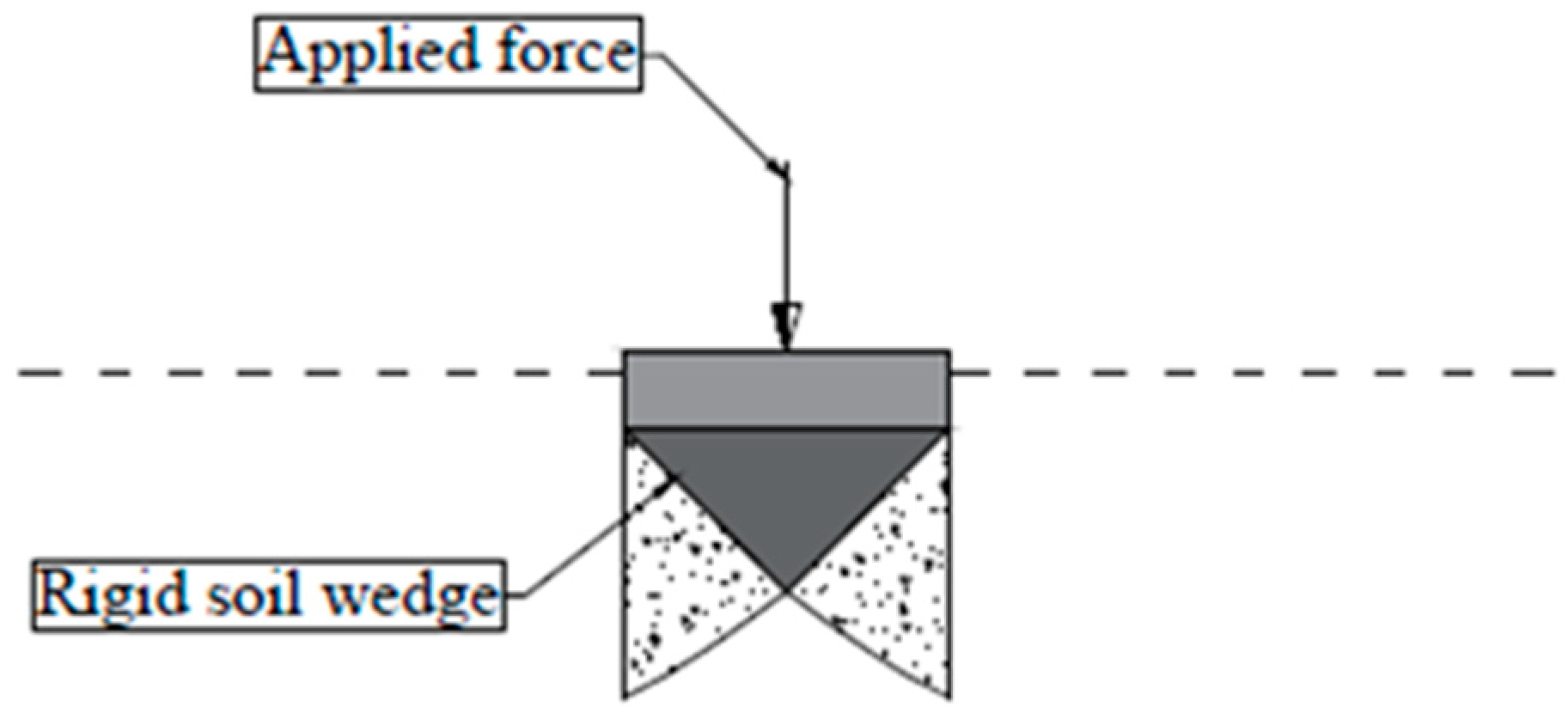
Hwang et al. [38] performed a numerical study validated and calibrated with a model test device. The aim of the study was to investigate the effectiveness of several installation methods of MPs that can affect the bearing capacity by modifying the failure mechanism. Several installation methods were tested, inclination angles or lengths of MPs, and the failure mechanism was monitored for each case, both in the numerical study and for the model test device [38]. The numerical analysis was able to replicate the failure mechanism and the changes occurred when modifying the installation method. The soils used in the study were medium dense sand and clayey silt, for which the MC failure criterion was used. According to the authors, the results showed agreement with classical soil mechanics, as general shear failure occurred in the sandy soil (Figure 17), while punching shear occurred in the clayey silt (Figure 18) and the modifications in the failure mechanism were based on these two concepts. Not only the ability of the numerical model to accurately simulate the failure mechanism is interesting, but also the ability to model the confinement effect, which has a large influence on the seismic performance of MPs and the superstructure, since the size, depth, and location of soil which is contributing to the failure mechanism can affect the soil stiffness, which in turn can affect the seismic performance [38].
More examples of experimental methods can be found in the works of Elaziz et al. [39], Wang et al. [40], and Abbas et al. [41]. Elaziz et al. [39] performed field tests on full scale MPs of type E (self-drilling); the aim of the study was to evaluate the bond strength of grouting/ground; the outcome of the study showed that the value usually taken from FHWA [1] is less than the actual value of the bond strength that can be developed. From the numerical analysis point of view, the test results showed the importance of performing a nonlinear analysis when analyzing MPs that are excited by cyclic loads, as head movement can accumulate, and the existing possibility of a gap creation between the MP and the surrounding soil. These are well-known phenomena with other types of piles, but there is no coherent study as in the case of other types of piles. The outcome of such a study can be important for the inertial interaction.
Wang et al. [40] studied the load sharing between the existing piles and newly installed MPs through a model test; two types of MPs were studied, a waveform MP (WF), which is a new type of MP, and a conventional MP (type A). The outcome showed that the waveform MPs are always contributing more to the load sharing as a percentage vs. the conventional MPs used in the experiment; according to the authors this is due to the fact that the waveform MPs have a higher stiffness than the conventional MPs used. This is true for the MPs used in this particular test, but other type of MPs can potentially have a higher stiffness due to the grouting technology.
Abbas et al. [41] performed a model test and a numerical study on the load capacity of MPs embedded in rocks. MC criterion was used in the numerical analysis, which showed good agreement with the results from the model test. The importance of this study is the sequence of installation of the MP models during the model test, as borehole drilling was simulated somehow, but grouting was performed in a similar manner that for type-A MPs (from an influence point of view), as it took a place before inserting the MP into the soil deposit, which means that theoretically there was no important modification of the soil.
As stated previously, MC is not the only CM used for MP or MPed structure analysis, but it is the one most used with sufficient calibration and validation. Other examples of MPs numerically modeled with different CM can be found; for example, El Kamash et al. [42] studied the efficiency of underpinning of existing footings with MPs in order to decrease the long-term consolidation. In this case, the CM used was MCC and it showed good agreement with the results of the field test. This is one of the very rare papers dealing with MPs numerically with a CM different than MC, and it will be interesting to conduct more research with such an advanced CM in order to study the seismic behavior of MPs.
Another example of numerical modeling calibrated by experimental modeling can be found in the work of Talpoș et al. [44,45], which examined rigid inclusions having some similarities with MPs. The numerical model showed good agreement with the shaking table test performed and, according to the authors, it was able to simulate the dynamic behavior sufficiently. The results indicated a relation between the soil’s elastic modulus, its Poisson ratio, the rigid inclusion elastic modulus, and the distance between inclusions with the natural frequency, which further proved the ability of numerical modeling to simulate many aspects of the dynamic behavior of MPs or elements similar to MPs.
To draw final conclusions of what was presented previously, Table 5 contains the elements in Table 2 that are considered important for the seismic behavior of MPs, with some comments regarding what has been achieved thus far in the research field and what needs to be investigated in future studies. This can be helpful for researchers who are aiming to perform comprehensive studies on the seismic behavior of MPs, or to study the possibilities of benefiting from MPs in seismic resilience applications.
5. Discussion
Discussions were previously presented (Section 2, Section 3 and Section 4) for each aspect that was considered. What follows is a synthesis of the aspects discussed.
MPs have complex behavior that is a function of many factors: type of grouting, MP shape, surrounding soil (in this case mainly soil dynamic properties and stratigraphy), superstructure, MP-to-structure connection, loading, among others. In Section 3.2, a synthesis of these factors of influence is presented, as the authors’ point of view and each one is discussed in detail.
As far as the MP-related factors are concerned, the studies found in the literature and the authors’ analyses showed that the execution technology highly influences the seismic behavior of MPs, especially the grouting method, owing to the modifications that are produced in the surrounding soil, including densification and stiffness increasing, depending on the technology and also some execution details (type of packer, for example). Even if some studies can be found in the literature on these execution aspects, for instance, there is no clear relationship between a certain method and a specific behavior. The geometrical features of MPs, such as the inclination, length, diameter, or spacing, also influence the seismic behavior, being found that the most important are the slenderness (L/d) and the spacing (number). Additionally, the inclination was found to strongly influence the amplification factor, owing to stiffness modification between vertical and inclined MPs, but also the load repartition between MPs and the raft. The modifications that the inclination is leading in terms of dynamic amplification occurs both at the level of MP cap and attached mass, with some differences found when different excitations are applied (harmonic or actual seismic event) and for various types of connection between the MPs and raft.
The factors related to the surrounding soil that interacts with MPs are, of course, also important, as the soil influences the propagation of the seismic wave. Therefore, this interaction can affect the seismic input motion; the homogeneity, stiffness, or constitutive model of the soil influence the behavior. It was found that the damping values and the seismic response in general are affected by the heterogeneity of the soil, and a concept of “filtration” of the high frequency component of the ground motion was proposed by certain authors. Taking into consideration the drilling and grouting process of MPs, a certain level of heterogeneity can result, which can further influence the seismic behavior through an “artificial filtration” or, more precisely, a “damping out the high frequency components” of the seismic ground motion. Additionally, the modified soil mass around MPs, forming a sort of MPs–soil block, was found to amplify the seismic waves. Therefore, a conclusion can be drawn, that it is possible to use these MPs as a factor of enhancing the seismic behavior by affecting the wave propagation in the soil. This is one of the aspects not yet studied, but some indirect conclusions could be extracted from the data presented in Section 3.2. These aspects are aimed to be further investigated in the future by the authors of the present paper.
MPs are expected to affect the seismic behavior by influencing the mechanism of interaction within the soil–micropile–superstructure system owing to the excitation of seismic waves; this can be enacted by affecting the kinematic and/or inertial interactions. MPs have an important influence on the kinematic interaction, as the embedment depth is relatively high and can cause incoherence in the seismic waves. MPs can also affect the inertial interaction through both stiffness and damping, as was also noted for piles. However, increasing the stiffness of the soil leads to an increase in the stiffness of the system (soil–MPs–structure), and depending on the excitation source, this can move the seismic response away or closer to resonance, as shown in Figure 7.
The most relevant papers and results are presented in Section 3, together with some personal views, remarks, and analyses of the authors. Based on our knowledge, there are no explicit studies that consider all the effects of these parameters. Therefore, our conclusion is that, in order to have a comprehensive understanding of MPs effects on the kinematic and inertial interactions, it is necessary to study this in detail, which will be done in the future. Topics such as MP embedment depth, MP footprint, MP damping, MP technology, and stiffness of the composite MPs and soil, are aimed to be studied to enable measurement of their influence on the interactions. By developing a measuring tool of this influence, a further study to determine the possibility to perform some modifications in the MP layout (embedment depth, inclination, technology, etc.) to modify the behavior in a positive manner can be approached. Some of these points have already been studied indirectly, but there is no comprehensive study that can be developed to a practical solution. More work on the seismic behavior of MPs and MPed is needed (in particular, experimental tests), especially with MPs with advanced grouting technologies.
The association of MPs with seismic dampers can also lead to positive results. In the case where MPs are associated with base isolators, as discussed before, MPs might lead to an optimization in the seismic damper size; this can be a result of MPs damping (inertial interaction) or by decreasing the foundation input motion that the base isolators are aimed to decouple the superstructure from (influence of kinematic interaction). Additionally, a combined solution of MPs and base isolators might stand as one of the optimum solutions to be used in retrofitting, especially for historical buildings; the combined solution will increase the foundation capacity together with enhancing the seismic behavior and resilience with minimum disturbance to the appearance of the superstructure. In order to achieve this, it is important to study the behavior after combining MPs with base isolators and to understand this behavior in detail; this will be examined in the future and based on (but not limited to) the previous proposed details (PD.1–PD.3 in Table 3).
In Section 4, the experimental and numerical modeling of MPs are presented, showing the relevant results found in the literature concerning the influence of the factors discussed previously. A synthesis and compilation of the results has been proposed in Table 5 showing the main findings and relevant aspects. It was demonstrated that experiments are available in the scientific literature on some cases that do not completely cover all types of MPs or all situations, but these offer useful data that can be further used for calibrating and validating numerical models. These latest can offer a wide range of possibilities for studying seismic behavior of MPs and MPeds. Some important aspects are presented Section 4, especially regarding the constitutive model, showing that most of the results have been obtained and validated using the Mohr–Coulomb model; very few papers present other constitutive models or provide validation through testing. Most of the aspects discussed in this chapter are related to soil and its modeling, given the focus of the paper on geotechnical aspects.
6. Conclusions
The paper provides a comprehensive literature review on the seismic behavior of micropiles (MPs) and micropiled structures (MPed), which are not yet completely studied.
MPs are used often in the retrofitting of old buildings and for new seismic-resilient buildings, and have high potential for such applications. Additionally, their association with seismic dampers for improving the seismic behavior of buildings is an interesting topic for both new structures and historical monuments. This paper introduces this association.
General aspects as MPs classification or technology are presented in order to have a general picture and to establish common terminology. The seismic behavior of MPs and MPed was presented in detail, showing the main findings in the specialty literature. Association of MPs with seismic dampers is also addressed along with the results of experimental and numerical modeling using MC–CM.
It is shown that in terms of the existing data in the literature, MP and MPed structures still lack sufficient data on their seismic behavior, and more research efforts to further investigate the behavior are necessary. The mechanism by which MPs can influence the seismic behavior is discussed in detail, and it is shown how MP installation can influence it. This needs to be studied more in detail in the future to demonstrate the exact influence of MPs on the kinematic and inertial interactions and the ability of benefiting from this. A practical solution to use MPs in engineering practice of seismic resilience applications can be developed with analytical tools, after performing sufficient studies and testing.
Several details are newly proposed that can achieve the association of MPs with base isolators, the possible benefits of such an association are mentioned in the paper, but this also needs to be studied later in detail.
The availability of calibrated data concerning MPs with MC–CM is discussed and it is shown that the MC failure criterion is commonly accepted to represent the soil by many researchers, although there are available some attempts to use other more advanced constitutive models, but without experimental validation or calibration.
MC–CM is preferable for use in numerical modeling, as it needs a small number of parameters (five). Furthermore, since it is the most used and calibrated CM with MPs, the MC–CM stands as the most effective CM that can be used in a comprehensive study.
Nevertheless, to make a comprehensive study of MPs by numerical modeling, calibration in many cases is required, so that results can be trusted.
Author Contributions
Conceptualization, M.A.A.; methodology, M.A.A. and L.B.; validation, L.B.; resources, M.A.A.; writing—original draft preparation, M.A.A.; writing—review and editing, M.A.A. and L.B.; visualization, L.B.; supervision, L.B. All authors have read and agreed to the published version of the manuscript.
Funding
This research received no external funding.
Conflicts of Interest
The authors declare no conflict of interest.
References
- Sabatini, P.J.; Tanyu, B.; Armour, T.; Groneck, P.; Keeley, J. Micropile Design and Construction Guidelines; FHWA: Washington, DC, USA, 2005; p. 380. [Google Scholar]
- EN 14199:2015; Execution of Special Geotechnical Works—Micropiles. CEN—European Committee for Standardization: Brussels, Belgium, 2015.
- Juran, I.; Bruce, D.A.; Dimillio, A.; Benslimane, A. Micropiles: The State of Practice. Part II: Design of Single Micropiles and Groups and Networks of Micropiles. Ground Improv. 1999, 3, 89–110. [Google Scholar] [CrossRef]
- Bruce, D.A.; Rudy, L. Recent Advances in Overburden and Down-the-Hole Drilling Techniques; American Society of Civil Engineers (ASCE): Honolulu, HI, USA, 2017; pp. 82–91. [Google Scholar]
- Aboutabikh, M.; Soliman, A.M.; El Naggar, M.H. Performance of Hollow Bar Micropiles Using Green Grout Incorporating Treated Oil Sand Waste. J. Build. Eng. 2020, 27, 100964. [Google Scholar] [CrossRef]
- Capatti, M.C.; Dezi, F.; Morici, M. Field Tests on Micropiles under Dynamic Lateral Loading. Procedia Eng. 2016, 158, 236–241. [Google Scholar] [CrossRef] [Green Version]
- Mashhoud, H.J.; Yin, J.H.; Panah, A.K.; Leung, A.Y.F. Shaking Table Test Study on Dynamic Behavior of Micropiles in Loose Sand. Soil Dyn. Earthq. Eng. 2018, 110, 53–69. [Google Scholar] [CrossRef]
- Lago, A.; Trabucco, D.; Wood, A. Damping Technologies for Tall Buildings Theory, Design Guidance and Case Studies, 1st ed.; Butterworth-Heinemann: Oxford, UK, 2018; p. 1124. [Google Scholar]
- Highway Subcommittee on Bridges and Structures. LRFD Bridge Design Specifications; American Association of State Highway and Transportation Officials: Washington, DC, USA, 2012. [Google Scholar]
- German Geotechnical Society. Recommendations on Piling (EA Pfähle); Wiley Blackwell: Hoboken, NJ, USA, 2013. [Google Scholar]
- Ghorbani, A.; Hasanzadehshooiili, H.; Ghamari, E.; Medzvieckas, J. Comprehensive Three-Dimensional Finite Element Analysis, Parametric Study and Sensitivity Analysis on the Seismic Performance of Soil-Micropile-Superstructure Interaction. Soil Dyn. Earthq. Eng. 2014, 58, 21–36. [Google Scholar] [CrossRef]
- Sadek, M.; Shahrour, I. Influence of the Head and Tip Connection on the Seismic Performance of Micropiles. Soil Dyn. Earthq. Eng. 2006, 26, 461–468. [Google Scholar] [CrossRef]
- Shahrour, I.; Hassan, A.; Souli, Y. 3D Elastoplastic Analysis of the Seismic Performance of Inclined Micropiles. Comp. Geotech. 2012, 39, 1–7. [Google Scholar]
- Capatti, M.C.; Dezzi, F.; Carbonari, S. Full-Scale Experimental Assessment of the Dynamic Horizontal Behavior of Micropiles in Alluvial Silty Soils. Soil Dyn. Earthq. Eng. 2018, 113, 58–74. [Google Scholar] [CrossRef]
- Heo, O.; Yoon, Y.; Do, J. Comparative Study of the Field Performances of Pressure-Grouted Micropiles Using Gravity and Packers. Appl. Sci. 2021, 11, 6736. [Google Scholar] [CrossRef]
- Kim, D.; Kim, G.; Kim, I.; Lee, J. Assessment of load sharing behavior for micropiled rafts installed with inclined condition. Eng. Struct. 2018, 172, 780–788. [Google Scholar] [CrossRef]
- Jia, J. Soil Dynamics and Foundation Modeling. Offshore and Earthquake Engineering; Springer International Publishing: Berlin/Heidelberg, Germany, 2018. [Google Scholar]
- Kaynia, A.M.; Kausel, E. Dynamics of Piles and Pile Groups in Layered Soil Media. Soil Dyn. Earthq. Eng. 1991, 10, 386–401. [Google Scholar] [CrossRef]
- Applied Technology Council. A Practical Guide to Soil-Structure Interaction; FEMA: Washington, DC, USA, 2020. [Google Scholar]
- Wang, X.; Zhou, Q.; Zhu, K.; Shi, L.; Li, X.; Wang, H. Analysis of Seismic Soil-Structure Interaction for a Nuclear Power Plant (HTR-10). Sci. Technol. Nucl. Install. 2017, 2017, 2358403. [Google Scholar] [CrossRef] [Green Version]
- Conțiu, M.; Ghiocel, D.M.; Cretu, D.; Botis, M.F. A Step-by-Step Probabilistic Seismic Soil–Structure Interaction Analysis with Ground Motion Incoherency for a Bridge Pier on Bored Pile Foundations. Appl. Sci. 2022, 12, 1828. [Google Scholar] [CrossRef]
- Chopra, A.K. Dynamics of Structures: Theory and Applications to Earthquake Engineering, 4th ed.; Pearson: London, UK, 2011. [Google Scholar]
- De Luca, A.; Guidi, L.G. State of Art in the Worldwide Evolution of Base Isolation Design. Soil Dyn. Earthq. Eng. 2019, 125, 10572. [Google Scholar] [CrossRef]
- Cho, C.B.; Kim, Y.J.; Chin, W.J.; Lee, J.Y. Comparing Rubber Bearings and Eradi-Quake System for Seismic Isolation of Bridges. Materials 2020, 13, 5247. [Google Scholar] [CrossRef]
- Xie, W.; Limin, S. Assessment and Mitigation on Near-Fault Earthquake Wave Effects on Seismic Responses and Pile-Soil Interactions of Soil-Pile-Bridge Model. Soil Dyn. Earthq. Eng. 2021, 143, 106596. [Google Scholar] [CrossRef]
- Medina, C.; Alamo, M.; Guillermo, M.; Aznarez, G.; Padron, L.A.; Meso, O.F. Influence of Soil Non-Homogeneity on the Base Shear Force of Piled Structures Subjected to Harmonic Seismic Waves. Eng. Struct. 2020, 215, 110658. [Google Scholar] [CrossRef]
- Alhan, C.; Öncü-Davas, S. Performance Limits of Seismically Isolated Buildings under Near-Field Earthquakes. Eng. Struct. 2016, 116, 83–94. [Google Scholar] [CrossRef]
- Talaeitaba, S.B.; Safaie, M.; Zamani, R. Development and Application of a New Base Isolation System in Low-Rise Buildings. Structures 2021, 34, 1684–1709. [Google Scholar] [CrossRef]
- Altalabani, D.; Hejazi, F.; Rashid, R.S.B.M.; Abd Aziz, F.N.A. Development of New Rectangular Rubber Isolators for a Tunnel-Form Structure Subjected to Seismic Excitations. Structures 2021, 32, 1522–1542. [Google Scholar] [CrossRef]
- Lupășteanu, V.; Soveja, L.; Lupasteanu, R.; Chingalata, C. Installation of a Base Isolation System Made of Friction Pendulum Sliding Isolators in a Historic Masonry Orthodox Church. Eng. Struct. 2019, 188, 369–381. [Google Scholar] [CrossRef]
- Usta, P. Investigation of a Base-Isolator System’s Effects on the Seismic Behavior of a Historical Structure. Buildings 2021, 11, 217. [Google Scholar] [CrossRef]
- Yenidogan, C. Earthquake-Resilient Design of Seismically Isolated Buildings: A Review of Technology. Vibration 2021, 4, 602–647. [Google Scholar] [CrossRef]
- Whittaker, D.; Parker, W.; Pettinga, D.; Pietra, D.; McVerry, G.; Sidwell, G.; Cattanach, A.; Charleson, A.; Kam, Y.W. Guideline for the Design of Seismic Isolation Systems for Buildings; New Zealand Society for Earthquake Engineering: Wellington, New Zealand, 2019. [Google Scholar]
- Potts, D.M. Finite Element Analysis in Geotechnical Engineering: Volume One—Theory; Thomas Telford Ltd.: London, UK, 1999. [Google Scholar]
- Alsaleh, H.; Shahrour, I. Influence of Plasticity on the Seismic Soil-Micropiles-Structure Interaction. Soil Dyn. Earthq. Eng. 2009, 29, 574–578. [Google Scholar] [CrossRef]
- Alnuaim, A.M.; El Naggar, M.H.; El Naggar, H. Numerical Investigation of the Performance of Micropiled Rafts in Sand. Comp. Geotech. 2016, 77, 91–105. [Google Scholar] [CrossRef]
- Alnuaim, A.M.; El Naggar, M.H.; El Naggar, H. Performance of Micropiled Rafts in Clay: Numerical Investigation. Comp. Geotech. 2018, 99, 42–54. [Google Scholar] [CrossRef]
- Hwang, T.H.; Kim, K.H.; Shin, J.H. Effective Installation of Micropiles to Enhance Bearing Capacity of Micropiled Raft. Soils Found. 2017, 57, 36–49. [Google Scholar] [CrossRef]
- Elaziz, A.Y.A.; Hesham El Naggar, M. Axial Behaviour of Hollow Core Micropiles under Monotonic and Cyclic Loadings. Geotech. Test. J. 2012, 35, 103880. [Google Scholar]
- Wang, C.; Jin, T.H.; Young, E.J. Experimental Investigation of Micropile Stiffness Affecting the Underpinning of an Existing Foundation. Appl. Sci. 2019, 9, 2495. [Google Scholar] [CrossRef] [Green Version]
- Abbas, Q.; Choi, W.; Kim, G. Characterizing Uplift Load Capacity of Micropiles Embedded in Soil and Rock Considering Inclined Installation Conditions. Comp. Geotech. 2021, 132, 103995. [Google Scholar] [CrossRef]
- El Kamash, W.; El Naggar, H.; To, P.; Sivakugan, N. The Effect of Long-Term Consolidation on Foundations Underpinned by Micropiles in Soft Clay. Ain Shams Eng. J. 2022, 13, 101487. [Google Scholar] [CrossRef]
- Budhu, M. Soil Mechanics and Foundations, 3rd ed.; Wiley & Sons: Hoboken, NJ, USA, 2010. [Google Scholar]
- Talpoș, I.V.; Batali, L. Comportarea Fundațiilor pe Terenuri Imbunătățite cu Incluziuni Rigide sau Semirigide Verticale Sub Acțiuni Dinamice. Ph.D. Thesis, Technical University of Civil Engineering, Bucharest, Romania, 2014. [Google Scholar]
- Talpos, I.V.; Batali, L. Numerical modelling of the dynamic behaviour of soils reinforced with rigid inclusions. In Proceedings of the International Multidisciplinary Scientific GeoConference: SGEM, Albena, Bulgaria, 16–22 June 2013; Volume 1. [Google Scholar]
Figure 1.
MPs used for increasing foundation capacity of an existing building (after [3]).
Figure 1.
MPs used for increasing foundation capacity of an existing building (after [3]).

Figure 2.
MPs used for a new foundation (after [3]).
Figure 2.
MPs used for a new foundation (after [3]).

Figure 3.
Reticulated network of MPs that form a composite base, used for soil stabilization (after [3]).
Figure 3.
Reticulated network of MPs that form a composite base, used for soil stabilization (after [3]).

Figure 4.
Micropile classification system based on type of grouting (after [1]).
Figure 4.
Micropile classification system based on type of grouting (after [1]).
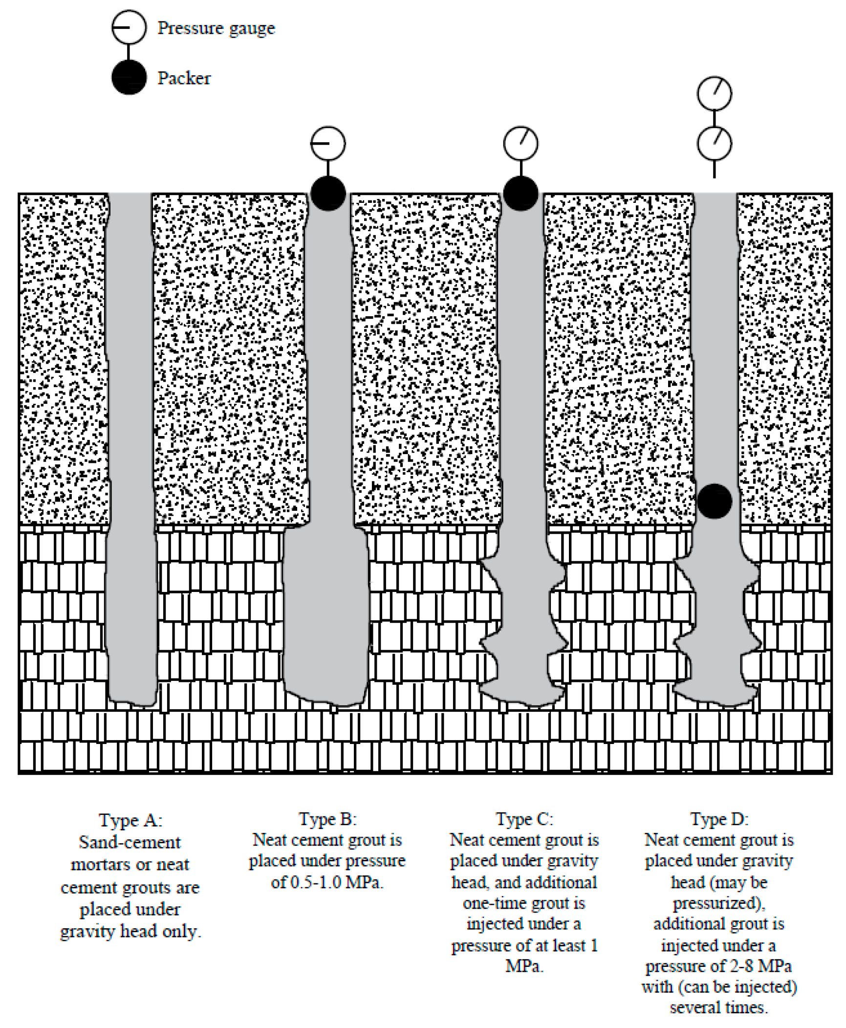
Figure 5.
Soil–MPs–structure response with different inclination angles (compilation after [13]).
Figure 5.
Soil–MPs–structure response with different inclination angles (compilation after [13]).
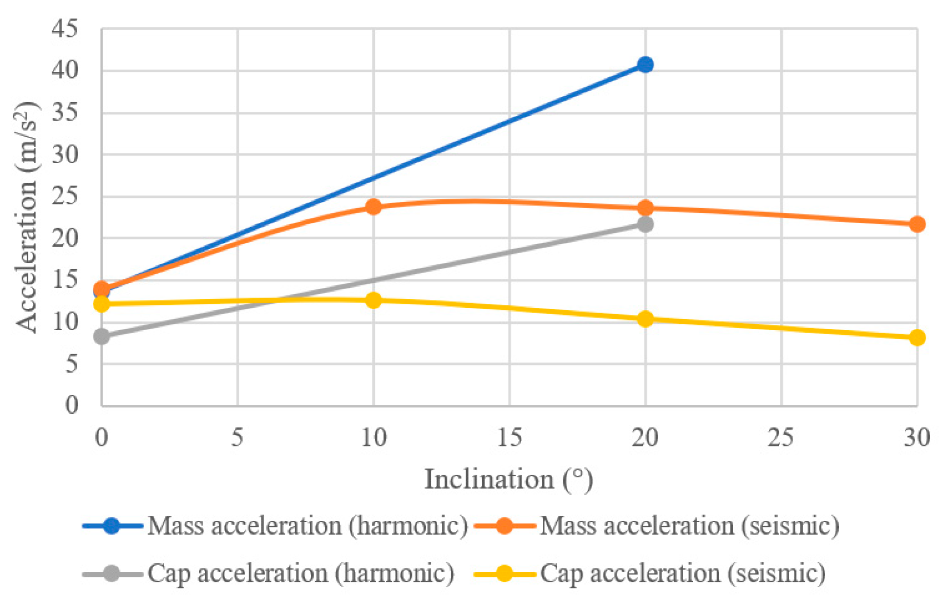
Figure 6.
Dynamic amplification factor with different fixity/inclination of MPs (compilation after [12]).
Figure 6.
Dynamic amplification factor with different fixity/inclination of MPs (compilation after [12]).

Figure 7.
MPs possible influence on the kinematic interaction due to the embedment depth (after [17,19,20]).

Figure 8.
Base isolator system attachment to concrete superstructure and substructure—typical detail (after [20,32,33]).
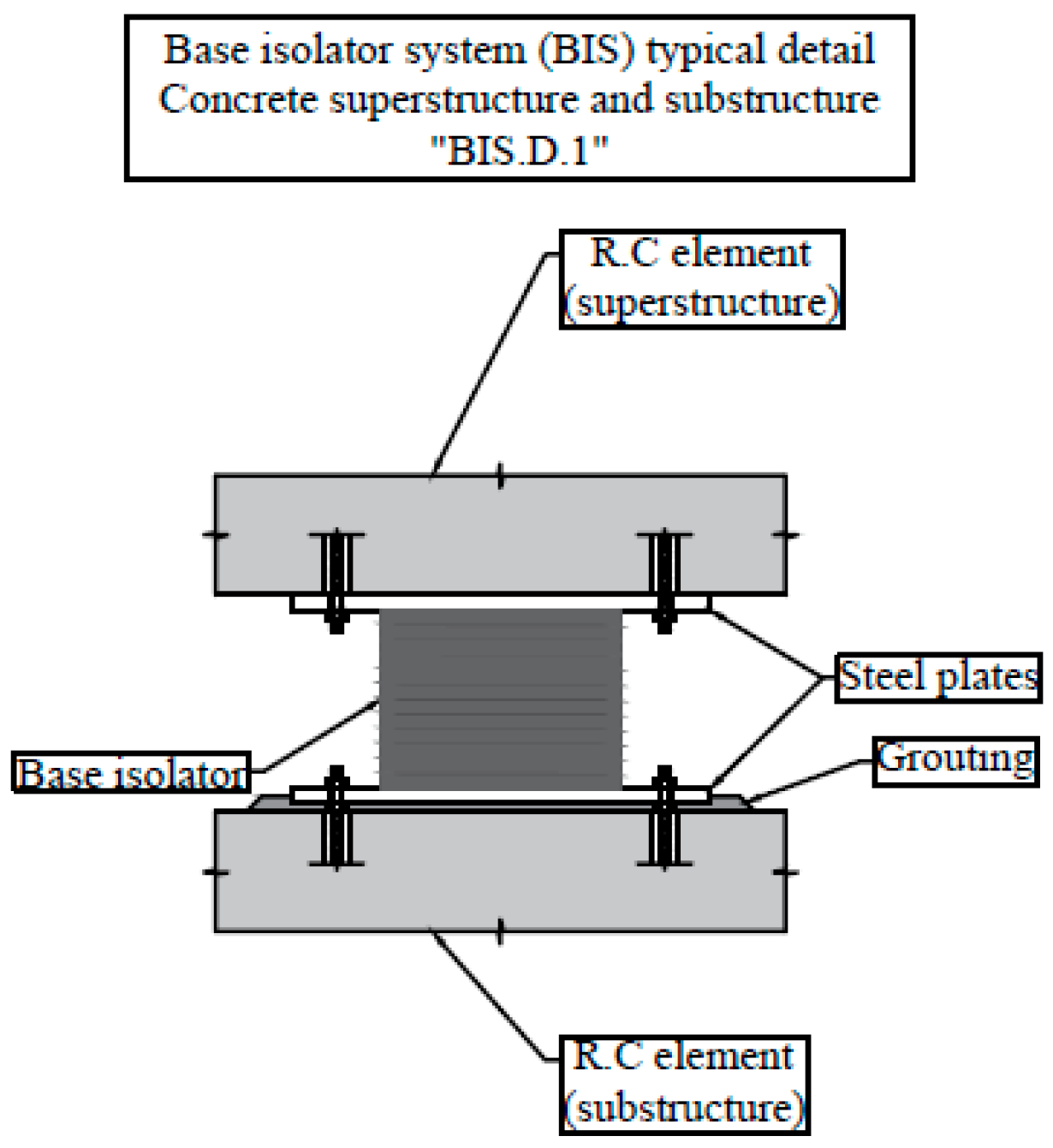
Figure 9.
Base isolator system attachment to steel superstructure and concrete substructure—typical detail (after [20,32,33]).

Figure 10.
Base isolator system attachment to steel superstructure and concrete substructure—typical detail (after [20,32,33]).
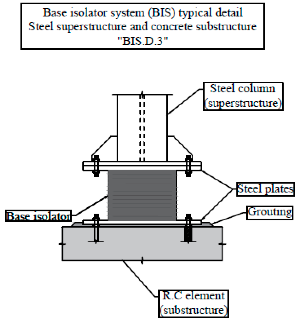
Figure 11.
MP connection to a new structure (new reinforced concrete footing)—typical detail (after [1]).
Figure 11.
MP connection to a new structure (new reinforced concrete footing)—typical detail (after [1]).
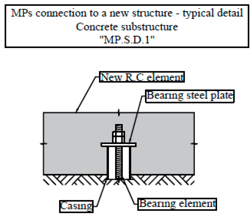
Figure 12.
MP connection to a new/existing structure (new/existing reinforced concrete footing)—typical detail (after [1]).
Figure 12.
MP connection to a new/existing structure (new/existing reinforced concrete footing)—typical detail (after [1]).
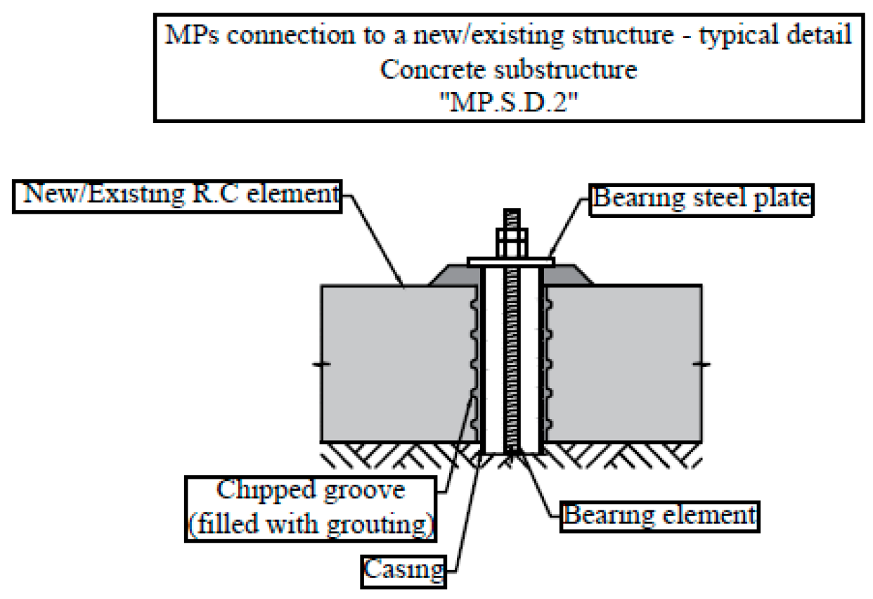
Figure 13.
MP connection to a new/existing steel base frame—typical detail (after [1]).
Figure 13.
MP connection to a new/existing steel base frame—typical detail (after [1]).

Figure 14.
New proposed detail for combing MPs with BIS (new reinforced concrete footing).
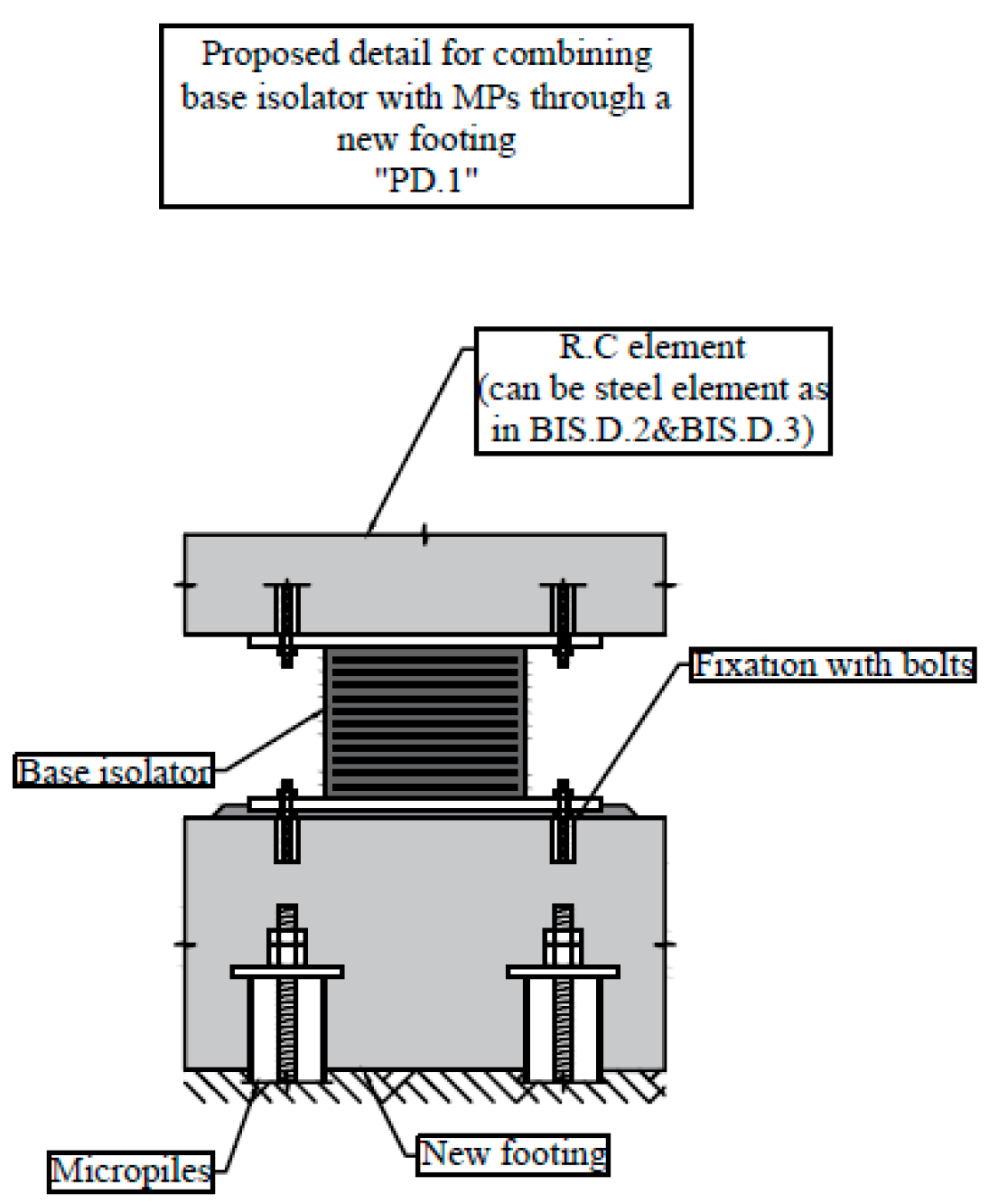
Figure 15.
New proposed detail for combing MPs with BIS (new/existing reinforced concrete footing).
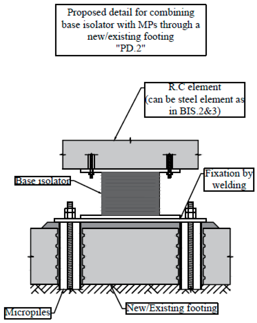
Figure 16.
New proposed detail for combing MPs with BIS (new/existing steel base frame).
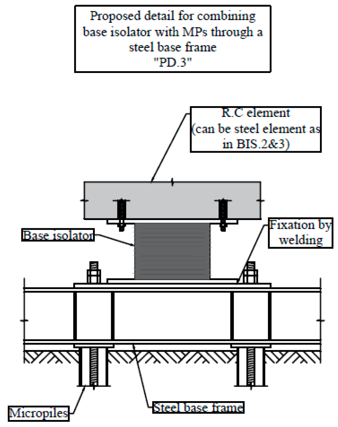
Figure 17.
General shear failure mechanism occurring in sand according to Terzaghi mechanism (after [38,43]).

Figure 18.
Punching shear failure mechanism occurring in clayey silt according to Terzaghi mechanism (after [38,43]).

Table 1.
Classification system of MPs after FHWA [1].
Table 1.
Classification system of MPs after FHWA [1].
| Design or Philosophy of Behavior | |||||
| Case 1 | Case 2 | ||||
| MP elements that are loaded directly (MPs main applicability is being a foundation system). This type of MPs is widely used and most of the applications and research activities were conducted with this type of MPs. | MPs elements are not loaded directly, but they create a theoretical composite soil–MPs base that resists the applied force (MPs main applicability is soil improvement). | ||||
| Construction or method of grouting (Figure 4) | |||||
| Type A | Type B | Type C | Type D | Type E * | |
| Grouting is placed under gravity head only. | Grouting is placed under the pressure of 0.5–1.0 MPa during the withdrawal of the temporary drill casing. | Step 1: Grouting is placed under gravity head only. Step 2: Additional one-time grout is injected under a pressure of at least 1 MPa. | Step 1: Grouting is placed under gravity head only or under pressure. Step 2: Additional grout is injected under a pressure of 2–8 MPa, the post-grouting can be done several times in several layers. | Continuous-thread hollow-core steel bars that are used to drill and to inject the grouting (self-drilling MPs). | |
* FHWA classification system recognizes four types only: A, B, C and D; the additional type E was added later by AASHTO [9].
Table 2.
Synthesis of factors and subfactors of influence for MP behavior (after [1,3,6,7,10,11,12,13,14]).
| Factor | Subfactors | Details |
|---|---|---|
| MP-related factors | Grouting | Material, pressure, technology, etc. |
| Bearing elements and Casing | Material, stiffness, etc. | |
| MP shape | Vertical, inclined, reticulated, uniform/nonuniform section, etc. | |
| Soil-related factors | Soil properties | Cohesive, cohesionless, density, etc. |
| Soil stratigraphy | Homogeneous, well-graded, weak soil overlying strong soil layer, etc. | |
| Soil dynamic properties | Influence on the seismic wave propagation | |
| MP-to-structure connection-related factors | Fixity condition | Between two extremes: fully fixed and fully pinned |
| Connection type | Concrete pile cap, steel plate, steel base | |
| Contact with soil | For example, in the case of pile cap, it can be fully embedded in soil, partially embedded, frictional contact, or with no contact | |
| Loading-related factors | Loading type | Axial, lateral, static, dynamic, complex, etc. |
| Loading intensity | Low, medium, and high (usually described in function of resulting strains) |
| Detail | Description | Advantages |
|---|---|---|
| PD.1 | Casting new footing to cover MPs and allow the installation of BIS | Typical detail for MPs and BIS |
| PD.2 | Installing MPs through an existing foundation (can also be used with a new foundation) and attaching the BIS on top of MPs bearing plate through welding | Can be used for new/existing structures |
| PD.3 | Installing MPs through a steel base frame (new or existing) and attaching the BIS on top of MPs bearing plate through welding | Can be used for new/existing structures; Relatively faster installation (no concrete pouring); Steel frame is easily adjusted |
Table 4.
Summary of selected papers concerning MP seismic behavior.
| Reference | Scope | Main Method | Remarks |
|---|---|---|---|
| [6,14] | Dynamic behavior of MPs with different grouting methods | Full scale experimental method (field study) | Grouting pressure has direct influence on the dynamic behavior (kinematic interaction) |
| [7] | Dynamic behavior of MPs in loose sand | Scaled experimental method (shaking table test) | Soil densification phenomenon; Effect on the kinematic and inertial interactions |
| [11] | Seismic performance of soil–MPs–superstructure | Numerical analysis (MC criterion) | Validated by a single-degree of freedom shaking table test; Parametric study with results illustrating the aspects of kinematic and inertial interaction |
| [12] | The influence of MP-to-structure connection | Numerical analysis (linear elastic) | Fixity condition influencing the dynamic amplification factor (inertial interaction) |
| [14] | Seismic performance of inclined MPs | Numerical analysis (MC criterion) | Not explicitly calibrated; Energy dissipation phenomenon (inertial interaction) |
| [15] | Effects of grouting technology on MPs behavior | Full scale experimental method (field study) | Grouting technology can enhance materials consumption, leading to stiffer MPs due to the reduction in the lost materials; Influence on both kinematic and inertial interactions |
| [16] | Load sharing between MPs and raft | Numerical analysis (MC criterion) | Influence on the inertial interaction |
| [35] | Soil plasticity influence in the analysis | Numerical analysis (MC criterion) | Influence on the inertial interaction |
| [36] | Performance of MPed rafts in sand | Scaled experimental method (centrifuge test) | Simulation of MPed raft behavior in sand with MC criterion; Calibrated with centrifuge test Influence on the inertial interaction. |
| [37] | Performance of MPed rafts in clay | Scaled experimental method (centrifuge test) | Simulation of MPed raft behavior in clay with MC criterion; Calibrated with centrifuge test; Influence on the inertial interaction |
| [38] | Installation methods influence on the failure mechanism | Scaled experimental method (model test) | MP confinement effect as a function of inclination angle; Influence on the kinematic interaction |
| [39] | Axial behavior of MPs | Full scale experimental method (field study) | Self-drilling MPs (type E) are the element of the study; Discusses the bond strength of this type of MP; Results can be used for calibration of numerical models; Inertial interaction |
| [40] | Influence of MPs stiffness on underpinning applications | Scaled experimental method (model test) | Compression of load sharing between waveform MPs and type-A MPs; Grouting pressure influencing the stiffness and MP behavior; Influence on the inertial interaction |
| [41] | Uplift capacity of MPs embedded in rocks | Scaled experimental method (model test) | Simulation of MPs behavior in rocks with MC criterion; Calibrated with model test; Influence on both kinematic and inertial interactions |
| [42] | Long-term consolidation | Numerical analysis (MCC criterion) | Calibrated with model test; MP efficiency in terms of long-term consolidation |
Table 5.
Factors influencing the seismic behavior—synthesis from literature.
| Factor | Importancy | Comments |
|---|---|---|
| Grouting | Grouting can modify the surrounding soil, which has a major influence on the kinematic and inertial interactions | Influence of gravitational and low pressure grouting (type A and B) have been studied with expermental and numerical methods [6,12,15]; More research on high pressure grouting needs to be carried out, some experimental data already exists; Calibrated numerical models of high pressure MPs might not be sufficient |
| Bearing elements and casing | Minor influence on the inertial interaction | Bearing elements and casing can help in providing stiffer MPs, which can influence the inertial interaction; Usually when studying MPs behavior, the MPs are treated as one composite element and the global behavior is concerned—more studies might be interesting in investigating the bearing elements role in the inertial interaction, not only by considering its influence on the stiffness, but also the influence on damping due to the plastificization of the steel components, cracks forming in the grouting body, and debonding that may occur due to an exccesive sesmic load [14,35]; Both experimental and advanced numerical analysis are needed. |
| MP shape | Influence on the inertial interaction by affecting the stiffness and on the kinematic interaction by modifying the soil | MP shape was mainly studied in terms of the influence on the inertial interaction by increasing the MP stiffness or modifying the inclination angle, especially for type A, B, and WF MPs—this was studied both experimentally and numerically [6,7,11,13,14,15,16,37,40]; The potential influence on the kinematic interaction, however, especially with high pressure grouting MPs, is not yet sufficiently studied; Additionally, the confinement effect due to MP inclination and installation method needs to be further investigated |
| MP-to-structure connection | Influence on the inertial interaction | The influence on the kinematic interaction is minor in this case; Numerical studies on the fixity condition exist in the linear elastic domain with perfect condition assumed (fully fixed/pinned), but taking into account the debonding phenomenon that might occur during high seismc events, research in this field needs more advancement [11,12,35]; This nonlinearity might have interesting application in the inertial interaction considering the influence on damping value |
Publisher’s Note: MDPI stays neutral with regard to jurisdictional claims in published maps and institutional affiliations. |
© 2022 by the authors. Licensee MDPI, Basel, Switzerland. This article is an open access article distributed under the terms and conditions of the Creative Commons Attribution (CC BY) license (https://creativecommons.org/licenses/by/4.0/).
Share and Cite
MDPI and ACS Style
Abou Alhaija, M.; Batali, L. Seismic Behavior of Micropiles and Micropiled Structures Used for Increasing Resilience: A Literature Review. Appl. Sci. 2022, 12, 2743. https://doi.org/10.3390/app12052743
AMA Style
Abou Alhaija M, Batali L. Seismic Behavior of Micropiles and Micropiled Structures Used for Increasing Resilience: A Literature Review. Applied Sciences. 2022; 12(5):2743. https://doi.org/10.3390/app12052743
Chicago/Turabian StyleAbou Alhaija, Majd, and Loretta Batali. 2022. "Seismic Behavior of Micropiles and Micropiled Structures Used for Increasing Resilience: A Literature Review" Applied Sciences 12, no. 5: 2743. https://doi.org/10.3390/app12052743
Note that from the first issue of 2016, this journal uses article numbers instead of page numbers. See further details here.