Article

Automation of the Edge Deburring Process and Analysis of the Impact of Selected Parameters on Forces and Moments Induced during the Process

1
Safran Aircraft Engines Poland, Południowa 23, 39-120 Sędziszów Małopolski, Poland
2
Faculty of Mechanical Engineering and Aeronautics, Rzeszow University of Technology, Aleja Powstancow Warszawy 8, 35-959 Rzeszow, Poland
*
Author to whom correspondence should be addressed.
Appl. Sci. 2023, 13(17), 9646; https://doi.org/10.3390/app13179646
Submission received: 17 July 2023 / Revised: 22 August 2023 / Accepted: 23 August 2023 / Published: 25 August 2023
(This article belongs to the Special Issue Advanced Manufacturing Technologies: Development and Prospect)

Abstract

:
The article concerns the possibility of the automation and robotization of the process of deburring jet engine components. The paper presents the construction of a laboratory stand enabling the automation of selected production operations of typical low-pressure turbine blades. The work identifies important parameters and results of the technological process related to the removal of burrs that affect the exactness of the process. The results of the analysis of the impact of individual process parameters on the magnitude of forces and moments occurring during deburring were carried out and presented. The results of initial and detailed tests were presented. Based on the results obtained, it was noticed that doubling the rotational speed of the brush results in a linear increase in torque and an increase in the engagement of the detail in the disc brush, leading to a non-linear increase in torque. It has also been shown that with tool wear, the value of the torque generated by the rotating tool decreases. Based on the results of a comparison of manual and automated process and histogram analysis, results from an automated stand are centered more correctly inside of the required radius range. This means that the repeatability of the process is higher for an automated test stand, which is one of the key aspects of large-scale aviation component manufacturing. Additionally, it was confirmed by visual inspection that all burs had been removed correctly—the deburring operation for all tested work pieces was successful. Based on the results obtained, it was proven that introduction of an automated stand can improve working conditions (by the elimination of the progressive fatigue of employees and the possibility for injury) and allows for the elimination of the negative impact of the machining process on workers. Further areas in which the optimization of the process parameters of the edge deburring can be developed in order to reduce unit costs have also been indicated.

1. Introduction

The production process of components used in aircraft engines is a complex and multi-stage operation. Starting with the production of a casting resembling a finished product, a ready component, e.g., a blade for a low pressure turbine, is prepared through a series of production operations such as grinding, thermal treatment, shot peening or locksmith operations. The multitude of production operations that are aimed at ensuring the appropriate performance properties translates into the time needed to produce the finished component, and thus the cost. Taking into consideration the economic conditions and the economic situation, companies operating in the aviation industry set the reduction in unit costs as one of their main goals, which enables them to compete in the aviation sector. This goal is achieved by reducing electricity consumption, reducing the number of tools used in the production process, and reducing the number of man-hours spent on the production of single components. One way to improve economic results by reducing costs directly related to production, and ensuring appropriate technological capabilities and repeatability, is through the automation of selected stages of production processes.
From the point of view of a company producing aviation components, the primary goal is to minimize operating costs, which translates into the economic parameters of the production process. Automation of the production process will enable wider control of the process by eliminating the impact of the human factor on the final product, and will also enable automatic control, which then allows for the optimization of the parameters of the brushing process, which will reduce production costs by reducing the time spent on the edge deburring process. In line with the above trend, research work was undertaken to robotize the brushing process and verify the impact of selected process parameters on the values of forces and moments. The main goal of the production process is to prepare components that meet specific design assumptions, such as defined dimensions, mechanical properties, or properly machined external edges. The condition of the outer edges has a direct impact on the durability and safety of component assembly. Therefore, it is important to remove all burrs and ensure the appropriate value of the radius of the outer edges of the work piece.
Burr is essentially a part of work material that has experienced plastic deformation owing to the compression exerted by the cutting tool but which ultimately failed to completely separate from the ductile workpiece [1]. Burrs limit the dimensional accuracy of the features, induce difficulty during assembly, prohibit sliding motion over the surface, and degrade its aesthetic value [2,3,4]. Burrs can also act as debris that accelerates wear and tear, resulting in the reduction in useful service life rendered by the components [5]. The research group of Dornfeld [6,7,8] also made extensive investigations to analytically model burr size, introducing the concept of the “negative shear plane”. Effects of various machining parameters such as cutting speed, feed rate [9,10,11,12,13], and cutting environment on burr formation have been studied in detail. Deburring, breaking sharp edges, or chamfering are the most common finishing operations performed in the aero-engine manufacturing sector [14,15]. Burrs and sharp edges are not allowed [16]. Other removal methods cannot be used, such as the physical and technical methods involving ultrasound, electrohydropulse processing, thermal energy, thermal pulse, electrochemical, and electrocontact methods [17,18]. Manual mechanical removal (or robotic mechanical removal if possible) is the only approved process.
An important point of view on the reliability and durability of parts included in a jet engine is the need to ensure the appropriate value of the edge deburring radius. This radius has a direct impact on the local stress level, and thus on the durability of the parts and the entire engine. The need to predict fatigue strength is the most important challenge for airlines and passengers using the services of the abovementioned companies [19], along with monitoring trends [20,21]. From the point of view of a manufacturer of aviation components, the main goal is to minimize operating costs, which refers to the economic parameters of the production process. The automation of the production process will enable much greater control by eliminating the impact of the human factor on the final condition of the product, and enabling the control and optimization of the parameters of the brushing process, which will reduce production costs by reducing the time spent on the edge deburring process.
Many studies have been written regarding work related to the implementation of industrial robots for machining operations. These studies clearly indicate a number of advantages thanks to the introduction of robotization, in the form of increased repeatability or cost reduction. Industrial robots have been successfully used for milling, deburring, polishing, or machining thin-walled elements [22].
In the scientific literature, a number of articles dealing with various methods of optimizing the deburring process can be found. Over the years, various approaches to achieving the desired machining accuracy have been described. In order to increase the accuracy of machining with the application of a robot, work was carried out to optimize the trajectory of the robot’s movement based on a dynamic model of the robot [23], as well as by real-time force control [24,25]. Laser trackers were used as an alternative to force control in order to track the required path of the robot, which led to an increase in machining accuracy [26]. Work was also carried out to optimize the deburring process in relation to the structural stiffness of the robot used [27]. The authors of [28] describe the process of optimizing the parameters in the process of belt grinding and deburring steel according to the surface roughness and material removal rate. Both indicators are considered, and experimental results have shown that the comprehensive target can be effectively used as a metric to control grinding performance and process improvement. In [29,30,31,32], the Taguchi design method was widely used to optimize the milling parameters for surface roughness. In [33], the authors presented and discussed the concept of the project of the sensor-less force control of automatic grinding and deburring through an adjustable mechanism. In [34,35], the authors show that the key to high-quality polishing and deburring is maintaining a constant contact stress between the grinding tool and the work piece. Excessive or insufficient clamping force significantly worsens the surface roughness. The study in [36] aims to provide insight into the development and evaluation of force-guided machining processes. The focus was on the deburring and grinding scenario. Deburring implements a force-dependent feed-rate control, while the grinding use case implements force (pressure) control. The authors of [37] indicate that controlling the clamping force on the work pieces is a difficult task in industrial deburring operations. To solve this problem, a constant force mechanism based on a combination of positive and negative stiffness mechanisms has been proposed.
The analyzed works clearly indicate the possible advantages related to the implementation of robots for individual production operations. Considering the multitude of studies, it was decided to prepare a laboratory stand in order to verify the feasibility of brushing the blades produced for the needs of modern jet engines. The analyzed works related to the optimization of the deburring process [23,24,25,26,27] indicate that in order to carry out the process of optimizing the brushing operation, it is necessary to determine the key parameters of the process and then to understand their mutual interaction. In addition, due to the unique pair of materials associated with each other (work piece material and brush material), it was necessary to carry out a number of tests to understand the interaction of process parameters, such as time, rotational speed, and brush infeed, with the work piece.
This article describes the preparation of a conceptual robotic station aimed at carrying out the edge deburring process with simultaneous control of the loads generated on the detail (blade) from the tool (brush) and the automatic verification of the edge condition after the process is completed. In the next section, a number of tests were carried out to examine the dependencies between the key parameters of the technological process (such as rotational speed, time of the process, or the depth to which the workpiece is moved to the rotating brush) and the forces generated during machining processing. In addition, blades from a jet engine low-pressure turbine are characterized by a complex shape and a multitude of edges, where for design reasons it is necessary to obtain the required value of edge rounding. Therefore, it was necessary to verify the results of the process automatically. The use of an automated device for the verification of the radius of edge rounding will increase the reliability of the process by eliminating the subjective assessment of the worker. The aforementioned visual inspection performed by a locksmith is subject to the possibility of human error. In conditions of high-volume production, taking measurements using a microscope with appropriate equipment significantly increases the cost of manufacturing work pieces. Keeping in mind the desire to reduce the unit costs of the manufactured components, it was decided to implement an in-process measuring device that would allow for the verification of the process results at any time.
The edge spinning process consists of bringing the manufactured work piece into contact with a rotating tool, such as a disc with bristles covered with abrasive material. As a result of the contact of the detail with the rotating disc, both the tool and the manufactured detail are worn at the point of contact with the mentioned objects. In the case that abrasion process takes place and the objects remain in contact with each other, it is possible to observe the interaction of the objects with each other through the creation of forces. In this paper, it was decided to examine how the parameters of the technological process affect the level of interaction between the detail and the tool. A small number of studies [38,39,40,41] have described in detail the relationship between the parameters of the technological process and the life of the tool. This is a key need, which is complemented by the subject matter taken up in the article. Requirements, such as improvement of working conditions, improvement of the company’s financial result, or control of the correctness of the locksmith operation, were the inspiration to take up the topic of developing the concept of an automated deburring station, and later to enable considerations related to the impact of parameters on the impact forces.

2. Problem Definition

In order to achieve the proper quality of the outer edges of the detail, i.e., to remove all burrs and obtain the appropriate radius of edge deburring, the work piece should be brought into proper contact with the rotating brush. The current way of carrying out the operation is shown in Figure 1. The operator uses his hands to bring the detail into contact with the rotating tool and thus performs the brushing process. As a result of contact and friction occurring between the tool and the work piece, burrs are removed and the edges are rounded.
The implementation of the brushing process with the direct participation of human operators in the process raises the following challenges, such as:
  • Lack of repeatability of the brushing process;
  • Lack of control of forces and moments occurring during the process (lack of objectivity), which prevents any work related to the optimization of tool wear;
  • Progressive fatigue of operators during the processing of subsequent pieces;
  • Costs of using appropriate individual and collective protective equipment, such as earmuffs and protective sleeves.
The lack of objectivity is directly related to the different pace of fatigue of individual operators or their different levels of rest at the time of starting work. This is a direct result of differences in the bodily makeup of individual operators, their psycho-physical condition, or their lifestyle. In connection with the conditions mentioned, before starting work related to the optimization of the edge deburring process, the concept of the workstation should first be developed. The stand should enable the measurement of the force between the detail and the tool and, furthermore, the verification of the impact of selected parameters on the mutual interaction of the detail and the tool.
The above actions are in line with the trend visible in the aviation industry, where efforts are made to minimize the number of expensive manual operations by automating and robotizing production processes. This approach is also in line with the ideas of Industry 4.0. Thanks to the implementation of industrial robots, the possibility of obtaining significantly greater repeatability and stability of technological process parameters for operations such as locksmithing or welding increases [42,43,44,45].

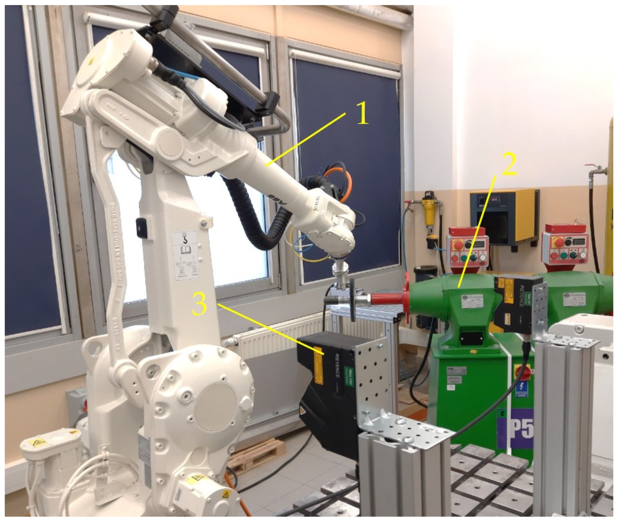
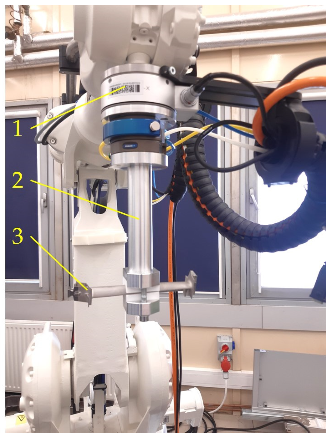
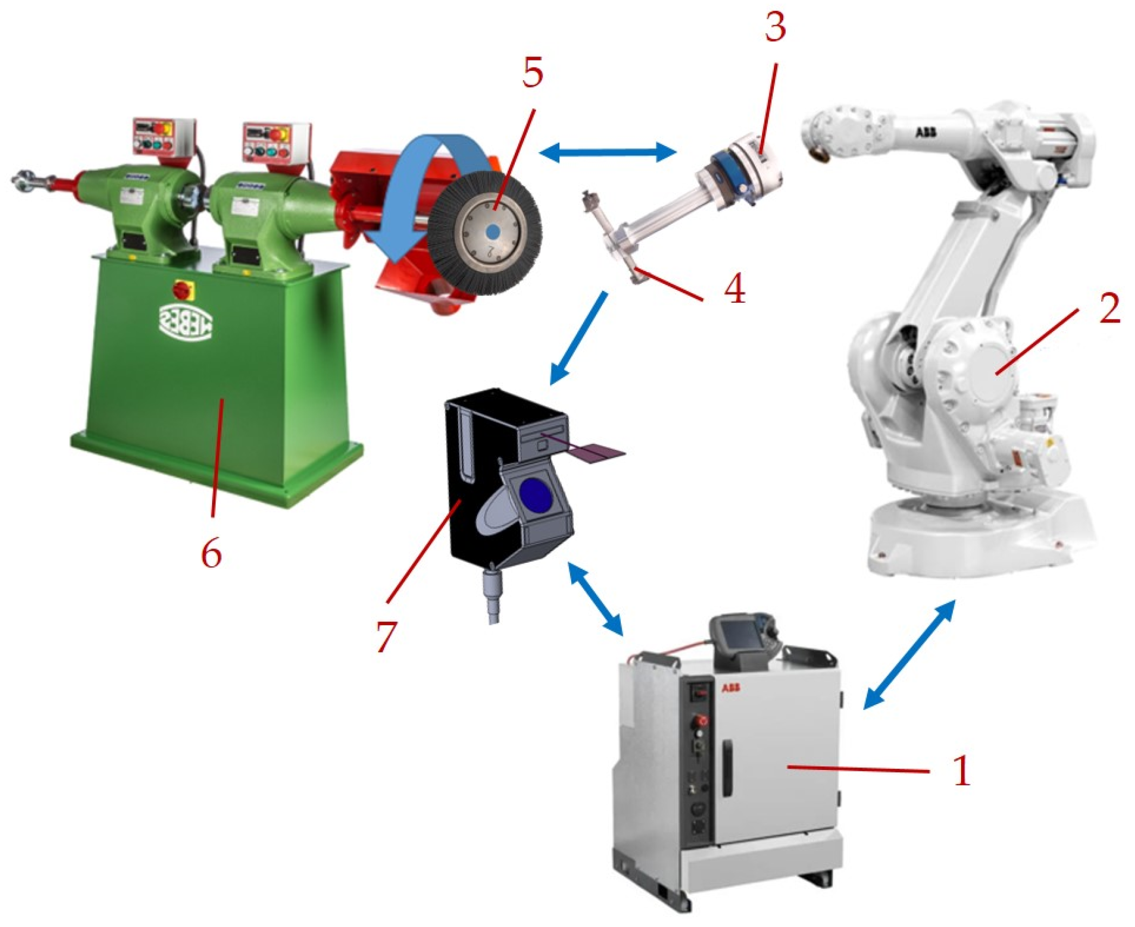
3. Solution—Test Stand

Due to the company’s desire to optimize production, it is necessary to carry out works aimed at the robotization and automation of locksmith operations occurring in the production process of blades. Therefore, actions were taken to verify the possibility of performing such an improvement and then to identify the key parameters of the technological process affecting the size of forces and moments occurring in the process. The research conducted was aimed at developing the assumptions necessary to launch an automatic station that performs the process of edge breaking and enabling the process of optimizing the parameters in terms of reducing the costs associated with the tools (brushes) used.
The work linked to the test workstation is intended to help gain the experience necessary to implement the desired solutions in industrial conditions, as well as verifying the relationship between parameters such as tool rotational speed and the depth of insertion of the work piece into the tool (brush), as well as the induced forces and moments during the analyzed operation.

3.1. Test Stand

In order to verify the possibility of conducting the process of breaking selected edges of low-pressure turbine blades in an automated manner, a dedicated test stand was prepared. The test stand was located in the laboratory of the Department of Applied Mechanics and Robotics of the Rzeszow University of Technology (Figure 2).
The following components were used to build the test stand:
  • ABB IRB 2400 industrial robot with ABB IRC5 controller and Force Control system;
  • An industrial grinder with a control system that allows one to change the rotational speed of the tool;
  • Keyence LJ-V7060 laser profilometer.
The ABB IRB 2400 robot is characterized by a maximum payload of 16 kg, a path repeatability of 0.15 mm, and a position repeatability of 0.03 mm. The aforementioned repeatability is very sufficient in relation to the process being carried out.
The laser profilometer is a sensor that enables 2D or 3D measurement (with additional equipment) of selected dimensions of the inspected object.
In the work, related to the preparation of the test stand, a KEYENCE LJ-V7060 device with the technical parameters presented in Table 1 was used.
An important feature, from the point of view of the aviation industry, is that the measuring device makes non-contact measurements. This is a key detail due to the fact that all kinds of defects may arise when the detail comes into contact with the measuring device, directly affecting the quality of the manufactured work pieces. An undoubted advantage of implementing such a solution is also the elimination of human error (the human factor) in activities related to making all kinds of measurements using various tools. In addition, the use of a pattern (reference detail) also does not eliminate the possibility of human error because it is the operator who compares the detail with the reference part. In the case that one uses this type of control, the final decision depends on the objective assessment of the operator and is also subject to error. Undoubtedly, the introduction of a laser profilometer to the workstation increases the perfection of the production process, and due to the shortening of the control time (the difference between the measurement or comparison made by a human and the use of a robotic station), it can have a positive impact on the unit cost of producing components. The laser profilometer has been installed in the working space of the industrial robot (Figure 2), and the measurement is carried out at a reference distance of 60 mm. In order to know the impact of individual key parameters of the technological process on the value of forces and moments occurring during the grinding process, it was necessary to use an appropriate sensor. The measurements were carried out using the Force Control Sensor 660, which is used in areas such as assembly, machining (e.g., grinding), and product testing. It is characterized by the following parameters (Figure 3).
This sensor makes it possible to adjust the TCP (tool center point) feed rate of the robot depending on the measured forces and moments during the process, which come from various machining parameters, e.g., the rotational speed of the tool. In practice, this means that the robot can modify the path or speed at which it moves to ensure that forces are maintained between the tool and the work piece. As the result of this functionality, the discussed sensor can be successfully used to control the deburring processes of elements with complex shapes, such as blades from a turbine engine. As a consequence, after using the Force Control sensor [46,47,48,49], it is possible to control the forces and moments generated during the grinding process, which has a direct impact on extending the life of the tools used in the process. The final result of these activities is an improvement in the company’s financial results. The tools used in the brushing process are disc brushes, made of a metal disc and bristles made of Abralon612 SiC material. The current consumption of brushes is about 6000–7000 pieces per year.
Figure 4 shows the Force Control sensor mounted on the robot’s arm with a handle and a detail.
The other device included in the prepared workstation is a brush used in the deburring process, mounted on an industrial grinder that has a built-in control system that allows it to control the tool rotation speed.

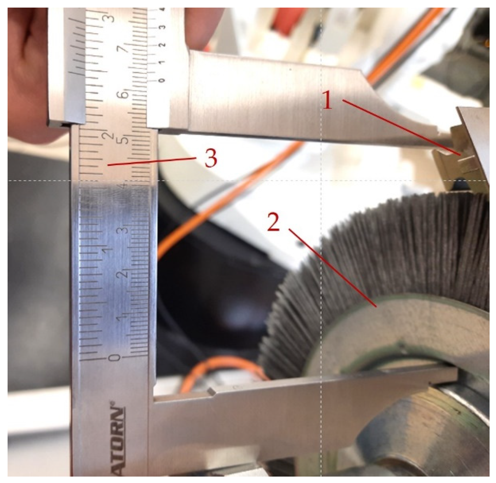
3.2. Identification of Key Process Parameters

Every production process is characterized by a significant number of variables and parameters, and their definition requires thorough familiarization with the construction and usage of the devices. To correctly assess the results obtained from individual operations, it is necessary to understand the technical requirements for the machined work piece. Before starting work on the automation of the deburring operation, an analysis of the process and station equipment was carried out. This made it possible to determine the parameters affecting the execution of the process. Parameters directly determining the result of the process were also identified. In this way, two groups of data were created, referred to as input data and output data. These data are presented in Table 2.

4. Tests

The deburring process carried out for the production of engine blades is aimed at achieving two results: removing burrs that are harmful during operation and giving the appropriate radius to all machined edges. Such action will guarantee the safety of the worker during turbine assembly and the safe operation of the entire engine during its life. In order to carry out the deburring process, the work piece being processed should be brought into contact with the rotating brush. During the tests (Figure 5), the work piece placed in the holder is moved by the robot along the programmed trajectory against the rotating brush mounted on the industrial grinder. Measurement values such as torque, force, and blunting radius are acquired by the force sensor and laser profileometer and then recorded in the database.
In order to carry out the correct brushing process, it is necessary to remove the burr and give the appropriate radius to all machined edges. For this purpose, it is necessary to prepare an appropriate sequence of movements of the work piece in relation to the brush. Based on the experience related to the implementation of the manual process, it was decided to copy the movements of the locksmith and program the manipulator in such a way that it would perform the movements of the locksmith as accurately as possible. The movements performed by the locksmith are presented in Figure 6.
In the manual process, the operator, after completing the first sequence shown schematically in the figure, rotates the work piece by 180 degrees and repeats the entire sequence. It was noticed during the tests that the mentioned sequence can be implemented more simply by changing the direction of rotation of the tool.
In the initial phase of the tests, the aim was to examine the values of forces and moments occurring during the process of edge deburring. For this purpose, a number of tests were carried out at different values of the rotational speed of the brush. In the end, two speeds were selected. For the initial test, it was decided to cover the potential maximum scope of the rotational speed. Based on experience from manual process, it was chosen to start from maximum rotational speed of brush used during manual deburring operation—1600 rpm. At higher speeds, the worker is unable to hold the work piece for the entire shift (great fatigue, pain in the wrists). As a maximum limit, for automated test stand tests it was decided to use 3000 rpm—this is maximum speed allowed by available industrial grinders. Data were recorded using the Force Control package [43,46,49,50]. Table 3 presents the observed differences between the initial state and the change in force and torque during the operation.
The results of the first trials, i.e., the values of the observed forces and moments, confirm the correctness of the sensor selection as they are within the measurement range according to the specification. Due to the negligibly small difference between the initial state and the forces obtained during the tests (a change of about 25% between the two rotational speeds used) in relation to the changes of moments (a change of about 130% between two used rotational speeds), it was decided to focus on the values of moments in further tests considered.
In the second stage of the tests, a number of tests were carried out (each test was repeated three times) aimed at verifying the moments occurring during the deburring process depending on the rotational speed of the tool and the depth of insertion of the work piece into the brush (Figure 7).
The results of the recorded values are presented in Table 4. The tests were carried out in two series. The first series included tests using a new (unused) brush. The second series of tests (Table 5) used a tool with a certain state of wear.
Figure 8 and Figure 9 show the results obtained for the two tested rotational speeds, with the torque value depending on the depth of insertion of the work piece into the tool and brush condition (new and used brushes).
The measurement of the edge radius using a laser profilometer (Figure 10) allowed for the verification of the correctness of the brushing process.
Edge break radius measurements for 30 different work pieces are shown in Table 6.
Based on the measurements carried out, the arithmetic mean was calculated according to the following dependence:
X ¯ = x 1 + x 2 + x 3 + x n n = 0.26   mm
and consequently the standard deviation according to the relationship:
a = ( x 1 X ¯ ) 2 + ( x 2 X ¯ ) 2 + + ( x n X ¯ ) 2 n = 0.027   mm
and the +/−3σ limits were calculated:
+ 3 σ = X ¯ + 3   ×   a = 0.34   mm
3 σ = X ¯ 3   ×   a = 0.18   mm
Obtaining the edges, characterized by an average radius of about 0.26 mm, proves the correctness of the deburring operation (design requirements have been met). In order to illustrate the obtained results in the form of the edge radius, a histogram (normal distribution) was prepared (Figure 11). From the design-requirement point of view, it is desire to obtain edge radius values in the range from 0.15 to 0.35 mm. The calculated limit of ±3σ stays within the limit defined by the design requirements. Based on the above automated process of deburring, this operation is adequate to meet the quality standards of the aviation industry.
To prepare a histogram, a population of 30 measurements was used. Parts were prepared with different process parameters (different values of the rotational speed of the tool, different values of the detail depth in the tool).
To compare the results of the automatic process, radius measurements for 30 random details with deburring performed manually are presented in Table 7.
Based on the measurements carried out, the arithmetic mean was calculated according to the following dependence:
X ¯ 1 = x 1 + x 2 + x 3 + x n n = 0.16   mm
and consequently the standard deviation according to the relationship:
a 1 = ( x 1 X ¯ ) 2 + ( x 2 X ¯ ) 2 + + ( x n X ¯ ) 2 n = 0.058   mm
and the +/−3σ limits were calculated:
+ 3 σ = X ¯ 1 + 3   ×   a 1 = 0.34   mm
3 σ = X ¯ 1 3   ×   a 1 = 0.02   mm
In order to illustrate the obtained results in the form of an edge radius, a histogram (normal distribution) was prepared as a result of the manual process (Figure 12).
The typical work-piece condition is presented on Figure 13. The left side represents a work piece with sharp edges and burrs present—i.e., the work piece immediately after the grinding operation. The right side of Figure 13 represents the typical condition of a work piece after the deburring process is performed on a built automated test stand.

5. Discussion

Based on the calculations of the standard deviation and the average, it can be predicted that the radius value will be, in the vast majority of cases, in the range from 0.18 to 0.34 mm (range +/−3σ). From the point of view of design requirements, these values are considered satisfactory. Based on experience related to the results of the manual process and histogram analysis, results from the automated stand are centered more correctly—the average value for the automated process is 0.26 mm, while for the manual process it is 0.16 mm.
We carried out a feasibility study of robotizing the process; the possibility of human error during the evaluation of the process results was eliminated, and the entire brushing process was carried out with minimal use of human force.
Based on the tests carried out and the results obtained, it can be stated:
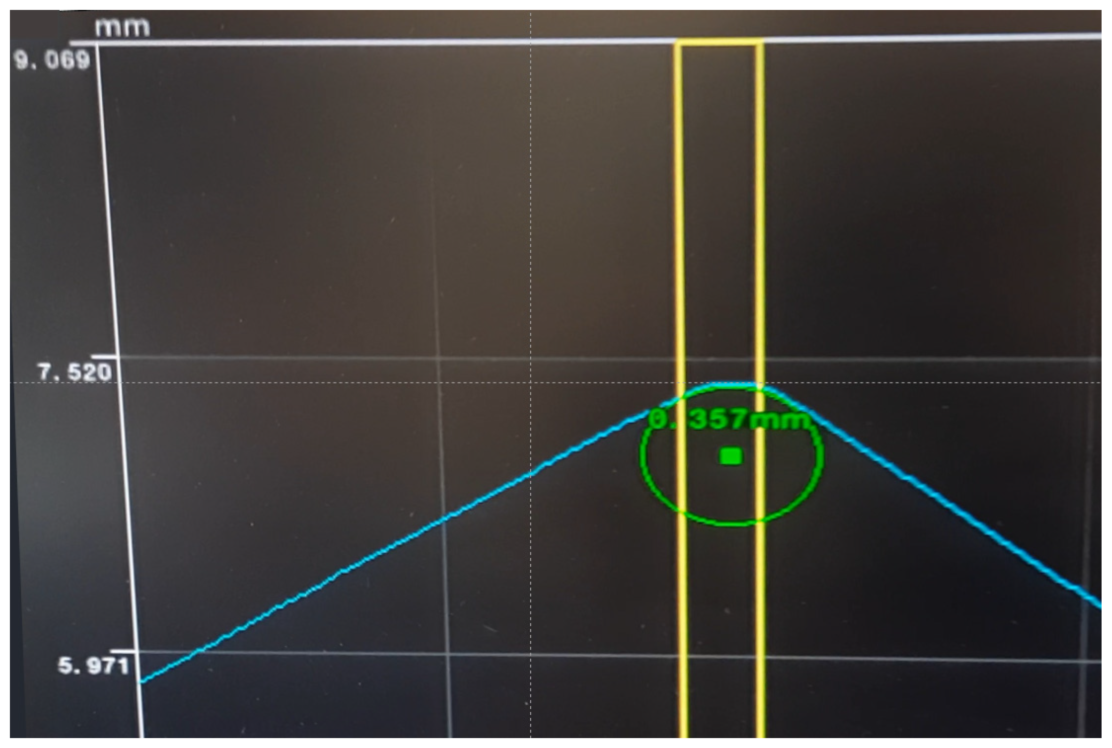
  • The deburring operation performed on built test stand was performed correctly—based on the observed work-piece condition, burrs were removed successfully—additionally, we created a histogram for the edge radius that confirms that the process is well centered;
  • The preparation of an automated stand eliminates a lot of challenges related to human factor, process stability and repeatability, and allows us to eliminate the process of operator fatigue;
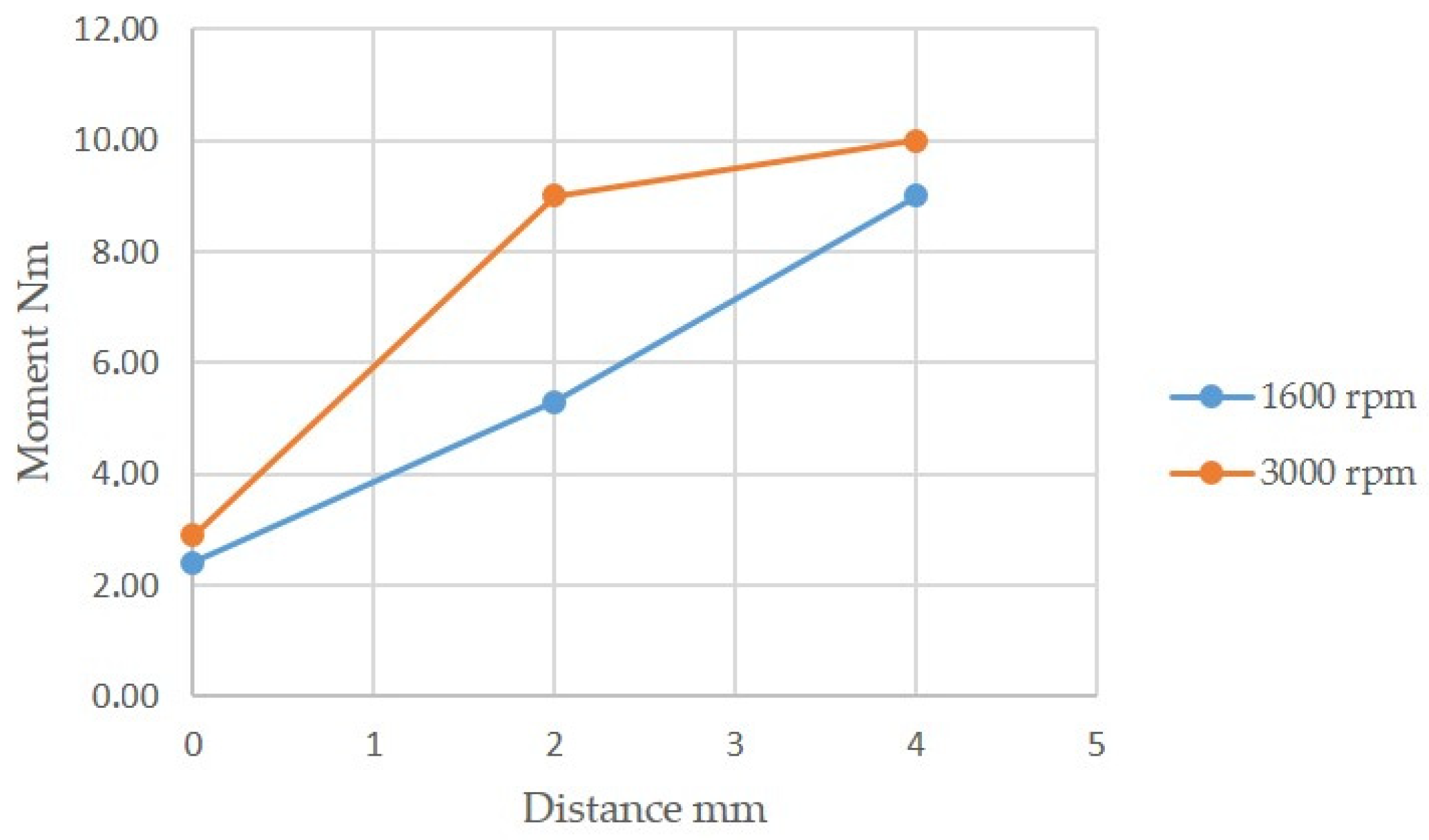
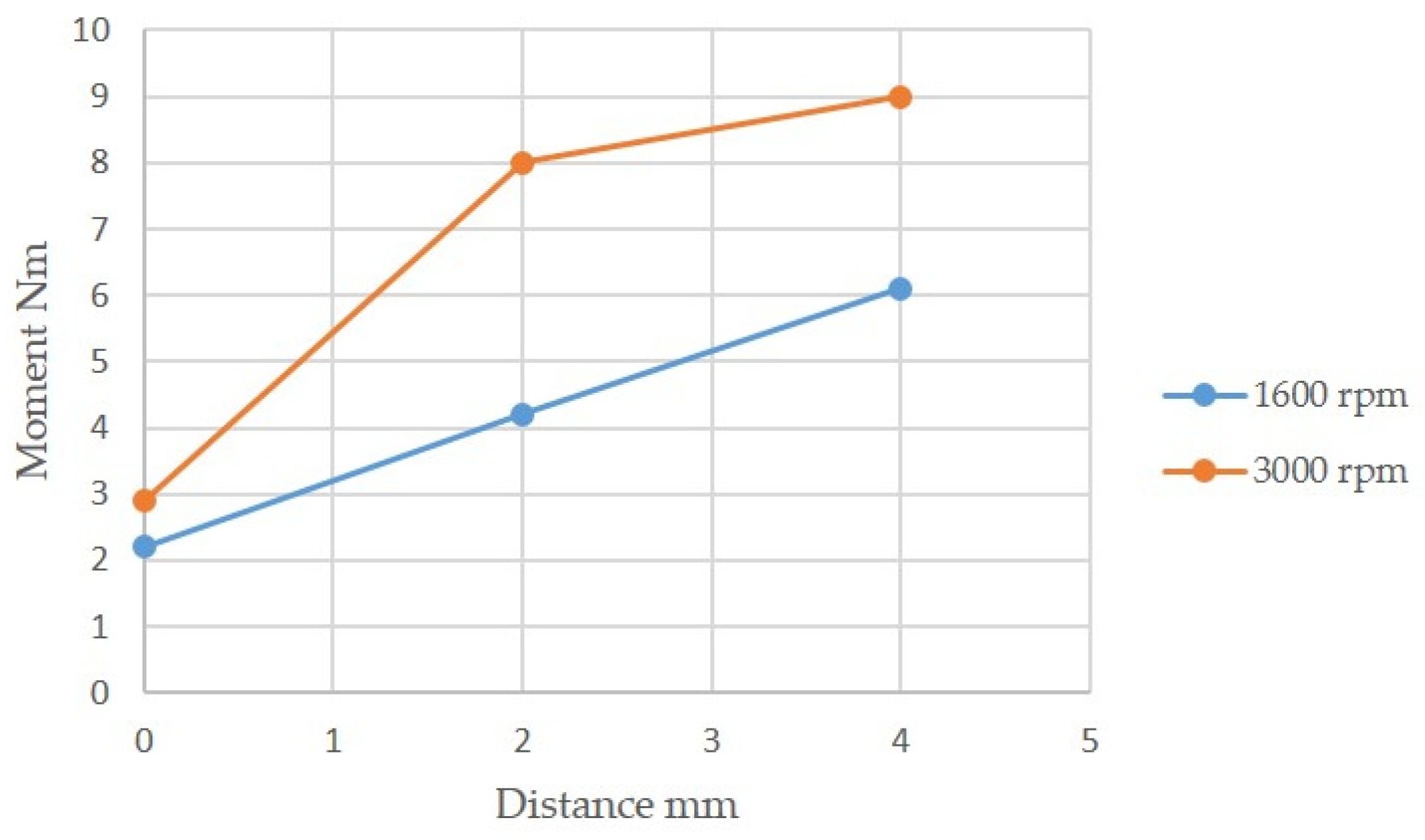
  • Doubling the rotational speed of the brush results in a linear increase in torque. The obtained results confirm that the above relation is correct for different rotational speeds;
  • Compared to manual processing, the operator (locksmith) was not able to work within the range of rotational speed tested. This is directly related to the physical endurance of a human, and directly translates into much faster wear of the brush in a manual process. In connection with these observations, it is important to introduce an industrial manipulator to the process in order to reduce tool wear;
  • The increase in the engagement of the detail in the disc brush leads to a non-linear increase in torque. The observed effect is much smaller at higher rotational speeds;
  • During the tests, tools that were not brand new were also used. Based on the tests carried out, it was observed that for the new disc, the measured moment during brushing was about 20% higher;
  • During all the tests carried out, burr removal was recorded in a way that meets the design requirements.

6. Conclusions

With reference to the obtained results, it can be concluded that the introduction of robotization to the deburring process will contribute to improving the working conditions of employees by eliminating harmful factors such as progressive fatigue or the possibility of injury. Based on the results obtained for 30 work pieces, it was shown that the large-scale introduction of robotization to the edge deburring process leads to an increase in the repeatability of results and improves the quality of the work pieces produced, significantly increasing safety during the use of devices containing brushed work pieces in the automatic process.
Based on the measurements, it can be concluded that the individual key parameters of the brushing process have a different impact on the load values. In the case of rotational speed, the influence is linear, i.e., the increase in rotational speed translates directly into an increase in loads. On the other hand, a change in the depth of insertion of the workpiece into the tool causes a non-linear increase in loads. It has also been shown that with tool wear, the value of the torque generated by the rotating tool decreases. In connection with the above, it is reasonable to carry out further work aimed at a selection of technological parameters that will lead to a reduction in tool wear in the technological process while meeting the design requirements for the blades.

Author Contributions

Conceptualization, A.B., D.S., K.F. and K.K.; methodology, K.F., K.K. and D.S.; software, A.B., D.S. and K.K.; validation, K.F., D.S. and K.K.; formal analysis, K.F. and A.B.; investigation, K.F., D.S. and K.K.; resources, A.B., K.K. and K.F.; data curation, D.S., K.K. and K.F.; writing—original draft preparation, A.B., D.S., K.K. and K.F.; writing—review and editing, K.K. and K.F.; visualization, K.K., K.F. and D.S.; supervision, A.B., K.K. and K.F.; project administration, A.B.; funding acquisition, A.B., K.K. and D.S. All authors have read and agreed to the published version of the manuscript.

Funding

This research received no external funding.

Institutional Review Board Statement

Not applicable.

Informed Consent Statement

Not applicable.

Data Availability Statement

Data are contained within the article.

Conflicts of Interest

The authors declare no conflict of interest.

References

  1. Hashimura, M.; Hassamontr, J.; Dornfeld, D.A. Effect of in-plane exit angle and rake angles on burr height and thickness in face milling operation. J. Manuf. Sci. Eng. 1999, 121, 13–19. [Google Scholar] [CrossRef]
  2. Mathai, G.; Melkote, S. Effect of process parameters on the rate of abrasive assisted brush deburring of microgrooves. Int. J. Mach. Tools Manuf. 2012, 57, 46–54. [Google Scholar] [CrossRef]
  3. Alagan, N.T.; Hoier, P.; Zeman, P.; Klement, U.; Beno, T.; Wretland, A. Effects of high-pressure cooling in the flank and rake faces of WC tool on the tool wear mechanism and process conditions in turning of alloy 718. Wear 2019, 434, 102922. [Google Scholar] [CrossRef]
  4. Saha, S.; Ansary, S.I.; Deb, S.; Bandyopadhyay, P.P. Influence of tool wear on chip-like burr formation during micro-milling, and image processing based measurement of inwardly-deflected burrs. Wear 2023, 530–531, 205024. [Google Scholar] [CrossRef]
  5. Niknam, S.A.; Songmene, V. Milling burr formation, modeling and control: A review. Proc. Inst. Mech. Eng. Part B J. Eng. Manuf. 2015, 229, 893–909. [Google Scholar] [CrossRef]
  6. Ko, S.L.; Dornfeld, D.A. A study on burr formation mechanism. J. Eng. Mater. Technol. 1991, 113, 75–87. [Google Scholar] [CrossRef]
  7. Chern, G.L.; Dornfeld, D.A. Burr/breakout model development and experimental verification. J. Eng. Mater. Technol. 1996, 118, 201–206. [Google Scholar] [CrossRef]
  8. Hashimura, M.; Chang, Y.P.; Dornfeld, D. Analysis of burr formation mechanism in orthogonal cutting. J. Manuf. Sci. Eng. 1999, 121, 1–7. [Google Scholar] [CrossRef]
  9. Gaitonde, V.N.; Karnik, S.R.; Achyutha, B.T.; Siddeswarappa, B. Methodology of Taguchi optimization for multi-objective drilling problem to minimize burr size. Int. J. Adv. Manuf. Technol. 2007, 34, 1–8. [Google Scholar] [CrossRef]
  10. Dhanke, V.D.; Phafat, N.G.; Deshmukh, S.D. Multi response optimization of process parameters in drilling of AISI 1015 steel for exit burr using combined PCA and grey relational analysis. Int. J. Mech. Prod. Eng. Res. Dev 2013, 3, 91–98. [Google Scholar]
  11. Kilickap, E.; Huseyinoglu, M.; Yardimeden, A. Optimization of drilling parameters on surface roughness in drilling of AISI 1045 using response surface methodology and genetic algorithm. Int. J. Adv. Manuf. Technol. 2011, 52, 79–88. [Google Scholar] [CrossRef]
  12. Singh, H.; Kamboj, A.; Kumar, S. Multi response optimization in drilling Al6063/SiC/15% metal matrix composite. Int. J. Chem. Nucl. Mater. Met. Eng. 2014, 8, 281–286. [Google Scholar]
  13. Raj, A.M.; Das, S.L.; Palanikumar, K. Influence of drill geometry on surface roughness in drilling of Al/SiC/Gr hybrid metal matrix composite. Indian J. Sci. Technol. 2013, 6, 5002–5007. [Google Scholar] [CrossRef]
  14. Ramachandran, N.; Pande, S.S.; Ramakrishnan, N. The role of deburring in manufacturing: A state-of-the-art survey. J. Mater. Process. Technol. 1994, 44, 1–13. [Google Scholar] [CrossRef]
  15. Thakre, A.A.; Soni, S. Modeling of burr size in drilling of aluminum silicon carbide composites using response surface methodology. Eng. Sci. Technol. Int. J. 2016, 19, 1199–1205. [Google Scholar] [CrossRef]
  16. STD-01. WBTC. Draft. Kansas City, MO: Deburring Technology International. Gillespie, LaRoux, K., Ed. 1996. “Burr and Edge Terminology: Definitions.” WBTC-STD 01. Draft. Available online: https://www.larouxgillespie.com/burrhist.pdf (accessed on 16 July 2023).
  17. Karlina, Y.I. Improvement of the technological process of processing parts of coaxial radio components using thermal impulse deburring. J. Phys. Conf. Ser. 2021, 2032, 012066. [Google Scholar] [CrossRef]
  18. Martyushev, N.V.; Bublik, D.A.; Kukartsev, V.V.; Tynchenko, V.S.; Klyuev, R.V.; Tynchenko, Y.A.; Karlina, Y.I. Provision of Rational Parameters for the Turning Mode of Small-Sized Parts Made of the 29 NK Alloy and Beryllium Bronze for Subsequent Thermal Pulse Deburring. Materials 2023, 16, 3490. [Google Scholar] [CrossRef]
  19. Aircraft Accident Report—United Airlines Flight 232 McDonnell Douglas DC-10-10 Sioux Gateway Airport; National Transportation Safety Board: Sioux City, IA, USA, 1989.
  20. Śliwa, R.E.; Dymora, P.; Mazurek, M.; Kowal, B.; Jurek, M.; Kordos, D.; Rogalski, T.; Flaszynski, P.; Doerffer, P.; Doerffer, K.; et al. The Latest Advances in Wireless Communication in Aviation, Wind Turbines and Bridges. Inventions 2022, 7, 18. [Google Scholar] [CrossRef]
  21. Rzucidło, P.; Jaromi, G.; Kapuściński, T.; Kordos, D.; Rogalski, T.; Szczerba, P. In-Flight Tests of Intruder Detection Vision System. Sensors 2021, 21, 7360. [Google Scholar] [CrossRef]
  22. Verl, A.; Valente, A.; Melkote, S.; Brecher, C.; Ozturk, E.; Tunc, L.T. Robots in machining. CIRP Ann. 2019, 68, 799–822. [Google Scholar] [CrossRef]
  23. Abele, E.; Bauer, J.; Rothenbücher, S.; Stelzer, M.; Von Stryk, O. Prediction of the Tool Displacement by Coupled Models of The Compliant Industrial Robot and The Milling Process. In Proceedings of the International Conference on Process Machine Interactions, Technische Universität Darmstadt, Berlin, Germany, 3–4 September 2008; pp. 223–230. [Google Scholar]
  24. Sörnmo, O.; Olofsson, B.; Robertsson, A.; Johansson, R. Increasing time-efficiency and accuracy of robotic machining processes using model-based adaptive force control. IFAC Proc. Vol. 2012, 45, 543–548. [Google Scholar] [CrossRef]
  25. Lehmann, C.; Halbauer, M.; Euhus, D.; Overbeck, D. Milling with Industrial Robots: Strategies to Reduce and Compensate Process Force Induced Accuracy Influences. In Proceedings of the 2012 IEEE 17th International Conference on Emerging Technologies & Factory Automation (ETFA 2012), Krakow, Poland, 17–21 September 2012; pp. 1–4. [Google Scholar] [CrossRef]
  26. Moeller, C.; Schmidt, H.C.; Koch, P.; Boehlmann, C.; Kothe, S.; Wollnack, J.; Hintze, W. Real Time Pose Control of an Industrial Robotic System for Machining of Large Scale Components in Aerospace Industry Using Laser Tracker System. SAE Int. J. Aerosp. 2017, 10, 100–108. [Google Scholar] [CrossRef]
  27. Gotlih, J.; Brezocnik, M.; Karner, T. Stiffness-Based Cell Setup Optimization for Robotic Deburring with a Rotary Table. Appl. Sci. 2021, 11, 8213. [Google Scholar] [CrossRef]
  28. Li, F.; Xue, Y.; Zhang, Z.; Song, W.; Xiang, J. Optimization of Grinding Parameters for the Workpiece Surface and Material Removal Rate in the Belt Grinding Process for Polishing and Deburring of 45 Steel. Appl. Sci. 2020, 10, 6314. [Google Scholar] [CrossRef]
  29. Abdur-RASHEED, A.; Konneh, M. Optimization of Precision Grinding Parameters of Silicon for Surface Roughness Based on Taguchi Method. Adv. Mater. Res. 2011, 264, 997–1002. [Google Scholar] [CrossRef]
  30. Zheng, X.F.; Yuan, J.L.; Wen, D.H. Parameters optimization on the lapping process of 9Cr18 with Taguchi method. Key Eng. Mater. 2008, 359, 158–161. [Google Scholar] [CrossRef]
  31. Yuan, J.L.; Lv, B.H.; Zhou, Z.Z. Parameters optimization on the lapping process for advanced ceramics by applying Taguchi method. Mater. Sci. Forum 2006, 532, 488–491. [Google Scholar] [CrossRef]
  32. Guven, O. Application of the Taguchi method for parameter optimization of the surface grinding process. Mater. Test. 2015, 57, 43–48. [Google Scholar] [CrossRef]
  33. Kuo, Y.L.; Huang, S.Y.; Lan, C.C. Sensorless Force Control of Automated Grinding/Deburring Using an Adjustable Force Regulation Mechanism. In Proceedings of the 2019 International Conference on Robotics and Automation (ICRA), Montreal, QC, Canada, 20–24 May 2019; pp. 9489–9495. [Google Scholar] [CrossRef]
  34. Liao, L.; Xi, F.J.; Liu, K. Modeling and control of automated polishing/deburring process using a dual-purpose compliant toolhead. Int. J. Mach. Tools Manuf. 2008, 48, 1454–1463. [Google Scholar] [CrossRef]
  35. Tsai, M.J.; Huang, J.F.; Kao, W.L. Robotic polishing of precision molds with uniform material removal control. Int. J. Mach. Tools Manuf. 2009, 49, 885–895. [Google Scholar] [CrossRef]
  36. Domroes, F.; Krewet, C.; Kuhlenkoetter, B. Application and analysis of force control strategies to deburring and grinding. Mod. Mech. Eng. 2013, 3, 11–18. [Google Scholar] [CrossRef]
  37. Ding, B.; Zhao, J.; Li, Y. Design of a spatial constant-force end-effector for polishing/deburring operations. Int. J. Adv. Manuf. Technol. 2021, 116, 3507–3515. [Google Scholar] [CrossRef]
  38. Muszyńska, M.; Burghardt, A.; Kurc, K.; Szybicki, D.; Szczęch, T. Monitoring the Parameters of the Robot-Operated Quality Control Process. Adv. Sci. Technol. Res. J. 2017, 11, 232–236. [Google Scholar] [CrossRef]
  39. Ramsauer, C.; Oswald, R.; Schörghofer, P.; Leder, N.; Schmitz, T.; Bleicher, F. Primary testing of an instrumented tool holder for brush deburring of milled workpieces. J. Mach. Eng. 2022, 22, 99–107. [Google Scholar] [CrossRef]
  40. Rodríguez, A.; Fernández, A.; López de Lacalle, L.N.; Sastoque Pinilla, L. Flexible Abrasive Tools for the Deburring and Finishing of Holes in Superalloys. J. Manuf. Mater. Process. 2018, 2, 82. [Google Scholar] [CrossRef]
  41. Uhlmann, E.; Hoyer, A. Modeling of Contact Forces for Brushing Tools. Ceramics 2021, 4, 397–407. [Google Scholar] [CrossRef]
  42. Caggiano, A.; Teti, R. Digital factory technologies for robotic automation and enhanced manufacturing cell design. Cogent Eng. 2018, 5, 1426676. [Google Scholar] [CrossRef]
  43. Burghardt, A.; Szybicki, D.; Gierlak, P.; Kurc, K.; Muszyńska, M. Robotic Grinding Process of Turboprop Engine Compressor Blades with Active Selection of Contact Force. Teh. Vjesn. 2022, 29, 15–22. [Google Scholar] [CrossRef]
  44. Kurc, K.; Burghardt, A.; Gierlak, P.; Muszyńska, M.; Szybicki, D.; Ornat, A.; Uliasz, M. Application of a 3D Scanner in Robotic Measurement of Aviation Components. Electronics 2022, 11, 3216. [Google Scholar] [CrossRef]
  45. Zhao, X.; Lu, H.; Yu, W.; Tao, B.; Ding, H. Robotic grinding process monitoring by vibration signal based on LSTM method. IEEE Trans. Instrum. Meas. 2022, 71, 1–10. [Google Scholar] [CrossRef]
  46. Burghardt, A.; Gierlak, P.; Kurc, K.; Szybicki, D. Automatic Detection of Industrial Robot Tool Damage Based on Force Measurement. Teh. Vjesn. 2020, 27, 1385–1393. [Google Scholar] [CrossRef]
  47. Villani, L.; De Schutter, J. Force Control. In Springer Handbook of Robotics; Siciliano, B., Khatib, O., Eds.; Springer: Cham, Switzerland, 2016; pp. 195–220. [Google Scholar] [CrossRef]
  48. Pires, J.N.; Afonso, G.; Estrela, N. Force control experiments for industrial applications: A test case using an industrial de-burring example. Assem. Autom. 2007, 27, 148–156. [Google Scholar] [CrossRef]
  49. Szybicki, D.; Burghardt, A.; Kurc, K.; Pietruś, P. Calibration and verification of an original module measuring turbojet en-gine blades geometric parameters. Arch. Mech. Eng. 2019, 66, 97–109. [Google Scholar] [CrossRef]
  50. Bilancia, P.; Schmidt, J.; Raffaeli, R.; Peruzzini, M.; Pellicciari, M. An Overview of Industrial Robots Control and Programming Approaches. Appl. Sci. 2023, 13, 2582. [Google Scholar] [CrossRef]
Figure 1. An operator during the deburring process (1—detail, 2—rotating tool).
Applsci 13 09646 g001
Figure 2. Test stand (1—industrial robot, 2—industrial grinder, 3—laser profilometer).
Applsci 13 09646 g002
Figure 3. Technical data of the applied force sensor.
Applsci 13 09646 g003
Figure 4. Force sensor mounted on the manipulator (1—Force Control sensor, 2—griper, 3—detail).
Applsci 13 09646 g004
Figure 5. Test stand (1—controller ABB IRC5, 2—industrial robot ABB IRB 2400, 3—Force Control, 4—work piece, 5—tool, 6—industrial grinder, 7—laser profilometer).
Applsci 13 09646 g005
Figure 6. Schematic of piece movement during brushing operation.
Applsci 13 09646 g006
Figure 7. Measurement of inserting the detail into the tool (1—work piece, 2—tool, 3—measurement).
Applsci 13 09646 g007
Figure 8. Dependence of the moment on the depth of insertion of the detail into the tool for two rotational speeds, new brushes.
Applsci 13 09646 g008
Figure 9. Dependence of the moment on the depth of insertion of the detail into the tool for two rotational speeds using brushes.
Applsci 13 09646 g009
Figure 10. Results of deburring operations measured by a laser profilometer.
Applsci 13 09646 g010
Figure 11. Histogram—values of edge break radius resulting from the robotic process.
Applsci 13 09646 g011
Figure 12. Histogram—values of edge break radius resulted from the manual process.
Applsci 13 09646 g012
Figure 13. Typical work piece condition—before and after deburring operation.
Applsci 13 09646 g013
Table 1. Technical data of laser profilometer Keyence LJ-V7060.
ModelLJ-V7060
Reference distance60 mm
Measurement range+/−8 mm—z-axis
Repeatability0.4 µm
Temperature characteristic0.01% full scale/°C
Table 2. Input and output data for deburring process.
Input DataOutput Data
Tool rotational speed, rpmRadius of edge break, mm
Time of the operation, sAll burrs removed, yes/no
Depth of engage—tool and work piece, mm
Table 3. Results of initial test.
Brush Rotational
Speed, rpm
Time of Contact
Work Piece—Tool, s
Force Difference, NMoment Difference, Nm
16005305
300054011.5
Table 4. Test results—new brush.
Rotational Speed, rpmDepth of Engagement, mmAverage Value of Moment
during Deburring Process, Nm
16000 (“touch”)2.4
30000 (“touch”)2.9
160025.3
300029.0
160049.0
3000410.0
Table 5. Test results—used brush.
Rotational Speed, rpmDepth of Engagement, mmAverage Value of Moment during Deburring Process, Nm
16000 (“touch”)2.2
30000 (“touch”)2.9
160024.2
300028.0
160046.1
300049.0
Table 6. Edge break measurements for selected work pieces.
Measurement NumberEdge Break Value, mm
10.23
20.23
30.22
40.3
50.32
60.26
70.24
80.25
90.29
100.3
110.28
120.25
130.22
140.24
150.26
160.23
170.26
180.27
190.25
200.28
210.29
220.25
230.19
240.26
250.25
260.27
270.27
280.25
290.25
300.25
Table 7. Edge break measurements for selected work pieces—manual process.
Measurement NumberEdge Break Value, mm
10.11
20.34
30.31
40.11
50.18
60.14
70.13
80.19
90.20
100.13
110.16
120.12
130.12
140.25
150.19
160.11
170.15
180.10
190.15
200.17
210.13
220.13
230.24
240.13
250.16
260.15
270.11
280.13
290.21
300.10
Disclaimer/Publisher’s Note: The statements, opinions and data contained in all publications are solely those of the individual author(s) and contributor(s) and not of MDPI and/or the editor(s). MDPI and/or the editor(s) disclaim responsibility for any injury to people or property resulting from any ideas, methods, instructions or products referred to in the content.

