


Design of a Broadband Transition from a Coaxial Cable to a Reduced-Height Rectangular Waveguide


School of Electric and Computer Engineering, Chungbuk National University, Cheongju 28644, Republic of Korea
*
Authors to whom correspondence should be addressed.
Appl. Sci. 2023, 13(20), 11265; https://doi.org/10.3390/app132011265
Submission received: 14 September 2023
/
Revised: 29 September 2023
/
Accepted: 12 October 2023
/
Published: 13 October 2023
(This article belongs to the Topic Electronic Communications, IOT and Big Data)
Abstract
:For miniaturization, rectangular waveguides with a reduced height are often required, along with a coaxial transition for signal launching. We present a simulation-based design of a broadband transition from a coaxial cable to a rectangular waveguide with the height(b)-to-width(a) ratio b/a ranging from 0.125 to 0.375. The proposed transition consists of a coaxial probe with a cylindrical head or a disk and two symmetrically placed tuning posts. To extend the operating frequency range, three sections of the rectangular waveguide are employed with properly chosen dimensions. Design examples are presented for the WR75 waveguide transition with a b/a of 0.125, 0.25, and 0.375, having a bandwidth of 83.4%, 92.7%, and 84.4%, respectively. Compared with previous works, our design offers the largest bandwidth in a right-angle coaxial-to-rectangular waveguide transition employing the aforementioned structure.
1. Introduction
Coaxial-to-waveguide transitions (CWTs) are essential components in RF and microwave systems. CWTs are implemented to ensure impedance matching between the coaxial cable and various waveguides. This is because coaxial cables typically have an impedance of 50 Ω or 75 Ω, whereas the impedance of the waveguide will strongly be dependent on the waveguide’s physical dimensions and other electromagnetic properties, such as the waveguide’s propagating modes. As such, CWTs do not only serve as an impedance matching interface but also as a mode conversion device assuring the conversion of the coaxial signal mode, which is primarily transverse electromagnetic (TEM), to the dominant mode of the waveguide, or vice versa.
CWTs can be implemented using various methods and techniques, including the use of auxiliaries, such as irises, pins, and stubs. Such auxiliaries directly impact key performance parameters, including the voltage standing wave ratio (VSWR) and loss in the operational bandwidth. However, they can fall short when designing CWTs for applications requiring waveguides with a smaller footprint and reduced physical dimensions. This is the case for space communications systems that tend to have more stringent requirements for waveguide dimensions for wide and narrow walls. For example, these dimensions range from 23 to 120 mm for the wide wall and 5 to 10 mm for the narrow wall, as specified in the GOST 20900-2014 standard, which outlines copper and brass rectangular waveguide pipes.
More advanced design considerations are required for CWTs with reduced-height waveguides. This holds true as the need for compact cointegrated systems grows bigger [1]. The miniaturization of electronic components is leading to an increase in operating frequency range. More systems are being designed for operation at higher frequencies to take advantage of the available spectral bandwidth [2]. As the frequency increases, the physical dimensions of the components are reduced. This exacerbates the aperture difference between the coaxial cable and the waveguide. It is, therefore, crucial to design CWTs for a broadband operational bandwidth and a reduced waveguide height.
In view of the above observation, the purpose of this study was to design a right-angle coaxial-to-rectangular waveguide with a simple disk probe and two tuning posts. The design goal was to obtain record-breaking bandwidth with the aforementioned structure. To this end, we employed the bandwidth extension method of Cano and Mediavilla [3] and the wideband right-angle CWT structure of Bialkowski and coworkers [4]. The end result is a new wideband coaxial transition for reduced-height rectangular waveguides. In the following, we will describe the initial design and optimization of the proposed transition.
2. Review of Existing Work
Previously, Komarov and coworkers proposed a broadband CWT with a corner transition structure implemented between a coaxial line with an inner/outer radius of 1.52/3.50 mm and a rectangular waveguide with the narrow-to-wide wall ratio or the waveguide height(b)-to-width(a) ratio b/a of 5/35 [5]. The transition structure consisted of a rectangular waveguide with an input guide size of a × b = 35 mm × 8 mm and an output guide size of a × b = 35 mm × 5 mm, and a coaxial line terminated by a disk probe. The disk was directly connected to the inner conductor of a coaxial line that served as a probe. A rounded step was implemented in the rectangular waveguide to ensure a smooth transition between the input and the output waveguides and to reduce the possibility of electrical breakdown. This CWT achieved a reflection coefficient of less than −20.8 dB at 5.0–7.5 GHz. Another work by Liao and coworkers [6] implemented a similar structure for a transition with an input waveguide of a × b = 28.5 mm × 7.61 mm and an output waveguide of a × b = 28.5 mm × 5.5 mm. These dimensions of the reduced-height CWT were obtained by numerical optimization for a return loss of greater than 30 dB at 6.1–10.6 GHz.
A conically-coupled CWT was introduced by Kim and coworkers [7] for a reduced-height waveguide with a × b = 12.94 mm × 1.40 mm covering 14.5–18.5 GHz. In this work, the CWT was implemented using a conical probe, which was fed by a coaxial line with a microstrip line. The conical probe served as a stepped-transformer stub, ensuring a good impedance matching between a coaxial line and a reduced-height waveguide. Tuning the radius of the conical probe yielded optimum performance with a return loss of >20 dB at 14.5–18.5 GHz.
CWT transitions can vary depending on the structure of the waveguide. For example, the transition from a coaxial line to dielectric-filled waveguides would be more challenging. An airgap CWT configuration was implemented by Tian and coworkers [8] for a dielectric-filled waveguide with a small value for b/a. The coaxial probe’s diameter was increased gradually, followed by a tapered profile to reduce the input inductance. The airgap served as a capacitor to further reduce the input inductance. A return loss of >20 dB across 1.2–2.4 GHz was recorded using a conical probe in an 83 mm × 10 mm waveguide filled with a dielectric material of εr = 2.53.
In [9], Rizawa and coworkers proposed a CWT consisting of a rectangular-to-ridge waveguide transition and a ridge waveguide-to-coaxial transformer. The ridge width and height and the waveguide width and height were chosen to allow a uniform distribution of the electric field at the interface where a ridge waveguide comes into contact with a coaxial line. In the case of the coaxial-to-waveguide transformer, the inner conductor of the coaxial line was shorted to the wall of the waveguide through a taper. This work reported a return loss of greater than 10 dB at 0.70–2.50 GHz with a 250 mm × 25.4 mm waveguide.
Mallach and Musch [10] employed a tapered section of a double-ridge waveguide to achieve a right-angle coaxial-to-rectangular waveguide transition with a × b = 150 mm × 14 mm operating at 1.18–2.91 GHz with a return loss of 20 dB and a higher-order mode level of −24 dB. Hassan and coworkers [11] proposed a right-angle CWT with b/a = 0.5 operating at 1.47–2.56 GHz with a 15 dB return loss. They employed a printed coaxial probe and a shaped reflecting plate placed between the back short and the probe in their design.
In this work, we introduce a new broadband transition between a coaxial line and a reduced-height rectangular waveguide. We seek to further increase the operational bandwidth of the transition in comparison to previously reported works.
3. Design
In this communication, we present a simulation-based design method for a broadband CWT for reduced-height rectangular waveguides. This work is not an outcome of a research project which would warrant the fabrication and measurement of a prototype design. As such, the validation of the proposed concept was conducted through a computer simulation using CST Studio Suite, a well-known and accurate tool for EM simulation. We provide extensive details on the design of the proposed CWT so that the achieved results can be verified by anyone if needed.
Designs are presented for a coaxial-to-rectangular waveguide transition with a waveguide height(b)-to-width(a) ratio b/a ranging from 0.125 to 0.375 having a ratio bandwidth of >2.4 or, equivalently, a percent bandwidth of >82.4%. A transition’s bandwidth is determined from the frequency range f1 ≤ f ≤ f2, where the reflection coefficient is less than, for example, −20 dB, or the VSWR is less than 1.2. Then the ratio bandwidth is given by f2/f1 and the percent bandwidth by 200(f2 − f1)/(f2 + f1).
Figure 1 shows the structure of the proposed transition together with a rectangular coordinate system whose origin is at the lower left corner in the back short of the waveguide R1. Waveguide walls are assumed to be made of a perfect electric conductor, and the waveguide interior is filled with air. To implement the proposed CWT, we considered employing a tuning post in addition to a coaxial probe, as reported by Bialkowski and coworkers [4]. They analyzed and designed a coaxial-to-waveguide adaptor with a descended probe and a tuning post. The tuning post served as a short-circuited second probe and was used to tune the impedance matching. When the coaxial probe was positioned at the waveguide’s half-width position x = a/2, the TE20 mode was suppressed. Similar results were obtained with two tuning posts symmetrically placed in the x direction. Here, we leverage this technique to increase the bandwidth.
Figure 2 shows the detailed structure and dimensional parameters of the proposed transition. For a broader frequency range of operation, the starting frequency should be lowered and the upper frequency increased. To lower the starting frequency, we leveraged the Cano–Mediavilla technique for increased bandwidth, which achieved a bandwidth ratio of 2.0 [3]. In this method, a double-step conversion of the rectangular waveguide width is employed. This allows the transition to operate close to the TE10 mode cutoff of the output waveguide. In designing a wideband rectangular waveguide transition, it is important to check the cutoff frequencies of the higher-order modes as well as that of the dominant TE10 mode. The cutoff frequency fc and the guided wavelength λg of the TEmn/TMmn mode in an air-filled rectangular waveguide is given by
where c is the speed of light in vacuum, a is the broad-wall width, b is the narrow-wall height, and λ is the wavelength in vacuum.
fc = (c/2) [(m/a)2 + (n/b)2]1/2
λg = λ/[1 − (fc/f)2]1/2
Starting from the initial dimensions, we carried out a parametric analysis of the structure prior to the automatic optimization using CST Studio Suite. The output waveguide width a is the same as that of the WR75 standard waveguide (19.05 mm), and the output waveguide height b is 0.125a, 0.25a, and 0.375a. For these waveguide dimensions, the TE10 mode cutoff is at 7.87 GHz, and the TE11/TM11 mode cutoff in the output waveguide occurs at 63.45, 32.44, and 22.41 GHz for b = 0.125a, 0.25a, and 0.375a, respectively. The parameter L is the output WR75 waveguide length whose value does not affect the transition performance as long as it is large enough. A value of 15 mm or about 0.787a was used in all cases.
The width a1 of the first waveguide is set about 4% larger than the output waveguide width a so that its TE10 mode is cut off at 7.57 GHz. The height b1 of the first waveguide is set at a value 8% smaller than that of the output waveguide height b. In this case, the TE11/TM11 mode cutoff in the first waveguide occurs at 68.87, 35.10, and 24.13 GHz for b = 0.125a, 0.25a, and 0.375a, respectively. The width a4 and height h4 of the second waveguide are initially set at the average of those of the other two waveguides. The length L4 of the second waveguide is set at 0.3 times the output waveguide width a. One of the most critical dimensions is the probe location L1, whose initial value is set at 0.25a. The disk diameter D1 and height H1 are initially set at 0.10a and 0.50b and adjusted for a wideband operation. The dual tuning posts’ location L2 and S2, diameter D2, and height H2 are adjusted to reduce the reflection coefficient to a value less than −20 dB with their initial values set at 0.25a, 0.35a, 0.20a, and 0.25b, respectively.
In Table 1, we provided the initial values of the dimensional parameters normalized with the output waveguide width a or with the height b, depending on the parameter type. For the coaxial cable, we used an SMA connector with an outer conductor diameter 2b0 = 4.11 mm and an inner conductor diameter of 2a0 = 1.27 mm. PTFE material (εr = 2.08) fills the space between the inner and outer conductors of the coaxial line. The first higher-order TE11 mode cutoff occurs at 24.58 GHz in this coaxial line.
Figure 3 and Figure 4 show changes in the reflection coefficient of the transition due to variations in the disk probe and tuning post dimensions of the transition with b/a = 0.125. These figures can also serve as tolerance analysis results. We observe that the reflection coefficient is sensitive to disk height H1, the disk gap H0, the probe distance L1 from the back short, and the tuning post distance L2 from the disk probe.
After extensive parametric analyses, we set the parameters for the automatic optimization by the simulation tool: the range of dimensional parameter values, the operating frequency range, and the target reflection coefficient value. Out of the seven optimization techniques in the CST Studio Suite, such as ‘Genetic Algorithm’ and ‘Particle Swarm Optimization’, we found that the ‘Trust Region Framework’ was the most efficient and reliable for this problem. The number of simulations with the ‘Trust Region Framework’ optimization ranges roughly from 50 to 300.
Figure 5 shows the variation in the reflection coefficient during the optimization of the transition with b/a = 0.125. Figure 6 shows the electric and magnetic fields inside the transition with b/a = 0.375. Operation with well-matched impedance can be observed by noting that the maximum field is nearly uniform along the wave propagation path, resulting from the small value for the voltage standing wave ratio. Table 2 shows the dimensions of the optimized transitions with b/a ratios of 0.125, 0.250, and 0.375.
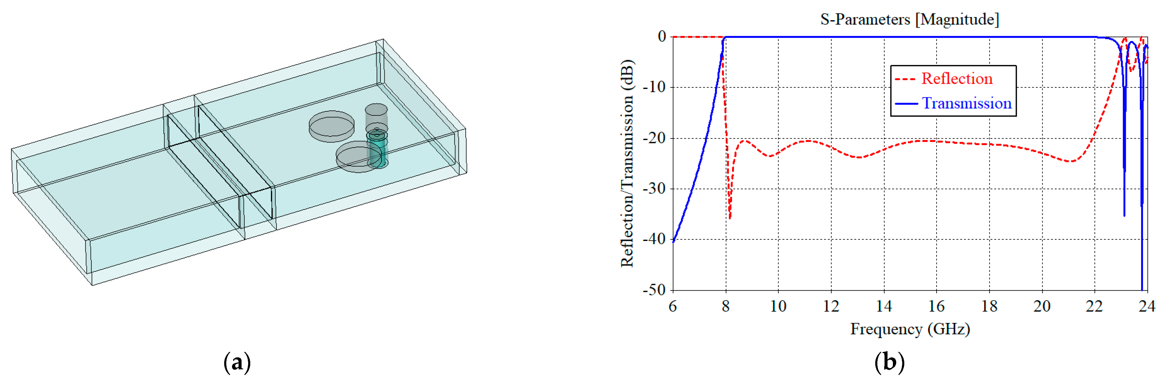
Figure 7a shows the structure and the simulation results of the proposed transition with b/a = 0.125. Figure 7b shows the reflection coefficient at the waveguide port with the TE10 mode and the transmission coefficient from the output waveguide TE10 mode port to the coaxial cable TEM port of the CWT. It can be seen that the reflection coefficient |S22| at the waveguide port is <−20 dB at 8.04–19.54 GHz. Without the loss in the transition, the transmission coefficient squared |S12|2 is given by 1 − |S22|2 from the law of energy conservation. The reflection coefficient |S11| at the coaxial cable port is almost identical to |S22| in the operating frequency range and, thus, is not drawn in Figure 7b.
Figure 8 shows the higher-order mode generation in the rectangular waveguide. It was obtained by assuming the output waveguide port is perfectly matched for all nonnegligible modes and by plotting the transmission coefficient from the coaxial cable TEM port to the waveguide TEmn and TMmn port. Only the transmission coefficients with an appreciable magnitude were included in Figure 8. At the transition’s operating frequency range of 8.04–19.54 GHz, the higher-order mode with the largest strength is the TE30 mode, having a transmission coefficient of −70.0 dB at 19.54 GHz. Due to the structural symmetry in the x direction, the generation of the TE20 mode is suppressed to an extremely low level and is not plotted in Figure 8. With a = 19.05 mm and b = 0.125a = 2.38 mm, the cutoff frequency of the first eight higher-order modes in the output waveguide is 15.74, 23.61, 31.47, 39.34, 62.96, 63.44, 64.89, and 67.23 GHz for TEmn/TMmn modes with mn = 20, 30, 40, 50, 01, 11, 21, and 31, respectively.
The results for the transition with b/a = 0.25 are shown in Figure 9 and Figure 10. Figure 9a shows the structure, and Figure 9b shows the reflection and transmission coefficients. The results show a reflection of <−20 dB across 8.03–21.9 GHz. The simulated transmission coefficient in Figure 10 reveals that the higher-order mode with the largest magnitude is the TE30 mode, having a transmission coefficient of −57.3 dB at 21.9 GHz. The TE20 mode is highly suppressed and is not plotted in Figure 10. With a = 19.05 mm and b = 0.25a = 4.76 mm, the cutoff frequency of the first eight higher-order modes in the output waveguide is 15.74, 23.61, 31.47, 31.49, 32.46, 35.20, 39.36, and 44.52 GHz for TEmn/TMmn modes with mn = 20, 30, 40, 01, 11, 21, 31, and 41, respectively.
Figure 11 and Figure 12 show the structure and the performance of the proposed transition with b/a = 0.375. Figure 11a shows that the reflection coefficient is <−20 dB at 8.05–19.8 GHz. In Figure 12, one can see that the TM11 mode is the strongest, with a transmission coefficient of −80.7 dB at 19.8 GHz. Again, one can see that the TE20 mode is greatly suppressed, and it is not included in Figure 12. With a = 19.05 mm and b = 0.375a = 7.14 mm, the cutoff frequency of the first eight higher-order modes in the output waveguide is 15.74, 20.99, 22.42, 23.61, 26.24, 31.47, 31.59, and 37.83 GHz for TEmn/TMmn modes with mn = 20, 01, 11, 30, 21, 40, 31, and 41, respectively.
The results achieved are summarized in Table 3 below with a comparison to previous works [5,6,7,8,9,10,11,12]. We included the performance of a commercial half-height waveguide adapter by Tei Teng Wireless Co., shown in Figure 13. The specifications of this product, as in other products, are minimum guaranteed by the manufacturer. Actual performance would be better: the bandwidth can be wider, and the VSWR smaller than the manufacturer’s specifications.
In Table 3, we note that the b/a ratio ranges from 0.0933 to 0.500 in previous works. For the b/a ratio less than 0.125, we did not go into the actual design optimization. Our intuition tells us that the proposed method will yield acceptable results with a reduced bandwidth and an increased reflection coefficient for the transition with b/a = 0.08 to 0.12.
The bandwidth of the proposed CWT is significantly improved with a maximum bandwidth of 92.7% or a ratio bandwidth of 2.73 for b/a = 0.250. Using the method proposed in this communication, we have shown that a bandwidth of greater than 83% is possible for a b/a ratio ranging from 0.125 to 0.375. We believe that our work is significant since the proposed transition with b/a of 0.250 operates from 1.02 to 2.78 times the TE10 mode cutoff frequency, while a standard commercial design operates from 1.1 to 1.9 times the TE10 mode cutoff frequency.
4. Conclusions
We have proposed a design method for a broadband transition between a coaxial cable and a rectangular waveguide with a height-to-width ratio ranging from 0.125 to 0.375. We adopted the disk probe structure of Bialkowski and coworkers and the method of Cano and Mediavilla to increase the ratio bandwidth from the previous value of 2.0 to a new value of 2.4 or greater. With the use of symmetrical structures, the excitation of the higher-order mode was suppressed below −57 dB for a height-to-width ratio from 0.125 to 0.375. The bandwidth performance of the transition presented in this paper is the largest or a record-breaking one compared with previous works for the transition structure presented in this communication. The proposed technique may also be applied to coaxial-to-rectangular waveguide transitions with a height-to-width ratio ranging from 0.08 to 0.12. One may apply the proposed method to extending the bandwidth of the transition between a coaxial cable and other types of waveguides, such as circular, single-, and double-ridge waveguides. These topics will be investigated in the future.
Author Contributions
Conceptualization, C.-S.L. and B.-C.A.; methodology, B.D., S.X., J.H. and B.-C.A.; validation, B.D., S.X., J.H., C.-S.L. and B.-C.A.; formal analysis, C.-S.L. and B.-C.A.; formal data curation, B.D. and B.-C.A.; writing—original draft, B.D., S.X. and J.H.; writing—review and editing, C.-S.L. and B.-C.A. All authors have read and agreed to the published version of the manuscript.
Funding
This work was supported by funding from an academic research program of Chungbuk National University in 2022.
Institutional Review Board Statement
Not applicable.
Informed Consent Statement
Not applicable.
Data Availability Statement
Data are contained within the article.
Conflicts of Interest
The authors declare no conflict of interest.
References
- Moore, G.E. Cramming more components onto integrated circuits. IEEE Solid-State Circuits Soc. Newsl. 2009, 11, 33–35. [Google Scholar] [CrossRef]
- Feng, M.; Wu, L. Special non-linear filter and extension to Shannon’s channel capacity. Digit. Signal Process. Rev. J. 2009, 19, 861–873. [Google Scholar] [CrossRef]
- Cano, J.L.; Mediavilla, A. Octave bandwidth in-line rectangular waveguide-to-coaxial transition using oversized mode conversion. Electron. Lett. 2017, 53, 1370–1371. [Google Scholar] [CrossRef]
- Bialkowski, M.E. Analysis of a coaxial-to-waveguide adaptor including a discended probe and a tuning post. IEEE Trans. Microw. Theory Tech. 1995, 43, 344–349. [Google Scholar] [CrossRef]
- Komarov, V.; Korchaging, A.I.; Meschanov, V.P. Broad-band coaxial-to-waveguide transition. In Proceedings of the International Conference on Actual Problems of Electron Devices Engineering (APEDE), Saratov, Russia, 24–25 September 2020; pp. 163–165. [Google Scholar]
- Liao, A.; Wang, Q.; Wang, B.; Wang, Z. Broad-band transition from a coaxial-line to a rectangular waveguide with reduced-height. In Proceedings of the International Conference on Microwave and Millimeter Wave Technology, Nanjing, China, 21–24 April 2008; pp. 333–334. [Google Scholar]
- Kim, K.W.; Woo, D.S.; Cho, Y.K. A conically coupled waveguide-to-coaxial line transition in a reduced-height waveguide for compact transceivers. Microw. Opt. Technol. Lett. 2006, 48, 669–673. [Google Scholar] [CrossRef]
- Tian, M.; Tran, P.D.; Hajian, M.; Ligthart, L.P. Air-gap technique for matching the aperture of miniature waveguide antennas. In Proceedings of the IEEE Instrumentation and Measurement Technology Conference, Boulder, CO, USA, 18–20 May 1993; pp. 197–201. [Google Scholar]
- Rizawa, T.; Pendleton, R. Broadband coax-waveguide transitions. In Proceedings of the Particle Accelerator Conference, Barcelona, Spain, 10–14 June 1996; pp. 1824–1826. [Google Scholar]
- Mallach, M.; Musch, T. Broadband coaxial line to rectangular waveguide transition for a microwave tomography sensor. In Proceedings of the 2017 11th European Conference on Antennas and Propagation (EUCAP), Paris, France, 19–24 March 2017; pp. 465–468. [Google Scholar]
- Hassan, E.; Noreland, D.; Wadbro, E.; Berggren, M. Topology optimisation of wideband coaxial-to-waveguide transitions. Sci. Rep. 2017, 7, 45110. [Google Scholar] [CrossRef] [PubMed]
- Fei Tang Wireless Co. WR90 1/2 Waveguide to Coaxial Adapter. Available online: https://horn.ft-rf.com.tw (accessed on 28 September 2023).
Figure 1.
Structure of the proposed coaxial-to-rectangular waveguide transition: (a) transparent perspective view; (b) cutaway view: R, output waveguide; R4, second waveguide; R1, first waveguide; S, tuning post; D, disk; P, probe; C, coaxial cable; B, back short.
Figure 1.
Structure of the proposed coaxial-to-rectangular waveguide transition: (a) transparent perspective view; (b) cutaway view: R, output waveguide; R4, second waveguide; R1, first waveguide; S, tuning post; D, disk; P, probe; C, coaxial cable; B, back short.

Figure 2.
Detailed structure and dimensional parameters of the proposed transition.

Figure 3.
Reflection coefficient versus the disk probe dimension and position in millimeters for the transition with b/a = 0.125: (a) disk diameter D1; (b) disk height H1; (c) disk gap H0; and (d) distance L1 of the disk from the back short.
Figure 3.
Reflection coefficient versus the disk probe dimension and position in millimeters for the transition with b/a = 0.125: (a) disk diameter D1; (b) disk height H1; (c) disk gap H0; and (d) distance L1 of the disk from the back short.

Figure 4.
Reflection coefficient versus the tuning post dimension and position in millimeters for the transition with b/a = 0.125: (a) post diameter D2; (b) post height H2; (c) distance L2 of the post from the disk probe; and (d) distance S2 of the post from the side wall.
Figure 4.
Reflection coefficient versus the tuning post dimension and position in millimeters for the transition with b/a = 0.125: (a) post diameter D2; (b) post height H2; (c) distance L2 of the post from the disk probe; and (d) distance S2 of the post from the side wall.

Figure 5.
Variation in the reflection coefficient of the transition with b/a = 0.125 during a full-parameter optimization process. The final optimized reflection coefficient is shown in a thick blue curve with intermediate results in thin-line graphs of different colors.
Figure 5.
Variation in the reflection coefficient of the transition with b/a = 0.125 during a full-parameter optimization process. The final optimized reflection coefficient is shown in a thick blue curve with intermediate results in thin-line graphs of different colors.

Figure 6.
Normalized electric (a) and magnetic (b) fields inside the transition with b/a = 0.375.

Figure 7.
(a) Structure and (b) reflection and transmission coefficients of the proposed transition with b/a = 0.125.
Figure 7.
(a) Structure and (b) reflection and transmission coefficients of the proposed transition with b/a = 0.125.

Figure 8.
Higher-order rectangular waveguide modes in the proposed transition with b/a = 0.125.

Figure 9.
(a) Structure and (b) reflection and transmission coefficients of the proposed transition with b/a = 0.25.
Figure 9.
(a) Structure and (b) reflection and transmission coefficients of the proposed transition with b/a = 0.25.

Figure 10.
Higher-order rectangular waveguide modes in the proposed transition with b/a = 0.25.

Figure 11.
(a) Structure and (b) reflection and transmission coefficients of the proposed transition with b/a = 0.375.
Figure 11.
(a) Structure and (b) reflection and transmission coefficients of the proposed transition with b/a = 0.375.

Figure 12.
Higher-order rectangular waveguide modes in the proposed transition with b/a = 0.375.

Figure 13.
Commercial half-height waveguide adapter with an SMA(f) connector by Fei Teng Wireless Co. [12].
Figure 13.
Commercial half-height waveguide adapter with an SMA(f) connector by Fei Teng Wireless Co. [12].


Table 1.
Initial dimensions of the proposed transition (unit: mm).
| Name | Parameter | Value |
|---|---|---|
| Waveguide length | L/a, L4/a, L3/a | 0.787, 0.30, 0.70 |
| Waveguide width | a4/a, a1/a | 1.02, 1.04 |
| Waveguide height | b4/b, b1/b | 0.96, 0.92 |
| Tuning post | S2/a, D2/a, H2/b, L2/a | 0.35, 0.20, 0.25, 0.25 |
| Coaxial probe | S1/a, D1/a, H1/b, H0/b, L1/a | 0.50, 0.10, 0.50, 0.20, 0.25 |
Table 2.
Dimensions of the proposed transition (unit: mm).
| b/a | Parameter | Value | Parameter | Value |
|---|---|---|---|---|
| 0.125 | a, b, L | 19.05, 2.38, 15.00 | L2, L3 | 4.19, 11.02 |
| a4, b4, L4 | 19.77, 2.32, 6.27 | D1, H0, H1, S1 | 1.74, 0.962, 1.10, 9.53 | |
| a1, b1, L1 | 19.50, 2.25, 6.33 | D2, H2, S2 | 4.63, 0.462, 7.17 | |
| 0.250 | a, b, L | 19.05, 4.76, 15.00 | L2, L3 | 4.22, 14.57 |
| a4, b4, L4 | 19.70, 4.56, 4.15 | D1, H0, H1, S1 | 2.62, 0.916, 2.77, 9.53 | |
| a1, b1, L1 | 19.90, 4.36, 5.46 | D2, H2, S2 | 5.42, 0.873, 6.30 | |
| 0.375 | a, b, L | 19.05, 7.14, 15.00 | L2, L3 | 4.43, 10.67 |
| a4, b4, L4 | 19.32, 6.80, 7.58 | D1, H0, H1, S1 | 2.32, 1.05, 3.54, 9.53 | |
| a1, b1, L1 | 19.66, 6.51, 5.99 | D2, H2, S2 | 3.05, 1.75, 6.13 |
Table 3.
Performance summary of the proposed transition and comparison to previous works.
| Work (Year) | Experiments Included? | b/a | Frequency Range (GHz) | Reflection (dB) | Bandwidth (ratio/%) | Complexity |
|---|---|---|---|---|---|---|
| [5] (2020) | Y | 0.143 | 5.0–7.5 | −21 | 1.50/40.0 | Low (disk probe and waveguide step) |
| [6] (2008) | Y | 0.193 | 6.1–10.6 | −30 | 1.74/53.9 | Medium (additional step is required) |
| [7] (2006) | N | 0.108 | 14.5–18.5 | −20 | 1.28/24.2 | High (employs a conical probe with a microstrip line) |
| [8] (1993) | Y | 0.120 | 1.2–2.3 | −20 | 1.92/62.9 | Medium (dielectric-filled, with airgap) |
| [9] (1996) | N | 0.102 | 0.70–2.50 | −10 | 3.57/112.5 | High (employs a ridge waveguide as input interface) |
| [10] (2017) | Y | 0.0933 | 1.18–2.91 | −20 | 2.47/84.6 | High (tapered double ridges and tapered side walls) |
| [11] (2017) | Y | 0.500 | 1.47–2.56 | −15 | 1.74/54.1 | High (stable placement of a printed circuit board) |
| [12] (In Production) | Y | 0.250 | 8.20–12.40 | –18 (VSWR 1.3) | 1.51/40.8 | Low (SMA probe and compact structure) |
| This Work (2023) | N | 0.125 | 8.04–19.54 | −20 | 2.43/83.4 | Medium (two waveguide steps, two tuning posts, and a disk probe) |
| 0.250 | 8.03–21.9 | 2.73/92.7 | ||||
| 0.375 | 8.05–19.8 | 2.46/84.4 |
Disclaimer/Publisher’s Note: The statements, opinions and data contained in all publications are solely those of the individual author(s) and contributor(s) and not of MDPI and/or the editor(s). MDPI and/or the editor(s) disclaim responsibility for any injury to people or property resulting from any ideas, methods, instructions or products referred to in the content. |
© 2023 by the authors. Licensee MDPI, Basel, Switzerland. This article is an open access article distributed under the terms and conditions of the Creative Commons Attribution (CC BY) license (https://creativecommons.org/licenses/by/4.0/).
Share and Cite
MDPI and ACS Style
Dansran, B.; Xu, S.; Heo, J.; Lee, C.-S.; Ahn, B.-C. Design of a Broadband Transition from a Coaxial Cable to a Reduced-Height Rectangular Waveguide. Appl. Sci. 2023, 13, 11265. https://doi.org/10.3390/app132011265
AMA Style
Dansran B, Xu S, Heo J, Lee C-S, Ahn B-C. Design of a Broadband Transition from a Coaxial Cable to a Reduced-Height Rectangular Waveguide. Applied Sciences. 2023; 13(20):11265. https://doi.org/10.3390/app132011265
Chicago/Turabian StyleDansran, Bayarsaikhan, Songyuan Xu, Jiwon Heo, Chan-Soo Lee, and Bierng-Chearl Ahn. 2023. "Design of a Broadband Transition from a Coaxial Cable to a Reduced-Height Rectangular Waveguide" Applied Sciences 13, no. 20: 11265. https://doi.org/10.3390/app132011265
Note that from the first issue of 2016, this journal uses article numbers instead of page numbers. See further details here.