
The Numerical Study for the Effect of Stiffness Matching on Wheel–Rail Curve Squeal Noise
by
 ,
,
Yanxin Gao
1,†, 
Gongde Zhang
2,†,
Miaomiao Yuan
3,
Jianyi Ji
4,
Nannan Cui
5,* and
Shiping Huang
2,* 1
Tianjin Municipal Engineering Design & Research Institute, Tianjin 300392, China
2
School of Civil Engineering and Transportation, South China University of Technology, Guangzhou 510640, China
3
School of Civil Engineering, Guangzhou City University of Technology, Guangzhou 510800, China
4
China-Singapore International Joint Research Institute, Guangzhou 511363, China
5
School of Transportation Engineering, Shandong Jianzhu University, Jinan 250101, China
*
Authors to whom correspondence should be addressed.
†
These authors contributed equally to this work.
Appl. Sci. 2023, 13(21), 11615; https://doi.org/10.3390/app132111615
Submission received: 30 June 2023
/
Revised: 5 October 2023
/
Accepted: 13 October 2023
/
Published: 24 October 2023
(This article belongs to the Special Issue Active Vibration and Noise Control)
Abstract
:This study delves into the phenomenon of high-frequency squeal noise occurring as trains traverse small-radius curved tracks and investigates the factors influencing wheel–rail curve squeal noise, particularly focusing on stiffness matching. To achieve this, we initially construct a finite element model of the wheel–rail friction system using finite element software ABAQUS 2022, validating its accuracy against Coulomb’s friction law. Subsequently, we employ complex eigenvalue analysis to extract the complex eigenvalues and vibration modes of the wheel–rail system, enabling us to study the positions and vibrational patterns associated with squeal noise by analyzing the amplitudes of unstable modes. Finally, we assess the impact of wheel–rail stiffness matching on curve squeal noise, using wheel–rail material stiffness and rail support stiffness as key variables. The outcomes of this study reveal the following insights: (1) Unstable modes closely align with the resonant frequency and mode shape of the wheel and rail. (2) Curve squeal noise primarily emanates from vibrations at the rim, railhead, and rail foot. (3) Wheel and rail stiffness significantly affect squeal noise, with a significant deviation in the elastic modulus between rail and wheel increasing the likelihood of squeal noise, while an optimal ratio of about 1.2 is observed. (4) Rail support stiffness plays a discernible role in controlling curve squeal noise. Theoretically, maintaining an appropriate support stiffness level can minimize the negative damping ratio of unstable modes, providing a viable avenue for curve squeal noise control.
1. Introduction
The relentless drive towards the modernization of railway systems, epitomized by high-speed rail networks for inter-city transportation and urban rail transit systems encompassing subways, light rails, and trams, has been flourishing [1,2]. Nonetheless, the pressing issue of environmental noise pollution stemming from the advancement of railroad transport remains an imperative concern. The impact of railway noise is profound, directly influencing the planning and construction of new transportation network routes, and necessitating the minimization of high-intensity noise emissions in residential areas [3]. Extensive information indicates that exposure to noisy environments can lead to physiological and psychological discomfort, as well as health issues. Furthermore, it disrupts normal work routines and sleep patterns, thereby diminishing work efficiency and giving rise to negative emotions [4,5].
Wheel–rail noise constitutes the primary acoustic disturbance generated during the ordinary operation of trains and stands as a pivotal component of railroad noise [6]. This category of noise, in line with its genesis, is classified by Kurzweil into three distinct categories: rolling noise, impact noise, and curve squeal noise. Among these, curve squeal noise commands particular attention due to its high-frequency tonal characteristics, making it the predominant contributor to overall wheel–rail noise levels. Regrettably, as of present, no comprehensive solution has emerged to mitigate curve squeal noise. Research findings indicate that sound pressure levels can reach 100–110 dB at a distance of 7.5 m from the track center, and in proximity to the wheels, levels may soar to 130 dB, frequently exceeding rolling noise levels by 10–30 dB [7]. This noise phenomenon is notably pronounced in small-radius curve lines, necessitated by terrain constraints, particularly prominent in urban rail transit systems. Consequently, curve squeal noise has evolved into a pivotal source of wheel–rail noise.
At its core, curve squeal noise represents a self-excited vibration triggered by friction. To unveil the mechanics of this self-excited frictional vibration and devise strategies for source suppression, numerous scholars have developed a spectrum of friction models to investigate and elucidate the phenomenon of self-excited frictional vibration. These models encompass over a dozen approaches, including the stick–slip friction model [8], friction-relative sliding velocity negative slope friction model, self-locking-sliding friction model [9], modal coupling friction model, friction time-delay friction model [10], chaotic behavior model with friction oscillator [11], and others. Initially, squeal noise’s mechanism was ascribed to the negative damping theory. Heckl et al. asserted that the negative slope of the friction curve between the wheel and rail introduced a detrimental negative damping effect within the system, thereby instigating squeal noise generation [12]. Shin et al. devised a two-degree-of-freedom mathematical model, considering the linear friction’s negative slope characteristic, to scrutinize the influence of damping on system stability [13]. This model was subsequently deployed to explore the impact of coupling stiffness on system stability [14]. Liu et al. constructed a mathematical model delineating the wheel squeal noise generation mechanism grounded in the negative damping theory [15]. Furthermore, the existence of negative damping was confirmed through friction creep curve assessments obtained from experimental measurements [16]. This mathematical model, in conjunction with the friction creep curve, was applied to elucidate why the sound pressure level of curve squeal increases with variations in the stroke angle and rolling speed [17].
However, experimental findings by Chen et al. contradicted the prevailing notion by demonstrating that squeal noise could still manifest within regions characterized by a positive frictional slope [18]. Similarly, Liu et al. observed the persistence of wheel noise under experimental conditions that eliminated negative slope [19]. Consequently, it is evident that the conventional negative damping theory struggles to furnish a cogent explanation for these instances of squeal noise generation occurring without negative damping conditions. Recently, modal coupling theory has been employed to elucidate curve squeal noise within the framework of non-negative frictional slopes, a context where system instability remains achievable even in the absence of negative slope. Hoffmann et al. expound the modal coupling mechanism using a simplified single-mass two-degree-of-freedom mathematical model. In this framework, when the friction coefficient surpasses a critical threshold, two modes with comparable frequencies but differing phases converge into a stable mode and an unstable mode, both bearing the same frequency [20]. This model is subsequently leveraged to investigate the influence of damping on modal coupling instability [21]. Modal coupling theory offers a rationale for the occurrence of squeal noise under conditions of non-negative damping, a phenomenon that defies the explanatory power of negative damping theory.
Modal coupling theory-based analysis techniques encompass the discrete lumped mass model and the finite element complex modal analysis method. Presently, complex modal analysis based on finite elements stands as the predominant approach employed in both industry and academia for the prediction and analysis of frictional squeal noise. This method relies on finite element computations to extract complex eigenvalues and modal shapes of the system. The real part of the eigenvalues or the damping ratio is then utilized to assess system stability and predict the propensity for squeal noise occurrence [22,23]. This methodology has evolved since its inception in 1989 when LILES employed finite elements to scrutinize the complex eigenvalues of braking systems. Subsequently, numerous researchers have adapted it to investigate curve squeal noise [24]. These studies have explored the influence of factors such as friction coefficient and contact position by establishing a two single-wheel contact model and individually analyzing their complex eigenvalues [25]. Building upon this foundation, some researchers have further developed a finite element model of a wheelset with double rails, elucidating the pivotal role of the friction coefficient in modal coupling mechanisms. Additionally, Pieringer introduced a time-domain curve noise model that accounts for the coupling effect of vertical wheel–rail forces and lateral dynamics, revealing that constant friction can also induce curve squeal [26]. The modal coupling mechanism was experimentally verified by Sheng Liu et al. using a double-disk test rig [27]. In parallel, Ding et al. employed a waveguide finite element (WFE) model to investigate the mass and damping behavior of infinite tracks as a potential third mechanism contributing to whistling noise occurrence [28]. Furthermore, Van-Vuong et al. utilized a one-degree-of-freedom model to identify the equivalent damper behavior of the infinite track as the source of instability within a wheel–rail system [29].
While prior research has made substantial strides in examining wheel–rail curve squeal noise from the perspective of frictional characteristics, few scholars have ventured into the realm of wheel–rail stiffness matching. The present study homes in on the vibrational attributes of the wheel–rail system in small-radius curved segments. Given the limitations of existing research methodologies, we establish a computational model of the wheel–rail system within the small half-diameter curved section of urban rail transit. Our investigation systematically delves into the mechanics of wheel–rail friction-induced self-excited vibration, the modes of instability within the wheel–rail system, and the factors influencing wheel–rail curve squeal noise. Through the lens of wheel–rail stiffness matching, this paper furnishes valuable insights into the suppression and optimization of curve squeal noise. The primary contents of this paper are as follows:
- We establish a finite element dynamics model of a wheel-ballastless track system for small-radius curve sections. The finite element model includes a wheel, rail, fastener system, and track plate to simulate the force characteristics of a ballastless track system to the maximum extent. By analyzing the characteristics of wheel–rail sliding friction vibration under the condition of transverse creep force saturation, the stability of the system is judged and the occurrence trend of wheel–rail curve squeal noise is predicted.
- We explain the process of self-excited vibration of the wheel–rail system based on the modal coupling theory. According to the modal characteristics of the unstable modes in the system, combining the modal coupling theory, the causes of the system instability are analyzed, and the mode shape and frequency of unstable modes of the wheel–rail system are explained. The curve squeal noise is mainly caused by the vibration at the rim, railhead, and rail foot.
- This study explores the wheel–rail stiffness matching problem from the perspective of material stiffness and constraint stiffness respectively and analyzes the influence of both on the occurrence trend of curve squeal noise. The results show that the selection of suitable wheel–rail stiffness matching parameters can suppress squeal noise.
2. Methodology
2.1. Theoretical Modal Analysis
The primary objective of theoretical modal analysis is to establish a connection between the physical parameters of a system, the modal parameters, and the frequency response function. The foundational equations governing the motion of a multi-degree-of-freedom system are outlined as follows:
Based on the separation of variables method, decoupling by substituting the generalized expression into Equation (1) yields:
where is the modal matrix, is the modal coordinates, is the mass matrix of the multi-degree-of-freedom system, is the system damping matrix, is the system stiffness matrix, and is the external excitation matrix.
According to Equation (2), the r-th-order-modal equation is given as:
where , , , are the modal mass, modal stiffness, and modal damping at the r-th order, respectively. The solution yields the deflection in this order of the mode:
Assuming that the frictional excitation point is located at point p, the modal force is:
Substituting Equation (6) into Equation (4) yields the offset expression for the modal coordinates of this order:
Substituting Equation (7) into (5) yields the response at point p:
In summary, the frequency response function between the response point l and the point p can be found as:
The above equation can be transformed into:
where is the equivalent stiffness, represents the intrinsic frequency of the r-th-order mode, and is the damping ratio of the r-th-order mode.
Substituting the equivalent mass into Equation (10) yields:
2.2. Finite Element Complex Eigenvalue Analysis of Wheel–Rail System
Drawing upon the principles of modal coupling theory, it becomes evident that the transverse creep force acting between the wheel tread and the top surface of the rail can be equated to the introduction of a disturbance load to the wheel–rail system. This disturbance load, in turn, engenders an inherent asymmetry in the stiffness matrix of the system. This asymmetry serves as a trigger, exciting unstable modes within the system. To tackle the complex eigenvalue problem arising from the inherent asymmetry of the system’s stiffness matrix, one can employ complex eigenvalue analysis. This analytical technique is instrumental in identifying those modes within the system that are predisposed to experiencing friction-induced self-excited vibrations, ultimately leading to the manifestation of squeal noise [30].
Considering the friction between the wheel and the rail when the wheel–rail transverse creep occurs, the dynamics equation of the system is as follows:
where are the stiffness matrix, damping matrix, and stiffness matrix of the system, respectively; the displacement vectors of each degree of freedom of the system are the contact friction between the wheels and rails, expressed as the relative displacement of the nodes between the contact surfaces as:
where is the friction stiffness matrix, or simply the friction matrix, which relates the friction force to the nodal displacement.
Combining Equations (1) and (2), the friction force of the right term of Equation (1) is shifted to the left term to obtain the following second-order sublinear differential equation:
Equation (14) is the dynamical equation for a free vibrating system containing a frictional stiffness term, the solution of which takes the following form:
Substituting its differentiation into Equation (14) yields:
where is the eigenvector and is the eigenvalue. The friction matrix due to the friction force is asymmetric, which leads to an asymmetric stiffness matrix of the system. Therefore, solving the equation under certain conditions yields conjugate complex eigenvalues including real and imaginary parts:
The motion of the system can be described in terms of conjugate complex eigenvalues and eigenvectors as follows:
The transformation by Euler’s formula yields:
For the i-th-order mode, is the real part of its eigenvalue, which represents the damping coefficient of the system, is its imaginary part, and c represents the intrinsic frequency of the system. A positive real part causes the vibration to expand and develop into a strong self-excited vibration, at which point the system is unstable. The equivalent damping ratio is commonly used to assess the stability of wheel–rail systems and is defined as follows:
When is less than 0, the smaller , the wheel–rail system has a greater possibility of self-excited vibration, that is, it is more likely to produce the curve squeal noise.
2.3. Theoretical Approach Analytical Framework
The theoretical analysis framework of this paper is shown in Figure 1:
3. Results
3.1. Establishment and Verification of Complex Modal Analysis Model for Wheel–Rail System
3.1.1. Establishment of Complex Modal Analysis of Wheel–Rail System
This paper primarily focuses on the analysis of wheel sliding friction under conditions of creep-slip force saturation. To facilitate this analysis, certain assumptions are made regarding the friction at the contact surface. These assumptions include the following: (1) The wheel’s sliding process is considered to be pure sliding, with a constant contact area and a fixed coefficient of sliding friction. (2) The transverse creep-slip force, when it reaches saturation, is modeled as Coulomb friction. In other words, the lateral creep force (essentially friction) is assumed to be equal to the product of the contact surface’s friction coefficient and the normal force.
- Finite element model of a wheel–rail system. Software Solidworks 2020 is used to geometrically model the wheel, rail, sleeper, and track plate, and is geometrically cleaned in software Hypermesh 2020 and meshed by 8-node hexahedral incompatible element (C3D8I); the finite element model of each part is imported into software ABAQUS 2022, and each part is assembled according to the actual action relationship. The finite element model of the wheel–rail system and each part is shown in Figure 2. The sliding process of the wheel is pure sliding, and the sliding friction is Coulomb friction with a constant friction coefficient.
- 2.
- Defining material properties. Define the material properties of each structure specifically as shown in Table 1.
- 3.
- Analysis step settings. Four analysis steps are defined: the first one applies the normal load, the second one introduces the transverse sliding between the wheel and rail, and the last two analysis steps extract the real modes and complex modes.
- 4.
- Connection relationship settings. The contact relationship between wheel and rail is simulated by “Surf-to-Surf Contact”, the rigid connection between wheel and axle is simulated by “MPC-Beam”, and the fastener system between rail and sleeper is simulated by “Spring”.
- 5.
- Determining the solution condition setting. Considering that this model is a system stability analysis of a unilateral wheel–rail, for the track plate, six degrees of freedom (three translational degrees of freedom and three rotational degrees of freedom) are restricted in the symmetry plane and the bottom plane; for the rail, three translational degrees of freedom are restricted in both end faces; for the wheel, the longitudinal and lateral translational degrees of freedom are initially restricted and the vertical load of 90 kN is applied to it, but the wheel can slide, and the sliding effect of the wheel in the second analysis step is added in Keywords.
3.1.2. Verification of Complex Modal Analysis Model for Wheel–Rail System
The primary objective of this research paper is to investigate the occurrence of wheel–rail curve squeal noise resulting from the lateral creep state between the wheel and rail. In this context, the creep force that arises due to lateral creep between the wheel and rail fundamentally represents sliding friction. Consequently, the central challenge and focal point of this model lie in accurately simulating the behavior of sliding friction. To verify the correctness of the sliding friction behavior within the model, we incorporate the output of the friction force into the ABAQUS 2022 history output, for instance, when the vertical load acting on the wheel is set at 90 kN and the friction coefficient is 0.4.
Figure 3 illustrates that upon completion of the analysis step loading, the transverse friction reaches its maximum value, closely approximating the theoretically expected friction value of 36 kN. This observation attests to the wheel–rail contact model’s adherence to Coulomb friction characteristics, wherein the transverse friction is equal to the product of the normal load and the friction coefficient.
3.2. Frequency Response Analysis of Wheel and Rail
3.2.1. Modal Analysis of Wheel
The modal characteristics of the wheel encompass its natural frequency and modal shape, serving as direct indicators of the wheel’s dynamic behavior. Wheel resonance may occur when the frequency of external excitation closely aligns with the wheel’s natural frequency. Therefore, it is essential to extract the natural frequency of the wheel through modal analysis to gain insights into its dynamic response and identify potential resonance modes.
On an international scale, curve squeal noise is typically defined as the sound radiation occurring above 1000 Hz due to wheel–rail vibration, specifically from the inner wheel of the front wheelset. The frequency range associated with curve squeal noise typically falls within the 1000 Hz to 5000 Hz range. Consequently, this paper primarily focuses on conducting complex eigenvalue analysis for modes within the wheel–rail system with frequencies below 5000 Hz. This analysis aims to predict the trends related to the occurrence of wheel–rail curve squeal noise.
To determine the natural frequencies of the wheel within the frequency range of 0–5000 Hz, the Lanzos method within the modal analysis capabilities of software ABAQUS 2022 is employed. For circular axi-symmetric structures such as wheels, it is convenient to introduce the concepts of axial and radial modes for a more comprehensive understanding. Axial modes pertain to vibrations along the center axis of rotation of the wheel, representing out-of-plane modes. Radial modes, on the other hand, involve vibrations within the radial plane, oriented along the axial centerline direction, signifying in-plane modes. Typically, the notation (d,c) mode is employed to represent a specific—order-modal shape, where ‘d’ denotes the number of pitch diameters and ‘c’ represents the number of pitch circles. The term “pitch diameter” refers to the diameter at which the modal shape value is zero, while “pitch circle” refers to the circle where the modal shape value reaches zero. In this context, (d,c) mode signifies a particular axial modal shape. Figure 4 illustrates selected axial modal shapes of the wheel.
Analyzing the mode shapes, we can discern distinct vibration patterns associated with different axial and radial modes:
- Axial Modes with 0 Pitch Circles: These modes predominantly exhibit out-of-plane bending primarily focused on the rim of the wheel. The deformation primarily occurs along the rim, emphasizing its importance in these modes.
- Axial Modes with 1 Pitch Circle: In these modes, the primary vibration pattern involves out-of-plane bending, similar to the 0-pitch-circle axial modes. However, there is an additional contribution from the spoke plate, resulting in a more complex vibration pattern that combines both rim and spoke plate deformations.
- Radial Modes: Radial modes display a distinctive pattern. They entail not only the bending deformation observed on the spoke plate but also include bending deformations along the rim. These modes manifest more comprehensive deformations, incorporating both the rim and the spoke plate, setting them apart from the axial modes.
These modal shapes provide critical insights into the dynamic behavior of the wheel under different axial and radial modes of vibration, aiding in the understanding of its response to various external forces and contributing to the broader comprehension of wheel–rail interactions and potential sources of curve squeal noise.
3.2.2. Frequency Response Analysis of The Wheel
The Lanzos method, a feature of ABAQUS software’s modal analysis capability, is harnessed to determine the natural frequencies of the wheel within the frequency range of 0 to 5000 Hz. Subsequently, the “Steady-state dynamics, Modal” method is employed to calculate the frequency response of the wheel. This analysis focuses on the wheel’s behavior under transverse excitation occurring at the contact point between the wheel and rail. Given the high-frequency characteristics associated with curve squeal noise, the sweep frequency range is configured to span from 1000 Hz to 5000 Hz. In line with empirical findings regarding wheel damping characteristics, the modal damping for the wheel is set to 0.0001. The outcome of the frequency response analysis yields the radial and axial displacement responses of the wheel at the contact point, as depicted in Figure 5.
The observed response results reveal that when the wheel is subjected to lateral excitation at the contact point with the rail, several resonant frequencies emerge within the frequency range of 1000 Hz to 5000 Hz. Resonance tends to occur near the wave crest frequencies. The axial displacement exhibits peaks at frequencies of 1072.6 Hz, 1890.58 Hz, 2038.69 Hz, 2468.33 Hz, 2811.14 Hz, 3785.97 Hz, and 4786.55 Hz, respectively. The highest axial displacement response is observed at 1072.6 Hz, corresponding to the (3,0) mode. While the amplitude of the radial displacement response is relatively modest, it features a relatively higher number of wave crests. Due to the geometry of the spoke plate, it is evident that the axial displacement response of the wheel consistently incorporates a notable radial response component.
To delve into the modal shapes during resonance, we have summarized the modal shapes of the axial response at the wave crest frequency, as illustrated in Figure 6. Notably, when resonance occurs, the axial modes of the wheel consistently exhibit a dominant presence of 0 pitch circles and 1 pitch circle. Vibration at the wheel rim becomes more pronounced, and there are discernible vibration components in both the axial and radial directions.
3.2.3. Frequency Response Analysis of The Rail
The modal analysis of the rail involves the extraction of rail modal characteristics within the frequency range of 0 to 5000 Hz. Similar to the wheel analysis, the “Steady-state dynamics, Modal” method is employed to calculate the rail’s frequency response when subjected to transverse excitation at the contact point between the wheel and rail. Given the high-frequency nature of wheel–rail curve squeal noise, the frequency sweep range is established from 1000 Hz to 5000 Hz. The modal damping for the rail is set to 0.01, based on empirical rail damping characteristics. The frequency response analysis yields the vertical and lateral displacement responses of the rail at the contact point, as depicted in Figure 7.
The analysis of Figure 7 reveals that when the rail is subjected to lateral forces, numerous wave crest frequencies emerge. Notably, due to the structural characteristics of the rail, it is more prone to excitation than the wheel, making it susceptible to resonance. Within the 1000 Hz to 2000 Hz frequency range, amplitudes are notably larger. The vibration patterns at the contact point primarily manifest as transverse vibrations, complemented by a vertical vibration component. Figure 8 illustrates selected modal shapes of the rail at wave crest frequencies.
4. Discussion
4.1. Complex Modal Analysis of Wheel–Rail System
The outcomes of the complex modes analysis for the wheel–rail system within the 5000 Hz range have been extracted using ABAQUS software, and these results are depicted in Figure 9. Furthermore, a scatter plot representing the distribution of the negative damping ratio of the unstable modes across the frequency domain is generated for this operational scenario. Upon examination of the figure, it becomes apparent that three unstable modes are present, specifically the 52nd-, 147th-, and 272nd-order modes. These modes correspond to frequencies of 1265.1 Hz, 2378.4 Hz, and 3799.8 Hz, respectively, as derived from the output file.
The modal shapes obtained through complex eigenvalue analysis are intricate, resulting in relative phase differences among the degrees of freedom within each mode. In essence, these points do not simultaneously reach their maximum values (some lag behind others) and do not cross the equilibrium position at the same moment. Consequently, the modal shape of complex modes lacks certainty. To facilitate comprehension, this paper briefly introduces the concepts of real part mode and imaginary part mode:
- Real Part Mode: When the phase aligns with the real phase, the modal shape is referred to as a real part mode;
- Imaginary Part Mode: Imaginary part modes are characterized by a 90° phase difference from the real phase.
By combining the real part mode and imaginary part mode, it becomes possible to analyze the overall amplitude of the wheel–rail system model and ascertain the phase differences of vibration at each node within the model. The vibration amplitude diagram provides insights into the vibration amplitudes at specific nodes within a given order mode, offering valuable information for understanding the underlying causes of curve squeal noise.
The subsequent analysis focuses on the third-order unstable modes of the wheel–rail system, examining the amplitudes of the modal shapes. Figure 10 illustrates these amplitudes, with a deformation amplification factor of 100 applied for clarity.
Figure 9 reveals that the modal shapes of the three modes of the wheel take the form of out-of-plane modes, specifically the (3,0) mode, (2,1) mode, and (6,0) mode. These modes primarily exhibit out-of-plane bending, occurring predominantly on the rim and spoke plate.
Conversely, the rail experiences more pronounced vibrations at the rail’s foot, while the vibrations at the top of the rail comprise both transverse and vertical components. In overall terms, the rail can be characterized as undergoing longitudinal torsion with a predominant vertical bending component.
Upon comparing the results of the frequency response analysis for the wheel and rail, it becomes apparent that the frequencies of the unstable modes closely align with the resonant frequencies of the wheel and rail. Consequently, friction at these frequencies readily excites the resonant modal shapes of both the wheel and rail, resulting in amplitude levels that closely resemble those of the resonant mode shapes of the wheel and rail.
Furthermore, through an examination of the positions where maximum amplitudes are observed, it becomes evident that noise primarily arises from vibrations occurring at three locations: the rim, railhead, and rail foot. The results of the unstable modal shape analysis for the wheel–rail system are summarized in Table 2.
Upon conducting a comprehensive analysis of the amplitudes associated with the aforementioned three modes, several noteworthy observations emerge. In the wheel–rail system’s unstable modes, the wheel consistently exhibits axial vibrations, while the rail primarily undergoes vertical vibrations. When the wheel’s amplitude is relatively small, transverse vibrations become more pronounced at the top of the rail. Conversely, when the wheel’s amplitude increases, the transverse vibration at the top of the rail tends to weaken, while vertical vibration at the rail’s foot becomes more prominent.
At the wheel–rail contact surface, there is a persistent transverse vibration component from the wheel and a vertical vibration component from the rail. Drawing on the principles of modal coupling theory, it can be inferred that friction-induced self-excited vibrations lead to system instability. This assessment suggests that at least two modes are coupled, with at least one out-of-plane mode present within the coupled modes.
The interplay of these vibrations and modes within the wheel–rail system contributes to the dynamic complexity that underlies the occurrence of curve squeal noise.
4.2. Setting Scheme of Wheel–Rail Stiffness Match
When an unstable mode occurs, the modal frequency closely approximates the resonant frequency of the wheel and rail. This proximity of resonant frequencies between the wheel and rail can readily lead to the instability of the wheel–rail system when subjected to single-frequency excitation. Theoretically, it is possible to manipulate the stiffness of the system by considering factors such as material properties, constraints, and structural features. This manipulation can shift the wheel and rail away from their resonant frequencies, thereby achieving noise suppression.
If a significant disparity exists in the resonance frequencies of the wheel and rail, the likelihood of system instability under single-frequency excitation diminishes. This insight offers an optimization strategy for controlling curve squeal noise. In this paper, the issue of stiffness matching will be explored from the perspectives of materials and constraints, with the aim of addressing curve squeal noise more effectively.
Through the change of the elastic modulus of the rail, the influence of the stiffness matching on the system stability is explored from the material perspective. To discuss the cases of rail stiffness less than wheel stiffness, equal to wheel stiffness, and too much relative to wheel stiffness, the elastic modulus of rail is taken as 1.5 × 10⁵ MPa, 1.8 × 10⁵ MPa and 2.4 × 10⁵ MPa, respectively, and then compared with the standard elastic modulus of rail is 2.1 × 10⁵ MPa.
Through the change in rail support stiffness, the influence of the stiffness matching on the system stability is explored from the constraint perspective. To discuss the effects of different support stiffnesses, the complex modal analysis of the wheel–rail system is carried out when the rail support stiffness is 0.5 , 0.75 , 1.25 , and 1.5 , respectively, where the vertical spring stiffness and the lateral spring stiffness are set as reference rail support stiffness .
4.3. The Effect of Elastic Modulus of Rail on The Propensity of Squeal Noise
Finite element software ABAQUS 2022 has the capability to extract eigenvalues and damping ratios for specific modes, enabling the assessment of mode stability based on the real part of the eigenvalues and their symbols. However, solely evaluating the stability of individual modes does not provide a direct means of predicting the likelihood of squeal noise occurrence. Moreover, it presents challenges when attempting to assess and compare system stability across various operational conditions.
To address these limitations, the concept of “TOI” (tendency of instability) is introduced as an evaluation index for gauging the overall stability of the wheel–rail system. Its definition is outlined as follows [31]:
where is the real part of the eigenvalue of the i-th-order mode and is the imaginary part of the eigenvalue of the i-th-order mode.
where: is the natural frequency of the order mode without damping, and denotes the complex mode damping ratio, so that when . The absolute value of the ratio of the real part to the imaginary part is set to :
Usually, for the unstable modes of the wheel–rail system, the damping ratio satisfies and , so that Equation (12) can be expressed as:
Therefore, TOI represents 1000 times the sum of the absolute values of the complex damping ratios for each order of unstable modes of the system, so the bigger the value of TOI, the stronger the tendency of the system to be unstable and the more obvious the tendency for squeal noise to occur.
The complex eigenvalues of the wheel–rail system are extracted by using the finite element software ABAQUS 2022. The frequency domain distribution of the negative damping ratio of the above four operating conditions is shown in Figure 11, and the number of modes and TOI values under each working condition are summarized as shown in Table 3.
Figure 11 reveals that when the elastic modulus is set at 1.5 × 10⁵ Mpa, the negative damping ratio is minimal, with the highest magnitude of negative damping occurring within the frequency domain below 1000 Hz. From a system stability perspective, this configuration appears relatively stable. However, in this scenario, the rail exhibits a low elastic modulus, implying weak resistance to deformation. This situation is not conducive to both the safe operation of trains and the long-term durability of the rail.
On the other hand, when the rail’s elastic modulus is either equivalent to or significantly greater than that of the wheel, the system’s instability tendencies are accentuated, especially when the rail’s elastic modulus is excessively high. Under such conditions, the number of unstable modes notably increases.
This phenomenon can be analyzed from a mechanical standpoint: when the rail’s elastic modulus is higher, its resistance to deformation increases, and the rail surface approaches a rigid plane configuration. This, in turn, amplifies the transverse creep between the wheel and rail, rendering the system more susceptible to instability.
In summary, the matching of stiffness between the wheel and rail has a substantial impact on system stability. It is evident that the ideal elastic modulus ratio between the rail and wheel hovers around 1.2, as it strikes an appropriate balance between stability and the mechanical properties required for safe train operation and rail durability.
4.4. The Effect of Rail Support Stiffness on The Propensity of Squeal Noise
To research the influence of different support stiffness on the stability of the wheel–rail system, the complex modal analysis of the wheel–rail system with rail support stiffness of 0.5 , 0.75 , 1.25 , and 1.5 was carried out, respectively. The distribution of the negative damping ratio of unstable modes under different overall support stiffnesses in the frequency domain is shown in Figure 12, and the number of modes and TOI values under each working condition are summarized as shown in Table 4.
The relationship between the overall support stiffness and system stability is not linear, as indicated by Figure 13. Both excessively small and excessively large bracing stiffness levels have an exacerbating effect on the system’s instability trend. Therefore, when considering rail bracing stiffness as a means to control wheel–rail curve howling noise, it is imperative to identify a suitable rail stiffness level.
Comparing the distribution of unstable modes under standard support stiffness conditions (as shown in Figure 11c) with conditions of varying support stiffness, it becomes evident that the unstable modes exhibit a noticeable increasing trend. However, the negative damping associated with these unstable modes does not display a linear relationship with rail support stiffness, and the modal frequencies of the unstable modes do not deviate significantly from their original values.
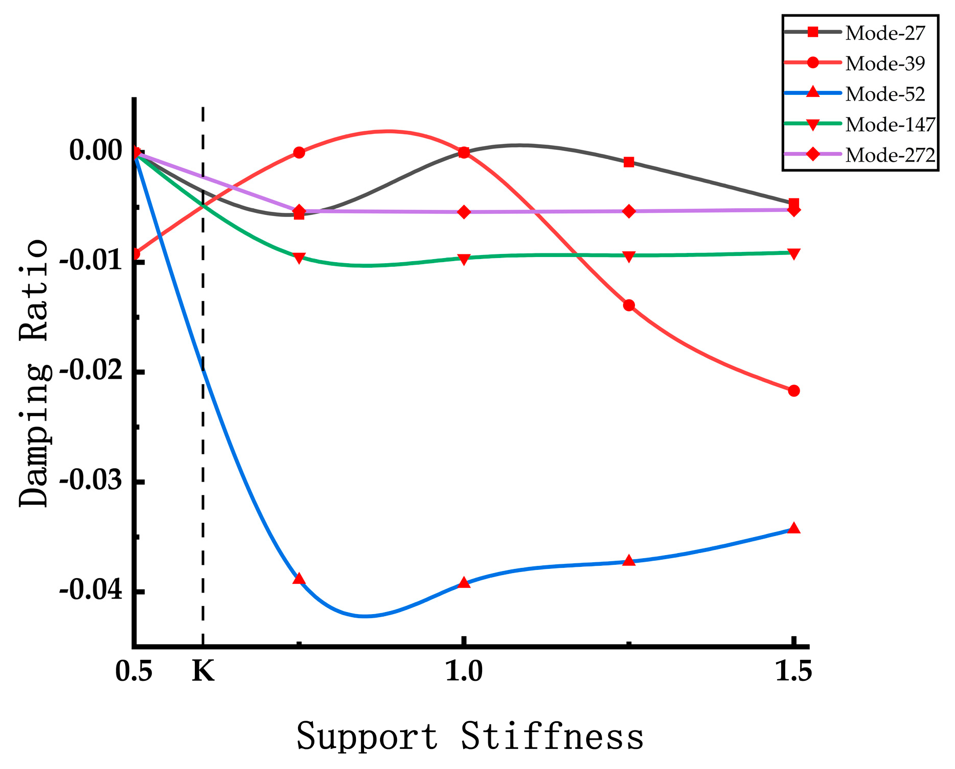
To further examine the variation in the negative damping ratio with changes in rail support stiffness, five unstable modes are extracted for comparative analysis. The resulting sample curve depicting the negative damping ratio in relation to the variation in overall support stiffness is presented in Figure 13.
Among the five modes selected, four modes began to become unstable between and , and then tended to be stable and decreased slightly. The 39th-order mode is in a stable state under , and instability occurs at lower stiffness and higher stiffness. Upon comparing the various curves in Figure 13, it becomes evident that the negative damping ratio of unstable modes responds differently to changes in rail support stiffness. These responses include decreasing, increasing, and maintaining stability, signifying that rail support stiffness exerts varying degrees of influence on different modes.
Given that the frequency characteristics of actual wheel–rail curve squeal noise may be determined by one of these unstable modes, it is essential to minimize the negative damping of the actual self-excited vibration input system. This can be achieved by incorporating as many unstable modes as possible within a low damping ratio range during the optimization of support stiffness. As exemplified by the observation in Figure 11, it is noticeable that the negative damping ratio for each mode remains at a low level. In theory, it is feasible to select an appropriate rail support stiffness to effectively control curve squeal noise.
5. Conclusions
In this study, a comprehensive analysis of wheel–rail curve squeal noise is conducted by establishing a three-dimensional solid finite element model of the wheel–rail system using finite element software ABAQUS 2022. The investigation focuses on the stability analysis of the system under train slip conditions in small radius curved lines. The primary objectives are to delve into the mechanism, location, and influencing factors of wheel–rail curve squeal noise. The methodology employed employs modal coupling theory and the complex eigenvalue analysis method to calculate the complex modes of the wheel–rail system. Subsequently, unstable modes are extracted, and their modal characteristics are thoroughly examined and discussed. Lastly, the impact of wheel–rail stiffness matching on the propensity for curve squeal is explored, and approaches to mitigate curve squeal are proposed from this perspective. This comprehensive research leads to the following specific conclusions:
- In comparison to the resonant modes of the wheel and rail, as well as the unstable modes within the wheel–rail system, it is evident that the frequencies of these unstable modes closely align with the resonant frequencies of the wheel and rail. Furthermore, the mode shapes of these unstable modes bear a striking resemblance to the resonant mode shapes of the wheel and rail. Specifically, the wheel predominantly exhibits axial vibrations along the 0-pitch-circle axial mode, while the rail primarily experiences vertical bending vibrations. Notably, the axial vibration of the wheel interacts with the vertical vibration of the rail, resulting in the occurrence of frictional self-excited vibrations.
- When considering the amplitude of complex mode shapes concerning the occurrence of wheel–rail curve squeal noise, it becomes evident that the noise primarily originates from vibrations occurring at three key positions: the rim, railhead, and rail foot.
- The wheel–rail stiffness exerts a significant influence on curve squeal noise. Analyzing its impact from the perspective of wheel–rail stiffness matching offers valuable insights into controlling curve squeal noise effectively. When the difference in elastic modulus between the rail and wheel is excessively large or small, it tends to increase the likelihood of squeal noise occurrence. The optimal ratio of elastic modulus between the rail and wheel is approximately 1.2, providing a guideline for effective noise control measures.
- The rail support stiffness does have a discernible impact on curve squeal noise. Theoretically, maintaining an appropriate support stiffness level keeps the negative damping ratio of the system’s unstable modes at a minimal level, thereby reducing the energy input into the system during self-excited vibration. Consequently, control of wheel–rail curve squeal noise can be achieved by carefully managing the rail support stiffness.
Author Contributions
Conceptualization, S.H.; data curation, Y.G. and G.Z.; investigation, J.J.; methodology, Y.G., G.Z., M.Y., N.C. and S.H.; supervision, Y.G., M.Y., J.J., N.C. and S.H.; writing—original draft, Y.G. and G.Z.; writing—review and editing, Y.G., G.Z., M.Y., J.J., N.C. and S.H. All authors have read and agreed to the published version of the manuscript.
Funding
This work is supported by the Fundamental Research Funds for the Central Universities (2023ZYGXZR089), Shandong Provincial Natural Fund Project (ZR2020QE248) and Science and Technology Planning Project of Guangdong Province (Foreign Experts Program of Department of Science and Technology of Guangdong Province, China).
Institutional Review Board Statement
Not applicable.
Informed Consent Statement
Not applicable.
Data Availability Statement
Not applicable.
Conflicts of Interest
The authors declare no conflict of interest.
References
- Han, B.; Yang, Z.; Yu, Y.; Qian, L.; Chen, J.; Ran, J.; Sun, Y.; Xi, Z.; Lu, F. Statistical Analysis of Urban Rail Transit Operation in the World in 2020: A Review. Urban Rapid Rail Transit 2021, 34, 5–11. [Google Scholar]
- Hou, X.F.; Mei, J.P.; Zuo, C.; Liu, G.Y. Statistics and Analysis of Urban Rail Transit in 2020. Urban Rapid Rail Transit 2021, 34, 1–9+64. [Google Scholar]
- Da-xin, S.; Liang, G. Wheel/Rail Noise on High Speed Railway and Its Control Measures. China Saf. Sci. J. 2005, 15, 87–90. [Google Scholar]
- Jia-hua, L.; Song-liang, L. Vibration and noise of the urban rail transit. J. Traffic Transp. Eng. 2002, 2, 29–33. [Google Scholar]
- Zhang, B.; Lu, X.; Di, G. Effects of Railwav Noise on Residential Quarter. Environ. Sci. 2003, 24, 157–160. [Google Scholar]
- Kurzweil, L. Wheel/rail noise—Means for control. J. Sound. Vib. 1983, 87, 197–220. [Google Scholar] [CrossRef]
- Eadie, D.T.; Santoro, M. Top-of-rail friction control for curve noise mitigation and corrugation rate reduction. J. Sound. Vib. 2006, 293, 747–757. [Google Scholar] [CrossRef]
- Gao, C.; Kuhlmann-Wilsdorf, D. On stick-slip and the velocity dependence of friction at low speeds. J. Tribol. 1990, 112, 354–360. [Google Scholar] [CrossRef]
- Ibrahim, R.A. Friction-induced vibration, chatter, squeal, and chaos—Part II: Dynamics and modeling. Appl. Mech. Rev. 1994, 47, 227–253. [Google Scholar] [CrossRef]
- Chen, G.; Liu, Q.; Jin, X.; Zhou, Z. Stability analysis of a squealing vibration model with time delay. J. Sound. Vib. 2008, 311, 516–536. [Google Scholar] [CrossRef]
- Gdaniec, P.; Weiß, C.; Hoffmann, N. On chaotic friction induced vibration due to rate dependent friction. Mech. Res. Commun. 2010, 37, 92–95. [Google Scholar] [CrossRef]
- Heckl, M.A.; Abrahams, I.D. Curve squeal of train wheels, part 1: Mathematical model for its generation. J. Sound. Vib. 2000, 229, 669–693. [Google Scholar] [CrossRef]
- Shin, K.; Brennan, M.; Oh, J.-E.; Harris, C. Analysis of disc brake noise using a two-degree-of-freedom model. J. Sound. Vib. 2002, 254, 837–848. [Google Scholar] [CrossRef]
- Paliwal, M.; Mahajan, A.; Don, J.; Chu, T.; Filip, P. Noise and vibration analysis of a disc–brake system using a stick–slip friction model involving coupling stiffness. J. Sound. Vib. 2005, 282, 1273–1284. [Google Scholar] [CrossRef]
- Liu, X.; Meehan, P.A. Investigation of the effect of lateral adhesion and rolling speed on wheel squeal noise. Proc. Inst. Mech. Eng. Part. F J. Rail Rapid Transit 2013, 227, 469–480. [Google Scholar] [CrossRef]
- Liu, X.; Meehan, P.A. Investigation of the effect of relative humidity on lateral force in rolling contact and curve squeal. Wear 2014, 310, 12–19. [Google Scholar] [CrossRef]
- Liu, X.; Meehan, P.A. Wheel squeal noise: A simplified model to simulate the effect of rolling speed and angle of attack. J. Sound. Vib. 2015, 338, 184–198. [Google Scholar] [CrossRef]
- Chen, G.; Zhou, Z.; Kapsa, P.; Vincent, L. Experimental investigation into squeal under reciprocating sliding. Tribol. Int. 2003, 36, 961–971. [Google Scholar] [CrossRef]
- Liu, X.; Meehan, P.A. Investigation of squeal noise under positive friction characteristics condition provided by friction modifiers. J. Sound. Vib. 2016, 371, 393–405. [Google Scholar] [CrossRef]
- Hoffmann, N.; Fischer, M.; Allgaier, R.; Gaul, L. A minimal model for studying properties of the mode-coupling type instability in friction induced oscillations. Mech. Res. Commun. 2002, 29, 197–205. [Google Scholar] [CrossRef]
- Hoffmann, N.; Gaul, L. Effects of damping on mode-coupling instability in friction induced oscillations. ZAMM-J. Appl. Math. Mech./Z. Für Angew. Math. Und Mech. Appl. Math. Mech. 2003, 83, 524–534. [Google Scholar] [CrossRef]
- Han, M.-G.; Park, C.-K.; Chang, S. A study of drum brake squeal using complex eigenvalue analysis. In Proceedings of the 32nd International Congress and Exposition on Noise Control Engineering, Seogwipo, Republic of Korea, 25–28 August 2003; pp. 4578–4585. [Google Scholar]
- Ouyang, H.; Nack, W.; Yuan, Y.; Chen, F. On Automotive Disc Brake Squeal Part II: Simulation and Analysis; SAE Technical Paper: Warrendale, PA, USA, 2003. [Google Scholar]
- Brunel, J.F.; Dufrenoy, P.; Nat, M.; Muoz, J.L.; Demilly, F. Transient models for curve squeal noise. J. Sound. Vib. 2006, 293, 758–765. [Google Scholar] [CrossRef]
- Chen, G.X.; Xiao, J.B.; Liu, Q.Y.; Zhou, Z.R. Complex Eigenvalue Analysis of Railway Curve Squeal. Notes Numer. Fluid. Mech. Multidiscip. Des. 2008, 99, 433–439. [Google Scholar]
- Pieringer, A. A numerical investigation of curve squeal in the case of constant wheel/rail friction. J. Sound. Vib. 2014, 333, 4295–4313. [Google Scholar] [CrossRef]
- Liu, S.; De Silva, U.; Chen, D.; Leslie, A.C.; Meehan, P.A. Investigation of wheel squeal noise under mode coupling using two-disk testrig experiments. Wear 2023, 530, 205035. [Google Scholar] [CrossRef]
- Ding, B.; Squicciarini, G.; Thompson, D. Effect of rail dynamics on curve squeal under constant friction conditions. J. Sound. Vib. 2019, 442, 183–199. [Google Scholar] [CrossRef]
- Lai, V.-V.; Chiello, O.; Brunel, J.-F.; Dufrenoy, P. The critical effect of rail vertical phase response in railway curve squeal generation. Int. J. Mech. Sci. 2020, 167, 105281. [Google Scholar] [CrossRef]
- Zhan, B.; Sun, T.; Shen, Y.; Yu, J.; Tao, Z.; Hu, H. Improvement of brake squeal of a disc brake based on complex eigenvalue analysis. Zhendong Yu Chongji/J. Vib. Shock. 2021, 40, 108–112+135. [Google Scholar]
- Guan, D.; Jiang, D. A Study on Disc Brake Squeal Using Finite Element Methods; SAE Technical Paper: Warrendale, PA, USA, 1998. [Google Scholar]
Figure 1.
Theoretical analysis framework.

Figure 2.
FEA model of the wheel–rail system and its parts: (a) wheel; (b) rail; (c) sleeper; (d) track plate; (e) wheel–rail system.
Figure 2.
FEA model of the wheel–rail system and its parts: (a) wheel; (b) rail; (c) sleeper; (d) track plate; (e) wheel–rail system.
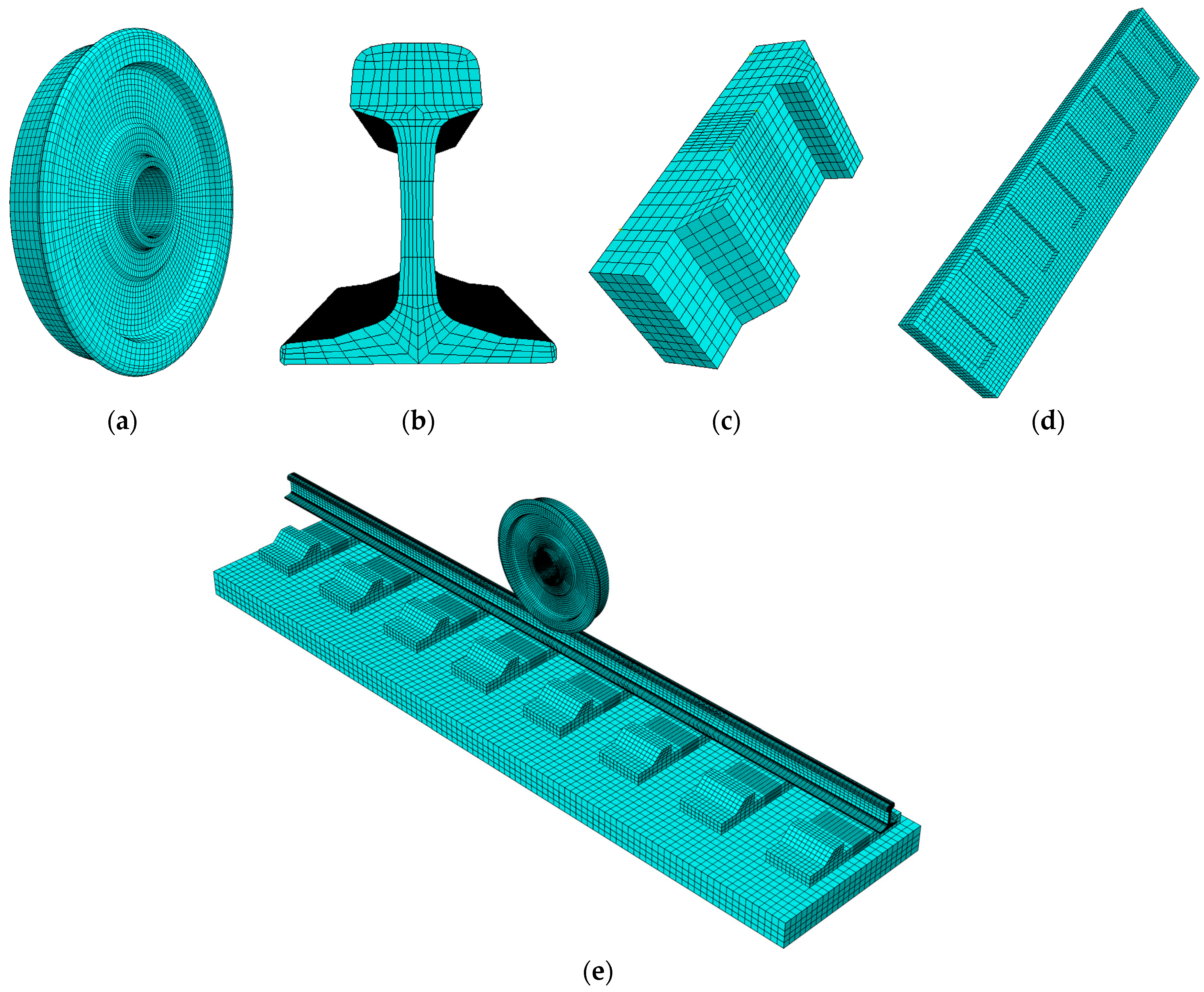
Figure 3.
Transverse frictional force.
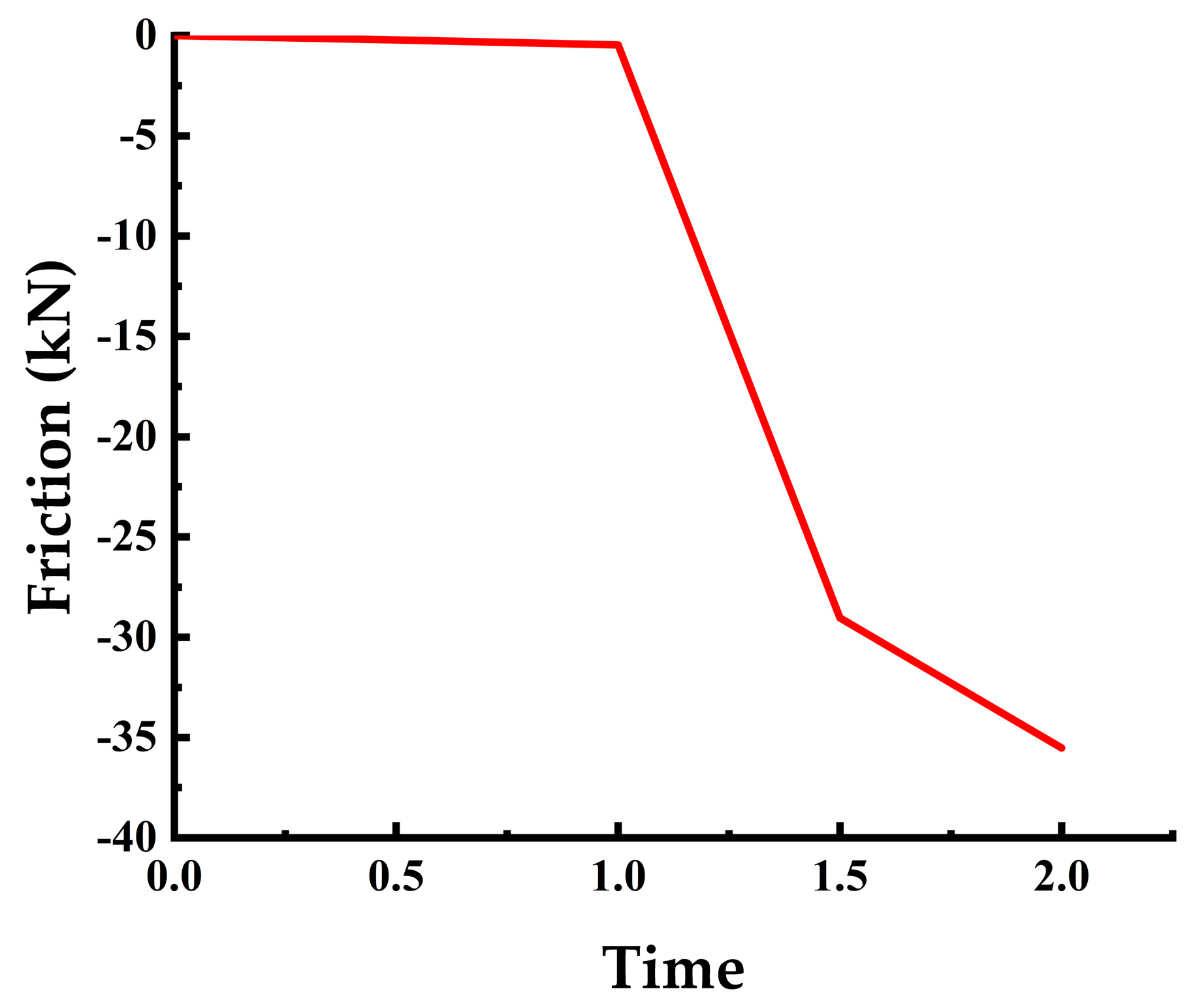
Figure 4.
Partial modal shapes of wheel: (a) (1,0) mode; (b) (2,0) mode; (c) (6,0) mode; (d) (1,1) mode; (e) (2,1) mode; (f) (3,1) mode; (g) 1 pitch diameter; (h) 2 pitch diameters.
Figure 4.
Partial modal shapes of wheel: (a) (1,0) mode; (b) (2,0) mode; (c) (6,0) mode; (d) (1,1) mode; (e) (2,1) mode; (f) (3,1) mode; (g) 1 pitch diameter; (h) 2 pitch diameters.
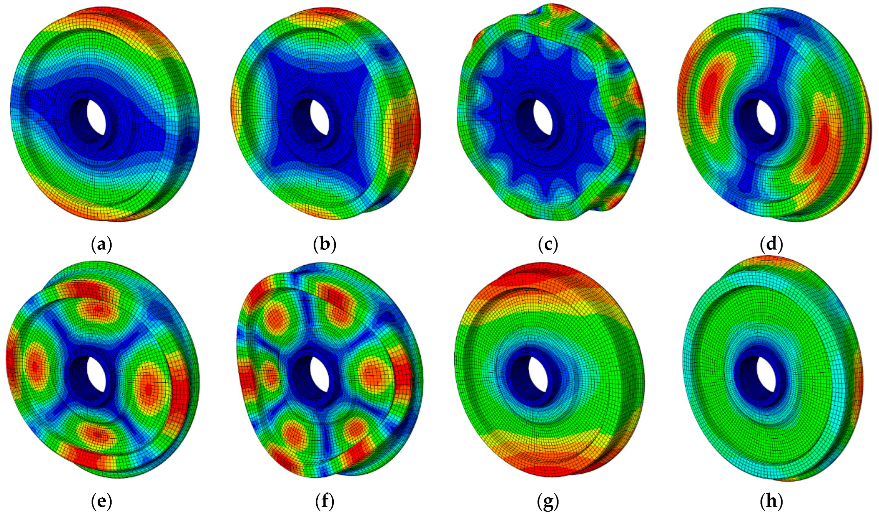
Figure 5.
Displacement responses of wheel: (a) radial displacement response; (b) axial displacement response.
Figure 5.
Displacement responses of wheel: (a) radial displacement response; (b) axial displacement response.
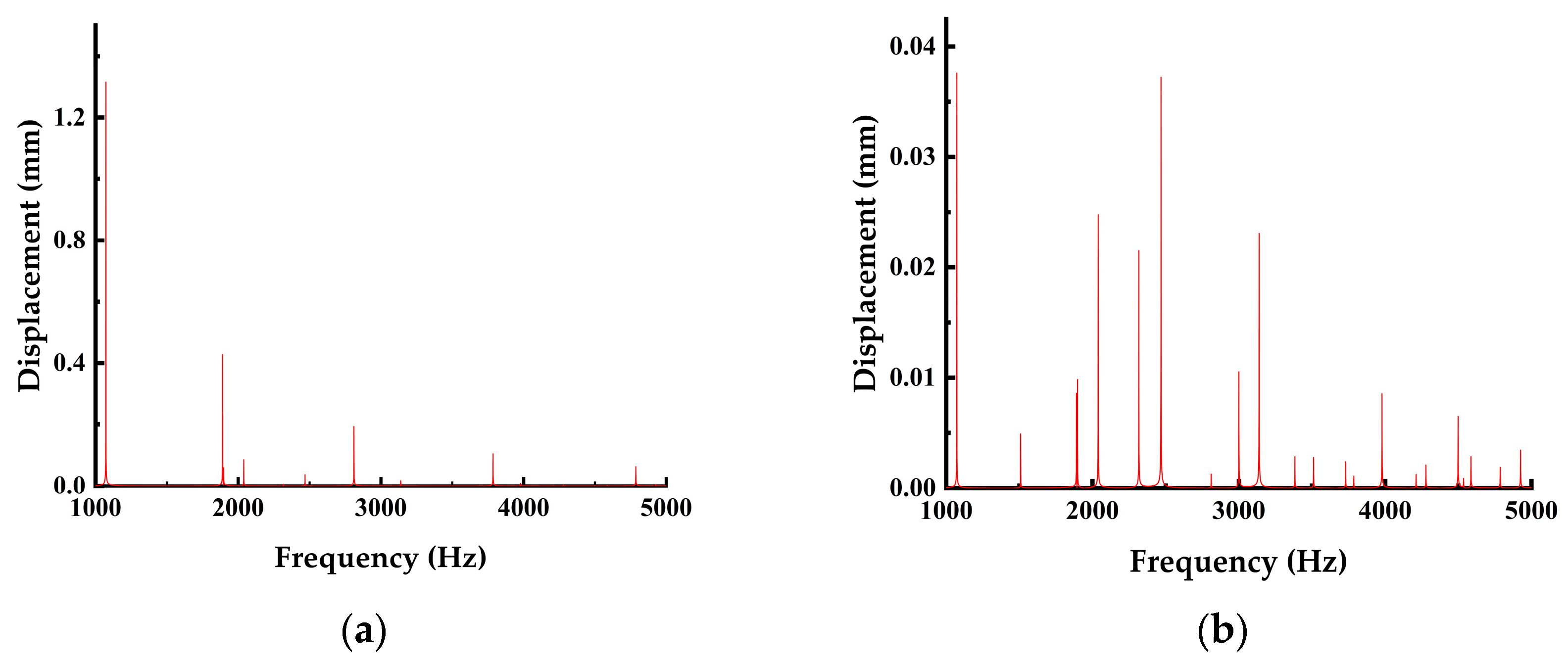
Figure 6.
Summary of mode shapes at wave crest frequency: (a) 1072.60 Hz; (b) 1890.56 Hz; (c) 2038.69 Hz; (d) 2468.33 Hz; (e) 2811.14 Hz; (f) 3785 Hz; (g) 4786.55 Hz.
Figure 6.
Summary of mode shapes at wave crest frequency: (a) 1072.60 Hz; (b) 1890.56 Hz; (c) 2038.69 Hz; (d) 2468.33 Hz; (e) 2811.14 Hz; (f) 3785 Hz; (g) 4786.55 Hz.
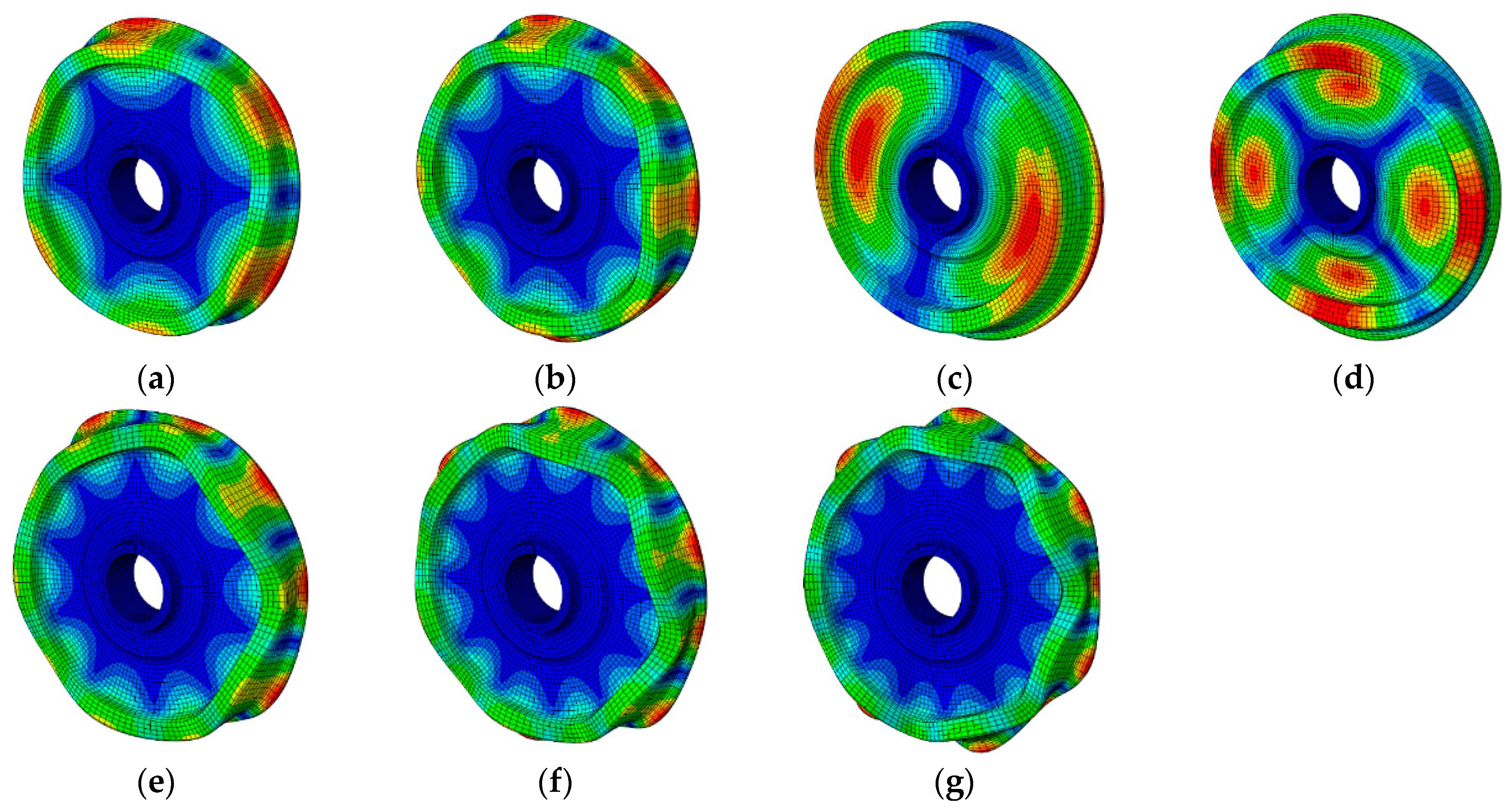
Figure 7.
Displacement response of rail: (a) vertical displacement response; (b) lateral displacement response.
Figure 7.
Displacement response of rail: (a) vertical displacement response; (b) lateral displacement response.

Figure 8.
Partial modal shapes of rail at the wave crest frequency: (a) 1180.7 Hz; (b) 1442.2 Hz; (c) 2469.7 Hz; (d) 3806.4 Hz.
Figure 8.
Partial modal shapes of rail at the wave crest frequency: (a) 1180.7 Hz; (b) 1442.2 Hz; (c) 2469.7 Hz; (d) 3806.4 Hz.
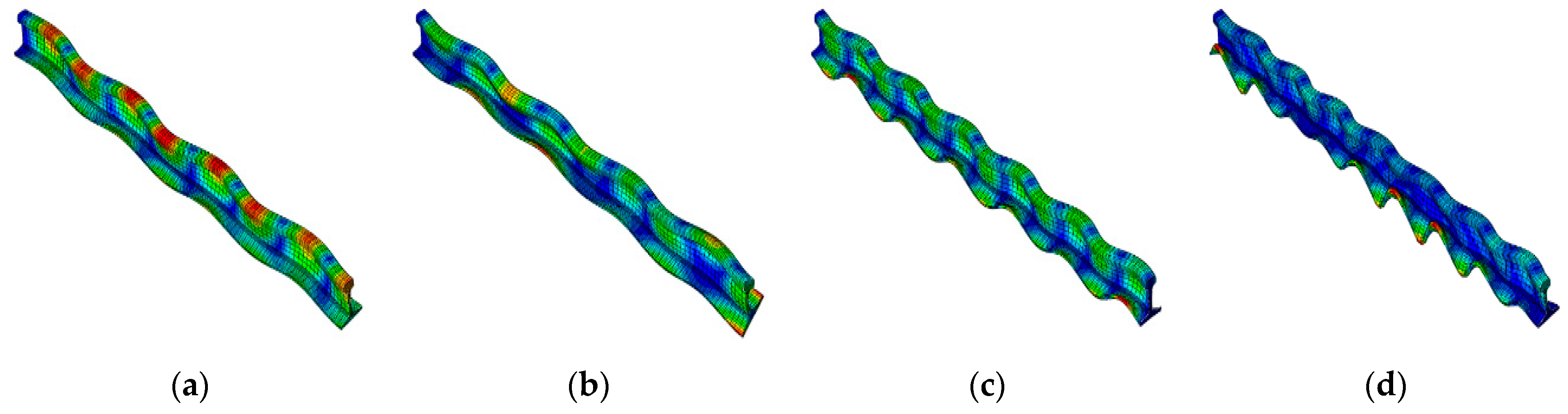
Figure 9.
Complex mode analysis results of the wheel–rail system.
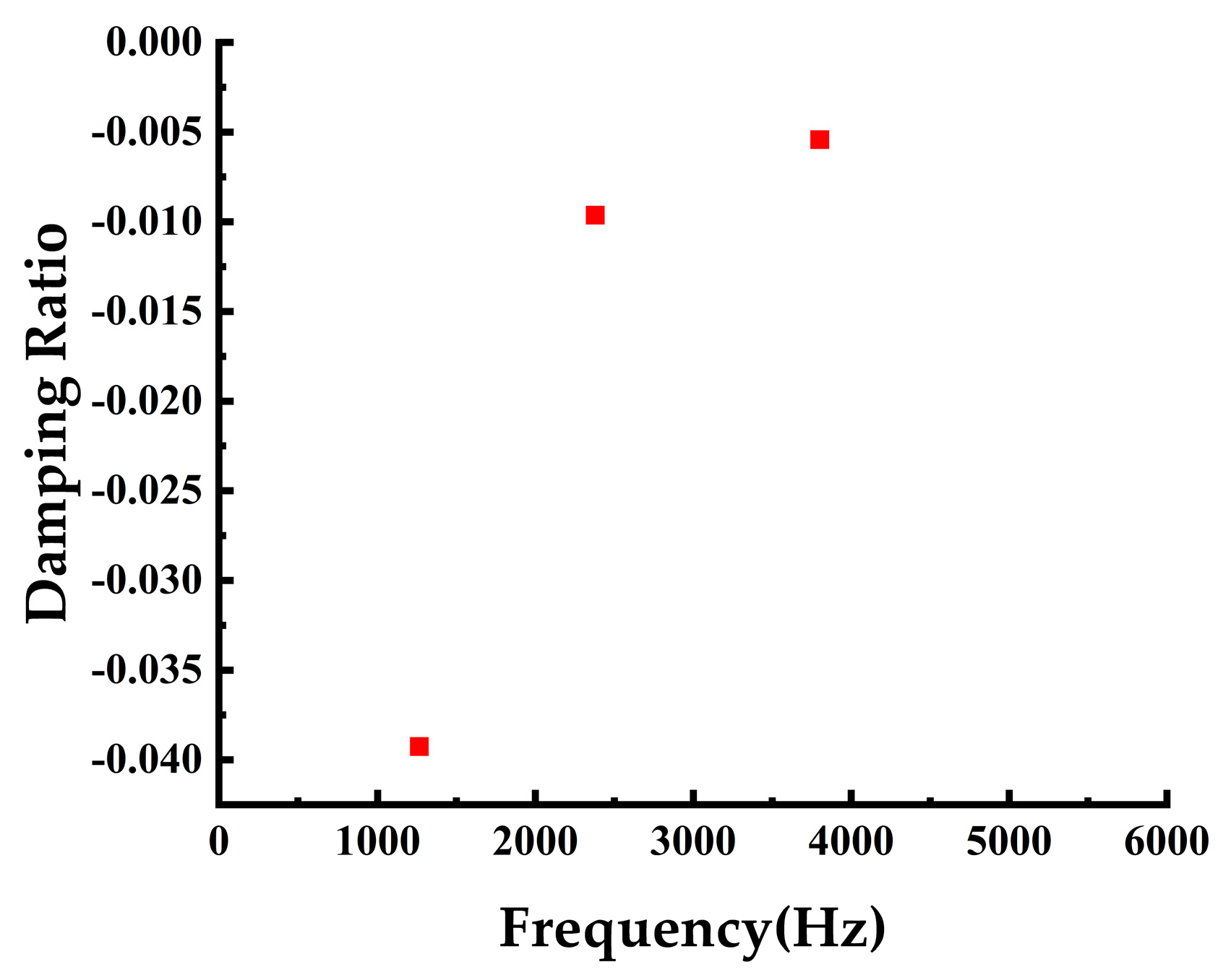
Figure 10.
Amplitudes of the modal shapes of the unstable modes of the wheel–rail system: (a) 52nd-order mode; (b) 147th-order mode; (c) 272nd-order mode.
Figure 10.
Amplitudes of the modal shapes of the unstable modes of the wheel–rail system: (a) 52nd-order mode; (b) 147th-order mode; (c) 272nd-order mode.
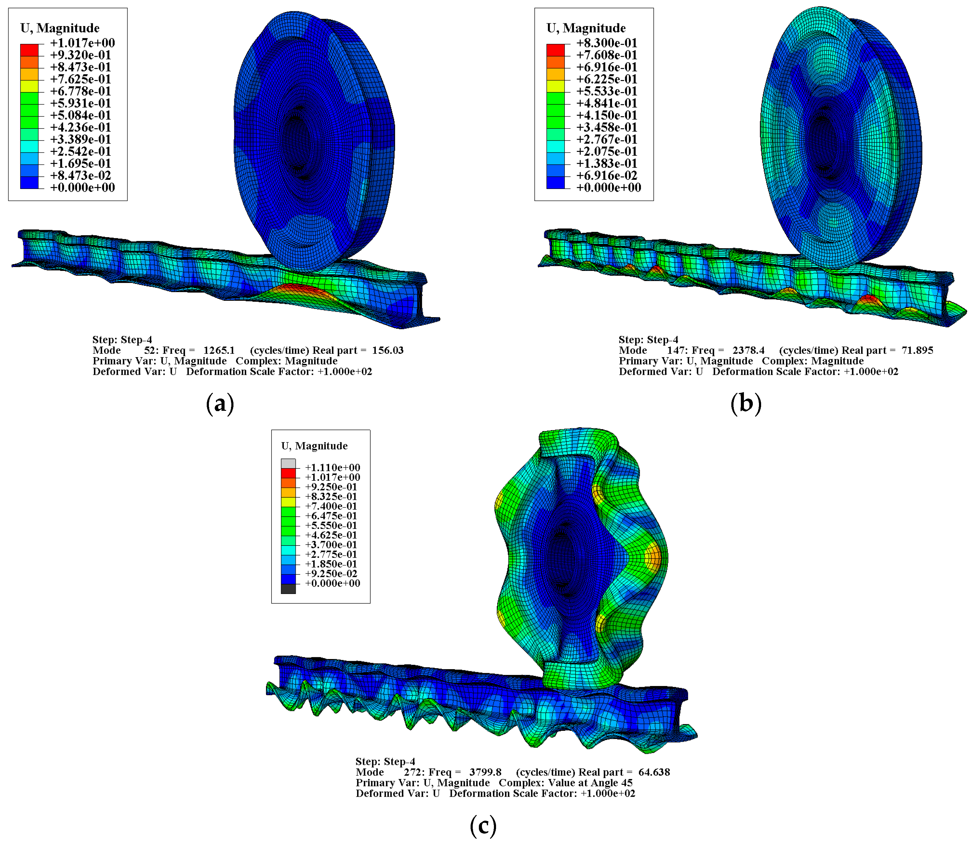
Figure 11.
Frequency domain distribution of negative damping ratio under different elastic modulus of the rail: (a) 1.5 × 10⁵ MPa; (b) 1.8 × 10⁵ Mpa; (c) 2.1 × 10⁵ Mpa; (d) 2.4 × 10⁵ Mpa.
Figure 11.
Frequency domain distribution of negative damping ratio under different elastic modulus of the rail: (a) 1.5 × 10⁵ MPa; (b) 1.8 × 10⁵ Mpa; (c) 2.1 × 10⁵ Mpa; (d) 2.4 × 10⁵ Mpa.
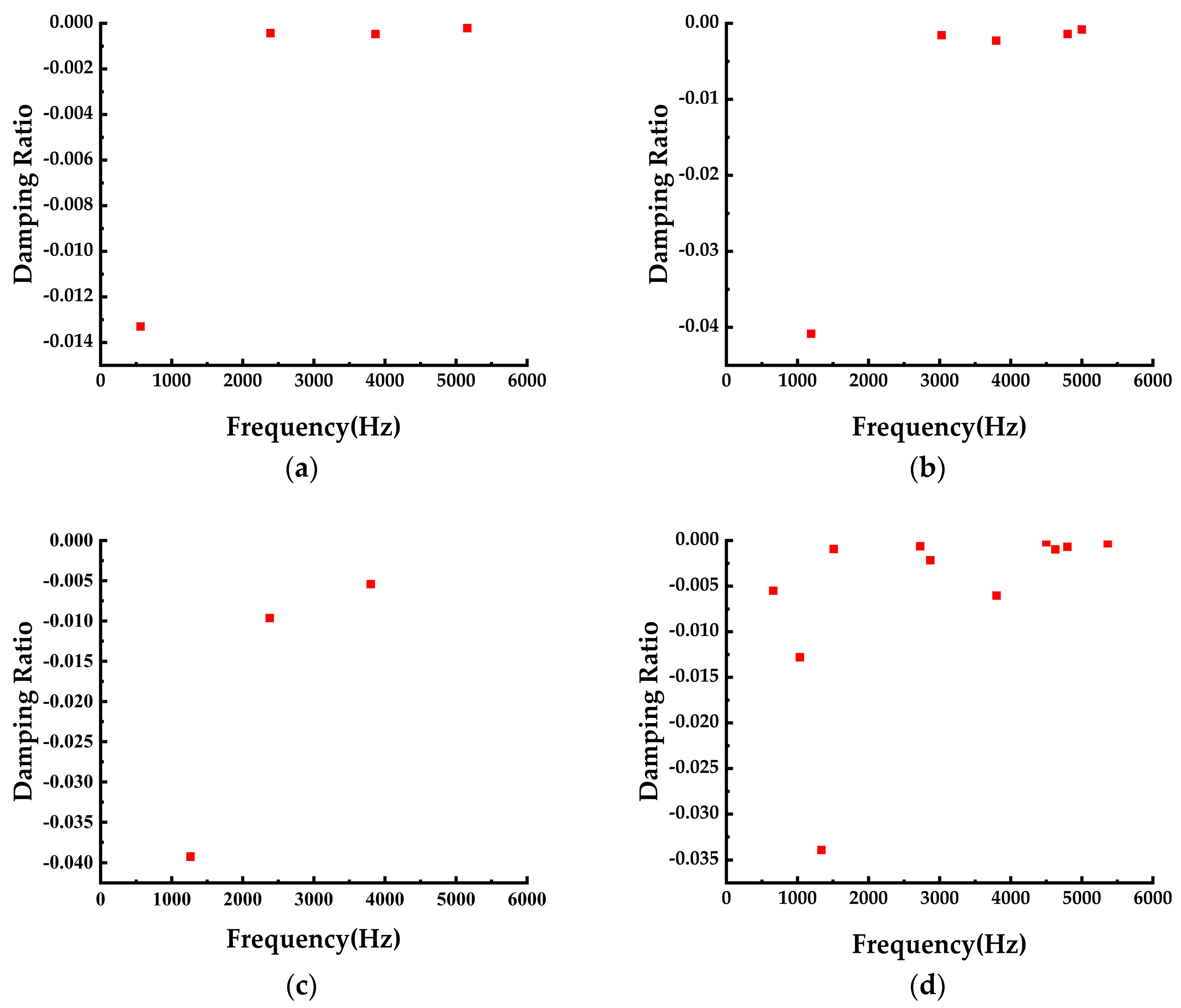
Figure 12.
Frequency domain distribution of negative damping ratio under different support stiffness: (a) 0.5 ; (b) 0.75 ; (c) 1.25 ; (d) 1.5 .
Figure 12.
Frequency domain distribution of negative damping ratio under different support stiffness: (a) 0.5 ; (b) 0.75 ; (c) 1.25 ; (d) 1.5 .
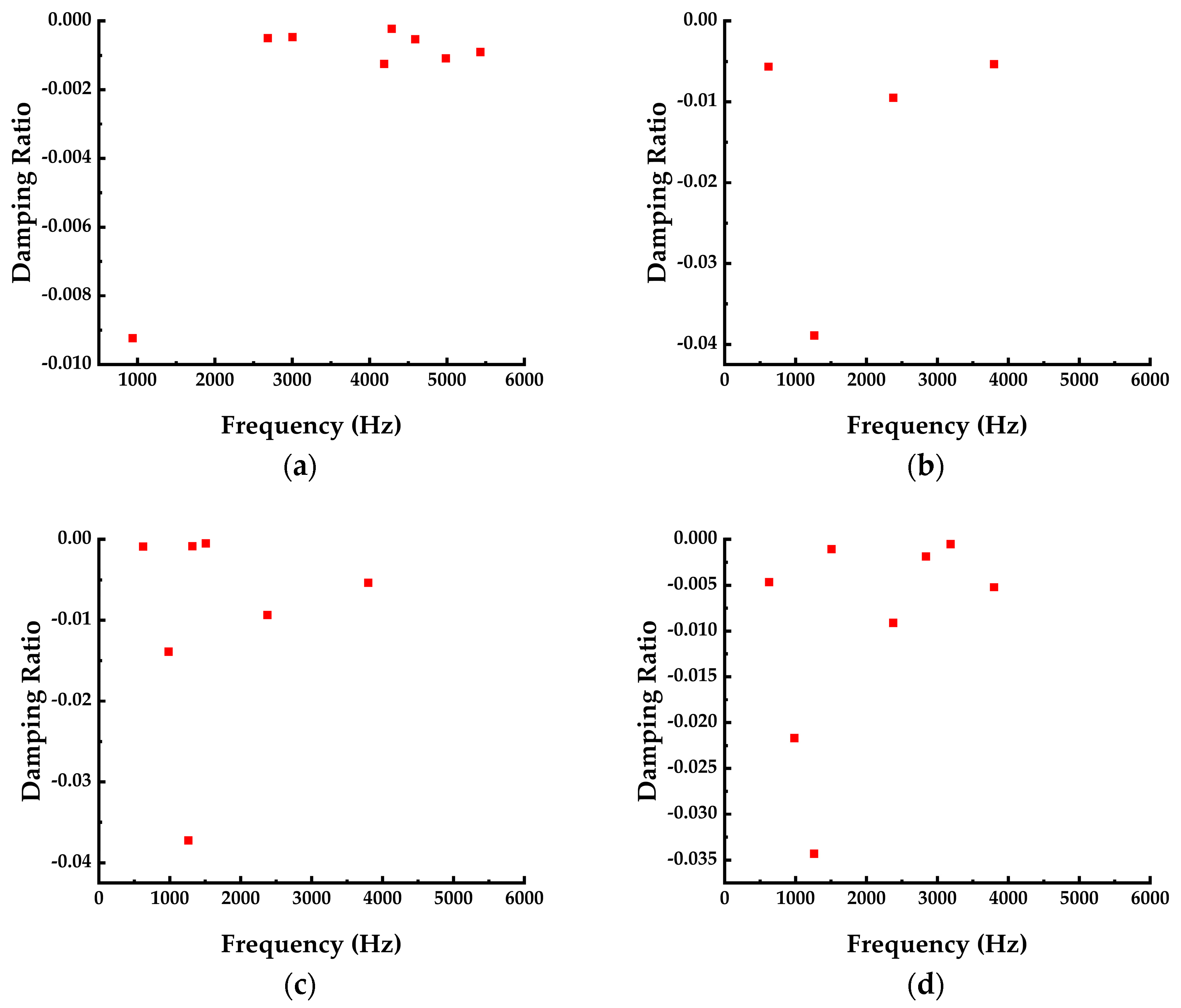
Figure 13.
Negative damping ratio variation curve with the support stiffness of rail.

Table 1.
Material properties of the wheel–rail system.
| Structure Name | Elastic Modulus (MPa) | Density (kg/m3) | Poisson Ratio |
|---|---|---|---|
| Wheel | 1.8 × 10⁵ | 7800 | 0.28 |
| Rail | 2.1 × 10⁵ | 7800 | 0.3 |
| Sleeper | 3.45 × 10⁴ | 2500 | 0.2 |
| Track plate | 3.45 × 10⁴ | 2500 | 0.2 |
Table 2.
Unstable modal shape analysis of the wheel–rail system.
| Modal Order | Modal Frequency | Main Vibration Position | Max. Amplitude |
|---|---|---|---|
| 52 | 1265.1 Hz | Rail foot | 1.02 |
| 147 | 2378.4 Hz | Rail foot | 0.83 |
| 272 | 3799.8 Hz | Wheel Rims | 1.11 |
Table 3.
TOI values under different elastic modulus conditions.
| Elastic Modulus (MPa) | Number of Unstable Modes | TOI |
|---|---|---|
| 1.5 × 10⁵ | 4 | 14.398 |
| 1.8 × 10⁵ | 5 | 54.293 |
| 2.1 × 10⁵ | 3 | 46.870 |
| 2.4 × 10⁵ | 11 | 64.067 |
Table 4.
TOI values under different support stiffness conditions.
| ) | Number of Unstable Modes | TOI |
|---|---|---|
| 0.5 | 8 | 14.198 |
| 0.75 | 4 | 59.383 |
| 1 | 3 | 54.293 |
| 1.25 | 7 | 68.101 |
| 1.5 | 11 | 78.444 |
Disclaimer/Publisher’s Note: The statements, opinions and data contained in all publications are solely those of the individual author(s) and contributor(s) and not of MDPI and/or the editor(s). MDPI and/or the editor(s) disclaim responsibility for any injury to people or property resulting from any ideas, methods, instructions or products referred to in the content. |
© 2023 by the authors. Licensee MDPI, Basel, Switzerland. This article is an open access article distributed under the terms and conditions of the Creative Commons Attribution (CC BY) license (https://creativecommons.org/licenses/by/4.0/).
Share and Cite
MDPI and ACS Style
Gao, Y.; Zhang, G.; Yuan, M.; Ji, J.; Cui, N.; Huang, S. The Numerical Study for the Effect of Stiffness Matching on Wheel–Rail Curve Squeal Noise. Appl. Sci. 2023, 13, 11615. https://doi.org/10.3390/app132111615
AMA Style
Gao Y, Zhang G, Yuan M, Ji J, Cui N, Huang S. The Numerical Study for the Effect of Stiffness Matching on Wheel–Rail Curve Squeal Noise. Applied Sciences. 2023; 13(21):11615. https://doi.org/10.3390/app132111615
Chicago/Turabian StyleGao, Yanxin, Gongde Zhang, Miaomiao Yuan, Jianyi Ji, Nannan Cui, and Shiping Huang. 2023. "The Numerical Study for the Effect of Stiffness Matching on Wheel–Rail Curve Squeal Noise" Applied Sciences 13, no. 21: 11615. https://doi.org/10.3390/app132111615
Note that from the first issue of 2016, this journal uses article numbers instead of page numbers. See further details here.