
Centrifuge Modelling of the Impact of Excavation with Partition Piles on Adjacent Existing Tunnel
by
Yiming Du
1,2,
Bingyi Wang
1,2,*,
Yu Diao
1,2,
Haotian Zhao
1,2,
Xiangyu Zhao
1,2 and
Yiming Su
1,2 1
School of Civil Engineering, Tianjin University, Tianjin 300072, China
2
Key Laboratory of Coast Civil Structures and Safety of Ministry of Education, Tianjin University, Tianjin 300072, China
*
Author to whom correspondence should be addressed.
Appl. Sci. 2023, 13(24), 13064; https://doi.org/10.3390/app132413064
Submission received: 13 November 2023
/
Revised: 4 December 2023
/
Accepted: 6 December 2023
/
Published: 7 December 2023
(This article belongs to the Special Issue Environmental Impact and Control of Geotechnical Engineering Construction)
Abstract
:Recently, due to more excavation projects near existing tunnels, the research on tunnel deformation control has become very important and urgent. However, the systematic study of the control effectiveness of partition piles, one of the commonly used methods for controlling tunnel deformation, was not mature yet. In response to this situation, a series of centrifuge modelling studies were performed to explore how nearby existing tunnels respond to excavations with partition piles in a dry sand foundation. The tests provided insights into the variations of the horizontal displacement of retaining walls, surface settlement, the horizontal and vertical displacements of the tunnel, and the circular induced strain of the tunnel. The test results showed that the horizontal displacement of retaining walls exhibited a cantilever-type displacement pattern. The most significant surface settlement occurred near the retaining wall and decreased as the distance from the retaining wall increased. The overall deformation of the tunnel roughly showed an ellipsoidal deformation pattern in the horizontal direction. The maximum horizontal displacement was observed at the right shoulder of the tunnel, while the maximum vertical displacement occurred at the right arch of the tunnel. Increasing the length of the partition piles led to a deterioration in their deformation control effectiveness. The top burial depth of the pile could further improve the control effectiveness of the partition piles. However, when the top burial depth of the pile was excessive and exceeded its critical value, the improvement effect of the burial depth on the partition piles diminished.
1. Introduction
With the growth of urban populations and the limitations of land resources, the utilization of underground spaces is increasing. Urban underground rail transit, as an effective means to alleviate urban traffic pressure through the utilization of underground space, continues to expand and be constructed worldwide. Alongside this, the excavation work near existing metro tunnels has been a typical occurrence [1,2,3,4,5,6,7,8]. Excavation can lead to issues such as groundwater level lowering, soil deformation, and vibrations induced by earthquakes, which in turn can result in additional internal forces and deformations in existing tunnels, posing potential impacts on tunnel safety. Therefore, research on the effects of excavation on nearby tunnels has gained significant importance and urgency.
In recent years, numerous scholars have undertaken a series of studies on this matter [9,10,11,12,13,14,15,16,17,18,19,20,21]. Doležalová [9] examined how deep excavation affects an underground tunnel network in a specific office building using a 2D finite element model. The model calculations showed a maximum heave of 22 mm in the basement. The maximum tunnel heave and diameter change in the existing tunnel network reached 14 mm and 4.5 mm, and the finite element calculation results matched well with the measured results. Ng et al. [10], on the other hand, conducted three-dimensional centrifuge modelling, and it was found that the excavation has an approximate influence range of 1.2 times the length of the tunnel on its longitudinal vertical displacement. The maximum upward movement of the under tunnel and the greatest settlement of the neighboring tunnel were approximately 0.07% and 0.014% of the excavation depth, respectively. Xu et al. [11] conducted a battery of centrifuge modelling experiments and determined that the influence range of tunnel heave extended to approximately 2.5 times the excavation width from the excavation boundary. Chen et al. [12] conducted centrifuge modelling and found that the total settlement of the tunnel reached 1.6 times the settlement during excavation after 815 days of completion of excavation. Sharma et al. [13] employed field monitoring and numerical simulation analysis to investigate the effects of a substantial excavation on adjacent subway tunnels. The results showed that tunnels with high-stiffness linings might have smaller deformations but might have to withstand larger moments.
Simultaneously, ensuring the long-term and sustainable operation of existing subway tunnels became a significant concern in urban underground engineering construction. There were various measures to control the deformation of existing subway tunnels caused by underground construction, such as phased excavation, soil grouting reinforcement, and pile reinforcement [22,23,24,25,26,27,28,29]. A noticeable gap often existed between the existing tunnels and the excavation retaining structures. In engineering practice, partition piles or walls were frequently installed in this area to impede the transmission of deformation from the excavation to the surrounding soil, thereby minimizing the deformation of the existing tunnels.
However, in recent years, research on partition piles has yielded varying conclusions regarding their effectiveness in controlling tunnel deformation [30,31,32,33,34,35,36,37,38,39,40]. Ying et al. [32] found that the presence of a partition wall can significantly reduce the maximum surface settlement outside the excavation and horizontal displacement of the retaining wall, leading to a noticeable reduction in damage to surrounding structures caused by excavation. Nonetheless, the partition wall’s impact on the displacement field of deep soil demonstrated substantial variation with depth. Zheng et al. [35] employed numerical analysis to investigate the influence of partition piles on the displacement field of the soil surrounding the excavation. The numerical analysis results indicated that partition piles had opposite effects on soil displacement in different regions, as depicted in Figure 1. Thus, the effectiveness of partition piles in controlling the displacement of deep tunnels remained a subject of debate. Chen et al. [37] conducted three-dimensional centrifuge modelling with protective partition walls and found that the installation of the partition wall, to some extent, reduced tunnel heave, but the effect was not very significant. Zheng et al. [38] utilized the numerical simulation method to conduct an extensive parameter study, investigating the action mechanism of partition piles in a substantial and deep excavation project near an existing tunnel in Tianjin. The study findings revealed that under substantial traction effects, partition piles might even significantly increase the horizontal displacement of the soil within a specific depth range, consequently impacting the tunnel within that range. Based on the above-mentioned literature, it was evident that within a certain depth range below the surface, the horizontal displacement of the soil increased when there were partition piles. The presence of partition piles induced displacement in the surrounding soil within this range towards the excavation, and this effect was also known as the traction effect of partition piles. If the existing tunnel happened to be within this range, the horizontal displacement of the tunnel might increase due to the traction effect of the partition piles, which was detrimental to controlling tunnel deformation. Therefore, selecting reasonable design parameters for partition piles was crucial. Increasing their protective effect while reducing the traction effect had a positive significance in achieving optimal deformation control for existing tunnels outside the excavation.
The above studies indicated that the mechanism of partition piles in controlling tunnel deformation was not yet clear, and there was a lack of systematic research on their control effects on soil and tunnels. Furthermore, there were relatively few centrifuge models specifically dedicated to investigating the effects of excavation on nearby existing tunnels and even fewer centrifuge models dedicated to studying the protective effects of partition piles. Therefore, it was necessary to further conduct relevant centrifuge modelling. In this paper, through two-dimensional centrifuge modelling, the study examined the impact of excavation on adjacent tunnels and investigated the controlling effects of partition piles on tunnel deformation in a dry sand foundation. The study obtained the deformation characteristics of tunnels under the influence of excavation and analyzed the patterns of surface settlement, horizontal displacement of retaining walls, and the circular induced strain of the tunnel. By varying the pile length and top burial depth of the pile as variables, the test revealed the patterns of control effects as these parameters changed and unveiled the mechanism of partitioning piles to control tunnel deformation.
2. Design of the Centrifuge Modelling
2.1. Description of the Test
This centrifuge modelling test was conducted in the Geotechnical Engineering Laboratory at Tianjin University, as shown in Figure 2. The model box had internal dimensions of 500 mm × 200 mm × 500 mm.
The primary objective of these experiments was to scrutinize how the parameters of partition piles influence the response of a tunnel during excavation under two-dimensional conditions. Referencing Figure 3, the cross-section was depicted. The tests were carried out with a substantial centrifugal acceleration of 50× g. Due to the limitations of model box size, the excavation depth (H) was 8 m. The excavation width, diameter of the tunnel, and the depth of tunnel crown burial (S) were all designated as 0.5 H, corresponding to 4 m. The distances between the tunnel, retaining wall, and the partition pile were specified as 2 m and 4 m, respectively. The partition pile parameters considered in the test included the top burial depth of the pile (h) and the length of the pile (L). The specific parameter design can be found in Table 1. Moreover, the similarity relationships for the parameters used in the tests are presented in Table 2.
2.2. Model Preparation
2.2.1. Preparation of Soil
The Japanese Toyoura sand was used in this experiment to prepare a dry sand foundation. The method of preparation was the artificial sand raining method, with a drop height of 500 mm, and the sand density was approximately 1.448 g/cm3.
2.2.2. Arrangement of Structural Components
In the model, all structural members of the test were embedded in the soil layer during the preparation of the foundation and were organized along the width bearing of the model box to more fully simulate the two-dimensional state. To ensure the precision of the verticality of the retaining walls and partition walls, the corresponding wall support structure was used during the foundation preparation process. After the walls were fixed, the preparation of the sand soil foundation was carried out in sections. To minimize friction, EVA sponge tape was attached, and Vaseline was applied along the edges of the structure on both sides. For the materials used in the experiment, the structural components were made of innovative magnesium–aluminum alloy material. The material density was 1.78 g/cm3. And its elastic modulus was approximately 40 GPa, which was very close to the elastic modulus of actual concrete materials [41]. Therefore, the dimensions of the structural components in the model could be determined based on the geometric similarity ratio. During the trial, a partition wall was utilized to mimic the piles, and the methodology for assessing wall thickness was derived from considerations of equivalent bending stiffness. Furthermore, the experimental setup incorporated substantial modifications to the partition wall configurations, introducing a distinctive dimension to the overall procedure. The partition piles had a diameter of 8 mm (prototype: 400 mm), and their spacing was 12 mm (prototype: 600 mm). By calculating the equivalent bending stiffness, the thickness of the partition wall was 6 mm (prototype: 300 mm). Furthermore, the specific geometric parameters of the partition wall, retaining wall, and tunnel structure are shown in Table 3.
2.2.3. Heavy Liquid Discharge System
The discharge system for heavy liquids implemented in the conducted experiment was purposefully devised to simulate the excavation process. For the heavy liquid, zinc chloride (ZnCl2) was meticulously prepared, possessing an equivalent density to that of the sand used in the experiment. The system consisted of three main parts: the heavy liquid bag, the discharge pathway, and the collection box. The discharge pathway included the discharge pipe, electromagnetic valve, and the associated power supply. The heavy liquid bag was made by stacking silicone membranes that were 0.3 mm thick and had holes on the side for liquid discharge. The discharge conduit utilized in the experiment was crafted from FEP plastic tubing, featuring an internal diameter of 4 mm and an external diameter of 6 mm. The electromagnetic valve was a small DC24V, normally closed type, and was fixed on top of the collection box, connected to the power supply through slip rings. Considering the dimensions of the centrifuge and the model box, the collection box was made of PP material with internal dimensions of 80 mm × 400 mm × 100 mm. To ensure complete discharge of the heavy liquid, a rubber bend pipe was used. One extremity of the conduit was linked to a hollow screw, while the opposite end was affixed to the base of the bag. This setup utilized the siphon effect to completely discharge the heavy liquid. The overall sequence for heavy liquid discharge was as follows: heavy liquid bag → discharge pipe → electromagnetic valve → collection box. The specific arrangement is shown in Figure 4.
2.2.4. Sensor Arrangement
The primary metrics in this experiment encompassed the lateral shift of the retaining structure, ground-level settlement, and the displacement of the tunnel. Digital Image Correlation (DIC) technology was employed for gauging both the lateral and vertical shifts of the tunnel, as well as the horizontal movement of the retaining wall. There were a total of eight displacement measurement points on the tunnel surface, with specific point locations shown in Figure 2. The depth of the retaining wall displacement measurement points varied at 0, 80, 160, 240, and 320 mm. After calibration, the error of displacement measurements using DIC technology could reach within 2%, meeting the experimental requirements. Therefore, a complete DIC displacement observation system had been designed and implemented, with 13 cameras using the SARGO camera, as shown in Figure 5.
Throughout the experiment, strain gauges were strategically positioned to assess the strain within the tunnel. Specifically, monitoring sections were set up at two-quarter sections of the tunnel along its longitudinal axis. At each section, starting from the tunnel’s crown, a set of full-bridge strain gauges was placed every 90 degrees, totaling eight sets. These gauges were applied to gauge the circular induced strain in the monitored segment of the tunnel, as depicted in Figure 6.
Additionally, surface settlement was measured using a laser displacement sensor. Five settlement measurement points were placed behind the retaining wall at the longitudinal mid-section of the tunnel. The measurement points were located at distances of 0.1 H, 0.5 H, 1.0 H, 1.5 H, and 2.0 H from the retaining wall, where H represented the depth of the excavation. The corresponding model (prototype) dimensions were 16 mm (0.8 m), 80 mm (4 m), 160 mm (8 m), 240 mm (12 m), and 320 mm (16 m), as depicted in Figure 7.
2.3. Testing Procedure
The experiment unfolded through the following sequential steps:
- (1)
- Begin by preparing the foundation soil, arranging the structural components, and installing the sensors, making sure to create the necessary space for the excavation.
- (2)
- Place the heavy liquid bag in the excavation and ensure that the discharge outlet is properly sealed. Then, pour the heavy liquid into the bag.
- (3)
- Commence the centrifuge, gradually ramping up to 50× g. Once the data from diverse sensors stabilizes, activate the electromagnetic valve to commence the discharge of the heavy liquid.
- (4)
- After the completion of excavation and upon the stabilization of sensor data, record the data and halt the centrifuge.
3. Results and Discussion
3.1. Horizontal Displacement of Retaining Wall
Tests 1 to 6 were divided into two groups, namely the comparison group of pile length and the comparison group of top burial depth of the pile. Due to the absence of bracing, the retaining wall showcased a cantilever-type horizontal displacement. In the control group test, the horizontal displacement at the top of the wall measured roughly 1.04 times the depth of excavation, illustrated in Figure 8a. Through the comparison within the pile length group, it could be observed that the presence of partition piles, to some extent, reduced wall displacement, with a maximum reduction of the horizontal displacement of the wall top of 10.6%. Nevertheless, as the length of the partition piles continued to increase, the reduction effect deteriorated. As shown in Figure 8b, through the comparison within the top burial depth of the pile group, it was evident that a certain top burial depth of the pile could improve the control effect of partition piles. However, if it was too large, exceeding its critical value, the improvement effect of the top burial depth of the pile would deteriorate.
3.2. Ground Surface Settlement behind Retaining Wall
Figure 9 illustrates the variation pattern of ground surface settlement behind the retaining wall with the distance from the retaining wall, where ‘S’ represents surface settlement. As depicted in Figure 9, the ground settlement behind the wall reached its peak closest to the retaining wall and gradually diminished with increasing distance from the retaining structure. In the control group, the maximum ground settlement reached 1.1% of the depth of the excavation. Due to the influence of the lead wires from the strain gauges on the tunnel surface, the settlement value at the farthest end position had, to some extent, increased. Overall, the addition of partition piles effectively controlled the maximum ground settlement, reducing it by up to 40.1%. Further observation of Figure 9a,b revealed that the displacement pattern of the ground and the retaining wall was basically consistent. An increase in pile length led to a deterioration in the control effect. Proper top burial depth of the pile did indeed improve the control effect of partition piles, but excessive top burial depth of the pile beyond its critical value resulted in a deterioration of the improvement effect.
3.3. Displacement of Tunnel
The primary emphasis in this centrifuge modelling was on the displacement of the tunnel. As illustrated in Figure 10 and Figure 11, the overall deformation of the tunnel took on an approximately ellipsoidal form in the horizontal direction. The maximum horizontal displacement occurred at the tunnel’s right shoulder, while the maximum vertical displacement was observed at the right arch. In the control group, the maximum horizontal and vertical displacements constituted around 0.3% and 0.17% of the excavation depth, respectively. Chen et al. [37] obtained a maximum tunnel heave of approximately 0.024% of the excavation depth through centrifuge modelling, while Ng et al. [10] measured the maximum tunnel settlement of 0.014% of the excavation depth in their experiments. Due to limitations in the size of the model box, the tunnel depth in this experiment was relatively shallow and closer to the excavation. Therefore, the final tunnel displacement was somewhat larger compared to the values obtained in the previous literature. Through the comparison within the pile length group, it could be seen that the short partition piles in test 2 had the best control effect on tunnel displacement, with a reduction of 36.7% in the maximum horizontal displacement and 31.8% in the maximum vertical displacement. However, as the pile length increased, the control effect of the partition piles deteriorated, and it even increased the tunnel’s displacement. This was because the increase in the pile length led to an increase in its traction effect, resulting in a weakening of the control effect and even a negative effect.
Through a comparison analysis of the group of top burial depth of pile, it could be observed that, compared to test 4, the top burial depth of pile in tests 5 and 6 had improved the effect of the partition piles. In test 5, the improvement of the top burial depth of the pile in maximum horizontal displacement and vertical displacement reached 46.6% and 23.3%, respectively. However, when compared to the control group, the improvement effect was still insufficient, and the partition piles continued to increase tunnel displacement. Furthermore, when the top burial depth of the pile was too deep and exceeded its critical value, the improvement effect on the partition piles deteriorated. Through analysis, it could be concluded that there was a certain dividing point along the length of the partition pile concerning its displacement control effect on the adjacent tunnel. Below this dividing point, the portion of the pile exhibited a barrier effect on the tunnel displacement caused by excavation. Conversely, above the dividing point, the pile exhibited a traction effect on the tunnel. Therefore, moderately incorporating the top burial depth of the pile weakened the traction effect, thereby improving the displacement control effect of the partition pile. However, when the top burial depth of the pile increased to below the dividing point, the barrier effect of the lower part of the partition pile also decreased, and the improvement effect of it on the partition piles deteriorated.
3.4. Convergence Deformation of Tunnel
Figure 12 illustrates the convergence deformations of the tunnel along the horizontal and vertical directions under different experimental conditions, where positive and negative values in the figure denoted tensile deformation and compressive deformation, respectively. From the figure, it could be observed that the unloading effect of the excavation resulted in horizontal elongation and vertical compression of the tunnel. This deformation pattern was highly consistent with the overall horizontal ellipsoidal deformation mode of the tunnel. The influence of partition piles on convergence deformation was generally consistent in both horizontal and vertical directions, with the addition of partition piles leading to an increase in tunnel convergence deformation. Moreover, as the length of the piles increased, the convergence deformation also increased continuously, indicating a negative correlation between pile length and tunnel convergence deformation. The top burial depth of the pile had a certain improvement effect on the control of partition piles in convergence deformation, but the improvement effect was limited.
3.5. Induced Strain in Circular Direction of Existing Tunnel
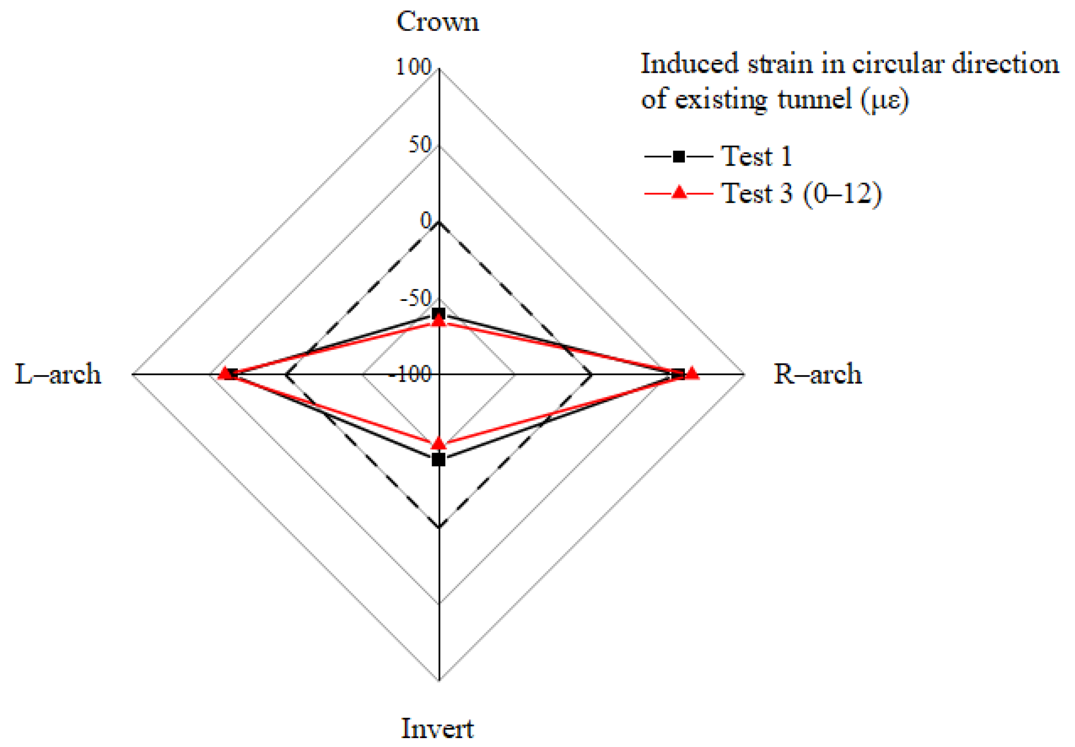
Figure 13 exclusively exhibits the deformation pattern of circular strain resulting from excavation in tests 1 and 3. Positive and negative values in the figure denoted tensile strain and compressive strain, respectively. Due to the strain measuring instrument failure, the strain data for the other tests could not be successfully recorded. As the tunnel was located on one side of the excavation, there was asymmetric stress release and shear on the tunnel cross-section. The overall strain shape conformed to the horizontal ellipsoidal deformation model of the tunnel. The right shoulder and arch of the tunnel were in the closest proximity to the excavation, resulting in a substantial release of stress. Tensile and compressive strains were maximized along the horizontal and vertical directions of the tunnel, respectively, with the right and left shoulder of the tunnel experiencing tensile strain. In contrast, compressive strain occurred at the crown and invert of the tunnel. By comparison, it could be observed that the addition of partition piles in test 3 actually increased the circular strain of the tunnel, consistent with the pattern of the displacement control effects of partition piles.
4. Summary and Conclusions
This study delved into the impacts of pile length and the top burial depth of piles on tunnel deformation induced by excavation, employing partition piles in two-dimensional centrifuge simulation tests. The primary findings can be summarized as follows:
- (1)
- The horizontal displacement of the retaining wall exhibited a cantilever-type displacement. In the control group, The horizontal displacement at the wall’s top section was approximately 1.04% times the excavation depth. After adding partition piles, the maximum horizontal displacement decreased by up to 10.6%.
- (2)
- The ground settlement behind the wall exhibited its maximum intensity in the immediate proximity to the retaining wall, gradually diminishing with the increasing distance from the retaining structure. In the control group, the maximum ground settlement reached 1.1% times the excavation depth. The addition of partition piles reduced ground settlement near the wall by up to 40.1%.
- (3)
- The complete deformation of the tunnel exhibited an approximate horizontal elliptical distortion, where the greatest horizontal displacement transpired at the right shoulder of the tunnel, and the maximum vertical displacement unfolded at the right arch of the tunnel. The introduction of partition piles resulted in a 36.7% reduction in the maximum horizontal displacement and a 31.8% decrease in the maximum vertical displacement of the tunnel.
- (4)
- The impact of partition pile parameters on the control efficacy of retaining wall displacement, ground surface settlement, and tunnel rigid displacement was broadly consistent. Increasing the length of the piles led to a deterioration of the control effect. The control effectiveness of partition piles could be further enhanced by increasing the top burial depth of the piles, but when it was too large and exceeded its critical value, the improvement effect of the top burial depth of piles on partition piles diminished.
- (5)
- In view of the effectiveness of the partition pile in controlling tunnel deformation mentioned above, further research should be conducted to optimize the control effect of the partition pile. Finding the optimal solution of the top burial depth of the pile in the subsequent studies will be a key direction. This will facilitate a deeper exploration of the mechanisms underlying the deformation control effects of partition piles concerning pile length and top burial depth of the pile. Subsequently, numerical simulations will be conducted to draw the deformation control zones of partition piles under various conditions. It will have positive implications for future excavation projects near existing tunnels.
Author Contributions
Conceptualization, Y.D. (Yiming Du); methodology, Y.D. (Yiming Du), B.W. and Y.D. (Yu Diao); software, B.W., H.Z., Y.S. and X.Z.; investigation, Y.D. (Yiming Du) and B.W.; data curation, B.W.; writing—original draft preparation, Y.D. (Yiming Du); writing—review and editing, B.W. and Y.D. (Yu Diao); funding acquisition, Y.D. (Yiming Du). All authors have read and agreed to the published version of the manuscript.
Funding
This research was funded by the National Natural Science Foundation of China (grant number: 52008293).
Institutional Review Board Statement
Not applicable.
Informed Consent Statement
Not applicable.
Data Availability Statement
Data are contained within the article.
Conflicts of Interest
The authors declare no conflict of interest.
References
- Wang, F.; Zhang, D.M.; Zhu, H.H.; Huang, H.W.; Yin, J.H. Impact of overhead excavation on an existing shield tunnel: Field monitoring and a full 3D finite element analysis. Cmc-Comput. Mater. Con. 2013, 34, 63–81. [Google Scholar]
- Sun, H.S.; Chen, Y.D.; Zhang, J.H.; Kuang, T.S. Analytical investigation of tunnel deformation caused by circular foundation pit excavation. Comput. Geotech. 2019, 106, 193–198. [Google Scholar] [CrossRef]
- Liang, R.Z.; Wu, J.; Sun, L.W.; Shen, W.; Wu, W.B. Performances of adjacent metro structures due to zoned excavation of a large-scale basement in soft ground. Tunn. Undergr. Space Technol. 2021, 117, 104123. [Google Scholar] [CrossRef]
- Guo, P.P.; Liu, F.F.; Lei, G.; Li, X.; Zhu, C.W.; Wang, Y.X.; Lu, M.M.; Cheng, K.; Gong, X.N. Predicting response of constructed tunnel to adjacent excavation with dewatering. Geofluids 2021, 2021, 5548817. [Google Scholar] [CrossRef]
- Huang, X.; Schweiger, H.F.; Huang, H.W. Influence of deep excavations on nearby existing tunnels. Int. J. Geotech. 2013, 13, 170–180. [Google Scholar] [CrossRef]
- Gao, G.Y.; Gao, M.; Yang, C.B.; Yu, Z.S. Influence of deep excavation on deformation of operating metro tunnels and countermeasures. Chin. J. Geotech. Eng. 2010, 32, 453–459. [Google Scholar]
- Hu, Z.F.; Yue, Z.Q.; Zhou, J.; Tham, L.G. Design and construction of a deep excavation in soft soils adjacent to the Shanghai Metro tunnels. Can. Geotech. J. 2003, 40, 933–948. [Google Scholar] [CrossRef]
- Chang, C.T.; Sun, C.W.; Duann, S.W.; Hwang, R.N. Response of a taipei rapid transit system (TRTS) tunnel to adjacent excavation. Tunn. Undergr. Space Technol. 2001, 16, 151–158. [Google Scholar] [CrossRef]
- Doležalová, M. Tunnel complex unloaded by a deep excavation. Comput. Geotech. 2001, 28, 469–493. [Google Scholar] [CrossRef]
- Ng, C.W.W.; Shi, J.W.; Chen, Y.H. Three-dimensional centrifuge modelling of basement excavation effects on an existing tunnel in dry sand. Can. Geotech. J. 2013, 50, 874–888. [Google Scholar] [CrossRef]
- Huang, X.; Huang, H.W.; Zhang, D.M. Centrifuge modelling of deep excavation over existing tunnels. Proc. Inst. Civ. Eng.-Geotech. Eng. 2014, 167, 3–18. [Google Scholar] [CrossRef]
- Chen, R.P.; Liu, S.L.; Meng, F.Y.; Ye, J.N.; Zhu, B. Centrifuge modelling of excavation effects on a nearby tunnel in soft clay. Chin. J. Geotech. Eng. 2020, 42, 1132–1138. [Google Scholar]
- Sharma, J.S.; Hefny, A.M.; Zhao, J.; Chan, C.W. Effect of large excavation on deformation of adjacent MRT tunnels. Tunn. Undergr. Space Technol. 2001, 16, 93–98. [Google Scholar] [CrossRef]
- Shi, J.W.; Fu, Z.Z.; Guo, W.L. Investigation of geometric effects on three-dimensional tunnel deformation mechanisms due to basement excavation. Comput. Geotech. 2019, 106, 108–116. [Google Scholar] [CrossRef]
- Shi, J.W.; Ng, C.W.W.; Chen, Y.H. Three-dimensional numerical parametric study of the influence of basement excavation on existing tunnel. Comput. Geotech. 2015, 63, 146–158. [Google Scholar] [CrossRef]
- Zhang, Z.G.; Huang, M.S.; Wang, W.D. Evaluation of deformation response for adjacent tunnels due to soil unloading in excavation engineering. Tunn. Undergr. Space Technol. 2013, 38, 244–253. [Google Scholar] [CrossRef]
- Zhang, H.B.; Chen, J.J.; Fan, F.; Wang, J.H. Deformation monitoring and performance analysis on the shield tunnel influenced by adjacent deep excavations. J. Aerospace. Eng. 2017, 30, B4015002. [Google Scholar] [CrossRef]
- Shi, C.H.; Cao, C.Y.; Lei, M.F.; Peng, L.M.; Ai, H.J. Effects of lateral unloading on the mechanical and deformation performance of shield tunnel segment joints. Tunn. Undergr. Space Technol. 2016, 51, 175–188. [Google Scholar] [CrossRef]
- Shen, H.; Luo, X.Q.; Li, Y.; Pang, B.; Yang, D.C. Numerical simulation and analysis of influence of deep excavation on adjacent subway station. Chin. J. Geotech. Eng. 2011, 7, 1018–1023, 1028. [Google Scholar]
- Meissner, S.; Kies, M.; Berger, A. Complex excavation and foundation variants in a subway protection zone in Frankfurt. Geotechnik 2023, 46, 38–47. [Google Scholar]
- Ng, C.W.W.; Shi, J.W.; Masin, D.; Sun, H.S.; Lei, G.H. Influence of sand density and retaining wall stiffness on three-dimensional responses of tunnel to basement excavation. Can. Geotech. J. 2015, 52, 1811–1829. [Google Scholar] [CrossRef]
- Diao, Y.; Li, P.J.; Huang, J.Y.; Liu, S.; Guo, X.; Hu, Q.S. Effects of environmental factors on mechanical properties of biomimetic mineralized mortar. J. Build. Eng. 2023, 66, 105850. [Google Scholar] [CrossRef]
- Diao, Y.; Yang, C.; Huang, J.Y.; Liu, S.; Guo, X.; Pan, W.Q. Preparation and solidification mechanism of biomimetic mineralized cement using L-Asp as crystal modifier. J. Mater. Res. Technol. 2023, 24, 7756–7770. [Google Scholar] [CrossRef]
- Huang, J.Y.; Diao, Y.; Zheng, G.; Su, Y.M.; Wang, M.H.; Pan, W.Q.; Chen, H. Horizontal Deformation Efficiency of a Pile Controlled by the Capsuled Expansion Technique: A Field Trial and Numerical Analysis. Int. J. Geomech. 2024, 24, 04023262. [Google Scholar] [CrossRef]
- Wu, H.N.; Lan, G.Z.; Liu, Y.; Chen, R.P.; Meng, F.Y.; Xu, X.P. Field performance of an anti-uplift portal frame in control of the tunnel uplift induced by overlying excavation. Tunn. Undergr. Space Technol. 2023, 132, 104908. [Google Scholar] [CrossRef]
- Asano, T.; Ishihara, M.; Kiyota, Y.; Kurosawa, H.; Ebisu, S. An observational excavation control method for adjacent mountain tunnels. Tunn. Undergr. Space Technol. 2003, 18, 291–301. [Google Scholar] [CrossRef]
- Zhao, Y.R.; Chen, X.S.; Hu, B.; Wang, P.H.; Li, W.S. Evolution of tunnel uplift induced by adjacent long and collinear excavation and an effective protective measure. Tunn. Undergr. Space Technol. 2023, 131, 104846. [Google Scholar] [CrossRef]
- Chen, R.P.; Meng, F.Y.; Li, Z.C.; Ye, Y.H.; Ye, J.N. Investigation of response of metro tunnels due to adjacent large excavation and protective measures in soft soils. Tunn. Undergr. Space Technol. 2016, 58, 224–235. [Google Scholar] [CrossRef]
- He, M.C.; Sui, Q.R.; Li, M.N.; Wang, Z.J.; Tao, Z.G. Compensation excavation method control for large deformation disaster of mountain soft rock tunnel. Int. J. Min. Sci. Technol. 2022, 32, 951–963. [Google Scholar] [CrossRef]
- Bilotta, E.; Russo, G. Use of a line of piles to prevent damages induced by tunnel excavation. J. Geotech. Geoenviron. Eng. 2011, 137, 254–262. [Google Scholar] [CrossRef]
- Ma, S.K.; Fu, X.X.; Lu, H.; Huang, Z.; Zhang, J.B. A combined support method of partition pile and diaphragm wall for protection of buildings adjacent to deep excavation. Arab. J. Geosci. 2021, 14, 2005. [Google Scholar] [CrossRef]
- Ying, H.W.; Li, T.; Yang, Y.W. Analysis on the effect and engineering application of protecting adjacent buildings with partition wall of deep excavation. Chin. J. Geotech. Eng. 2011, 33, 1123–1128. [Google Scholar]
- Song, G.Y.; Marshall, A.M. Centrifuge study on the use of protective walls to reduce tunnelling-induced damage of buildings. Tunn. Undergr. Space Technol. 2021, 115, 104064. [Google Scholar] [CrossRef]
- Rampello, S.; Fantera, L.; Masini, L. Efficiency of embedded barriers to mitigate tunnelling effects. Tunn. Undergr. Space Technol. 2019, 89, 109–124. [Google Scholar] [CrossRef]
- Zheng, G.; Wang, F.J.; Du, Y.M.; Diao, Y.; Lei, Y.W.; Cheng, X.S. The efficiency of the ability of isolation piles to control the deformation of tunnels adjacent to excavations. Int. J. Civ. Eng. 2018, 16, 1475–1490. [Google Scholar] [CrossRef]
- Bilotta, E. Use of diaphragm walls to mitigate ground movements induced by tunnelling. Géotechnique 2008, 58, 143–155. [Google Scholar] [CrossRef]
- Chen, R.P.; Ashraf, A.; Meng, F.Y. Centrifuge model test study on the influence of excavation on side tunnel and the action of partition wall. Chin. J. Geotech. Eng. 2018, 40, 6–11. [Google Scholar]
- Zheng, G.; Du, Y.M.; Diao, Y. Optimization analysis of deformation control of existing tunnel outside excavation by partition pile. Chin. J. Rock Mech. Eng. 2015, 34, 3499–3509. [Google Scholar]
- Chen, R.P.; Meng, F.R.; Li, Z.C.; Ye, Y.H.; Hu, Q. Excessive displacement and protective measures of metro tunnel near deep excavation. J. Zhejiang Univ. 2016, 50, 856–863. [Google Scholar]
- Bai, Y.; Yang, Z.H.; Jiang, Z.W. Key protection techniques adopted and analysis of influence on adjacent buildings due to the Bund Tunnel construction. Tunn. Undergr. Space Technol. 2014, 41, 24–34. [Google Scholar] [CrossRef]
- Wang, B.Y.; Du, Y.M.; Diao, Y.; Zhao, X.Y. Numerical optimization of mini centrifuge modelling test design of excavation unloading influence on existing tunnel controlled by partition piles. Sustainability 2023, 15, 8353. [Google Scholar] [CrossRef]
Figure 1.
Displacement curves of soil in cases with and without isolation piles [35].
Figure 1.
Displacement curves of soil in cases with and without isolation piles [35].

Figure 2.
Frontal photo of centrifuge.

Figure 3.
Cross-section of the model box and photo of test 5. (a) Cross-section of the model box. (b) Photo of test 5.
Figure 3.
Cross-section of the model box and photo of test 5. (a) Cross-section of the model box. (b) Photo of test 5.
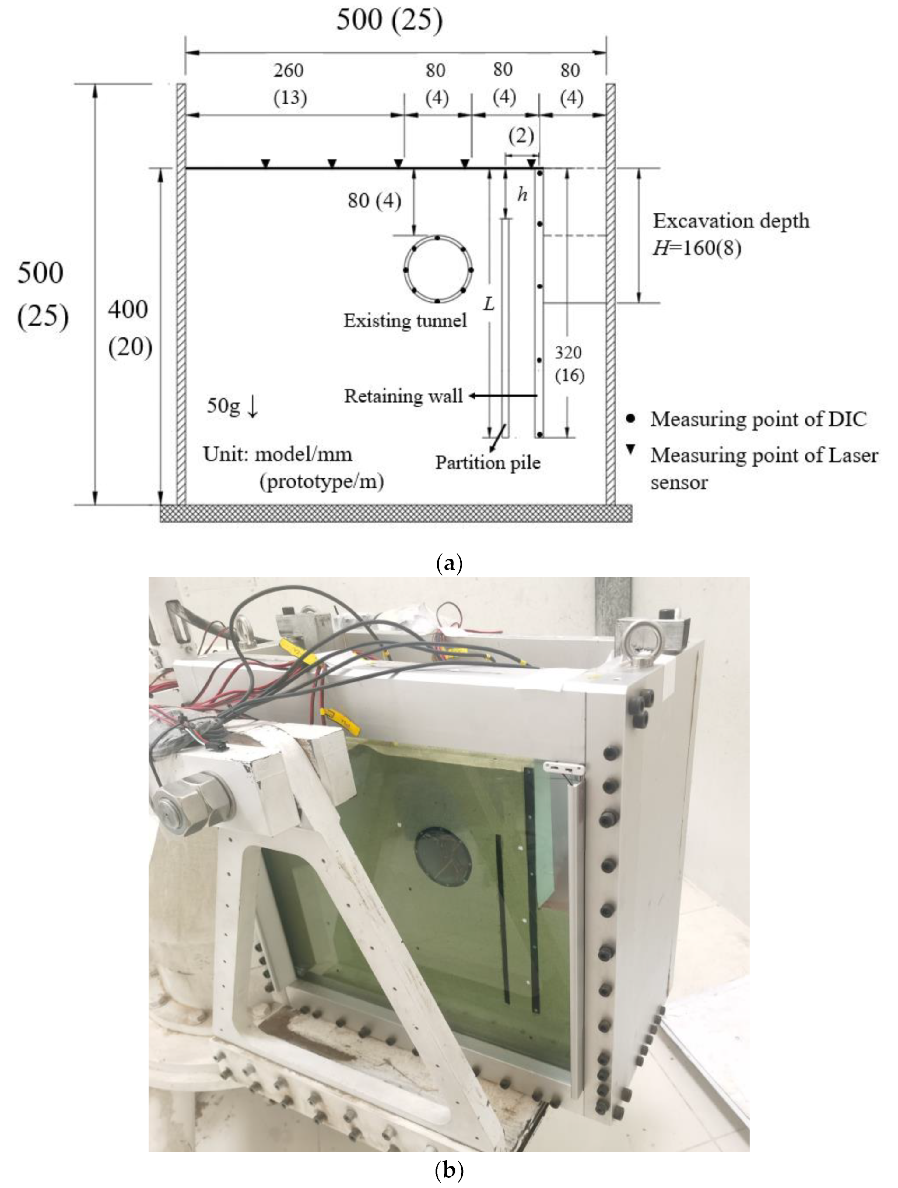
Figure 4.
Heavy liquid discharge system.
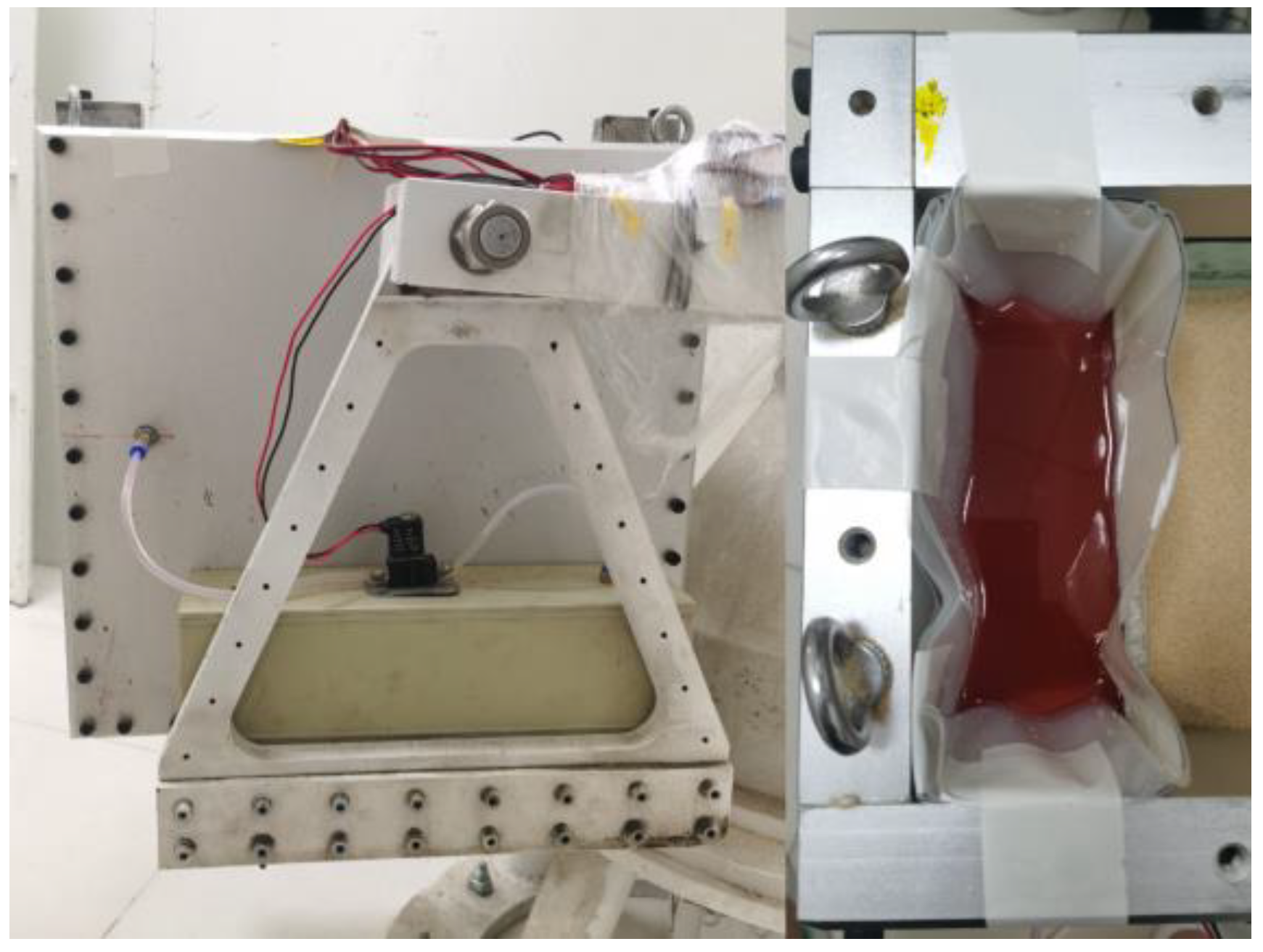
Figure 5.
Displacement observation system with DIC.
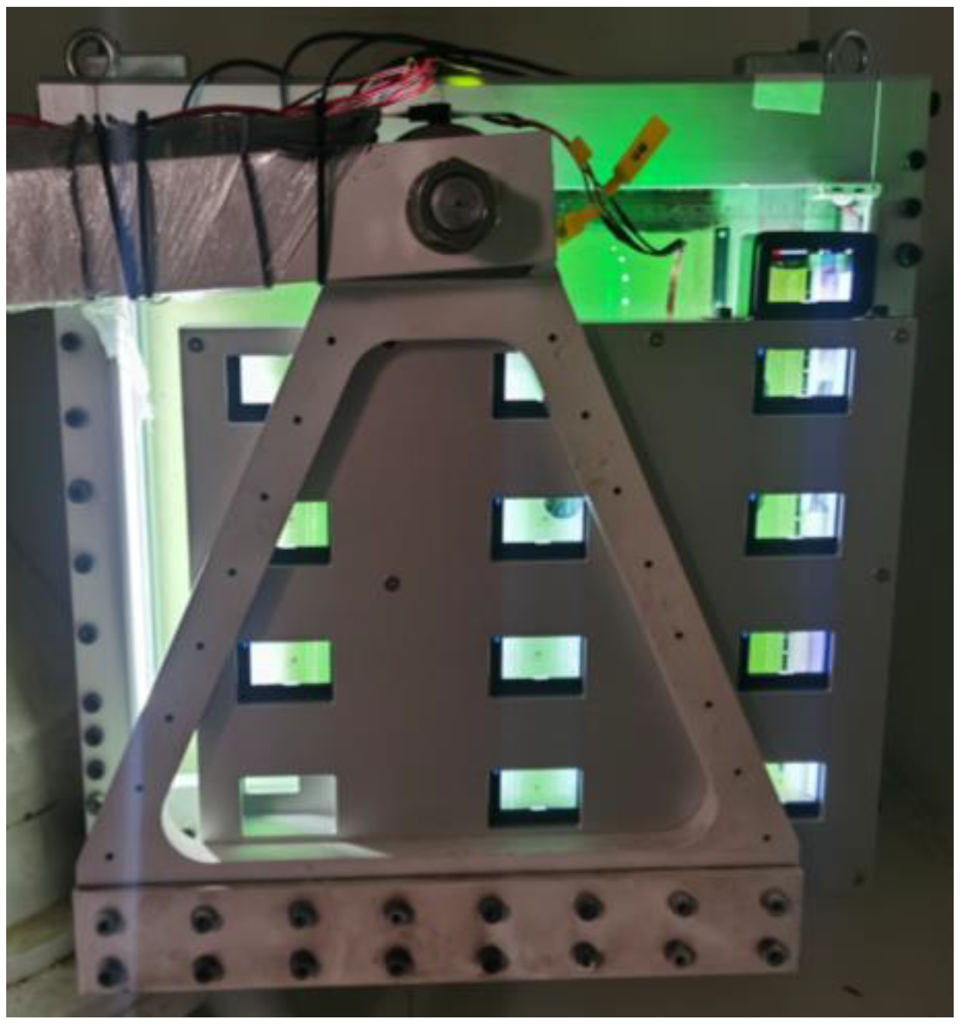
Figure 6.
Distribution of tunnel strain gauges.
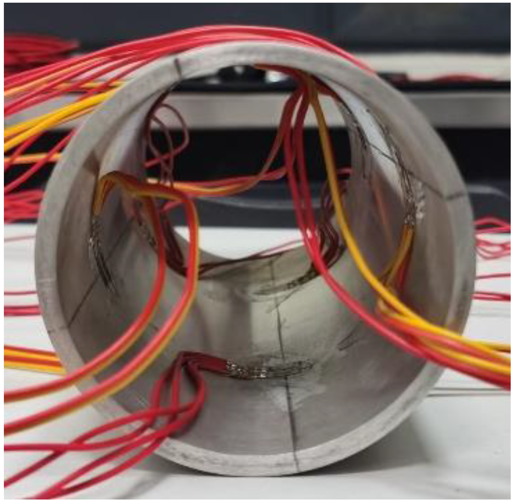
Figure 7.
Arrangement of laser sensors.
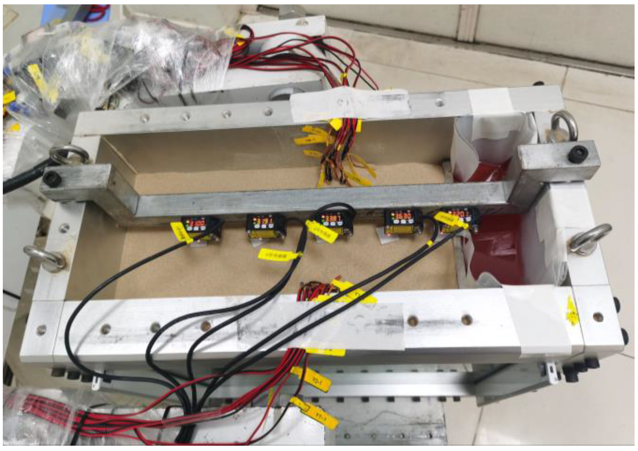
Figure 8.
Horizontal displacement of the retaining wall, and A and B respectively refer to the number in parentheses in the figure. (a) Comparison group of pile length. (b) Comparison group of pile length.
Figure 8.
Horizontal displacement of the retaining wall, and A and B respectively refer to the number in parentheses in the figure. (a) Comparison group of pile length. (b) Comparison group of pile length.
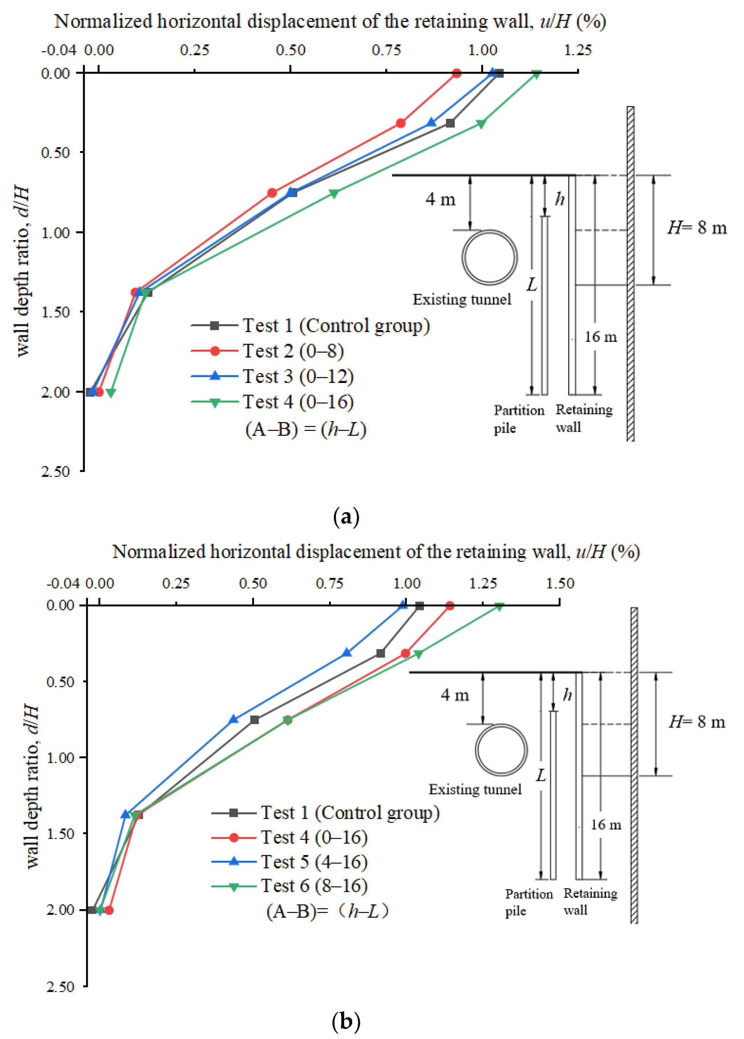
Figure 9.
Ground surface settlement behind retaining wall, and A and B respectively refer to the number in parentheses in the figure. (a) Comparison group of pile length. (b) Comparison group of pile length.
Figure 9.
Ground surface settlement behind retaining wall, and A and B respectively refer to the number in parentheses in the figure. (a) Comparison group of pile length. (b) Comparison group of pile length.

Figure 10.
Horizontal displacement of the tunnel, and A and B respectively refer to the number in parentheses in the figure. (a) Comparison group of pile length. (b) Comparison group of pile length.
Figure 10.
Horizontal displacement of the tunnel, and A and B respectively refer to the number in parentheses in the figure. (a) Comparison group of pile length. (b) Comparison group of pile length.

Figure 11.
Vertical displacement of the tunnel, and A and B respectively refer to the number in parentheses in the figure. (a) Comparison group of pile length. (b) Comparison group of pile length.
Figure 11.
Vertical displacement of the tunnel, and A and B respectively refer to the number in parentheses in the figure. (a) Comparison group of pile length. (b) Comparison group of pile length.

Figure 12.
Convergence deformation of tunnel.

Figure 13.
Induced strain in circular direction of existing tunnel.

Table 1.
Experimental design scheme.
| Test Number | Length of Pile (L)/m | Top Burial Depth of Pile (h)/m |
|---|---|---|
| 1 (Control group) | 0 | 0 |
| 2 | 8 | 0 |
| 3 | 12 | 0 |
| 4 | 16 | 0 |
| 5 | 16 | 4 |
| 6 | 16 | 8 |
Table 2.
Centrifuge modelling parameter similarity ratio (model/prototype).
| Parameter | Symbol | Dimension | Similarity Ratio |
|---|---|---|---|
| Gravitational acceleration | g | L·T−2 | 50 |
| Geometric dimension | L | L | 1/50 |
| Displacement | D | L | 1/50 |
| Density | ρ | M·L−3 | 1 |
| Time | T | T | 1/502 |
| Strain | ε | - | 1 |
| Stress | σ | M·T−2·L−1 | 1 |
| Elastic modulus | E | M·T−2·L−1 | 1 |
| Bending stiffness | EI | M·T−2·L3 | 1/504 |
| Bending stiffness per unit length | EI | M·T−2·L2 | 1/503 |
| Bending moment | M | M·T−2·L2 | 1/503 |
| Bending moment per unit length | M | M·T−2·L | 1/502 |
Table 3.
Parameters of structural components.
| Structural Components | Parameters | Model Size (mm) | Prototype Size (m) |
|---|---|---|---|
| Retaining wall | Thickness | 10 | 0.5 |
| Length | 320 | 16 | |
| Width | 200 | 10 | |
| Tunnel | Outer Diameter | 80 | 4 |
| Thickness | 4 | 0.2 | |
| Width | 200 | 10 | |
| Partition wall | Thickness | 6 | 0.3 |
| Length | 160, 240, 320 | 8, 12, 16 | |
| Width | 200 | 10 |
Disclaimer/Publisher’s Note: The statements, opinions and data contained in all publications are solely those of the individual author(s) and contributor(s) and not of MDPI and/or the editor(s). MDPI and/or the editor(s) disclaim responsibility for any injury to people or property resulting from any ideas, methods, instructions or products referred to in the content. |
© 2023 by the authors. Licensee MDPI, Basel, Switzerland. This article is an open access article distributed under the terms and conditions of the Creative Commons Attribution (CC BY) license (https://creativecommons.org/licenses/by/4.0/).
Share and Cite
MDPI and ACS Style
Du, Y.; Wang, B.; Diao, Y.; Zhao, H.; Zhao, X.; Su, Y. Centrifuge Modelling of the Impact of Excavation with Partition Piles on Adjacent Existing Tunnel. Appl. Sci. 2023, 13, 13064. https://doi.org/10.3390/app132413064
AMA Style
Du Y, Wang B, Diao Y, Zhao H, Zhao X, Su Y. Centrifuge Modelling of the Impact of Excavation with Partition Piles on Adjacent Existing Tunnel. Applied Sciences. 2023; 13(24):13064. https://doi.org/10.3390/app132413064
Chicago/Turabian StyleDu, Yiming, Bingyi Wang, Yu Diao, Haotian Zhao, Xiangyu Zhao, and Yiming Su. 2023. "Centrifuge Modelling of the Impact of Excavation with Partition Piles on Adjacent Existing Tunnel" Applied Sciences 13, no. 24: 13064. https://doi.org/10.3390/app132413064
Note that from the first issue of 2016, this journal uses article numbers instead of page numbers. See further details here.