
Analysis of Performance Improvement of Passenger Car Synchronous Homopolar Generator with the Addition of Ferrite Magnets


Department of Electrical Engineering, Ural Federal University, 620002 Yekaterinburg, Russia
*
Author to whom correspondence should be addressed.
Appl. Sci. 2023, 13(6), 3990; https://doi.org/10.3390/app13063990
Submission received: 17 February 2023
/
Revised: 18 March 2023
/
Accepted: 19 March 2023
/
Published: 21 March 2023
(This article belongs to the Topic Advanced Electrical Machines and Drives Technologies)
Abstract
:Featured Application
The research findings can be applied in the design of generators of various vehicles, in particular synchronous homopolar generators.
Abstract
Electric machines with hybrid excitation have increased torque density while maintaining a wide range of speed control. This article presents the results of the optimal design of a synchronous homopolar generator (SHG) with ferrite magnets on the rotor and excitation winding on the stator for passenger cars. The use of ferrite magnets on the rotor of a synchronous homopolar generator makes it possible to use the stator surface more efficiently, which in turn increases energy efficiency and reduces the dimensions of the generator. At the same time, the excitation winding on the stator provides a reliable brushless design and the ability to control the excitation flux. The problem of long-time calculation of the three-dimensional SHG structure, which is especially relevant when using multi-iterative computer optimization, is solved by using the computationally efficient Nelder-Mead method and a simplified SHG model using two-dimensional finite element analysis. It is also clear that the low torque ripple of SHG with ferrite magnets with two stator-rotor stack combinations (SRSC) is largely provided by the fact that the torque ripples of individual SRSCs are in antiphase. The problem of considering the magnetic properties of magnetic core sections made of structural low-carbon steel is discussed. It has been found that with an increase in both the saturation level of the magnetic circuit and the magnetomotive force (MMF) of the SHG excitation winding, resistance to irreversible demagnetization of ferrite magnets on the rotor can be increased by increasing their height. In addition, it is shown that there is a significant increase in performance when using the hybrid excitation, in comparison with the conventional SHG design without magnets.
1. Introduction
1.1. Advantages of Synchronous Machines with Electric and Hybrid Excitation without Rare Earth Magnets
Generators with rare-earth permanent magnets are widely used when operating with a controlled rectifier [1]. At the same time, many researchers are looking for alternative designs that do not contain rare earth magnets, since these magnets are expensive, and their use makes the manufacturer dependent on a few suppliers. The price of rare earth magnets can fluctuate greatly and change several times, depending on the state of the international market. The extraction of raw materials for rare earth magnets is harmful to the environment [2]. In addition, electric machines with rare earth magnets have disadvantages in operation. Nd-Fe-B rare earth magnets are not well suited for high temperature applications due to their tendency to irreversibly demagnetize at temperatures above 120 °C and strong demagnetizing fields. While more temperature resistant Sm-Co magnets are available, due to the high cost and difficulty in machining, they are typically only used in aerospace systems [3].
The electrical conductivity of rare earth magnets is relatively high, therefore, at a high operating frequency, large eddy currents are induced in rare earth magnets, which leads to their high heating and complicates their use in high-speed applications. Magnetomotive force (MMF) from permanent magnets is uncontrollable and cannot be turned off in emergency situations, which complicates the use of the machines with rare earth magnets in many applications [4]. An alternative is wound rotor electrically excited synchronous generators (WRSG). However, their conventional designs cannot be used in many applications due to the presence of slip rings and brushes feeding the excitation winding on the rotor, which are subject to rapid wear [5]. In addition, the excitation winding on the rotor produces significant losses, which makes it difficult to cool the WRSG.
In a number of applications, for example, for turbo generators connected directly to the grid and for electric aircraft, wound rotor synchronous generators with a brushless exciter are used [6,7]. However, the use of a brushless exciter leads to an increase in the cost, size, and weight compared to traditional generators. In addition, in railway applications, the low resistance of the brushless exciter to shaking and shock loads, as well as the complexity of repairing a generator with such an exciter, are critical. Another alternative with an electrically excited brushless design is synchronous homopolar machines (SHMs).
1.2. Overview of Literature on the Design of Synchronous Homopolar Machines
On non-fully electrified rail lines, undercar generators can be used to power passenger cars. Often, synchronous homopolar generators (SHGs) without permanent magnets with concentrated excitation coils on the stator are used in this application, due to their relatively high performance and highly reliable brushless design that is resistant to shaking and shock loads and to the absence of windings on the rotor [8]. SHMs also find uses in other applications such as traction drives, flywheel storage, wind turbines, on-board generators, and welding generators [9,10,11,12,13]. In addition, the excitation current of the SHG is adjustable, as in a conventional electrically excited generator.
The analysis of the magnetic field of the SHG and, consequently, its optimization, is complicated by the complex three-dimensional configuration of its magnetic core. In some parts of the machine, the flux flows in the axial direction, and in others do so in the transverse plane (in the tangential and radial directions) and changes its direction to an axial one when moving from the laminated parts to the solid stator housing or magnetic sleeve on the rotor shaft.
The applicability of the traditional two-dimensional finite element model is limited, due to the three-dimensional nature of the magnetic field of the SHG. Researchers have developed a number of models that take into account the three-dimensional structure of the SHG magnetic field using one-dimensional magnetic circuits [14,15], models based on the two-dimensional finite element method (FEM) [16,17], and three-dimensional FEM models [18,19]. In [17], a technique for modeling the SGM was presented, which considers the three-dimensional structure of the magnetic field within the framework of a two-dimensional model by introducing an additional term into the equations of the vector magnetic potential, and jointly solving them with the one-dimensional equation of the axial magnetic circuit of the excitation flux. An experimental verification of this technique is carried out.
In [8,9,14,16,19,20,21,22], SHM performance analysis for generators and flywheel energy storage applications is carried out. Due to the complexity of the configuration of the magnetic system, many different methods for calculating the performance of SHG have been proposed. In [8], an SHG design using the 2D FEA mode was considered in order to improve the performance properties of a mass-produced undercar generator. Manual optimization of the number of rotor teeth, as well as the parameters of the rotor and stator teeth, was applied. Through experimental verification it is shown that the optimized design has a higher no-load EMF value. In [9], modeling of the transient process in a low-power train-lighting alternator based on SHM is considered, taking into account the eccentricity of the rotor. In [19], the analysis of a low-power high-speed SHM with an external rotor is considered, the design of which is carried out using analytical expressions. The SHM performance at idle and at rated load is calculated using 3D FEA. In [14,16], an equivalent 2D finite element SHM model with virtual excitation on the rotor is presented, which is verified using 3D FEA and an experimental study. In [20], the design of a high-speed high-power motor/generator based on SHM is considered. The layout of a superconducting excitation winding, and a water-cooled armature winding made of Litz wire is described. For performance analysis, an approximate SHM model is used in which the magnetic field is analyzed using a 2D finite element analysis in a plane containing the axis of rotation of the machine. In [18], analysis using 3D FEM and manual optimization of the no-load electromotive force (EMF) for a three-phase SHG with a speed control range of 500–7000 rpm are presented. Characteristics of the SHM are evaluated with different combinations of stator and rotor teeth: 9/6, 15/10 and 18/12. An experimental verification was provided. In [23], the optimization of the mass and dimensions of an SHG using a genetic method and a lumped parameter model is presented. It is noted that the use of 3D FEA in SHM optimization is complicated by a large calculation time. In [24,25], methods for analyzing transient processes in SHGs using ordinary differential equations are proposed. In [26,27], methods for analyzing the thermal state of an SHG are proposed. In [28], the features of SHG modeling with a superconducting excitation winding are discussed.
Despite the SHM advantages, the losses in SHM with the same dimensions are significantly higher than in conventional WRSG due to less efficient use of the rotor surface [5]. Since ferrite magnets are much cheaper than rare earth magnets, have a wider range of suppliers and are environmentally friendly, it is attractive to improve the performance of the SHG by adding ferrite magnets. Ferrite magnets are also well suited for use in high-temperature applications and have extremely low electrical conductivity, which makes them suitable for high-speed applications [22].
In [21,22], a design of an SHG with ferrite magnets for powering passenger cars is presented. It is shown that the addition of ferrite magnets makes it possible to increase the efficiency and reduce the mass and dimensions of the SHG. In [21], the calculation of the electromotive force (EMF) of SHG with ferrite magnets at idle is carried out; however, the calculation of the performances under load and the analysis of irreversible demagnetization were not carried out. In [22], a design of SHG with ferrite magnets is described in more detail.
1.3. The Problem and Aim of the Study
The review of the literature shows that the performance optimization of SHG with ferrite magnets under load has never been presented.
The purpose of the study is to increase the performance and reduce the weight and dimensions of synchronous homopolar generators for passenger cars operated on non-electrified and partially electrified railways. The novelty of this article lies in the development of a technique for optimizing the on-load performance of SHG with ferrite magnets as a railway undercar generator. The cost function is constructed, and a relevant example of the optimized design is obtained. The optimization of the SHG with ferrites minimizes losses, semiconductor rectifier current, torque ripple, and the volume of irreversibly demagnetized permanent magnets. In addition, a comparative analysis of the characteristics of the optimized SHG with ferrite magnets and an SHG without permanent magnets, the optimized characteristics of which were obtained in [29], is presented.
2. Main Features of the Considered Design of the SHG with Ferrite Magnets
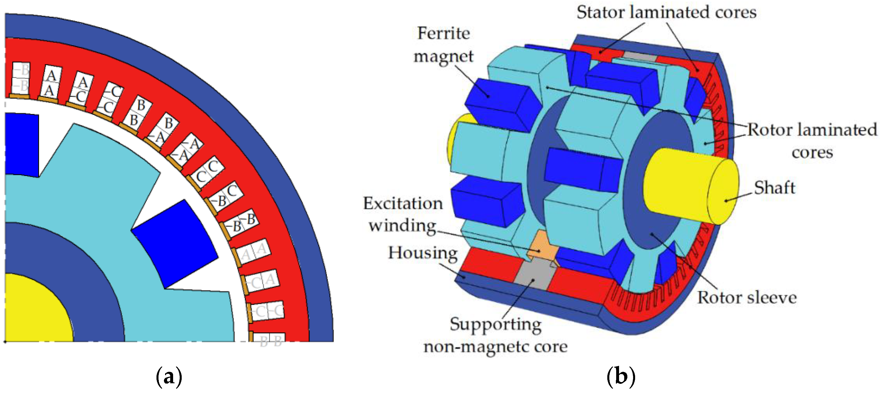
As Figure 1 shows, the SHG has two laminated steel stator-rotor stack combinations (SRSCs). In the axial direction, the excitation magnetic flux is transmitted through the non-laminated stator housing, in which the stator laminated stacks are installed, and through the rotor sleeve, on which the laminated rotor stacks are installed. The three-phase armature winding is placed in 54 stator slots and has 12 poles with the number of slots per pole and per phase q = 54/(12∙3) = 1.5.
The excitation winding is placed in an axial gap between the two generator SRSCs. The laminated rotor stacks are of salient pole design. The rotor has no windings and has low-energy ferrite magnets in the slots of the rotor stacks. Each rotor lamination has six teeth. The tooth shift of the two rotor laminations relative to each other is 30 mechanical degrees.
Figure 2 shows the scheme for rectifying the output current of the generator to the network of the car. The generator feeds the network of the car, and also recharges the battery. The rectifier uses controlled transistor switches that provide vector control of the generator armature winding current. The concentric coil of the excitation winding is located between the pairs of rotor and stator stacks and is fixed on the supporting non-magnetic core. The DC-link voltage (close to the maximum amplitude of the line-to-line voltage of the generator) must not exceed 116 V. The semiconductor converter also includes a single-phase breaker for powering the excitation winding of the generator.
At the preliminary calculations, it was established that without parallel paths, each layer of the armature winding should contain one turn. However, this led to large eddy current losses in the armature winding, so the number of parallel paths was chosen to be six, that is, equal to the number of pole pairs.
3. SHG Mathematical Model
The SHG magnetic core has two SRSCs linked to each other in the axial direction by the stator housing and the rotor sleeve made of non-laminated low-carbon steel. The excitation winding fixed on the stator induces the excitation flux, which passes through the SRSCs, the stator sleeve on the rotor shaft, and the stator housing [8,30] (see Figure 3). The modulation of the magnetic field by the teeth of the rotor allows this magnetic flux to interact with the poles of the armature winding on the stator. In the absence of magnets, only half of the poles would be involved in the torque production. The addition of permanent magnets between the teeth of the rotor makes all poles of the armature winding to usable [31,32].
The developed mathematical model consists of a set of g boundary 2D magnetostatic problems for a magnetic field in the cross section of an SRCS and a magnetic circuit equation with lumped parameters in the axial direction. The range of considered rotor position angles is chosen taking into account the symmetry with respect to a shift by a third of the electric period and cyclic phase permutation and is equal to a third of the electric period. One third of the electric period is divided into g sections and boundary value problems are considered for the beginning of each section. In this study, g = 24.
As in conventional electric machines, the magnetic field in a good approximation can be assumed to be uniform along the axis and lying in the transverse plane. Therefore, the equations traditional for 2D problems of magnetostatics are solved [17]:
where Jz is the z-component of the current density, which is not equal to zero only in the stator slots filled with a winding; Bx and By are the components of the magnetic flux density; Hx and Hy are the components of the magnetic field.
A distinctive feature of SHM is the presence of a magnetic monopole, i.e., excitation flux flowing in on the inner boundary of the rotor and flowing out of the outer boundary of the stator (or vice versa). Then, the general solution of the Gauss law for magnetism (1) can be expressed as follows:
where Az is the z-component of the vector magnetic potential; ϕ is the linear density of the magnetic charge. Only the component of the vector magnetic potential A along the z-axis is different from zero. In these equations, the first terms on the right side of these equations are common for a magnetostatic problem. The second terms determine the linear flux density of the magnetic monopole, which is set based on the following relation:
where Lstator is the total stator laminated stack length.
Φ = ϕ ∙ Lstator/2.
The calculation area is one sector corresponding to the pole pitch of the generator, with periodic boundary conditions PI and PII on the boundaries of this sector, as shown in Figure 4. The change in the rotor angular position is modeled not by changing the geometry of the calculation area, but by changing the connecting boundary condition on a circular line lying in the middle of the air gap between the rotor and stator.
The equations of magnetostatics are complemented by constitutive equations. For the rotor and stator stacks, the magnetization curve H(B) is set. For magnets, the residual magnetic flux density and the magnetic permeability are set. For the areas of the armature winding, the current density is set, and the flux coupled to the winding is calculated, which is necessary to calculate the voltage in the armature winding.
The rotor rotates together with the rotating field, and there are practically no eddy currents in its stack and sleeve. Since the rotor sleeve is ferromagnetic, the normal derivative of Az is equal to zero at the inner boundary of the rotor package (the Neumann boundary condition).
On the contrary, the magnetic flux is frozen into the stator housing, and the normal component of the magnetic flux density at the outer boundary of the stator stack is represented only by the monopole field. Thus, for the outer boundary of the stator stack, the Dirichlet boundary condition Az = 0 is accepted.
Due to the fact that the field is frozen into the stator housing, we will assume that the magnetic charge does not change in time, and when calculating the MMF drop on a pair of rotor and stator stacks, we will use the average value for all boundary value problems. MMF can be calculated as a curvilinear integral of magnetic field along any trajectory from the inner boundary of the rotor stack to the outer boundary of the stator stack. Radial segments can be chosen as such trajectories. However, due to the discreteness of the finite element method, such integrals will have a small accuracy. Therefore, it is better to average over the azimuthal angle the values of these integrals. Therefore, the MMF drop on one pair of rotor and stator stacks is determined by the formula:
where the double integral ∫∫ is taken over the entire computational domain.
The magnetic circuit equation in the axial direction has the form [17]:
where Iexc is the excitation winding current; N is the number of turns of the excitation winding; F is the drop in MMF on one SRCS; Fhousing = λ ∙ Hhousing (Φ/Shousing) is the MMF drop on the stator housing; Fsleeve = λ ∙ Hsleeve (Φ/Ssleeve) is the MMF drop on the rotor sleeve; Hhousing and Hsleeve are the dependences of the magnetic field on the magnetic flux density in the stator housing and in the rotor sleeve, respectively; Shousing and Ssleeve are the cross-sectional areas of the housing and sleeve; λ is the axial distance between the SRCSs.
N ∙ Iexc = 2 ∙ F + Fhousing + Fsleeve,
The torque created by one SRCS and the EMF induced in the armature winding of one SRCS are called nonsymmetrized. The torque and EMF of the whole machine are equal to the sum of the torque and the EMF of each SRCS. To find the torque and EMF of the whole machine, there is no need to calculate them for each SRCS. It is assumed that the torque of the second SRCS is equal to that of the first SRCS, and the EMF is equal to that of the first SRCS with a sign ‘−’ when the rotor is shifted by half the electric period [17]. Further, the torque ripple of the whole machine is referred to as symmetrized torque ripple. The torque ripple as a single SRVS is referred to as nonsymmetrized torque ripple.
The iron loss is a key component of the total loss. Therefore, it is also evaluated for each intermediate design obtained during the optimization, i.e., at each step of optimization (each call of the objective function) based on the solution of g boundary problems. A conventional algorithm for calculating iron losses is used [33].
4. Selection of the Objective Function and Optimization Parameters
Like traction motors, an undercar generator is an electrical machine, operating over a wide range of speeds at a constant required output power. However, in the case of a generator, a constant electrical output is required. The rotational speed of an undercar generator increases along with the velocity of the train. The operating speed range of the considered undercar generator is from 750 to 3450 rpm. The generator must produce about 35 kW in this speed range [34]. In order to simplify the optimization procedure, it was assumed that the mechanical power of the generator does not change and is equal to Pmax = 40 kW > 35 kW in the entire considered speed range, roughly taking into account the generator loss. Two boundary points are considered in the optimization: the speed n1 = 3450 rpm at the torque of Tmax ∙ n2/n1 = 111 N∙m and the speed n2 = 750 rpm at the torque of Tmax = 510 N∙m (Figure 5).
Manufacturers of passenger car generators [34] have been requested to increase their energy efficiency, and it is necessary to limit the reactive current and torque ripple. In addition, in order to avoid the failure of the generator, it is necessary to prevent irreversible demagnetization of the permanent magnets on the rotor.
Thus, the goals of optimization in descending order of importance are to minimize the following quantities:
- Average losses <Ploss> which are estimates as the average losses in the modes with the speeds of 750 rpm and 3450 rpm;
- Upper limit of the phase armature current Iarm;
- Symmetrized torque ripple max(TRsym) in the entire operating speed range;
- Non-symmetrized torque ripple max(TR) in the entire operating speed range;
- Volume of irreversibly demagnetized magnets at maximum current at a speed of 750 rpm.
Structural steel 1010 (non-laminated steel used for the manufacture of machine parts) is the material of non-laminated parts of the magnetic circuit. Since the exact magnetization curve and saturation knee point of this steel are not exactly known and are not specified by the manufacturer to ensure that the drop in the magnetomotive force on the stator housing and rotor sleeve is small compared to the drops on the SRSCs, the flux density in these parts is limited to 1.6 T.
In this study, the single-criterion unconditional Nelder-Mead method is used to optimize the SHG design, which is well known [35] and is included in the basic MATLAB software package (“fminsearch” function).
Since the Nelder-Mead method is a single-criteria method, in order to achieve the set of optimization goals, the objective function is set as the product of individual goals raised to a certain power, reflecting their significance. Since the Nelder-Mead method is an unrestricted method, the constraints are also given as separate multipliers of the objective function. To avoid reducing the size of the simplex too quickly and slowing down or stalling the optimization process as a result, the corresponding multipliers increase rapidly rather than discretely, unless constraint conditions (“soft constraints”) are met. The objective function used is:
where <Ploss> is the average total loss (arithmetic mean of total losses Ploss at the two considered operating points);
max(Iarm) is the maximum armature current that occurs at the 2nd operating point (the maximum torque; 750 rpm); max(TRsym) is the maximum value of the symmetrized torque ripple; max(TR) is the maximum value of the nonsymmetrized torque ripple; Bh is magnetic flux density in the stator housing and rotor sleeve at the 2nd operating point; Sdemag is the area of the demagnetized magnets; Smag is the total area of the magnets. Furthermore, for greater clarity, the natural logarithm (6) is used.
In Equation (6), constants/weights 1, 0.7, 0.025 and 0.01 determine the importance of certain objectives. These values just reflect the approximate relative priority of each of the optimization goals, based on the experience of the authors in designing similar machines. The most important target has a weight of one. The most important optimization objective is to reduce the average loss, so the corresponding <Ploss> multiplier is raised to the highest power. The constant 0.7 means that a 1% reduction in the current at 750 rpm is considered as valuable as a 0.7% reduction in the average loss. The objectives of reducing symmetrized and unsymmetrized torque ripples are substantially less important. The constants 0.025 and 0.01 mean that other things being equal, designs with lower torque ripples are preferable.
The last two multipliers of function (6) set the soft constraints of flux density in non-laminated parts of the magnetic core and the area of irreversibly demagnetized ferrite magnets. The constants 5 and 300 control the steepness of the constraints. Too small values of these constants can lead to constraint violations, i.e., to an unacceptable design. Calculations show that the optimized design satisfies the constraints (flux density in these parts is no more than 1.6 T; demagnetizing force is 3.9 kOe). Too large values cause fast reduction of the volume of the simplex, which slows down optimization.
In order to simplify the optimization procedure, as well as the possibility of using the results for different types of winding wires with different standard sizes (for example as specified in [36]), it is assumed that the number of turns in the layer of the armature winding, as well as the width and height of the wire are arbitrary positive real numbers. The number of turns is selected so as to fit with the amplitude value of the line voltage V3450 in the 40 kW; 3450 rpm (maximum voltage) operating point is equal to 113 V [5]. The number of parallel branches is assumed to be equal to six. The parameters that define the design of the generator are illustrated in Figure 6.
The main unchangeable parameters of the generator are shown in Table 1. Table 2 shows the values of the parameters of the SHG varied during the optimization for the initial design, as well as the design obtained as a result of optimization. Because the Nelder-Mead method is an unconstrained optimization method, ranges of optimization parameters are not provided.
Since the Nelder-Mead method is a local search method, the initial design is not completely random. To obtain the initial design, a manual optimization with several attempts was carried out. The parameters varied manually to achieve better performance, to mitigate the saturation or the violation of the constraints. Some principles used are as follows:
- -
- To mitigate the saturation, the thickness of the most saturated parts of the magnetic core must be increased. For example, to decrease saturation, the most saturated parts of the magnetic core should be thickened;
- -
- To decrease the total loss, it is useful to inspect the losses in individual parts of the machine;
- -
- To decrease the loss in the armature winding or in the excitation one, we can try to increase their cross-section area, etc.
The rotor shaft is made of non-magnetic material. Since the same magnetic flux flows through the stator housing and the rotor sleeve, their cross sections are assumed to be equal. For this reason, a change in the thickness of the stator housing also leads not only to a change in the outer diameter of the stator lamination, but also to a change in the outer diameter of the rotor sleeve.
The net fill factor of the armature slot with copper is assumed to be 0.8. The width wx and the height wy of the rectangular wire of the armature winding, which are taken into account when estimating its DC losses and eddy current losses, include the thicknesses of conductors and insulation [5]:
where ax = 1.51 mm, ay = 1.8 mm, Δw = 0.31 mm take into account the thicknesses of the rectangular busbar insulation and the thickness of the slot insulation.
bp = wx + ax; hp = 2∙(wy + Δw) ∙ Nsec + ay,
When calculating losses in the excitation winding, eddy current losses are not taken into account. At the maximum torque, the angle between the center of the rotor tooth and the stator current vector (“current angle”) is taken unchanged and equal to 0.1 electric radians as shown in Table 1. The current angle at maximum speed is also an optimization parameter as shown in Table 2.
Figure 7 illustrates the order of calculations when calling the objective function F (6). The optimization procedure ‘fminsearch’of MATLAB software, which implements the simplex gradientless Nelder-Mead method [35], is well known, and its details are described in [37].The optimization procedure fminsearch(F, x0) is launched to find the vector x of optimized values of the generator parameters, where x0 is a vector with initial values of the generator parameters (see Table 2).
5. Optimization Progress and Comparative Analysis of the Generator Performances before and after Optimization
As a result of optimization, the value of the objective function (6) converges to a minimum (Figure 8). The volume of the simplex can quickly decrease during optimization, and further optimization slows down. Therefore, after the 180th function call, the Nelder-Mead method was restarted. The optimal solution found was used as the initial approximation. The linear dimensions of the simplex at the restart were reduced by four times compared to the initial simplex. One function call takes approximately 20 min using a laptop with two cores, 2.70 GHz processor and 16 GB of RAM.
The average generator loss (Figure 9a) and the upper limit of the output current (Figure 9b) were significantly reduced through optimization. The non-symmetrized torque ripple, which is the lowest priority optimization target, according to the objective function (6), increased its value (Figure 10a). However, the noise and vibrations caused by the generator in the mechanism joining it with the wheels are determined by the symmetrized torque ripple, which was reduced (Figure 10b). A decrease in the symmetrized ripple with an increase in the non-symmetrized one indicates that the torque waveforms of individual pairs of rotor and stator stacks are in antiphase. In this way, the torque ripples of the individual SRSCs cancel each other out, as seen from Figure 11.
Figure 12 and Figure 13 show the geometry and 2D flux density plot of an SRSC before the first start of the optimization procedure and after optimization, correspondingly. Table 3 compares the performances of the SHG with ferrite magnets before and after optimization.
Comparison of Figure 12 and Figure 13 shows that as a result of optimization, the height and area of the stator slots has increased significantly. The air gap has become much smaller. The thickness of the rotor teeth and the thickness of the magnets in the rotor slots have been significantly reduced. Comparison of Figure 14a,b demonstrates that after optimization, the maximum demagnetization force has been slightly reduced from 3 kOe to about 2.9 kOe, while the coercive force of the magnets is greater than 3.9 kOe. It can be concluded that the proposed design does not create a risk of demagnetization of the permanent magnets.
Comparison of the SHG characteristics before and after optimization presented in Table 3 allows us to draw the following conclusions:
- Average losses were reduced by 100% (5.51 − 4.58)/5.51 = 16.9%;
- The armature current at the maximum torque was reduced by 100% (957.7 − 700)/957.7 = 26.9%;
- Output (symmetrized) torque ripple at maximum torque at 750 rpm was reduced by 100% (9.8 − 8.6)/9.8 = 12.2%;
- The coercive force of the applied grade of ferrite magnet (Y30H-2) is 3.9 kOe [38], which is much greater than the demagnetizing magnetic field in the optimized design;
- The optimized SHG with ferrite magnets is more saturated than the initial one. However, the risk of demagnetization of ferrite magnets does not increase because the increase in the height of the magnet after optimization compensates for the increased MMF of the excitation coil;
- After optimization, due to the soft restriction introduced in function (6), the flux density in the non-laminated parts does not exceed 1.6 T.
6. Comparison of SHG Characteristics without Magnets and with Ferrite Magnets
One of the goals of the study is to evaluate the increase in the performance of SHG with ferrite magnets by comparing its characteristics with a similar homopolar generator without magnets, the optimization results of which are presented in [29]. Table 4 and Table 5 compare the performance and design features of these two generator configurations. The data of the SHG without magnets are given according to the final optimization results obtained in article [29]. The data of the SHG with ferrite magnets are in line with the optimized design from Table 3.
According to the results of comparative analysis of the characteristics of the SHG with ferrite magnets and without magnets, shown in Table 4 and Table 5, the following conclusions can be drawn:
- The average losses for the generator with ferrite magnets have been reduced, in comparison with the generator without magnets, by 100% (5.97 − 4.58)/5.97 = 23.4%;
- The maximum armature current for the SHG with ferrite magnets is slightly higher than that for the SHG without magnets, by 100%(700 − 676.2)/676.2 = 3.5%. This is due to the fact that the optimization result is a compromise between the minimum losses and the minimum current, and the losses <Ploss> in the objective function (6) have a larger weight coefficient;
- The output torque ripple at maximum speed for a generator with ferrite magnets is reduced by 100% (11.3 − 8.6)/11.3 = 23.9% compared to a generator without magnets;
- Due to the addition of ferrite magnets, the length of the magnetic core of the generator, taking into account the axial clearance for installing excitation coils, can be reduced by 100% (180 − 150)/150 = 16.7%;
- Due to the contribution of the ferrite magnets to the resulting excitation flux, the MMF of the excitation winding can be reduced; in addition, the MMF generated by the excitation winding and the magnets in the non-laminated parts are opposite. All of these factors make it possible to significantly reduce the cross-section of non-laminated parts and reduce their weight by about two times;
- When adding ferrite magnets, the total mass of the materials of the electromagnetic core of the generator is reduced by 100% (123.24 − 99.5)/23.24 = 19.3%;
- An SHM without magnets allows the control technique in which the current ratio is equal throughout the entire constant mechanical power speed range (CPSR). In an SHM with (ferrite) magnets, the magnets’ contribution in the machine excitation does not reduce at high speed. Therefore, the excitation current must decrease more rapidly than armature current does with an increase of speed. In the considered SHG with ferrite magnets, the current ratio at 3450 rms is 1.5 times less than that at 750 rpm;
- When the car battery is discharged, the power supply of the excitation winding of the SHG without magnets is lost, and there is a risk that the generator cannot be started due to lack of excitation. In the undercar SHG with ferrite magnets, even in the absence of current in the excitation winding, some excitation is created by permanent magnets. Therefore, even with a discharged car battery, SHG with ferrite magnets can provide the car with energy and recharge the battery;
- The total cost of the materials of the electromagnetic core (electrical steel, copper, ferrite magnets, non-laminated steel) for SHG with ferrite magnets is 341/244.7 = 1.4 times more than for SHG without magnets, because of adding the cost of ferrite magnets.
In general, as a result of comparing the characteristics of the SHGs with ferrite magnets and without magnets, it can be concluded that the use of the SHG with ferrite magnets in this application is promising; since the efficiency of the generator has been improved significantly, the dimensions and weight have also been significantly reduced, with a relatively small increase in cost.
7. Discussion
Based on the findings of the study, the following implications can be made regarding the appropriate design of the SHG with ferrite magnets:
- Computer-aided optimization of the SHG design with ferrite magnets, which has a complex three-dimensional structure of the magnetic system, applying widely used methods, such as 3D FEM and multicriteria optimization algorithms, is complicated by very high computational costs [23]. This problem can be solved by applying the computationally efficient Nelder-Mead method and the simplified SHG model with ferrites presented in this article;
- With an increase in the level of saturation of the magnetic circuit and the magnitude of the MMF of the excitation winding, the resistance to demagnetization of ferrite magnets on the rotor can be increased by increasing their height;
- It is advisable to restrict the flux density in non-laminated sections of the magnetic core made of structural low-carbon steel to a value low enough to ensure a small drop in MMF, despite the fact that magnetic properties of low-carbon steels are not regulated.
8. Conclusions
This article evaluates the improvement in performance of a synchronous homopolar machine by adding ferrite magnets to the rotor in the case of a 35 kW passenger car generator considering its operating speed range. For a fair comparison, the characteristics of the generator configurations with ferrite magnets and without magnets are optimized using the same method. The single-criterion unconstrained Nelder-Mead algorithm and the two-dimensional finite element method are used.
The following optimization objectives were selected: decreasing the average losses over the entire range of operating speeds, decreasing the installed power capacity of the solid-state rectifier, and the reduction of the torque ripple. As a result of optimization, the characteristics of the generator have been significantly improved. Compared to the non-optimized design, the following were reduced: average generator loss by 16.9%, upper limit of the solid-state rectifier current by 26.9%, symmetrized (output) torque ripple by 12.2%.
The non-symmetrized torque ripple, which has the lowest power in the objective function defined by Equation (6), became higher after optimization. Despite this, the output (symmetrized) torque ripple even decreased after optimization, indicating that the torque waveforms of the individual stator-rotor stack combinations (SRSCs) are in opposite phases and cancel each other out.
When comparing the SHG characteristics with and without ferrite magnets, we can conclude that the addition of ferrite magnets significantly improves the target characteristics: average generator losses are reduced by 23.4%; torque ripple is reduced by 23.9%; the total weight of active materials, stator housing, and rotor sleeve is reduced by 19.3%; and the length of the electromagnetic core is reduced by 16.7%. The current rating requirement for a semiconductor rectifier for the SHG with ferrite magnets is slightly higher than that for an SHG without magnets by 3.5%. At the same time, the cost of materials for the generator without magnets is 1.4 times less, since ferrite magnets are not used in it.
In general, as a result of comparing the characteristics of the SHGs with ferrite magnets and without magnets, it can be concluded that the use of the SHG with ferrite magnets in this application is promising, since the efficiency of the generator has been improved significantly, and the dimensions and weight have also been significantly reduced, with a relatively small increase in cost.
The limitation of the proposed approach is that the optimization of electromagnetic characteristics of the SHG is carried out without taking into account thermal and hydrodynamic (ventilation) processes. In future work, the comparison between the SHM with ferrite magnets and other types of electrical machines for passenger car generators and other applications will be carried out. Also, the presented SHM model with ferrite magnets will be supplemented by considering thermal and hydrodynamic processes.
Author Contributions
Conceptual approach, V.D. and V.P.; data curation, V.D. and V.K.; software, V.D. and V.P.; calculations and modeling, V.D., V.K. and V.P.; writing—original draft, V.D., V.K. and V.P.; visualization, V.D. and V.K.; review and editing, V.D., V.K. and V.P. All authors have read and agreed to the published version of the manuscript.
Funding
The research funding from the Ministry of Science and Higher Education of the Russian Federation (Ural Federal University Program of Development within the Priority-2030 Program) is gratefully acknowledged.
Institutional Review Board Statement
Not applicable.
Informed Consent Statement
Not applicable.
Data Availability Statement
Data are contained within the article.
Acknowledgments
The authors thank the editors and reviewers for careful reading and constructive comments.
Conflicts of Interest
The authors declare no conflict of interest.
References
- Jung, S.; Jung, H.; Hahn, S.; Jung, H.; Lee, C. Optimal Design of Direct-Driven PM Wind Generator for Maximum Annual Energy Production. IEEE Trans. Magn. 2008, 44, 1318–1338. [Google Scholar] [CrossRef]
- Lima, I.; Filho, W. Rare Earth Industry; Elsevier: Amsterdam, The Netherlands, 2015. [Google Scholar]
- Fang, S.; Wang, Y.; Liu, H. Design study of an aerospace motor for more electric aircraft. IET Electr. Power Appl. 2020, 14, 2881–2890. [Google Scholar] [CrossRef]
- Liaw, C.; Soong, W.; Welchko, B.; Ertugrul, N. Uncontrolled generation in interior permanent-magnet Machines. IEEE Trans. Ind. Appl. 2005, 41, 945–954. [Google Scholar] [CrossRef] [Green Version]
- Prakht, V.; Dmitrievskii, V.; Kazakbaev, V.; Anuchin, A. Comparative Study of Electrically Excited Conventional and Homopolar Synchronous Motors for the Traction Drive of a Mining Dump Truck Operating in a Wide Speed Range in Field-Weakening Region. Mathematics 2022, 10, 3364. [Google Scholar] [CrossRef]
- Kutt, F.; Michna, M.; Kostro, G. Non-Salient Brushless Synchronous Generator Main Exciter Design for More Electric Aircraft. Energies 2020, 13, 2696. [Google Scholar] [CrossRef]
- Noeland, J.; Nuzzo, S.; Tessarolo, A.; Alves, E. Excitation System Technologies for Wound-Field Synchronous Machines: Survey of Solutions and Evolving Trends. IEEE Access 2019, 7, 109699–109718. [Google Scholar] [CrossRef]
- Janis, D.; Levin, N.; Orlova, S.; Pugachov, V.; Ribickis, L. Optimization of the magnetic circuit of an axial inductor machine based on the calculation and analysis of magnetic field. In Proceedings of the 2009 13th European Conference on Power Electronics and Applications, Barcelona, Spain, 8–10 September 2009; pp. 1–8. Available online: https://ieeexplore.ieee.org/document/5278726 (accessed on 12 January 2022).
- Bindu, G.; Basheer, J.; Venugopal, A. Analysis and control of rotor eccentricity in a train-lighting alternator. In Proceedings of the 2017 IEEE International Conference on Power, Control, Signals and Instrumentation Engineering (ICPCSI), Chennai, India, 21–22 September 2017; pp. 2021–2025. [Google Scholar] [CrossRef]
- Lorilla, L.; Keim, T.; Lang, J.; Perreault, D. Topologies for future automotive generators. Part I. Modeling and analytics. In Proceedings of the 2005 IEEE Vehicle Power and Propulsion Conference, Chicago, FL, USA, 7 September 2005; pp. 74–85. [Google Scholar] [CrossRef]
- Bianchini, C.; Immovilli, F.; Bellini, A.; Lorenzani, E.; Concari, C.; Scolari, M. Homopolar generators: An overview. In Proceedings of the 2011 IEEE Energy Conversion Congress and Exposition, Phoenix, AZ, USA, 17–22 September 2011; pp. 1523–1527. [Google Scholar] [CrossRef]
- Severson, E.; Nilssen, R.; Undeland, T.; Mohan, N. Dual-purpose no-voltage winding design for the bearingless AC homopolar and consequent pole motors. IEEE Trans. Ind. Appl. 2015, 51, 2884–2895. [Google Scholar] [CrossRef]
- Jeong, J.-S.; An, D.-K.; Hong, J.-P.; Kim, H.-J.; Jo, Y.-S. Design of a 10-MW-Class HTS homopolar generator for wind turbines. IEEE Trans. Appl. Supercond. 2017, 27, 2669140. [Google Scholar] [CrossRef]
- Ye, C.; Yang, J.; Xiong, F.; Zhu, Z.Q. Relationship between homopolar inductor machine and wound-field synchronous machine. IEEE Trans. Ind. Electron. 2020, 67, 919–930. [Google Scholar] [CrossRef] [Green Version]
- Belalahy, C.; Rasoanarivo, I.; Sargos, F. Using 3D reluctance network for design a three phase synchronous homopolar machine. In Proceedings of the 2008 34th Annual Conference of IEEE Industrial Electronics, Orlando, FL, USA, 10–13 November 2008; pp. 2067–2072. [Google Scholar] [CrossRef]
- Yang, J.; Ye, C.; Liang, X.; Xu, W.; Xiong, F.; Xiang, Y.; Li, W. Investigation of a Two-Dimensional Analytical Model of the Homopolar Inductor Alternator. IEEE Trans. Appl. Supercond. 2018, 28, 2802480. [Google Scholar] [CrossRef] [Green Version]
- Dmitrievskii, V.; Prakht, V.; Anuchin, A.; Kazakbaev, V. Traction Synchronous Homopolar Motor: Simplified Computation Technique and Experimental Validation. IEEE Access 2020, 8, 185112–185120. [Google Scholar] [CrossRef]
- Cheshmehbeigi, H.; Afjei, E. Design optimization of a homopolar salient-pole brushless DC machine: Analysis, simulation, and experimental tests. IEEE Trans. Energy Convers. 2013, 28, 289–297. [Google Scholar] [CrossRef]
- Severson, E.; Mohan, N.; Nilssen, R.; Undeland, T. Outer-rotor AC homopolar motors for flywheel energy storage. In Proceedings of the 7th IET International Conference on Power Electronics, Machines and Drives (PEMD 2014), Manchester, UK, 8–10 April 2014; pp. 1–6. [Google Scholar] [CrossRef]
- Kalsi, S.; Hamilton, K.; Buckley, R.G.; Badcock, R.A. Superconducting AC Homopolar Machines for High-Speed Applications. Energies 2019, 12, 86. [Google Scholar] [CrossRef] [Green Version]
- Orlova, S.; Pugachov, V.; Levin, N. Hybrid Excitation of the Axial Inductor Machine. Latv. J. Phys. Tech. Sci. 2012, 49, 35–41. [Google Scholar] [CrossRef] [Green Version]
- Ketner, K.; Dirba, J.; Levins, N.; Orlova, S.; Pugachev, V. Inductor Machine with Axial Excitation. LV Patent LV13971B, 20 November 2009. (In Latvian). [Google Scholar]
- Yu, K.; Jiang, L.; Guo, S.; Xi, C.; Xie, X. An Optimized Design Method of Homopolar Inductor Alternator Based on Genetic Algorithm. IEEE Trans. Plasma Sci. 2023, 51, 544–552. [Google Scholar] [CrossRef]
- Yao, J.; Zhao, Y.; Zhao, Y.; Zhang, X.; Guo, T.; Yu, K.; Wang, Z. Calculation and Analysis of Transient and Sub-Transient Processes in Homopolar Inductor Machine. In Proceedings of the 25th International Conference on Electrical Machines and Systems (ICEMS), Chiang Mai, Thailand, 29 November–2 December 2022; pp. 1–6. [Google Scholar] [CrossRef]
- Wu, Y.; Yang, B.; Fan, X.; Fan, X.; Liu, H. Modeling and Simulation of Homopolar Inductor Alternator System. In Proceedings of the 25th International Conference on Electrical Machines and Systems (ICEMS), Chiang Mai, Thailand, 29 November–2 December 2022; pp. 1–4. [Google Scholar] [CrossRef]
- Ye, C.; Deng, C.; Yang, J.; Dai, Y.; Yu, D.; Zhang, J. Study on a Novel Hybrid Thermal Network of Homopolar Inductor Machine. IEEE Trans. Transp. Electrif. 2023, 9, 549–560. [Google Scholar] [CrossRef]
- Glowacki, J.; Sun, Y.; Storey, J.; Huang, T.; Badcock, R.; Jiang, Z. Temperature Distribution in the Field Coil of a 500-kW HTS AC Homopolar Motor. IEEE Trans. Appl. Supercond. 2022, 32, 3128347. [Google Scholar] [CrossRef]
- Hwang, Y. Design and Characteristic Analysis of a Homopolar Synchronous Machine Using a NI HTS Field Coil. Energies 2021, 14, 5658. [Google Scholar] [CrossRef]
- Prakht, V.; Dmitrievskii, V.; Kazakbaev, V. Synchronous Homopolar Generator without Permanent Magnets for Railway Passenger Cars. Appl. Sci. 2023, 13, 2070. [Google Scholar] [CrossRef]
- Guo, S.; Yi, Z.; Liu, P.; Wang, G.; Lai, H.; Yu, K.; Xie, X. Analysis and Performance Evaluation of a Novel Adjustable Speed Drive with a Homopolar-Type Rotor. Mathematics 2022, 10, 3712. [Google Scholar] [CrossRef]
- Boldea, I.; Tutelea, L. Claw Pole and Homopolar Synchronous Motors: Modeling, Design, and Control. In Reluctance Electric Machines. Design and Control, 1st ed.; CRC Press: Boca Raton, FL, USA, 2018; pp. 179–200. [Google Scholar] [CrossRef]
- Bimbhra, P. Homopolar Inductor Alternators. In Generalized Theory of Electrical Machines, 5th ed.; Khanna Publishers: Delhi, India, 2012; pp. 387–393. [Google Scholar]
- Stumberger, B.; Hamler, A.; Trlep, M.; Jesenik, M. Analysis of interior permanent magnet synchronous motor designed for flux weakening operation. IEEE Trans. Magn. 2001, 37, 3644–3647. [Google Scholar] [CrossRef]
- Synchronous Generators Type EGV. The Generators EGV Are Designed for Power Supply of a Passenger Car. Characteristics. Available online: https://www.pemz.ru/catalog/dlya_zheleznoy_dorogi/Synchronous_generators_type_EGV/ (accessed on 15 December 2022).
- Nelder, J.; Mead, R. A Simplex Method for Function Minimization. Comput. J. 1965, 7, 308–313. [Google Scholar] [CrossRef]
- IEC. Specifications for Particular Types of Winding Wires—Part 0-2: General Requirements—Enamelled Rectangular Copper Wire; IEC 60317-0-2:2020; IEC: Geneva, Switzerland, 2020; Available online: https://webstore.iec.ch/publication/63495 (accessed on 15 December 2022).
- Find Minimum of Unconstrained Multivariable Function Using Derivative-Free Method. MATLAB Documentation. © 1994–2023 The MathWorks, Inc. Available online: https://www.mathworks.com/help/matlab/ref/fminsearch.html (accessed on 18 January 2022).
- Hard Ferrite Magnets, Product Information, IBSMagnet. 2020. Available online: https://ibsmagnet.com/products/dauermagnete/hartferrit.php (accessed on 13 January 2022).
Figure 1.
SHG approximate geometry: (a) Cross-section and stator armature winding configuration (1/4 of the generator cross-section is shown, the other parts are symmetrical); (b) General view. One half of a stator cutout is shown. Rotor is shown without cutout. The armature winding placed in the stator slots is not shown.

Figure 2.
Scheme of rectifying the output current of the generator to the car network. Capital letters denote the phases A, B, C of the generator.
Figure 2.
Scheme of rectifying the output current of the generator to the car network. Capital letters denote the phases A, B, C of the generator.
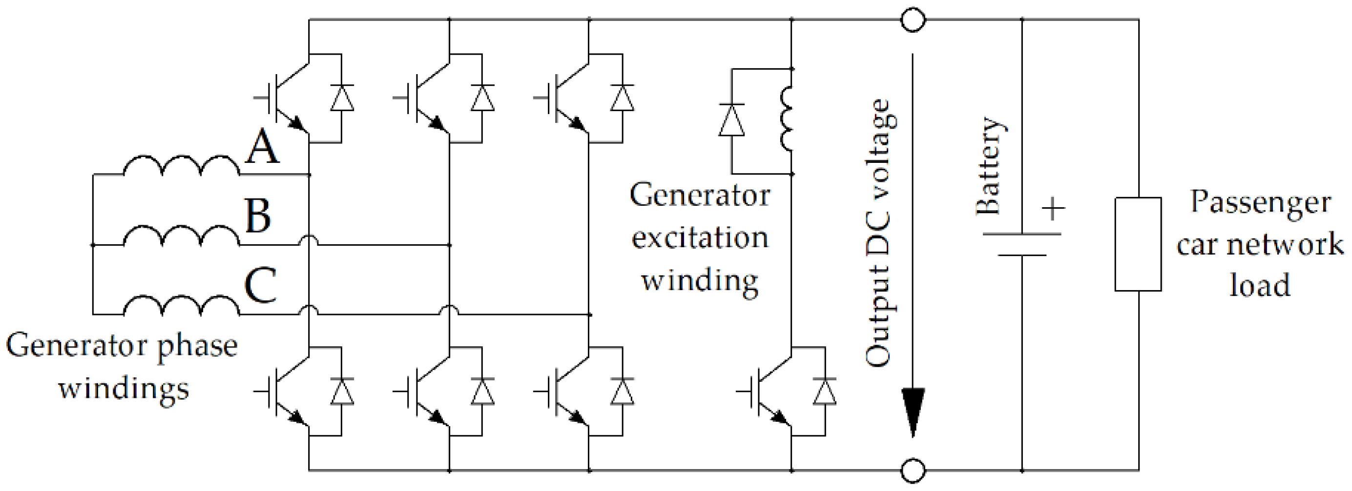
Figure 3.
Excitation winding flux path through the stator housing, the SRCSs, and the rotor sleeve.

Figure 4.
Computational domain.
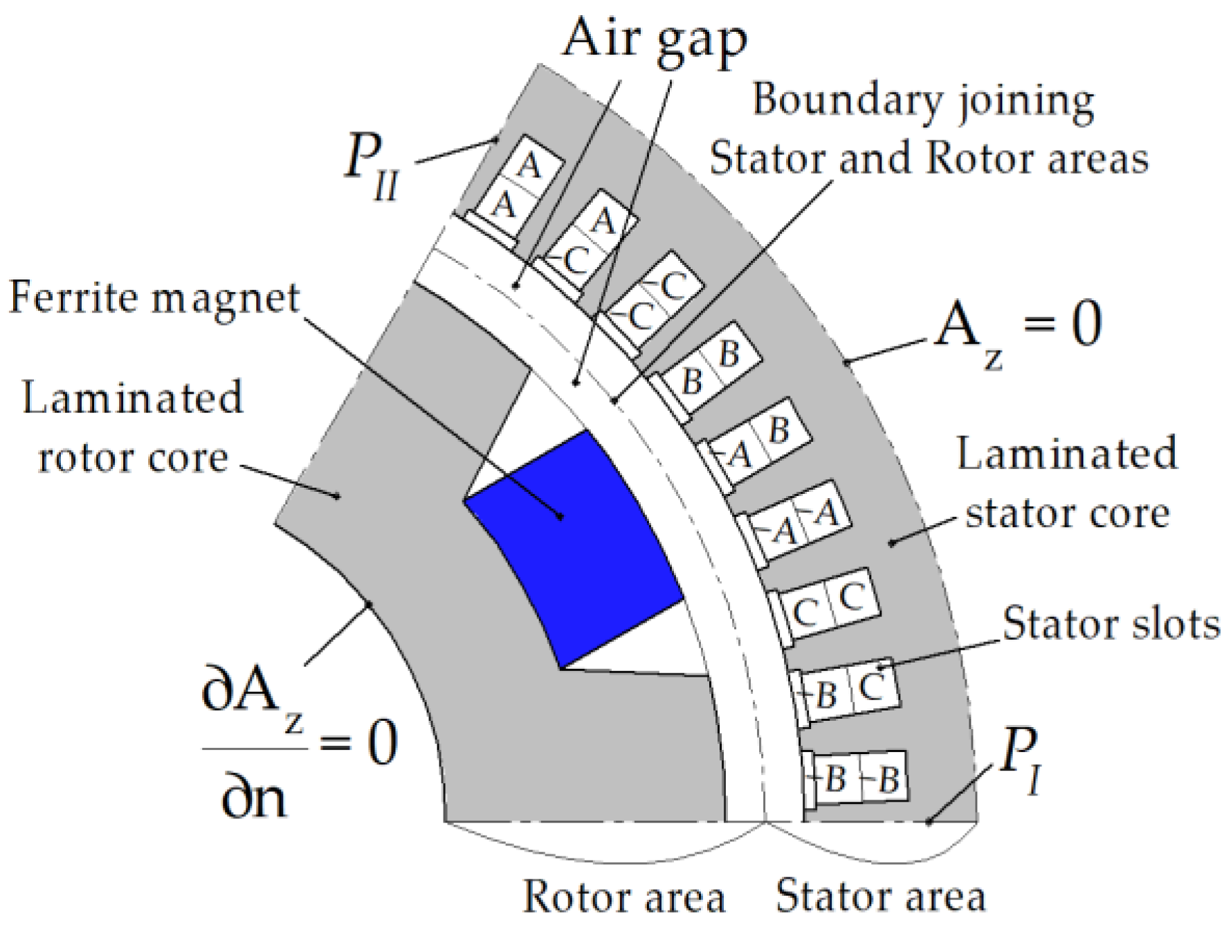
Figure 5.
The required torque and mechanical power of the generator as a function of speed.
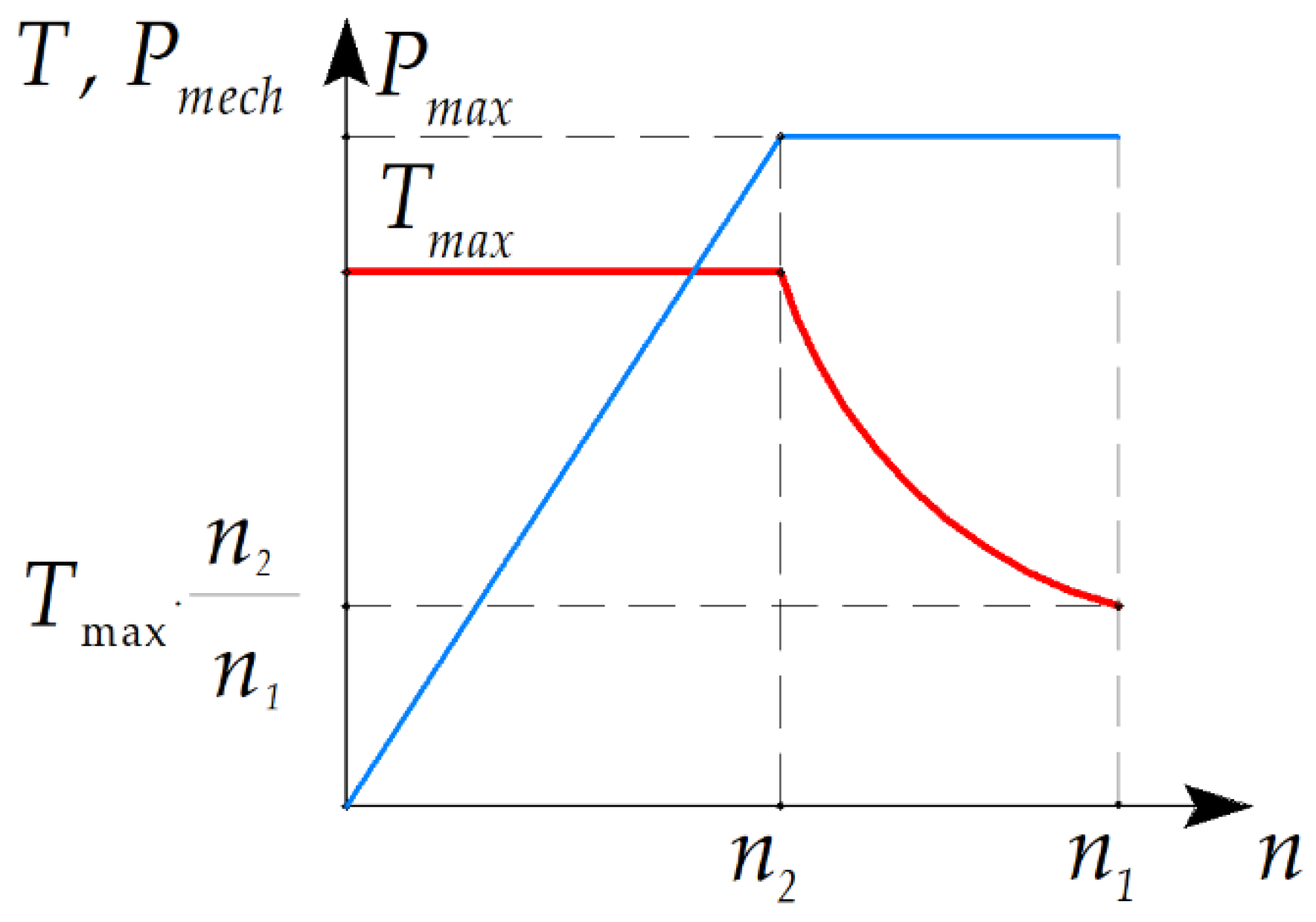
Figure 6.
Parameters of the SHG geometry. (a) Stator core parameters; (b) Rotor core parameters; (c) Armature winding parameters; (d) Parameters in the axial plane.
Figure 6.
Parameters of the SHG geometry. (a) Stator core parameters; (b) Rotor core parameters; (c) Armature winding parameters; (d) Parameters in the axial plane.
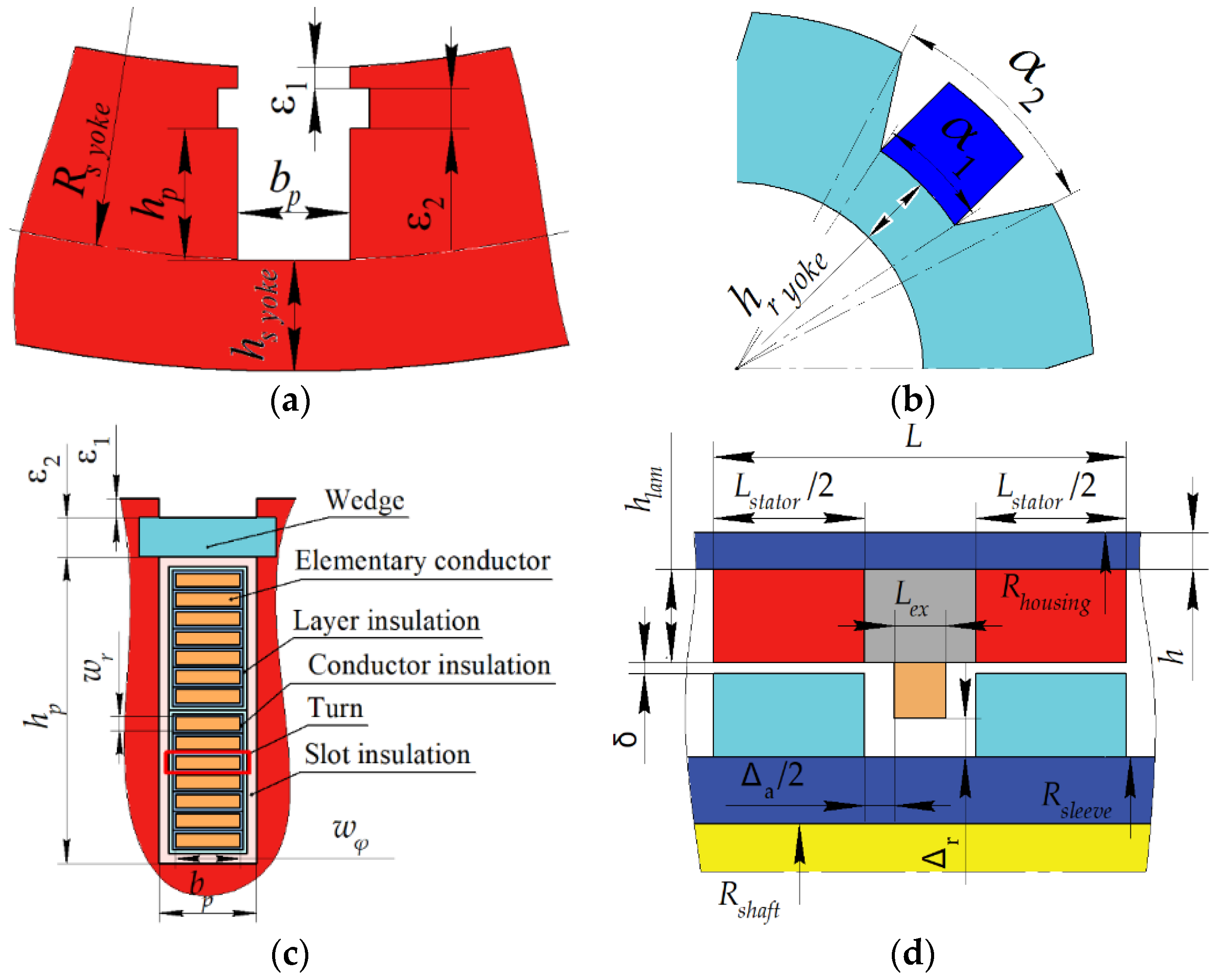
Figure 7.
Order of the SHM performance calculation during one step of the optimization. The objective function is defined by Equation (6). The input parameters are shown in Table 2.
Figure 7.
Order of the SHM performance calculation during one step of the optimization. The objective function is defined by Equation (6). The input parameters are shown in Table 2.
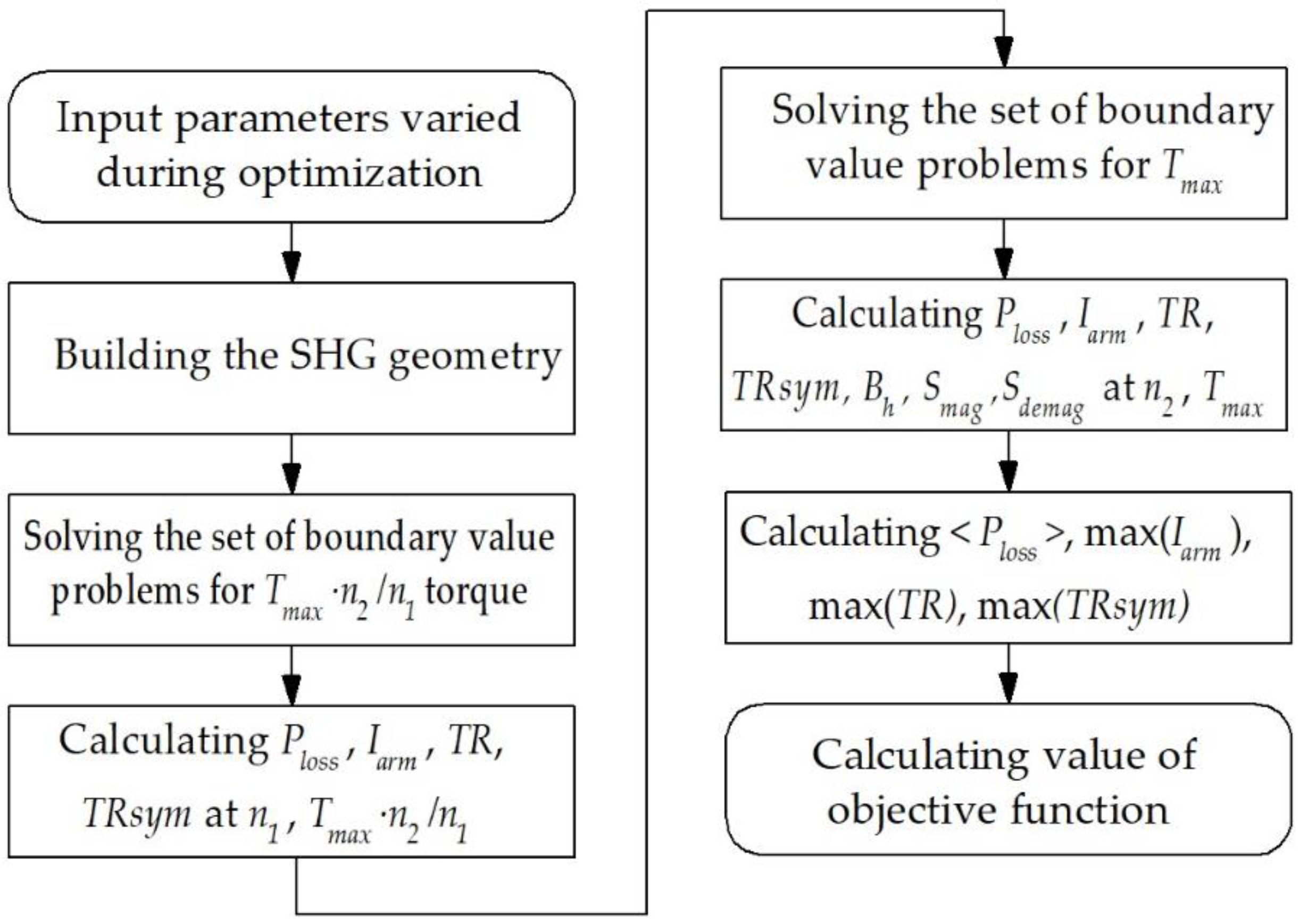
Figure 8.
Progress of the objective function (6) during optimization.

Figure 9.
Change of the generator parameters during optimization: (a) Average losses; (b) Maximum magnitude of the armature winding current.
Figure 9.
Change of the generator parameters during optimization: (a) Average losses; (b) Maximum magnitude of the armature winding current.
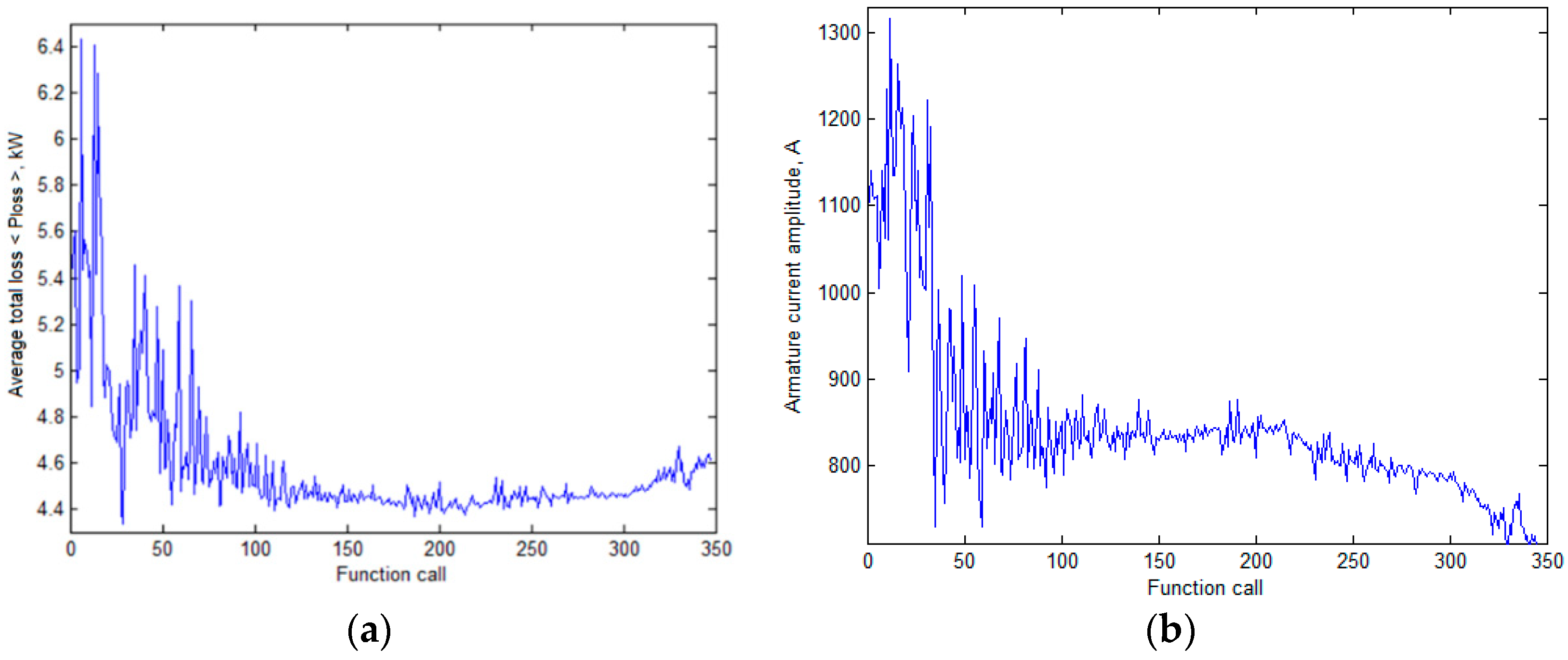
Figure 10.
Change of the generator parameters during optimization: (a) Nonsymmetrized torque ripple; (b) Symmetrized (output) torque ripple.
Figure 10.
Change of the generator parameters during optimization: (a) Nonsymmetrized torque ripple; (b) Symmetrized (output) torque ripple.
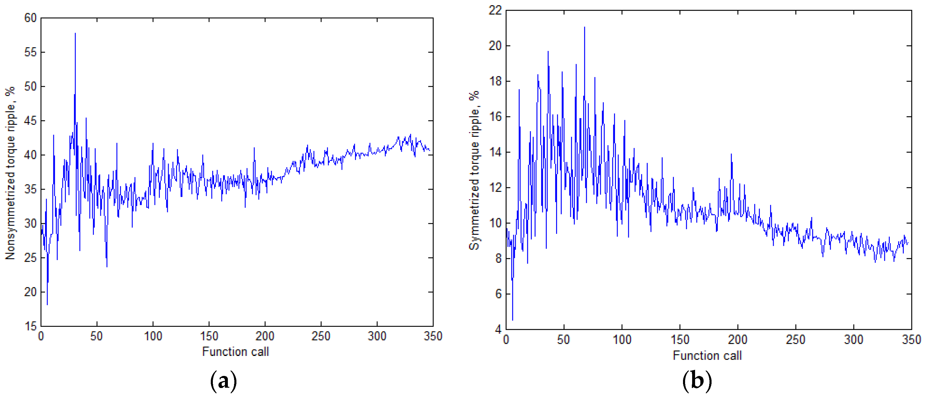
Figure 11.
The torque ripple of the individual SRSC and the symmetrized (output) torque ripple after optimization: (a) at 3450 rpm; (b) at 750 rpm.
Figure 11.
The torque ripple of the individual SRSC and the symmetrized (output) torque ripple after optimization: (a) at 3450 rpm; (b) at 750 rpm.

Figure 12.
Pole-sector geometry of the generator for the initial design. White color shows areas with flux density more than 2 T: (a) Maximum speed; (b) Maximum torque.
Figure 12.
Pole-sector geometry of the generator for the initial design. White color shows areas with flux density more than 2 T: (a) Maximum speed; (b) Maximum torque.
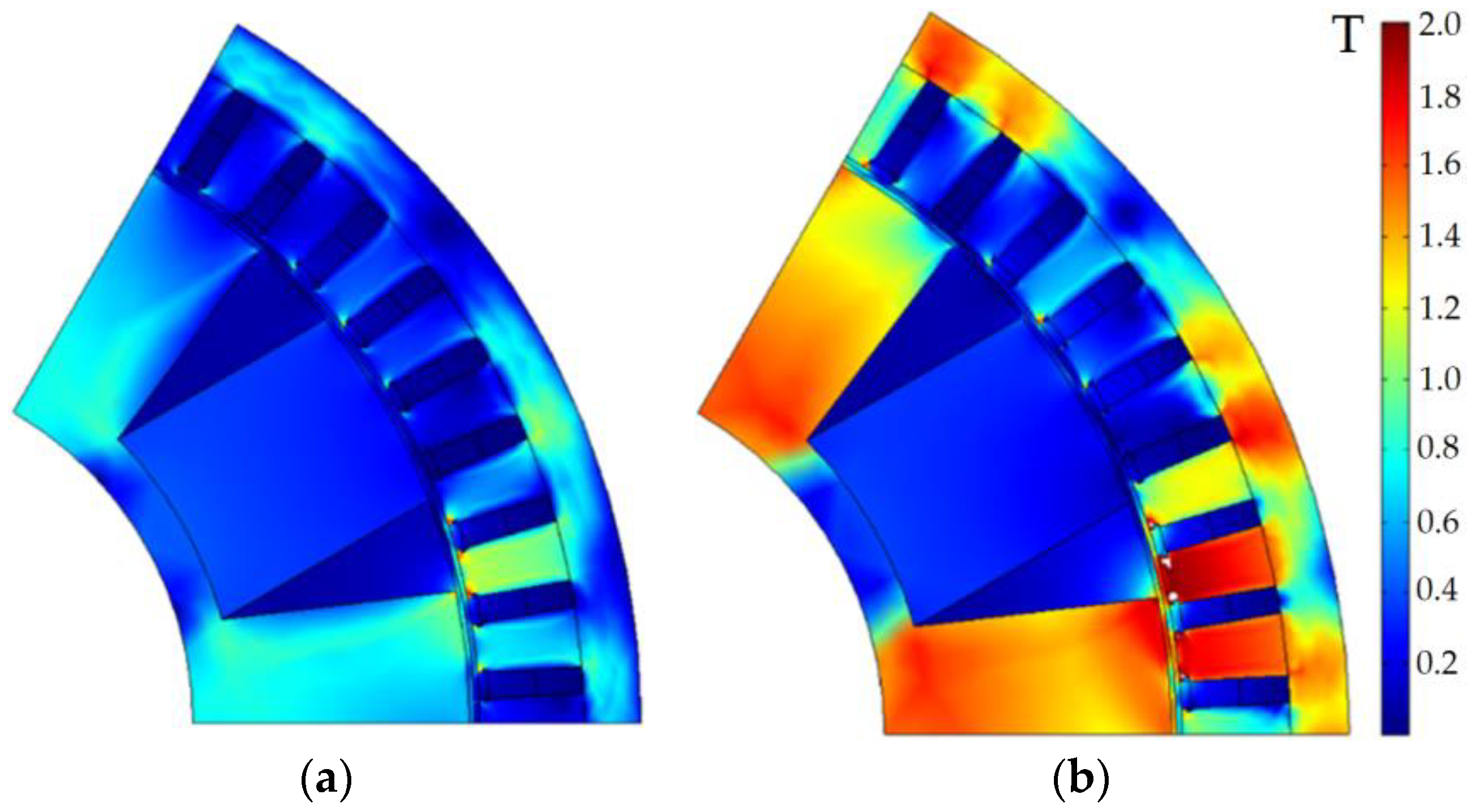
Figure 13.
Pole-sector geometry of the generator for the optimized design. White color shows areas with flux density more than 2 T: (a) Maximum speed; (b) Maximum torque.
Figure 13.
Pole-sector geometry of the generator for the optimized design. White color shows areas with flux density more than 2 T: (a) Maximum speed; (b) Maximum torque.
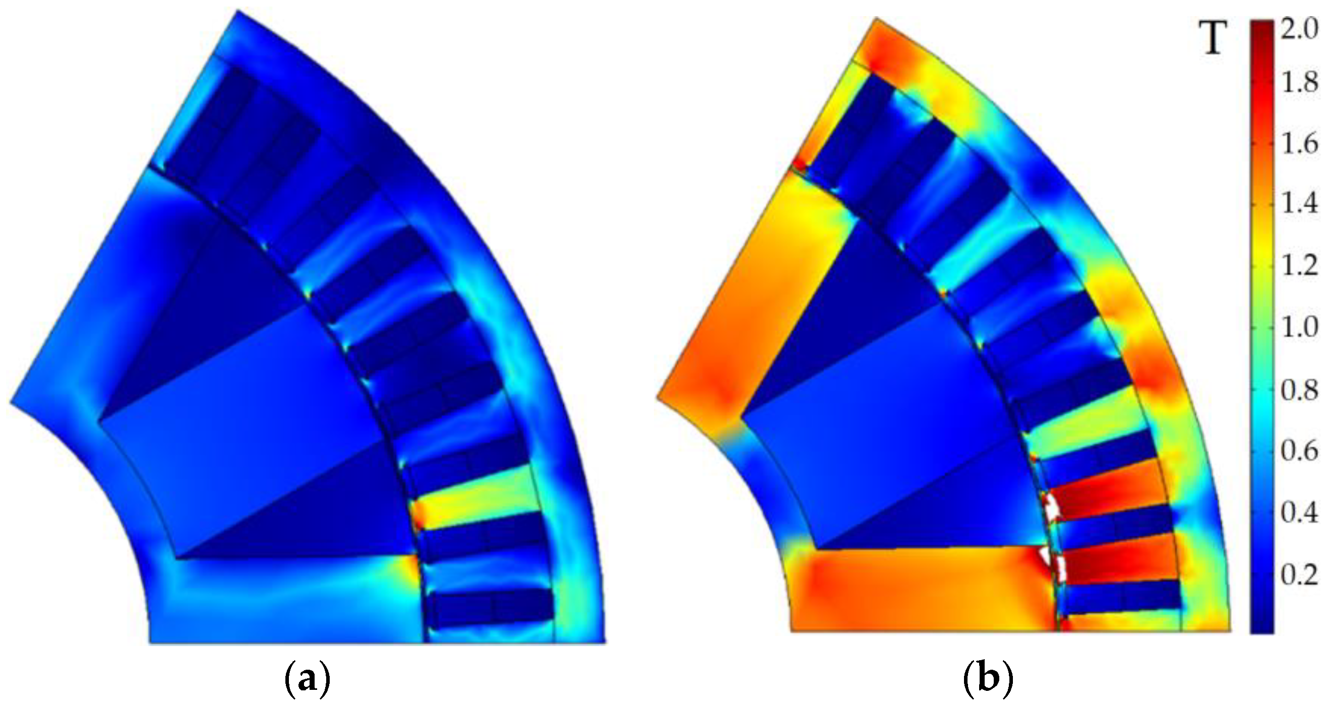
Figure 14.
Field of the demagnetizing force (kOe) acting on the permanent magnet of the rotor at the maximum torque (at 750 rpm): (a) Before optimization, minimum value is −3.0 kOe; (b) After optimization, minimum value is −2.9 kOe.
Figure 14.
Field of the demagnetizing force (kOe) acting on the permanent magnet of the rotor at the maximum torque (at 750 rpm): (a) Before optimization, minimum value is −3.0 kOe; (b) After optimization, minimum value is −2.9 kOe.


Table 1.
Main unchangeable parameters of the generator.
| Characteristics | Values |
|---|---|
| Length of all laminated stacks plus the axial clearances between them for installing excitation coils L, mm | 150 |
| Outer diameter of the stator housing, mm | 370 |
| Axial clearance between excitation coils and a rotor stack Δa, mm | 15 |
| Radial clearance between excitation coils and the rotor sleeve Δr, mm | 12 |
| Diameter of the rotor shaft, mm | 40 |
| Back iron width of stator lamination Hstator yoke, mm | 12 |
| Back iron width of rotor lamination Hrotor yoke, mm | 9 |
| Thickness of the stator wedge, ε2, mm | 1 |
| Stator tooth tip height ε1, mm | 1 |
| Current angle at 750 rpm, electrical radian | 0.1 |
| Grade of electrical steel | 2412 |
| Thickness of electrical steel, mm | 0.35 |
Table 2.
Initial and optimized vectors of the variable optimization parameters.
| Characteristics | Initial Design, x0 | Optimized Design, x |
|---|---|---|
| Housing thickness h, mm | 15 | 11.07 |
| Total stator stacks length Lstator, mm | 130 | 128.3 |
| Stator slot depth hp, mm | 20 | 27.9 |
| Stator slot width bp, mm | 5 | 6.37 |
| Airgap width δ, mm | 2 | 0.91 |
| Rotor slot thickness, α1 | 0.5∙tz * | 0.481∙tz * |
| Rotor slot thickness, α2 | 0.6∙tz * | 0.689∙tz * |
| Angle of field weakening at 3450 rpm, electrical radian | 0.6 | 0.93 |
| Current ratio ** @ 750 rpm | 8 | 14.54 |
| Current ratio ** @ 3450 rpm | 8 | 9.76 |
Notes: * tz = 360/6 = 60° (mechanical) is the rotor tooth pitch; ** the current ratio is the ratio between the current in a layer of the armature winding and the excitation current.
Table 3.
Generator characteristics before and after optimization.
| Characteristics | Initial Design | Optimized Design | ||
|---|---|---|---|---|
| Loading case, i | 1 | 2 | 1 | 2 |
| Rotational speed n, rpm | 3450 | 750 | 3450 | 750 |
| Armature phase current amplitude Iarm, A | 408 | 1035 | 375 | 700 |
| Efficiency, % * | 94.5 | 78.0 | 92.7 | 84.4 |
| Mechanical power on the generator shaft Pmech, kW | 40 | 40 | 40 | 40 |
| Shaft torque, N∙m | 111 | 510 | 111 | 510 |
| Output electrical power P1, kW | 37.97 | 32.36 | 37.22 | 34.90 |
| Armature DC copper loss Parm DC, kW | 1.12 | 7.21 | 1.29 | 4.51 |
| Armature eddy-current copper loss Parm AC, W | 123 | 46 | 402 | 157 |
| Stator laminated steel loss Piron st, W | 756 | 379 | 960 | 411 |
| Rotor laminated steel loss Piron rt, W | 33 | 9 | 121 | 24 |
| Excitation copper loss Pex, W | 187 | 1170 | 151 | 1123 |
| Total loss Ploss, kW ** | 2.22 | 8.81 | 2.93 | 6.22 |
| Average losses <Ploss>, kW | 5.51 | 4.58 | ||
| Turns number in the armature slot | 4.41 | 6.82 | ||
| Required rectifier power, kW | 104.0 | 70.3 | ||
| Power factor | 0.926 | 0.804 | 0.989 | 0.854 |
| Line-to-line voltage amplitude Varm, V | 116.0 | 44.9 | 116.0 | 67.4 |
| Nonsymmetrized torque ripple, % | 35 | 28 | 56 | 41 |
| Symmetrized torque ripple, % | 9.8 | 4.3 | 8.6 | 4.5 |
| Flux density in the non-laminated parts of the magnetic core, T | 0.4 | 1.3 | 0.1 | 1.5 |
Notes: * the generator efficiency was calculated as η = (P1 − Pex)/Pmech, where P1 is the active power in armature winding; Pex is the losses in the excitation winding; Pmech is the input (mechanical) power. The bearing loss and the loss due to air friction are not considered when calculating the efficiency; ** The total loss is calculated as the sum of the following Ploss = Parm DC + Parm AC + Piron st + Piron rt + Pex.
Table 4.
Characteristics of generators without magnets and with ferrite magnets.
| Characteristics | SHG without Magnets | SHG with Ferrite Magnets | ||
|---|---|---|---|---|
| Loading case, i | 1 | 2 | 1 | 2 |
| Rotational speed n, rpm | 3450 | 750 | 3450 | 750 |
| Armature phase current amplitude Iarm, A | 369.5 | 676.2 | 375 | 700 |
| Efficiency, % | 90.4 | 79.8 | 92.7 | 84.4 |
| Mechanical power on the generator shaft Pmech, kW | 40 | 40 | 40 | 40 |
| Shaft torque, N∙m | 111 | 510 | 111 | 510 |
| Output electrical power P1, kW | 36.58 | 33.12 | 37.22 | 34.90 |
| Armature DC copper loss Parm DC, kW | 1.90 | 6.37 | 1.29 | 4.51 |
| Armature eddy-current copper loss Parm AC, W | 417 | 131 | 402 | 157 |
| Stator laminated steel loss Piron st, W | 961 | 403 | 960 | 411 |
| Rotor laminated steel Piron rt, W | 192 | 26 | 121 | 24 |
| Excitation copper loss Pex, W | 368 | 1169 | 151 | 1123 |
| Total loss Ploss, kW | 3.84 | 8.10 | 2.93 | 6.22 |
| Average losses | 5.97 | 4.58 | ||
| Turns number in the armature slot | 7.75 | 6.82 | ||
| Required rectifier power, kW | 67.9 | 70.3 | ||
| Power factor | 1 | 0.747 | 0.989 | 0.854 |
| Line-to-line voltage amplitude Va, V | 116.0 | 75.3 | 116.0 | 67.4 |
| Nonsymmetrized torque ripple, % | 97.8 | 47.0 | 56 | 41 |
| Symmetrized torque ripple, % | 11.3 | 4.5 | 8.6 | 4.5 |
| Flux density in the rotor sleeve and in the stator housing, T | 0.84 | 1.60 | 0.1 | 1.5 |
Table 5.
Comparison of the cost and geometric characteristics of the considered configurations.
| Characteristics | SHG without Magnets | SHG with Ferrite Magnets |
|---|---|---|
| Stator laminated steel weight, kg | 34.2 | 28.0 |
| Rotor laminated steel weight, kg | 15.6 | 17.1 |
| Copper weight of armature winding, kg | 17.8 | 14.7 |
| Copper weight of excitation winding, kg | 2.44 | 2.62 |
| Weight of ferrite magnets, kg | - | 7.88 |
| Weight of structural steel of the rotor sleeve and stator housing, kg | 53.2 | 29.2 |
| Total weight of the active materials and the structural steel, kg | 123.24 | 99.5 |
| Stator laminated steel cost, USD | 34.2 | 28.0 |
| Rotor laminated steel cost, USD | 15.6 | 17.1 |
| Copper cost of armature winding, USD | 124.6 | 102.9 |
| Copper cost of excitation winding, USD | 17.1 | 18.3 |
| Cost of ferrite magnets, USD | - | 145.5 |
| Cost of the structural steel, USD | 53.2 | 29.2 |
| The total cost of the active materials (permanent magnets, copper, electrical steel) and low carbon steel of the stator housing of the rotor sleeve, USD * | 244.7 | 341.0 |
| Length of all stacks of the stator laminated steel, mm | 152.7 | 128.3 |
| Length of all laminated stacks plus the axial clearances between them for installing excitation coils, mm | 180 | 150 |
| Laminated stator external diameter, mm | 370 | 370 |
| Air gap, mm | 0.88 | 0.91 |
* Note: when calculating the cost of materials, it is assumed that the price of copper is $7 per kilogram; the price of electrical steel and the price of the structural steel are $1 per kilogram; the price of ferrite magnets of Y30H-2 grade is $18.46 per kilogram [38].
Disclaimer/Publisher’s Note: The statements, opinions and data contained in all publications are solely those of the individual author(s) and contributor(s) and not of MDPI and/or the editor(s). MDPI and/or the editor(s) disclaim responsibility for any injury to people or property resulting from any ideas, methods, instructions or products referred to in the content. |
© 2023 by the authors. Licensee MDPI, Basel, Switzerland. This article is an open access article distributed under the terms and conditions of the Creative Commons Attribution (CC BY) license (https://creativecommons.org/licenses/by/4.0/).
Share and Cite
MDPI and ACS Style
Prakht, V.; Dmitrievskii, V.; Kazakbaev, V. Analysis of Performance Improvement of Passenger Car Synchronous Homopolar Generator with the Addition of Ferrite Magnets. Appl. Sci. 2023, 13, 3990. https://doi.org/10.3390/app13063990
AMA Style
Prakht V, Dmitrievskii V, Kazakbaev V. Analysis of Performance Improvement of Passenger Car Synchronous Homopolar Generator with the Addition of Ferrite Magnets. Applied Sciences. 2023; 13(6):3990. https://doi.org/10.3390/app13063990
Chicago/Turabian StylePrakht, Vladimir, Vladimir Dmitrievskii, and Vadim Kazakbaev. 2023. "Analysis of Performance Improvement of Passenger Car Synchronous Homopolar Generator with the Addition of Ferrite Magnets" Applied Sciences 13, no. 6: 3990. https://doi.org/10.3390/app13063990
Note that from the first issue of 2016, this journal uses article numbers instead of page numbers. See further details here.