Abstract
Semantic segmentation of underground mine roads is very important to efficiently obtain road information from images. The boundary of underground mine roads is not obvious, the environment is complex, and road identification is difficult. In order to effectively realize the accurate identification of underground mine roads, a network identification model using a deep learning technique is proposed. Choosing BiSeNet as the basic framework, adopting a unified attention fusion module, and using channel and spatial attention to enrich the fusion feature representation can effectively obtain feature information and reduce the loss of feature information. In addition, the lightweight network STDC is integrated into the backbone network to reduce computational complexity. Finally, experiments were carried out on underground mine roads. The experimental results show that the mean intersection over union and pixel accuracy of the proposed method reached 89.34% and 98.34%, respectively, and the recognition speed reached 23 f/s when identifying underground mine roads. In this study, the underground mine road recognition model trained by deep learning technology can solve the problem of underground mine road recognition with high accuracy.
1. Introduction
Underground mining is a relatively special scene for autonomous landing applications. On the one hand, there are often obstacles such as gravel and water in mine roads that affect safe driving, and the lack of light in mine roads leads to blurred details of underground mine road images, low contrast, and difficulty in identifying features, and transportation accidents occur from time to time. On the other hand, due to the harsh working environment of the mine, safety accidents and frequent occupational diseases, it is very difficult to recruit mine car drivers, and only some older mine car drivers are still holding on. Although the treatment level of mine car drivers is constantly improving, younger drivers are rarely willing to engage in this industry. Therefore, it is an inevitable trend for mine transportation to develop unmanned and intelligent operation [1].
With the rapid development of deep learning, road detection technology using deep learning has gradually become a hot research field, and many achievements have been made in the field of road recognition [2,3,4,5,6,7]. In the identification of structured roads, structured roads have clear and standard lane lines, clear road boundaries, and are relatively easy to identify, so road areas can be identified by detecting lane lines. Many researchers have carried out a lot of work using semantic segmentation to identify lane lines [8,9,10,11,12,13]. For unstructured roads, such as rural roads, underground mine roads, etc., although there is no standardized lane line, many researchers have offered their solutions. Zhang et al. established a semantic segmentation network model based on unstructured road features [14] and the segmentation accuracy was significantly improved, but the real-time performance was poor and it could not be truly applied to actual engineering projects. Aiming at the problems of poorly defined road edges and the distant road segmentation effect, Gong et al. improved the network feature extraction capability by integrating the attention mechanism, and adopted a lightweight feature extraction network to greatly reduce the amount of model parameters under the premise of ensuring the recognition accuracy [15]. However, its accuracy and robustness are still poor.
The mining area is a relatively special scene for the application of autonomous driving. The poor conditions of the mine are mainly manifested in poor road conditions, more gravel and more dust in the mining area. Many mines are mined along the mountain; the road construction is difficult and the service life is short. Therefore, the road surface of the mining area is mostly paved with gravel, and the road conditions are complex, which is more likely to damage vehicle parts and shorten vehicle life. In addition, there is much dust in the mining area, and the dust particles are large. The sensing equipment is easily covered by dust and this affects the environmental perception ability of the unmanned mine car. In addition to the impact of the complex road environment on the unmanned mine car, there are also some problems in the versatility, reliability and safety of the technology. First, in different mining areas, the mine car will fail due to some unique situations; the electromagnetic characteristics of metal ore will affect the performance of millimeter wave radar, and the temperature of alpine mining areas will affect the stability of electrical and electronic components. Second, the environment of the mining area is complex and harsh. Dust, flying stones, and so on pose a great threat to the perception layer of the unmanned mine car. The probability of the perception equipment being hit in a mining area with many rockfalls greatly affects its safety. In view of the challenges of mine roads, some researchers have also carried out extensive work [16,17,18,19,20,21,22]. Wei Xing et al. improved the pyramid attention module of the original bilateral network and the channel attention fusion module [23,24] for the detection of underground coal mine tracks, which improved the detection accuracy. Zhou and others realized the real-time identification of the central area, left safety area and right safety area of the underground track by improving the BiSeNet network [25]. However, due to the lack of information exchange between parallel branches, it cannot achieve good results in the road identification of underground mine slopes, and it mainly studies the straight roads of mines, and does not consider special roads features such as bends and forks. Shi et al. studied a method for rapid detection of rockfall using laser radar, which can reduce the wear of rockfall on mine car tires and reduce mining costs [26]. Yuan et al. derived the vehicle position and attitude information using ultra-wideband positioning technology to provide support for unmanned positioning technology in underground coal mines [27]. Wang et al. improved the RRT * algorithm to solve the path planning problem of underground unmanned vehicles using articulated structures and drift environmental conditions. This provides a new method for underground mine vehicle path planning [28]. Gin et al. proposes a real-time traffic identification method based on a low-power embedded device, NVIDIA Jetson AGX Xavier [29]. This low-power device embedded into the unmanned mine car can judge the road conditions of the underground mine road in time and ensure the safe driving of the unmanned mine car.
In summary, there are many problems in the application of driverless technology to mine roads, such as the complex environment of mine roads, the fuzzy and discontinuous road boundaries, the uneven road surfaces, and the flying sand. It can be concluded that the special challenges of underground mine roads are as follows:
- Underground mine roads have a certain slope, and misidentification may occur when identifying roads through images.
- The boundary of underground mine road is not obvious and the light is not sufficient, which makes it difficult to identify the exercise area of underground mine road.
To address the aforementioned challenging issues in the mine environment, this paper studies an underground mine road recognition method using a camera to collect images for real-time semantic segmentation of underground mine slopes, effectively segmenting the drivable area in the mine slope scene, and realizing real-time and accurate recognition of underground mine slopes. The main contributions of this study are as follows:
- Aiming at the characteristics of the underground mine slope road environment, we improved the BiSeNet semantic segmentation network.
- A dataset of underground mine roads is constructed, and the dataset is augmented by data augmentation.
- The model is verified by experiments and compared with other classical models.
2. Materials and Methods
The detection process of the drivable area of the underground mine road image is shown in Figure 1. It mainly includes two stages of training and application. In the training stage, the mine road image is collected by the camera mounted in front of the mine car, and the dataset is expanded by the data enhancement method, and the driving area of the underground mine road is marked. The underground mine road image dataset is put into the semantic segmentation network for training. When the loss value converges, the model is trained. In the application stage, the driving area of the underground mine road can be detected by inputting the image of the underground mine road into the trained model.
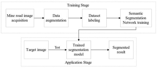
Figure 1.
Underground mine road image segmentation flow chart.
BiSeNet is used as the basic network model for semantic segmentation of underground mine slopes. The BiSeNet network designs two branch networks, namely Spatial Path and Context Path (CP). Aiming at the problem of spatial information loss in semantic segmentation, the spatial path solves the problem of spatial information loss by acquiring more low-level features, thus encoding rich spatial information, while the context path provides a larger receptive field.
The main structure of the BiSeNet network is shown in Figure 2. There are 3 layers in the spatial path. The size of the convolution kernel of the first layer is 7 × 7, and the size of the convolution kernel of the last two layers is the same as 3 × 3. Each layer has to undergo convolution with a stride of 2. Using convolution (CONV), batch normalization (BN) and a ReLU nonlinear activation operation, the image size output by this path is 1/8 of the original image, and the context path provides enough experience and semantic information to the network. The attention refinement module (ARM), based on the global average pooling to obtain the global context, guides feature learning by calculating the attention vector, and refines the output features of the context path. Obtaining global contextual information through an attention optimization module can improve image segmentation accuracy. The model designs a feature fusion module (FFM) to fuse spatial features and contextual information to improves the feature extraction capability. The fusion layer uses bilinear interpolation to upsample the feature map size extracted by the context path to the same size as the feature map obtained by the spatial path, and then these features are fused through the feature fusion layer. This module pools connected features into feature vectors and computes weight vectors, which are used to re-weight the features to output features that combine spatial and contextual paths.
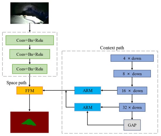
Figure 2.
BiSeNet network.
The underground mine road environment is complex, and has problems such as uneven roads, obstacles, and insufficient illumination. The mainstream deep learning model, although high in accuracy, cannot run complex deep learning network models due to the limited computing power of the mine car’s on-board computer. Therefore, in the face of the complex mine road environment, it is difficult to meet the real-time demand. BiSeNet’s semantic segmentation algorithm uses a lightweight backbone specially designed for classification tasks, and cannot give full play to the performance of the BiSeNet algorithm in the field of semantic segmentation. Due to the complex environment of underground mines and poor light conditions, BiSeNet using the classification backbone network cannot accurately identify roads. For the situation of underground mine roads, the network needs to be improved. STDC is a real-time semantic segmentation network proposed by Meituan, which gradually reduces the dimension of feature maps and uses aggregated information to represent images [30]. On BiSeNet, this study replaced the backbone network with STDC. By changing the backbone network, the real-time performance of the network model is improved, and can also achieve better real-time performance within the complex and changeable environment of the underground mine road. The improved BiSeNet mainly consists of a spatial path and a contextual path. First of all, the lightweight network short-term dense concatenate is used as the backbone network of the encoder in the space path, and the original three sets of convolutional layers are replaced. The replaced backbone is composed of STDC modules. The number of deep feature channels is small, and the number of shallow feature channels is large. The STDC module uses skip connections to enrich features, so that the lower layers have enough channels to encode more detailed information with smaller receptive fields, and the higher layers with larger receptive fields strengthen the expression of high-level information. The backbone network composed of STDC modules can reduce the calculation amount of the model network and improve the calculation speed. A unified attention fusion module (UAFM) is added to the context path, which enriches the feature representation. The UAFM improves the detection level of underground mine slopes through channel and spatial attention. The semantic segmentation network model of the improved BiSeNet is shown in Figure 3; the red box of the space path is the lightweight backbone network STDC, and the red box of the context path is the UAFM.
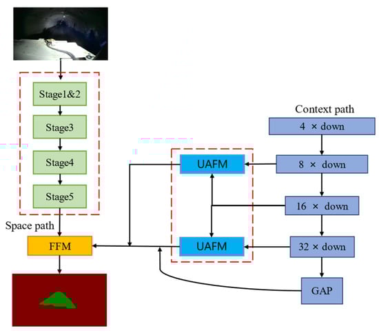
Figure 3.
Improved BiSeNet network.
2.1. STDC Backbone Network
2.1.1. STDC Module
Figure 4 shows the structure of the STDC module. Each module is divided into several blocks, and ConvXi is used to represent the operation of the i block. The output of block i can be calculated by the following formula:
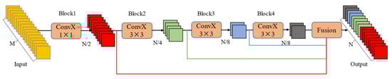
Figure 4.
STDC module.
The input of i module is xi−1, and the output is xi. ConvX consists of three parts: convolution layer, normalization layer and ReLU activation layer. Ki is the size of the convolution kernel. The kernel size of the first ConvX of this module is 1 × 1, and the remaining ConvX kernels are 3 × 3. Assuming that N is the number of channels output from the STDC module, the number of filters in the ith convolutional layer can be calculated from N/2i.
2.1.2. STDC Module Receptive Field
Scalable receptive field and multi-scale information is the focus of image semantic segmentation. The lower layers need enough channels to encode more detailed information with smaller receptive fields, while the higher layers with larger receptive fields pay more attention to the expression of high-level information, and setting the same channel as a lower layer may lead to information redundancy. The x1 to xn features are spliced together as the output through the skip path, thereby enriching the feature information. Before cascading, the average pooling of 3 × 3 is used to downsample the response maps of different blocks in the STDC module to the same size. The output results are as follows:
where Xoutput represents the STDC module output, F represents the fusion operation, and X1, X2, Xn are the feature maps of all n blocks.
2.1.3. STDC Network
STDCMNet (short term dense concatenate network) is a lightweight semantic segmentation network proposed by Meituan, which is an upgrade and improvement based on BiSeNet. STDCNet has two main contributions. On the one hand, it improves the backbone of the backbone network and changes the structure of the dense concatenate module. In the same STDC module, the number of channels output by each ConvX gradually decreases with the increase in the receptive field, and finally concatenate together, so it contains more feature scale information. On the other hand, it is a multi-branch low-level detail information assisted training structure. The detail information guidance structure is only used during training. After the network training is completed, it can be directly discarded. This method can reduce the amount of calculation during reasoning compared to the previous BiSeNnet. The network structure organized from the perspective of network output is shown in Figure 5.

Figure 5.
STDC Network.
As shown in Figure 6, excluding the input and output layers, the STDC network consists of 6 stages. Stages 1 to 5 downsample the input spatial resolution with a step size of 2, and the final feature map size is 1/32 of the input image. Stage 6 outputs the prediction logic using ConvX, a global average pooling layer, and two fully connected layers. Stages 1 and 2 use only one convolutional block to extract features, thus increasing efficiency.
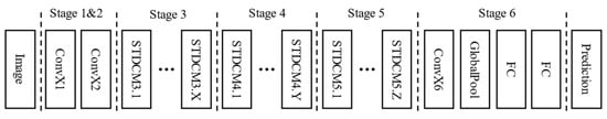
Figure 6.
STDC network structure.
2.2. Unified Attention Fusion Module (UAFM)
Underground mine roads are the most irregular of unstructured roads, and are affected by light, water, potholes, etc., making it difficult to achieve accurate identification of underground mine roads. Aiming at the problem of low recognition accuracy of underground mine roads, this study uses a unified attention fusion module to enrich the fusion feature representation through spatial and channel attention fusion, thereby improving the recognition accuracy of the model. As shown in Figure 7, the UAFM utilizes an attention module to generate the weight α, and fuses the input features with α through Mul and Add operations. The input features are denoted as Fhigh and Flow. Fhigh is the output of the deep module, and Flow is the corresponding module of the encoder with the same number of channels.
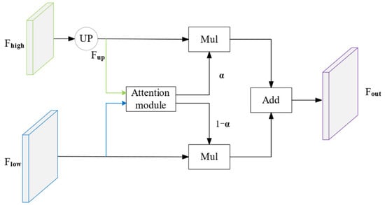
Figure 7.
Unified Attention Fusion Module.
The UAFM uses a bilinear interpolation operation to upsample Fhigh to the same size as Flow, and the upsampled feature is denoted as Fup. Then, the attention module takes Fup and Flow as input and generates the weight α. After obtaining the attention weights, Mul operations are performed on Fup and Flow, respectively. Finally, the UAFM performs the Add operation on the attention-weighted features and outputs the fusion features, calculated as follows:
The spatial attention module, shown in Figure 8, exploits the inter-spatial relationship to generate a weight that represents the importance of each pixel in the input feature.
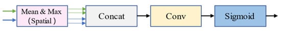
Figure 8.
Spatial Attention Module.
Given input features, Fup ∈ RC×H×W sum, 4 features are first generated by averaging and maximizing operations along the channel axis, where the dimension is R1×H×W. Then, these 4 features are concatenated onto one feature. For the concatenated features, convolution and sigmoid operations are applied to the output α ∈ R1×H×W. The calculation formula of the spatial attention module is as follows:
Figure 9 shows the channel attention module. The key to the channel attention module is to use the relationship between channels to generate a weight. For this weight, each channel of the input feature is important. The proposed channel attention module uses the average and max pooling to compress the spatial dimension of the input features.
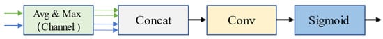
Figure 9.
Channel Attention Module.
This process generates 4 features using dimension RC×1×1. These 4 features are then concatenated along the channel axis, and convolution and sigmoid operations are performed to produce a weight α ∈ RC×1×1. The formula is expressed as follows:
3. Experiment and Results
3.1. Experimental Parameter Settings
The training process was carried out in the Windows + cuda10.1 system environment, the computer configuration is i5-10300H CPU, 16GB memory, and the graphics card is NVIDIA GTX1650ti 4G memory GPU. A neural network program was written using the Paddle2.2 framework. In this experiment, STDC was used as the backbone network, and mini-batch stochastic gradient descent was selected for training. In this paper, the “poly” strategy was used to adjust the learning rate, and the power was set to 0.9. Compared with the traditional strategy of updating the learning rate, the “poly” strategy has a more obvious effect on accelerating the network convergence. The experimental parameters are shown in Table 1.

Table 1.
Experimental parameter table.
3.2. Dataset Construction
The front vehicle condition camera installed on the mine car was used to collect video data, and obtain the image of the underground mine slope by extracting video frames. The data included curves, dust and sand effects, and road images under different lighting conditions. Images under different environmental conditions enhance the robustness of the network and improve the recognition ability of the network. the extracted image data were screened to remove image data that seriously affect network training, such as repetition and ambiguity. Due to the particularity of the underground mine environment, data collection is more difficult, the video data collected are limited, less image data are extracted, and the dataset required for neural network training is larger, so the method of data enhancement was used to increase the amount of data. Transformations such as horizontal mirroring, vertical flipping, vertical mirroring, brightness enhancement, and contrast enhancement were used during training. Figure 10 shows before and after transformation; the enhanced data can make up for the shortcomings of less data. The image resolution size was uniformly processed as 1280 × 720, and the data were divided randomly into training set and verification set according to the ratio of 8:2.
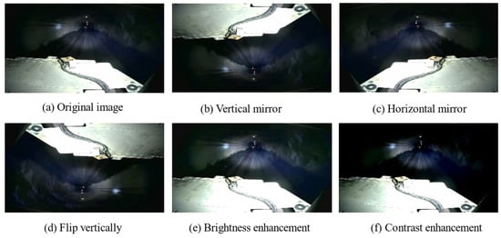
Figure 10.
Data augmentation.
3.3. Experimental Evaluation Index
In order to quantitatively analyze the segmentation effect of the algorithm, mean intersection over union (mIoU), pixel accuracy rate (PA—pixel accuracy), and Dice coefficient were used as the evaluation indicators of the road segmentation model. The indicators are defined as follows:
mIoU: the ratio of the intersection and union of the predicted value set and the real value set is calculated, the IoU on each category is calculated, and the mean value is taken to be the mIoU. The calculation method is as follows:
Among them, TP is the number of pixels that are correctly classified as foreground, TN is the number of pixels that are wrongly classified as foreground, FP is the number of pixels that are wrongly classified as background, and FN is the number of pixels that are correctly classified as background.
Pixel accuracy rate PA: refers to the proportion of the predicted correct pixel amount to the total pixel amount. The calculation method is as follows:
Dice similarity: Dice similarity is also known as F1 metric, which is determined by two parameters, precision and recall, and is used to calculate the similarity of two sets. When the Dice value is high, it means that the experimental method is more effective. The calculation method is as follows:
where R is the recall rate, which refers to the ratio of the number of pixels that are correctly predicted as foreground to the total number of pixels that are actually foreground; P is the precision, which refers to the number of pixels that are correctly predicted as foreground and the number of pixels that are predicted to be foreground ratio.
3.4. Model Training
Figure 11 shows the change curve of the loss value during the training of the network, and the mIoU change is shown in Figure 12. In the process of network training, as the number of iterations continues to increase, the loss value continues to decrease. When the number of iterations reaches 20,000, the loss value reaches a minimum of about 0.1179, and the mean intersection over union of the network reaches 89%. The model basically converges.
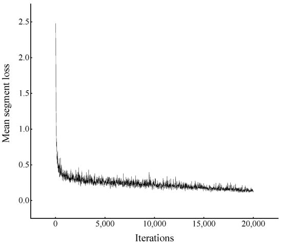
Figure 11.
Loss curve.
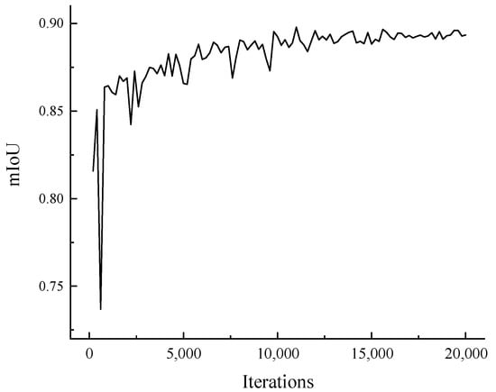
Figure 12.
Mean intersection over union curve.
4. Discussion
In addition to comparing the improved network with the network, this paper also selects the SegNet network with high segmentation accuracy and fast detection speed, and the small size of the ENet network is compared and verified with the network in this paper. The comparison results are shown in Table 2.
Table 2.
Comparison of evaluation indexes of different networks on underground mine slope dataset.
SegNet is a classic semantic segmentation network. In this experiment, mIoU reached 86.55%, and the accuracy rate is the second highest, reaching 97.81%. Its achievement lies in its encoder–decoder structure. The way the decoder performs upsampling directly uses the pooling index when performing the maximum pooling in the corresponding encoder stage to perform non-linear upsampling. However, the frames per second of SegNet is only 2 f/s, which is the slowest among the four networks. The mIoU of ENet reached 85.34%, and the pixel accuracy reached 97.53%, which is similar to that of SegNet. Because the ENet network is relatively light, its operating speed reached 13 f/s, which is much faster than that of SegNet, but it is still not sufficient for real-time purposes. The mIoU of BiSeNet is the lowest, only 74.83%, the Dice is also the lowest, only 83.22%, and the frame rate is only 7 f/s. Compared with SegNet and ENet, BiSeNet has almost no advantages.
It can be seen from the data in the table that the improved BiSeNet in this paper has obvious advantages in the mean intersection over union and pixel accuracy. The improved BiSeNet, due to the replacement of the backbone and the addition of a unified attention fusion module, mIoU and fps are 89.34% and 13 f/s, respectively, which have been greatly improved. Compared with the original BiSeNet, the mean intersection over union and pixel accuracy are improved by 19% and 3%. Compared with the previous network, the segmentation effect is the best, and can meet the real-time requirements. The frame rate of the network in this paper can reach 23 f/s, which basically meets the requirements of real-time recognition. The experimental results show that the improved network segmentation rate has been significantly improved, and compared with other networks, the accuracy is also higher, and it has a better segmentation effect.
In order to illustrate the effectiveness of replacing the backbone network and adding the UAFM module, we compared the performance of the network before and after the replacement on underground mine roads, as well as the performance after adding a unified attention fusion module, and the mIoU improvement after replacing the backbone network with STDC. After adding the UAFM on this basis, the mIoU increased by 2.08%. Table 3 shows the specific experimental results.
Table 3.
Comparison of the effect of replacing the backbone network and adding UAFM.
Figure 13 includes the following images: (a) shows the input color image; (b) shows the label; (c) shows the target for road recognition in underground mines; (d)~(g) show the results of different network models.
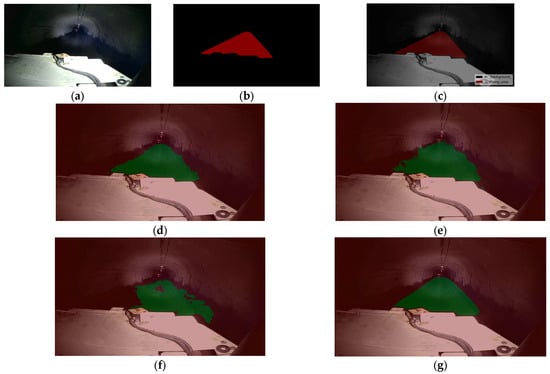
Figure 13.
Results comparison chart: (a) original image; (b) label; (c) target; (d) SegNet; (e) ENet; (f) BiSeNet; and (g) the network in this article.
The continuous identification of underground tunnels can explain the robustness of the model. Therefore, we conducted continuous identification experiments on underground mine tunnels. Figure 14 is a comparison chart of the mine road recognition results at different time points. It can be seen that the improved network has a better effect on identifying underground mine slope roads.
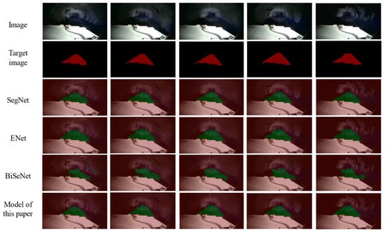
Figure 14.
Comparison chart at different time points.
The external environment also affects the recognition of underground mine roads, and the underground mine road environment is special, and there is wind and sand blowing from time to time, which has a certain impact on the camera. Moreover, there are more straight roads and fewer curves in underground mine roads. Therefore, in order to prove the robustness and advancement of the improved network, this paper takes the bends and wind and sand into account, and verifies it through comparative experiments. The experimental results are shown in Figure 15.
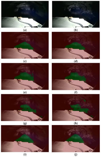
Figure 15.
Comparison of the recognition effects of curved roads and sandy roads: (a) bend; (b) wind and sand; (c) SegNet_1; (d) SegNet_2; (e) ENet_1; (f) ENet_2; (g) BiSeNet_1; (h) BiSeNet_2; (i) BiSNet_improved_1; and (j) BiSNet_improved_2.
5. Conclusions
Aiming at the semantic segmentation of underground mine roads, an improved network detection model BiSeNet using deep learning technique is proposed. It integrates the backbone network of the STDC model with the agreed attention fusion module UAFM, thereby enriching the feature representation and improving the learning ability of the network model. The improved BiSeNet mine road detection model is tested on the dataset constructed based on the underground mountain road image, and compared with other methods. The experimental results show that the improved BiSeNet network increases the mIoU and PA of the mine road to 89.34% and 98.34%, respectively, and the frame rate to 23 f/s. It provides a reliable reference for the environmental perception of unmanned mine trucks on underground mine roads.
Although the semantic segmentation network proposed in this paper can achieve better detection of mine road areas in the context of underground mines, this study only recognizes the road areas in the image, and does not take into account the interference factors such as road workers and rockfalls on the mountain, which will be studied and solved in our future work.
Author Contributions
Conceptualization, Z.T.; investigation, Z.T.; resources, Z.T.; data curation, Z.T.; writing—original draft preparation, W.Z.; writing—review and editing, X.Z.; visualization, W.Z.; supervision, X.Z.; project administration, X.Z. All authors have read and agreed to the published version of the manuscript.
Funding
This research was funded by the Key Laboratory Project of Shaanxi Province Department of Education (20JS063).
Institutional Review Board Statement
Not applicable.
Informed Consent Statement
Not applicable.
Data Availability Statement
Not applicable.
Conflicts of Interest
The authors declare no conflict of interest.
References
- Jung, D.; Choi, Y. Systematic Review of Machine Learning Applications in Mining: Exploration, Exploitation, and Reclamation. Minerals 2021, 11, 148. [Google Scholar] [CrossRef]
- Yoneda, K.; Suganuma, N.; Yanase, R.; Aldibaja, M. Automated driving recognition technologies for adverse weather conditions. IATSS Res. 2019, 43, 253–262. [Google Scholar] [CrossRef]
- Sim, H.; Do, T.D.; Lee, S.; Kim, Y.H.; Kim, S.C. Road environment recognition for automotive FMCW radar systems through convolutional neural network. IEEE Access 2020, 8, 141648–141656. [Google Scholar] [CrossRef]
- Yong, P.; Wang, N. RIIAnet: A Real-Time Segmentation Network Integrated with Multi-Type Features of Different Depths for Pavement Cracks. Appl. Sci. 2022, 12, 7066. [Google Scholar] [CrossRef]
- Firkat, E.; Zhang, J.; Wu, D.; Yang, M.; Zhu, J.; Hamdulla, A. ARDformer: Agroforestry Road Detection for Autonomous Driving Using Hierarchical Transformer. Sensors 2022, 22, 4696. [Google Scholar] [CrossRef]
- Yu, K.; Xu, C.; Ma, J.; Fang, B.; Ding, J.; Xu, X.; Bao, X.; Qiu, S. Automatic Matching of Multimodal Remote Sensing Images via Learned Unstructured Road Feature. Remote Sens. 2022, 14, 4595. [Google Scholar] [CrossRef]
- Kortli, Y.; Gabsi, S.; Voon, L.F.L.Y.; Jridi, M.; Merzougui, M.; Atri, M. Deep embedded hybrid CNN–LSTM network for lane detection on NVIDIA Jetson Xavier NX. Knowl.-Based Syst. 2022, 240, 107941. [Google Scholar] [CrossRef]
- Qin, Z.; Wang, H.; Li, X. Ultra Fast Structure-Aware Deep Lane Detection. In Computer Vision–ECCV 2020, Proceedings of the 16th European Conference, Glasgow, UK, 23–28 August 2020; Vedaldi, A., Bischof, H., Brox, T., Frahm, J.-M., Eds.; Springer: Cham, Switzerland, 2020. [Google Scholar]
- Yoo, S.; Lee, H.; Myeong, H. End-to-End Lane Marker Detection via Row-wise Classification. In Proceedings of the 2020 IEEE/CVF Conference on Computer Vision and Pattern Recognition Workshops (CVPRW), Seattle, WA, USA, 14–19 June 2020. [Google Scholar]
- Kim, J.; Park, C. End-to-end ego lane estimation based on Sequential Transfer Learning for self-driving cars. In Proceedings of the 2017 IEEE Conference on Computer Vision and Pattern Recognition Workshops (CVPRW), Honolulu, HI, USA, 21–26 July 2017. [Google Scholar]
- Neven, D.; Brabandere, B.D.; Georgoulis, S.; Proesmans, M.; Gool, L.V. Towards end-to-end lane detection: An instance segmentation approach. In Proceedings of the 2018 IEEE Intelligent Vehicles Symposium (IV), Suzhou, China, 26–30 June 2018. [Google Scholar]
- Bruls, T.; Maddern, W.; Morye, A.A.; Newman, P. Mark yourself: Road marking segmentation via weakly-supervised annotations from Multimodal Data. In Proceedings of the 2018 IEEE International Conference on Robotics and Automation (ICRA), Brisbane, QLD, Australia, 21–25 May 2018. [Google Scholar]
- Khan, M.A.-M.; Kee, S.-H.; Sikder, N.; Mamun, M.A.A.; Zohora, F.T.; Hasan, M.T.; Bairagi, A.K.; Nahid, A.-A. A Vision-based lane detection approach for autonomous vehicles using a convolutional neural network architecture. In Proceedings of the 2021 Joint 10th International Conference on Informatics, Electronics & Vision (ICIEV) and 2021 5th International Conference on Imaging, Vision & Pattern Recognition (icIVPR), Online, 16–19 August 2021. [Google Scholar]
- Zhang, K.H.; Ji, J. The semantic segmentation of driving regions on unstructured road based on segnet architecture. J. Chongqing Univ. 2020, 43, 79–87. [Google Scholar]
- Gong, Z.L.; Gu, Y.H. Unstructured road recognition based on attention mechanism and lightweight DeepLabv3+. Microelectron. Comput. 2022, 39, 26–33. [Google Scholar]
- Tang, J.; Lu, X.; Ai, Y.; Tian, B.; Chen, L. Road Detection for Autonomous Truck in Mine Environment. In Proceedings of the 2019 IEEE Intelligent Transportation Systems Conference (ITSC), Auckland, New Zealand, 27–30 October 2019; pp. 839–845. [Google Scholar] [CrossRef]
- Gao, L.; Huang, Y.; Zhang, X.; Liu, Q.; Chen, Z. Prediction of Prospecting Target Based on ResNet Convolutional Neural Network. Appl. Sci. 2022, 12, 11433. [Google Scholar] [CrossRef]
- Cai, Z.; Lei, S.; Lu, X. Deep Learning Based Granularity Detection Network for Mine Dump Materials. Minerals 2022, 12, 424. [Google Scholar] [CrossRef]
- Ruan, S.; Li, S.; Lu, C.; Gu, Q. A Real-Time Negative Obstacle Detection Method for Autonomous Trucks in Open-Pit Mines. Sustainability 2023, 15, 120. [Google Scholar] [CrossRef]
- Kim, H.; Lee, W.-H.; Lee, C.-H.; Kim, S.-M. Development of Monitoring Technology for Mine Haulage Road through Sensor-Connected Digital Device and Smartphone Application. Appl. Sci. 2022, 12, 12166. [Google Scholar] [CrossRef]
- Liu, H.; Pan, W.; Hu, Y.; Li, C.; Yuan, X.; Long, T. A Detection and Tracking Method Based on Heterogeneous Multi-Sensor Fusion for Unmanned Mining Trucks. Sensors 2022, 22, 5989. [Google Scholar] [CrossRef]
- Choi, Y. Applications of Unmanned Aerial Vehicle and Artificial Intelligence Technologies in Mining from Exploration to Reclamation. Minerals 2023, 13, 382. [Google Scholar] [CrossRef]
- Wei, X.; Liu, S.F. Underground track detection algorithm based on improved bilateral segmentation network. Appl. Res. Comput. 2020, 37 (Suppl. S1), 348–350. [Google Scholar]
- Wei, X.; Yang, G.Q. Multiscale information-based conditional generative adversarial nets for downhole track detection. J. Image Graph. 2020, 37 (Suppl. S1), 348–350. [Google Scholar]
- Zhou, H.P.; Zheng, R. Underground Rail Detection Algorithm Based on Improved BiSeNet. J. Hubei Minzu Univ. 2021, 39, 398–403. [Google Scholar]
- Shi, T.; Zhong, D.; Bi, L. A New Challenge: Detection of Small-Scale Falling Rocks on Transportation Roads in Open-Pit Mines. Sensors 2021, 21, 3548. [Google Scholar] [CrossRef]
- Yuan, X.; Bi, Y.; Hao, M.; Ji, Q.; Liu, Z.; Bao, J. Research on Location Estimation for Coal Tunnel Vehicle Based on Ultra-Wide Band Equipment. Energies 2022, 15, 8524. [Google Scholar] [CrossRef]
- Wang, H.; Li, G.; Hou, J.; Chen, L.; Hu, N. A Path Planning Method for Underground Intelligent Vehicles Based on an Improved RRT* Algorithm. Electronics 2022, 11, 294. [Google Scholar] [CrossRef]
- Gin, Q.X.; Wang, G.; Wang, L.; Cheng, J.; Fang, H. Road surface state recognition using deep convolution network on the low-power-consumption embedded device. Microprocess. Microsyst. 2023, 96, 104740. [Google Scholar] [CrossRef]
- Fan, M.; Lai, S.; Huang, J. Rethinking BiSeNet for Real-time Semantic Segmentation. arXiv 2021, arXiv:2104.13188. [Google Scholar]
Disclaimer/Publisher’s Note: The statements, opinions and data contained in all publications are solely those of the individual author(s) and contributor(s) and not of MDPI and/or the editor(s). MDPI and/or the editor(s) disclaim responsibility for any injury to people or property resulting from any ideas, methods, instructions or products referred to in the content. |
© 2023 by the authors. Licensee MDPI, Basel, Switzerland. This article is an open access article distributed under the terms and conditions of the Creative Commons Attribution (CC BY) license (https://creativecommons.org/licenses/by/4.0/).