Current Differential Protection for Active Distribution Networks Based on Adaptive Phase Angle Compensation Coefficient

Key Laboratory of Power System Intelligent Dispatch and Control of Ministry of Education, Shandong University, Jinan 250061, China
*
Author to whom correspondence should be addressed.
Appl. Sci. 2023, 13(8), 4723; https://doi.org/10.3390/app13084723
Submission received: 6 March 2023
/
Revised: 5 April 2023
/
Accepted: 5 April 2023
/
Published: 9 April 2023
Abstract
:The high penetration rate of distributed generations (DGs) makes the distribution network’s fault characteristics complex and variable, which limits the application of traditional current differential protection (CDP) in active distribution networks. According to the amplitude and phase characteristics analysis of positive-sequence current fault components (PSCFCs) in the active distribution network, a novel CDP method based on the adaptive phase angle compensation coefficient is proposed. The method improves the traditional CDP by introducing an adaptive phase angle compensation coefficient, which adaptively compensates the phase of PSCFCs on the DG side according to the phase difference and amplitude ratio of PSCFCs on both sides of the protected feeder. To effectively cope with the negative impact of unmeasurable load branches on protection reliability, the polarity information of the action impedance is used to construct an auxiliary criterion. The effectiveness of the proposed protection scheme is verified in the PSCAD/EMTDC. Compared with the traditional CDP, this scheme can meet the protection needs of active distribution networks under various fault scenarios with high sensitivity and reliability. The proposed method can withstand high fault resistance and large time synchronization errors, and it can still trip correctly under 150 Ω fault resistance or 4.6 ms time synchronization errors.
1. Introduction
With the deterioration of environmental problems, the shortage of fossil fuels, and the rapid development of power electronics technology, distributed generations (DGs), which use clean energy to generate electricity, have been integrated into the distribution network in large numbers. Therefore, the active distribution network has gradually become the future direction of the distribution system. However, access to many DGs has transformed the distribution network from the traditional single-source radiation-type power supply network to a complex network with multiple power sources and terminals. As a result, the operation mode, power flow direction, and fault characteristics of the active distribution network are complex and variable [1], leading to the traditional three-stage current protection no longer being applicable for active distribution networks [2,3].
Depending on the grid connection interface, DGs can be divided into synchronous-based DGs (SBDGs) directly connected to the grid and inverter-based DGs (IBDGs) connected to the grid by inverters [4]. The characteristics of fault currents provided by different types of DGs are different. The maximum fault current provided by the SBDG can reach 6–10 times the rated current, significantly influencing the distribution of fault currents in the active distribution network [5]. The fault characteristics of IBDGs differ from those of traditional synchronous generators due to the low inertia, high controllability, and poor overcurrent capability of grid-connected inverters [6]. The fault currents provided by the IBDG are affected by the inverter control strategy, fault conditions, low voltage ride-through, and other factors. The uncertainty of the fault currents brings significant challenges to the traditional protection settings in active distribution networks. With the increasing penetration of DGs in the future distribution network, a novel protection method is urgently needed for the active distribution network with different DG types.
Scholars have proposed many protection schemes to solve the problems of active distribution networks. In recent years, the proposed protection schemes for the active distribution network have been divided into the following three categories:
- The traditional overcurrent protection based on local information is improved to apply to active distribution networks with complex fault characteristics. In [7,8,9,10], the protective setting value of the overcurrent relay is modified adaptively according to the behavior of DGs during faults, which improves the sensitivity of traditional overcurrent protection and has a good economy. However, the topology of the active distribution network is complex, and there are still problems with protection delay and coordination difficulty between feeder sections after high permeability DGs access. In addition, directional overcurrent relays can adapt to the power flow changes caused by DG access to the distribution network [11,12]. However, there are still defects in the case of high DG penetration;
- To solve the problem of protection based on local information, the pilot differential protection using adjacent information is introduced into the active distribution network. Pilot differential protection can be divided into impedance and current differential protection. Some scholars use high-frequency impedance [13], positive-sequence impedance [14], and integrated impedance [15] to construct differential protection that has good selectivity. In [16], the fault is identified according to the phase difference between the bus voltage’s positive-sequence fault component and the feeder current’s positive-sequence fault component. However, this method is only applicable to the grid-connected microgrid. All of the above-mentioned methods require voltage measurement. However, voltage transformers are rarely installed in low- and medium-voltage distribution networks. In [17,18], the current differential protection (CDP) with restraint characteristics is constructed using the positive-sequence current fault component (PSCFC), which effectively solves the weak feeding problem of the active distribution network. However, the protection sensitivity is reduced or even refuses to trip in the case of high resistance faults or those containing the unmeasurable load branch (ULB). Reference [19] proposed a CDP method based on sequence components, which overcomes the problem of the low sensitivity of traditional differential protection by introducing a differential coefficient but does not consider the influence of the ULB. In [20], the longitudinal protection is constructed using the amplitude and phase characteristics of the PSCFC on both sides of the line during internal and external faults. It has an adaptive braking threshold, but it requires strict data synchronization. Although the CDP proposed in [17,18,19,20,21,22] improves the selectivity of protection, it is still restricted by one or more of the following factors: (1) high fault resistance will reduce the sensitivity of protection; (2) the ULB will affect the reliability of protection; (3) high data synchronization requirements; and (4) DG random output will lead to protection misjudging. It is necessary to propose a complete CDP scheme to address the shortcomings in the above research;
- Since it is difficult to fully adapt to complex fault situations in the distribution network using only local information, centralized protection schemes using network-wide information have been proposed [23,24,25,26]. The distribution terminals upload the multi-point measurement information, and the master station uses the multi-point measurement information to identify the fault. Due to its dependence on the master station for decision-making, the centralized protection scheme will fail when the communication or master station fails, which limits the application of this method in the existing distribution network.
In conclusion, the CDP has absolute selectivity, which is one of the most effective methods to solve the new problems of active distribution network protection [27]. To break through the limitations of traditional CDP, this paper proposes a novel CDP based on an adaptive phase angle compensation coefficient. The remainder of this paper is organized as follows: Section 2 analyzes the amplitude and phase characteristics of the PSCFCs in active distribution networks. The action characteristics of the traditional CDP and the principle of the novel CDP based on the adaptive phase angle compensation coefficient are described in Section 3. Section 4 introduces the influence of unmeasured load branches on the proposed protection and corresponding countermeasures. Section 5 analyzes the error of the fault data self-synchronization algorithm and the ability of the protection against synchronization error. In Section 6, the effectiveness of the proposed protection scheme is verified by PSCAD/EMTDC. Section 7 summarizes the results and the contributions of this paper.
2. Amplitude and Phase Characteristics of PSCFCs in Active Distribution Networks
The equivalent circuit of the simple active distribution network is shown in Figure 1, where P and Q are the active and reactive power of the load; Zmn is the equivalent impedance of feeder MN; f1 is the fault point in feeder MN; f2 and f3 are the fault points outside feeder MN; and x is the ratio of the distance from the fault point f1 to the protection installation at the M end to the entire length of the feeder MN.
The following analyzes the characteristic differences in amplitude and phase of PSCFCs in distribution networks with different DG types during internal and external faults.
2.1. Amplitude and Phase Characteristics of PSCFCs in Active Distribution Networks with SBDGs
The fault characteristics of SBDG are similar to those of a synchronous generator, which can be equivalent to a voltage source and the internal impedance in series. Figure 2 shows the distribution network’s positive-sequence fault component composite sequence network with SBDG.
In Figure 2, Zm and Zmn are the positive-sequence equivalent impedances of the GRID and feeder MN, respectively. Zn is the positive-sequence equivalent impedance of SBDG’s equivalent internal impedance and load impedance in parallel; ∆Z is the additional fault impedance determined by fault type and fault resistance; is the pre-fault voltage at the fault point; ∆İm and ∆İn are the positive-sequence current fault components at the M and N ends of the feeder, respectively, specifying that the positive current direction is directed from the bus to the line.
According to Equation (1), the amplitude ratio of PSCFCs at both sides of the feeder in the distribution network with SBDG is related to the GRID’s equivalent impedance and the fault point’s location. The value range of x is [0,1], which further gives the value range of ε as [Zn/(Zm + Zmn), (Zn + Zmn)/Zm]. As the GRID capacity is greater than the capacity of DGs, there is Zn > Zm, and the upper limit of ε is greater than 1. When the line impedance Zmn is larger, the lower limit of ε will be less than 1. Therefore, the range of the amplitude ratio of the PSCFCs at both sides of the line varies greatly under different fault conditions.
After a fault in the feeder, under the action of the inertia of the SBDG itself, the phase change of the output voltage is small, the phase of the grid-connected point voltage is ahead of the output current, and the leading angle is approximately equal to the line impedance angle. Therefore, the phase angle difference δ of PSCFCs on the GRID side and the SBDG side is small, and its value range is δ∈(−18°,18°) [17].
2.2. Amplitude and Phase Characteristics of PSCFCs in Active Distribution Networks with IBDGs
2.2.1. Amplitude Characteristics of PSCFCs
In existing studies, the IBDG is usually equivalent to a voltage-controlled current source [16]. Due to the short response time of power electronic devices after faults, the superposition theorem can still be applied when analyzing the fault characteristics of IBDG. A positive-sequence fault component composite sequence network of the distribution network with IBDG is shown in Figure 3.
In Figure 3, Zdg is the unloading resistance, which is used to limit the maximum output current of the IBDG; ZnL is the load positive-sequence equivalent impedance; ∆İdg is the PSCFC of the IBDG output.
Applying the superposition theorem to the composite sequence network of positive-sequence fault components shown in Figure 3, the amplitude ratio of the PSCFCs at both ends of the feeder MN can be obtained (the derivation process is shown in Appendix A).
From Equation (2), the amplitude ratio of PSCFCs at both sides of the feeder in the distribution network with IBDG is related to the pre-fault voltage, the GRID equivalent impedance, the fault point position, the drop degree of the grid-connected point voltage, and the fault type. Usually, the short-circuit current provided by the GRID in the active distribution network is at least three times the rated current [28]. In comparison, the maximum short-circuit current provided by the IBDG is 1.2–2 times the rated current [29]. Therefore, when a fault occurs inside the feeder in the distribution network with IBDG, the amplitude ratio of PSCFCs at both ends is much greater than 1, that is, ε >> 1. Considering extreme cases [30], measurement errors of the current transformer (CT), and certain margins, it can be assumed that εmin ≈ 1.6.
2.2.2. Phase Characteristics of PSCFCs
Based on the IEEE 1547 standard and the China national standard [31], the IBDGs in the actual distribution network adopt a constant power (PQ) control strategy that suppresses the negative-sequence component and has a low voltage ride-through (LVRT) function. After a fault occurs, the fault current provided by the IBDG during LVRT is [16]
where IDG.d and IDG.q are the d- and q-axis components of the IBDG output currents during faults, representing the active and reactive currents, respectively; is the positive-sequence component of the grid-connected point voltage; k is the reactive support coefficient; Imax is the maximum fault current allowed to be output by the IBDG, generally limited to 2 times the rated current; IDG.amp is the amplitude of the IBDG output current; α is the angle of the grid-connected point voltage ahead of the output current.
From Equation (3), the phase relationship between the output current of the IBDG and the voltage of the grid-connected point can be obtained, as shown in Figure 4. is the pre-fault grid-connected point voltage, and assuming that the post-fault grid-connected point voltage lags behind the pre-fault angle, the sector area in Figure 4 with Imax as the radius is the range of the current universal phasor output by the IBDG. When the voltage drop at the grid-connected point is small, corresponding to in Figure 4, the reactive current IDG.q and the active current IDG.d increase slightly, the IBDG output current is İDG1, the PSCFC on the IBDG side is ∆İDG1, and the angle between ∆İDG1 and the pre-fault current IDG.d is slighter and less than 90°; similarly, when the voltage drop at the grid-connected point is significant, corresponding to in Figure 4, the angle between ∆İDG2 and the pre-fault current IDG.d is greater than 90°.
In summary, the phase angle of the PSCFC on the IBDG side is affected by the amplitude drop and phase change degree of the grid-connected point voltage. Under different fault conditions, the amplitude drop and phase change are different, resulting in a significant difference in the value of the phase angle. In addition, when the fault point is far away from the IBDG and the fault resistance is larger, the crossing current is dominant in the short-circuit current on the IBDG side. At this time, the amplitude ratio of the PSCFCs on both sides of the feeder is significantly reduced, and the absolute value |δ| of the phase difference is greatly increased, approaching nearly 180°.
3. Current Differential Protection Based on Adaptive Angle Compensation Coefficient
3.1. Action Characteristics of Traditional Current Differential Protection
According to the fault characteristics of the active distribution network, the CDP based on the PSCFC can better solve the protection challenges of the active distribution network, which has the following advantages:
- Using the PSCFC to construct protection can effectively eliminate the influence of load currents, reflect all fault types, and solve the weak-infeed problem of active distribution network protection;
- Data transmission is significantly reduced compared to the traditional split-phase CDP. In the distribution network, three-phase reclosing is mainly used, and it is not necessary to judge the fault type. Therefore, the advantage of using a positive-sequence component to construct protection is more prominent.
The traditional current differential protection (TCDP) criterion based on PSCFC [16] can be expressed as
where |∆İm + ∆İn| is the differential current; |∆İm − ∆İn| is the restraint current; K is the restraint coefficient, which is usually adjusted according to the CT saturation current and takes a value between 0 and 1. Assuming K = 0.5, the action characteristics of the TCDP are represented by the amplitude and phase diagram, as shown in Figure 5.
In any operating conditions and fault scenarios, the amplitude ratio and phase difference relationship of the PSCFCs on both sides of the protected feeder can be expressed as a point in the unit circle. The distance from the point to the origin is the amplitude ratio λ of the PSCFCs on the DG side and the GRID side of the feeder, whose value can be expressed as
According to the analysis in Section 2, it is known that the TCDP based on the positive-sequence current fault component has the following action characteristics in the active distribution network:
- The downstream feeder of the fault point contains SBDG. When a fault occurs inside the protected feeder, the phase difference of the PSCFCs on both sides is slight, and the TCDP can trip correctly;
- The downstream feeder of the fault point contains IBDG. When a fault occurs inside the protected feeder, the phase difference of the PSCFCs on both sides has an extensive range, and the maximum value can reach nearly 180°. In the limit case, the amplitude ratio ε on both sides of the feeder is 1.6, and the corresponding λ is 0.63. In the process of the fault approaching the limit state, the sensitivity of the TCDP gradually decreases, and finally, it cannot trip correctly. If a specific fault scenario falls within the light red zone in Figure 5, the TCDP will refuse to trip. By reducing the restraint coefficient K, the sensitivity of the TCDP action in case of an in-zone fault can be improved, and the tripping area of the TCDP is expanded simultaneously. However, if the value of K is too small, it may lead to the misjudging of TCDP in cases of external faults, and the reliability is reduced.
3.2. Principle of Current Differential Protection Based on Adaptive Phase Angle Compensation Coefficient
The TCDP based on the PSCFC can trip reliably and sensitively in most fault scenarios. However, as described in Section 3.1, in some internal fault scenarios, the sensitivity of TCDP decreases or even the TCDP cannot trip. To solve this problem, the adaptive phase angle compensation coefficient is introduced in the TCDP to correct the phase of the measured current so that the improved CDP can trip sensitively and reliably in any fault scenario. The improved criterion can be expressed as
where ej is the twiddled factor; g(ε) is the step function; and δ is the phase difference of the PSCFCs on both sides of the protected feeder. Their values can be expressed as Equation (7).
In Equation (6), ejg(ε)δ is the adaptive phase angle compensation coefficient, which is used to compensate for the phase of the acquired PSCFC ∆İn on the DG side. As can be seen from Equation (7), the value of the adaptive phase angle compensation coefficient is adaptively adjusted according to the magnitude ratio ε and phase angle difference δ of the PSCFC on both sides of the protected feeder. When ε > a, g(ε) = 1, the acquired PSCFC ∆İn on the DG side is compensated so that the phase of ∆İn after compensation is equal to the phase of the PSCFC ∆İm on the GRID side; when ε ≤ a, g(ε) = 0, the acquired PSCFC ∆İn is not compensated, and Equation (6) is the same as Equation (4).
For the external fault of the protected area, under ideal conditions, the amplitude ratio of the PSCFCs on both sides of the protected feeder is 1, and the phase difference is 180°. However, in practical engineering, the measurement error of the CT and the lock angle of the CDP need to be considered. The maximum measurement error of CT is usually ±10%, and the amplitude ratio of the PSCFCs is taken in the range of [0.82,1.22]. The lock angle of the CDP can be expressed as [18]
where 7° denotes the maximum error of the CT secondary current; 15° denotes the error caused by the sequence filter and transceiver operation loop in the protection device; L denotes the protected line length; this part of the error is less than 1° due to the short feeders in the distribution network; φy indicates the margin angle, generally taken as 15°, but taking into account the influence of unmeasured load branches, the margin angle in this paper is taken as 22°. In summary, the lock angle φb is 45°.
According to the boundary conditions of the fault within the protected feeder as described in Section 2 and considering a certain margin, the value of a in Equation (7) can be determined as 1.5. The specific criterion of the adaptive current differential protection (ACDP) based on the phase angle compensation coefficient can be obtained as
From Equation (9), the protection proposed in this paper adaptively corrects the measured current on the DG side of the feeder according to the amplitude ratio and phase difference of the PSCFCs on both sides of the feeder to meet the protection needs of active distribution networks containing various types of DGs. Its action characteristics are analyzed as follows:
- For non–fault sections, considering the measurement error of the CT, the lock angle of the CDP, and a certain margin, it can be considered that the amplitude ratio of PSCFCs is ε∈[0.8,1.25], and the phase difference of PSCFCs is δ∈[135°,225°]. When taking the limit case ε = 1.25, δ = 135°, the proposed protection is not compensated, the restraint current is still greater than the differential current, and the protection does not trip reliably;
- For the fault section with SBDGs connected downstream of the fault point, it is known from Section 2 that the phase angle difference δ of the PSCFCs on both sides is small. At this time, regardless of the value of ε, the protection can trip sensitively;
- For the fault section with IBDGs connected downstream of the fault point, the amplitude ratio of the PSCFCs on both sides of the protected feeder is greater than 1.5. In this case, the measured current ∆İn is compensated so that the phase of ∆İn after compensation equals the phase of ∆İm. After compensation, the points falling into the light red area in Figure 5 are moved to the phase angle difference 0° axis of the tripping area. The protection can trip reliably and with high sensitivity.
The action characteristics of the ACDP and TCDP in active distribution networks are shown in Figure 6. When a fault occurs outside the protected feeder, the pale purple area must be included in the non–tripping area in Figure 6. Compared with the tripping area of the TCDP, the ACDP adds light green and light red areas. Due to the fault characteristics of IBDG and considering the time synchronization error, the fault point may fall in the light red area, so adding this area to the tripping area is necessary.
4. Influence of Unmeasurable Load Branches on Protection and Countermeasures
The influence of the ULB is not considered in the above protection criteria. However, there are many load branches in the existing distribution network, and there may be a ULB in the feeder section. The impact of the ULB on protection is mainly analyzed in this section. Figure 1 shows the ULB in the MN section of the feeder. The feeder MN is analyzed as a protected section, and the corresponding auxiliary criterion is proposed to cope with it.
4.1. Influence of Unmeasurable Load Branches on Protection
4.1.1. Faults Occur inside Protected Feeder and Fault Point Is Located Downstream of ULB
When a fault occurs inside the feeder MN, fault point f1 is located downstream of the ULB, and its composite sequence network of the positive-sequence fault component is shown in Figure 7.
In Figure 7, Zb is the positive-sequence equivalent impedance of the ULB; y is the ratio value of the distance from the ULB to the bus M to the feeder Mf1 total length; and ∆İb is the PSCFC flowing through the ULB. The relationship between ∆İm and ∆İn can be obtained as
In Equation (10), due to the presence of μ, most of the fault current flowing through bus M goes to the downstream fault point f1, and a tiny portion goes to the ULB. However, due to Zm << Zb and Zmn << Zb, it can be deduced that μ is very small, so the influence of the ULB upstream of the fault point on the protection can be ignored when the internal fault occurs.
4.1.2. Faults Occur Inside Protected Feeder and Fault Point Is Located Upstream of ULB
When a fault occurs inside the feeder MN, fault point f1 is located upstream of the ULB, and its composite sequence network of the positive-sequence fault component is shown in Figure 8.
In Figure 8, (1 − y) is the ratio value of the distance from the ULB to the bus N to the feeder Nf1 total length. The relationship between ∆İm and ∆İn can be obtained as
where τ and σ can be derived as
Due to Zm << Zb and Zmn << Zb, it can be deduced that τ≈0 and σ≈0. Equation (11) can be simplified as
From Equations (11)–(13), the influence of the ULB downstream of the fault point on the protection can be neglected in the case of an internal fault.
4.1.3. Faults Occur outside a Protected Feeder and Fault Point Is Located Downstream of ULB
When a fault occurs outside the feeder MN, fault point f3 is located downstream of the ULB, and its composite sequence network of the positive-sequence fault component is shown in Figure 9.
In Figure 9, y is the ratio value of the distance from the ULB to the bus M to the feeder MN’s total length. The relationship between ∆İm and ∆İn can be obtained as
From Equation (14), due to Zm << Zb, Zmn << Zb, it can be deduced that ε ≈ 1, so the influence of the ULB upstream of the fault point on the protection can be ignored when the external fault occurs.
4.1.4. Faults Occur outside Protected Feeder and Fault Point out of Operation during Faults Test Is Located Upstream of ULB
When a fault occurs outside the feeder MN, fault point f2 is located upstream of the ULB, and its composite sequence network of the positive-sequence fault component is shown in Figure 10.
Due to Zm << Zb, Zmn << Zb, Equation (15) can be simplified as
From Equation (16), due to the uncertainty of Zb and ZL, ε may be larger. When ε is greater than 1.5, g(ε) = 1, and the proposed protection will compensate for the phase of the measured current on the DG side of the feeder, it will malfunction, making the protection less reliable.
In summary, for the feeder section with the ULB, when a fault occurs outside the feeder section, the ULB located downstream of the fault point may cause the protection device to malfunction in this feeder section. Therefore, it is necessary to establish corresponding auxiliary criteria to improve the reliability of protection.
4.2. Principle of the Auxiliary Criterion
This section focuses on solving the problem of misjudging non-faulted feeder MN protection caused by the ULB when a fault occurs at point f2. The proposed auxiliary criterion is mainly for the protection of feeder sections containing the ULB, while the protection of other feeder sections is not equipped with an auxiliary criterion. Usually, voltage transformers are installed at grid-connected points of DGs, and voltage and current can be measured at grid-connected points.
According to the action equation of amplitude-comparison directional impedance relay, the action impedance Zact can be expressed as
where Zmea indicates measuring impedance; Zset indicates setting impedance, which is the line impedance between the DG grid-connected point and the GRID side of the feeder section with the ULB; when the fault occurs within the protection range of the impedance relay, Zact > 0 and a logic signal of “1” is sent; when the fault occurs outside the protection range, Zact < 0 and a logic signal of “0” is sent. The general idea of the auxiliary criterion configuration is shown in Figure 11.
The following is an analysis of the protection configuration of the feeder section MN in Figure 12.
In Figure 12, the feeder section MN contains the ULB, and the auxiliary criteria need to be configured for its ACDP. Firstly, finding the DG1 grid-connected point downstream of the feeder MN and the upstream protective device 7 connected to it obtains the local voltage and current information; then the amplitude-comparison action criterion is established, as shown in Equation (18), and its protection range is BM. If the fault occurs in BM, Zact > 0, protective device 7 sends “1” to the ACDP of feeder MN and “0”, and vice versa.
where ZBM is the line impedance value between protective devices 7 and 4; Krel is the reliability coefficient determined by transformer error, relay error, and other factors. To make the measured impedance proportional to the distance from the DG grid-connected point to the fault point and not affected by the type of DG, penetration rate, fault type, and other factors, three sets of phase-to-phase voltages and corresponding phase-to-phase currents are used to calculate the three measured impedance values, respectively. As long as any one of Zmea makes Zact greater than 0, it indicates that the fault occurs in the corresponding protection area of Zset.
It should be noted that when there is a load branch in the protection range, the existence of the load branch will not affect the discrimination of the action impedance polarity since the equivalent impedance of the load branch is much larger than the line impedance. At the same time, considering that the fault resistance value of the fault point increases rapidly after the fault occurs during 0.1–0.15 s [32], the action impedance measurement is completed instantly after the fault, so the influence of the fault resistance on the polarity discrimination of the action impedance can be ignored.
The overall implementation process of the CDP based on the adaptive phase angle compensation coefficient is shown in Figure 13. After the protection relay is started, the real-time current signal detected by the CT before and after the fault is recorded by the intelligent electronic device, and then the full-cycle subtraction method [33] is used to calculate the current fault component. Then, the PSCFC is calculated by the fast Fourier transform (FFT) and sequence component transform, and the amplitude and phase of the PSCFC are further obtained. After the fault occurs, the amplitude and phase of the PSCFC on the opposite side are obtained by communication, the amplitude ratio and phase difference of the PSCFC on both sides of the protected feeder are calculated, and the adaptive phase angle compensation coefficient is constructed. If no unmeasurable load branch exists in the protected feeder section, the fault can be directly determined according to the protection criterion proposed in this paper. If there is an unmeasurable load branch, it needs to be further combined with the auxiliary criteria to determine the fault.
5. Influence of Date Synchronization Errors on Protection
GPS and BeiDou systems are usually used for data synchronization in the transmission network with high timing accuracy. However, the economic cost is high and unsuitable for large-scale installation in distribution networks. To address this problem, experts and scholars have proposed a fault data self-synchronization (FDSS) algorithm [17], which achieves fault data synchronization with minimal economic cost.
5.1. Error Analysis of Fault Date Self-Synchronization Algorithm
After a fault occurs, the additional electromotive force at the fault point uses the it as the starting point. It propagates electromagnetic waves to both sides of the line, thus causing a sudden change in the measured current of the relays on both sides. The protection initiating element at both ends detects the fault after a certain time, as shown in Figure 14. Because the feeder is shorter in the distribution network, generally less than 20 km, the propagation time of electromagnetic waves on the feeder can be neglected. It can be considered that the fault time detected by the relays at both ends is consistent. FDSS takes advantage of this characteristic. The first time the relay detects a fault is used as a reference time to calculate the relevant protection information to achieve data synchronization.
The relays generally adopt the starting algorithm based on the mutation of phase currents in the practical distribution network, as shown in Equation (19).
where i(k) is the sampling value of the phase current at time k; N is the number of sampling points per cycle; Ks is the starting coefficient, whose value is 0.1–0.3; and IN is the rated current of the protected feeder.
From Equation (19), it takes some time for the phase current to increase to the threshold value at fault, and the protection startup delay is unavoidable for the relay. However, the FDSS algorithm ignores the time difference of the startup delay of the two-end protection.
5.2. Analysis of ACDP Anti-Synchronization Error
The time difference between the startup delay and the two-end protection determines the error of the FDSS. When a fault occurs outside the protected feeder section, the fault currents detected by the protective startup element at both ends of the protected section are equal in magnitude and opposite in direction. Even though there is an unavoidable delay in detecting faults, the startup delay of the two-end protection is the same. The time difference is zero, which is approximately synchronous. The fault currents flowing through the startup elements at both ends are independent when a fault occurs in the protected feeder section. There may be a large delay time difference in fault detection, especially when one end of the protected feeder section is connected to the GRID and the other to the IBDG.
Taking the feeder MN section in Figure 14 as the protected section, the DG in Figure 14 is the IBDG. Assuming that a three-phase short-circuit fault with 2 Ω fault resistance occurs on the feeder MN at 0.396 s and the sampling frequency is set to 10 kHz, the startup delay of protection is at least 0.1 ms. The waveforms of the phase current and mutation of the phase current detected by the two-end protection are shown in Figure 15.
From (a) and (b) in Figure 15, after the fault occurs, the fault currents increase rapidly at R1. The fault currents reach more than ten times the rated current, and the protective startup element based on the mutation of phase currents can detect the fault quickly, and the fault detection delay is very short. The fault currents increase slowly at R2, which is less than two times the rated current and is not conducive to rapid fault detection. The protective startup element has a longer fault detection delay. This situation will cause a larger time difference in the fault detection delay at both ends of the protected section. They are assuming that the startup threshold of the fault detection algorithm based on the mutation of phase currents is set to 0.1 times the rated current.
According to Figure 15c, the protection startup delay at R1 is 0.1 ms. The C-phase protective device at R2 is the first to start with a start delay of 3.8 ms, taking it as a synchronous reference. The time difference of the startup delay of the two-end protection is about 3.7 ms. The angle error caused by the time asynchrony is 66.6°, which may lead to a decrease in sensitivity or even rejection of the TCDP.
The proposed ACDP can effectively solve this problem. In the above fault scenario, the amplitude ratio of the PSCFCs on both sides is relatively large when the fault occurs inside the protected feeder section. At this time, the ACDP will compensate the phase of the measured current on the DG side so that the phase after compensation is equal to the phase of the measured current on the GRID side, and the ACDP can trip reliably and has high sensitivity. The proposed protection scheme can adaptively compensate the measured current according to the amplitude ratio of the PSCFCs on both sides of the protected feeder and overcome the inherent defects of the FDSS.
6. Simulation and Analysis
6.1. Simulation Model
To verify the effectiveness of the proposed protection scheme, an active distribution network simulation model was established using PSCAD/EMTDC, as shown in Figure 16. R, B, and L indicate relay, bus, and load. L7 is the unmeasured load branch. DG1, DG2, and DG3 are all IBDGs based on the PQ-control strategy, which has a low voltage ride-through function and can suppress the output of negative sequence currents. The maximum output currents of IBDGs are 1.5 times the rated currents. DG4 in the simulation model is the SBDG. The fault points f1–f4 are located at feeders B4B5, B5B6, B1B2, and B7B8. The parameters of this system model and feeders are selected according to the actual distribution network in a certain area of China, as given in Table 1 and Table 2.
6.2. Analysis of Simulation Results
The sensitivity coefficient of the CDP is defined as
where if K = 1, Ksen represents the sensitivity of the TCDP; if K = ejg(ε)δ, Ksen represents the sensitivity of the proposed ACDP. When Ksen > 1, the protection will trip, and the larger the value of Ksen, the higher the sensitivity of the protection tripping; when Ksen < 1, the protection will refuse to trip, and the smaller the value of Ksen, the higher the reliability of the protection not tripping. The value of K is 0.7 in this paper.
The following tests are performed on the proposed protection: metallic multi-phase faults, high fault resistance, unmeasurable load branches, time synchronization errors, and the DG out of operation during faults.
6.2.1. Metallic Multi-phase Faults Test
For the feeder containing IBDG, B4B5 is used as a protected feeder section, and different types (AB-phase-to-phase, ABg-phase-phase-to-ground, and ABC-3-phase) of metallic multi-phase faults are set at different locations (5%, 50%, and 95% from B4) of B4B5. The simulation results are shown in Table 3. Similarly, for the feeder containing SBDG, B7B8 is taken as the protected section, and the corresponding simulation results are shown in Table 4. It can be seen from Table 3 that when metallic multi-phase faults occur in the feeder section B4B5, the amplitude ratio of the PSCFC on both sides of feeder B4B5 is greater than 1.5, and the phase angle compensation coefficient compensates the phase of the PSCFC on the IBDG side so that the phase difference of the PSCFC on both sides of feeder B4B5 is 0. At this time, ACDP can trip sensitively, and the sensitivity is higher than TCDP. It can be seen from Table 4 that when metallic multi-phase faults occur in the feeder section B7B8, the amplitude ratio of the PSCFC on both sides of section B7B8 may be greater than 1.5 or less than 1.5. Due to the inertia of SBDG itself, the phase difference of PSCFC on both sides of feeder B7B8 is very small, and CDP can trip sensitively regardless of compensation.
6.2.2. High Fault Resistance Test
ABg-phase-phase-to-ground faults are set at different positions of the feeder B5B6, and the ability to withstand the fault resistance is tested. The fault resistances are 25 Ω, 50 Ω, 100 Ω, and 150 Ω, respectively. The simulation results are shown in Table 5. When high resistance grounding faults occur in feeder B5B6, the amplitude ratio of the PSCFC on both sides of feeder B5B6 is always greater than 1.5, and the phase of the PSCFC on the IBDG side is compensated. The compensated ACDP can trip correctly and has high sensitivity. As the fault resistance of the fault point increases, the sensitivity of TCDP gradually decreases. When the fault resistance is greater than 50 Ω, TCDP may refuse to trip. For example, when the fault occurs at the end of feeder B5B6, the fault resistance is 100 Ω, or when the fault occurs in the middle of feeder B5B6, the fault resistance is 150 Ω, and TCDP will refuse to trip. The TCDP may not trip correctly in the case of high resistance grounding since the sensitivity of TCDP is mainly around 1 in the case of high resistance and the uncertainty of external factors such as transformer transmission error, protection measurement error, and data processing error. The ACDP proposed in this paper has superior operational performance compared with the TCDP.
6.2.3. Unmeasured Load Branch Test
Using feeder B4B5 as the protected section and adding the ULB inside it, the performance of the ACDP in case of internal and external faults is tested, and the simulation results are shown in Table 6.
It can be seen from Table 6 that when fault point f1 is located inside the protected section, the ADP can trip correctly and has high sensitivity. When the fault point f3 is located outside the protected section and is upstream of the ULB, the amplitude ratio of the PSCFCs on both sides of the protected section is greater than 1, which is consistent with the theoretical analysis of Section 4. When the AB-phase-to-phase fault occurs at feeder B1B4 or the ABC-3-phase fault occurs at the first end (5% from B1) and middle (50% from B1) of feeder B1B4, the ACDP of feeder B4B5 will misjudge. At this time, the protection malfunction can be avoided with the auxiliary criterion. When the fault point f2 is located outside the protected section and is downstream of the ULB, Ksen is tiny, the action impedance Zact < 0, and the proposed protection is reliably not tripped.
6.2.4. Time Synchronization Errors Test
Feeder B5B6 is used as a protected section to test the performance of the proposed protection against synchronization errors. The protective startup element adopts a fault detection algorithm based on the mutation of phase current. The startup threshold is set to 0.1 times the rated current. The sampling frequency of the protection device is set to 10 kHz, so the startup delay of protection is at least 0.1 ms. The proposed protection utilizes a fault data self-synchronization algorithm for synchronous timing. ABg-phase-phase-to-ground faults are set at different positions of feeder B5B6, and the simulation results are shown in Table 7.
It can be seen from Table 7 that the maximum startup delay time difference value between the two ends of feeder protection is about 4.5 ms. The existence of the startup delay time difference reduces the sensitivity of the TCDP or even makes it refuse to trip. When the ABg fault occurs at the end (95% from B5) of the feeder B5B6 or the ABg fault with 30 Ω fault resistance occurs in the middle (50% from B5) of the line, TCDP will refuse to trip, while ACDP can still trip accurately and has high sensitivity. Compared with TCDP, the ACDP proposed in this paper has superior performance in resisting time synchronization errors.
6.2.5. DG out of Operation during Faults Test
Taking feeder B7B8 as the protected section, different types (AB-phase-to-phase, ABg-phase-phase-to-ground, and ABC-3-phase) of metallic multi-phase faults are set at different locations (5%, 50%, and 95% from B7) of B7B8. Assuming that DG4 is out of operation when faults occur, the performance of the proposed protection is tested. The simulation results are shown in Table 8. It can be seen that when the DG4 is out of operation during faults, the amplitude ratio of PSCFC on both sides of feeder B7B8 is far greater than 1.5. The phase angle compensation coefficient compensates for the phase of the PSCFC on the SBDG side. The compensated ACDP can trip very sensitively, with higher sensitivity than TCDP.
7. Conclusions
A novel CDP scheme for active distribution networks is proposed in this paper. The adaptive phase angle compensation coefficient is introduced to deal with the negative impact of IBDGs on TCDP. The polarity information of action impedance is used as an auxiliary criterion to effectively solve the problem that unmeasurable load branches may lead to protection misjudging. The simulation results show that the proposed protection scheme has superior action performance in the following aspects:
- In the case of different types of DG access, when various types of multi-phase faults occur, the proposed ACDP can trip correctly, and the sensitivity is higher than that of the TCDP;
- The proposed ACDP has a strong ability to withstand fault resistance and can still trip sensitively under 150Ω fault resistance, while TCDP cannot trip correctly under 100 Ω fault resistance;
- The proposed protection scheme can effectively deal with the negative impact of unmeasured load branches and has high reliability;
- Without strict time synchronization, the proposed ACDP can still trip sensitively when the time synchronization error is 4.6 ms;
- The proposed ACDP is not affected by DG random output and has high reliability.
Compared with TCDP, the proposed ACDP has apparent advantages in terms of sensitivity, reliability, and time synchronization requirements.
Author Contributions
Conceptualization, C.Y. and Z.G.; data curation, C.Y. and Z.L.; formal analysis, C.Y., Z.G. and Z.T.; funding acquisition, Z.G.; methodology, C.Y., Z.G. and Z.L.; project administration, Z.G.; software, C.Y.; validation, C.Y. and Z.G.; visualization, C.Y. and Z.T.; writing—original draft, C.Y.; writing—review and editing, C.Y., Z.G. and Z.L. All authors have read and agreed to the published version of the manuscript.
Funding
This work was supported in part by the Science and Technology Project of the State Grid Corporation of China (NO. 52060019001H).
Institutional Review Board Statement
Not applicable.
Informed Consent Statement
Not applicable.
Data Availability Statement
The data presented in this study are available in the article.
Conflicts of Interest
The authors declare no conflict of interest. The funders had no role in the design of the study; in the collection, analyses, or interpretation of data; in the writing of the manuscript, or in the decision to publish the results.
Nomenclature
| ACDP | Adaptive Current Differential Protection |
| CT | Current Transformer |
| CDP | Current Differential Protection |
| DG | Distributed Generation |
| FDSS | Fault Data Self-Synchronization |
| FFT | Fast Fourier Transform |
| IBDG | Inverter-Based Distributed Generation |
| LVRT | Low Voltage Ride-Through |
| PSCFC | Positive–sequence Current Fault Component |
| SBDG | Synchronous-Based Distributed Generation |
| TCDP | Traditional Current Differential Protection |
| ULB | Unmeasurable Load Branch |
Appendix A
According to Equation (A3), the amplitude ratio of the PSCFCs on both sides of the feeder can be derived as
References
- Barani, M.; Aghaei, J.; Akbari, M.A.; Niknam, T.; Farahmand, H.; Korpas, M. Optimal Partitioning of Smart Distribution Systems into Supply-Sufficient Microgrids. IEEE Trans. Smart Grid 2019, 10, 2523–2533. [Google Scholar] [CrossRef]
- Telukunta, V.; Pradhan, J.; Agrawal, A.; Singh, M.; Srivani, S.G. Protection Challenges Under Bulk Penetration of Renewable Energy Resources in Power Systems: A Review. CSEE J. Power Energy Syst. 2017, 3, 365–379. [Google Scholar] [CrossRef]
- Hooshyar, A.; Iravani, R. Microgrid Protection. Proc. IEEE 2017, 105, 1332–1353. [Google Scholar] [CrossRef]
- Jamali, S.; Borhani-Bahabadi, H. Protection Method for Radial Distribution Systems with DG Using Local Voltage Measurements. IEEE Trans. Power Del. 2019, 34, 651–660. [Google Scholar] [CrossRef]
- Liu, J.; Zhang, X.; Tong, X.; Zhang, Z.; Du, H.; Chen, Y. Fault Location for Distribution Systems with Distributed Generations. Autom. Electr. Power Syst. 2013, 37, 36–42+48. [Google Scholar]
- Castillo-Calzadilla, T.; Cuesta, M.A.; Quesada, C.; Olivares-Rodriguez, C.; Macarulla, A.M.; Legarda, J.; Borges, C.E. Is a massive deployment of renewable-based low voltage direct current microgrids feasible? Converters, protections, controllers, and social approach. Energy Rep. 2022, 8, 12302–12326. [Google Scholar] [CrossRef]
- Coffele, F.; Booth, C.; Dysko, A. An Adaptive Overcurrent Protection Scheme for Distribution Networks. IEEE Trans. Power Del. 2015, 30, 561–568. [Google Scholar] [CrossRef] [Green Version]
- Kumar, D.S.; Srinivasan, D.; Reindl, T. A Fast and Scalable Protection Scheme for Distribution Networks with Distributed Generation. IEEE Trans. Power Del. 2016, 31, 67–75. [Google Scholar] [CrossRef]
- Shen, S.; Lin, D.; Wang, H.; Hu, P.; Jiang, K.; Lin, D.; He, B. An Adaptive Protection Scheme for Distribution Systems with DGs Based on Optimized Thevenin Equivalent Parameters Estimation. IEEE Trans. Power Del. 2017, 32, 411–419. [Google Scholar] [CrossRef]
- Aghdam, T.S.; Karegar, H.K.; Zeineldin, H.H. Optimal Coordination of Double-Inverse Overcurrent Relays for Stable Operation of DGs. IEEE Trans. Ind. Informat. 2019, 15, 183–192. [Google Scholar] [CrossRef]
- Hooshyar, A.; Iravani, R. A New Directional Element for Microgrid Protection. IEEE Trans. Smart Grid 2018, 9, 6862–6876. [Google Scholar] [CrossRef]
- Sharaf, H.M.; Zeineldin, H.H.; El-Saadany, E. Protection Coordination for Microgrids with Grid-Connected and Islanded Capabilities Using Communication Assisted Dual Setting Directional Overcurrent Relays. IEEE Trans. Smart Grid 2018, 9, 143–151. [Google Scholar] [CrossRef]
- Jia, K.; Bi, T.; Ren, Z.; Thomas, D.W.P.; Sumner, M. High Frequency Impedance Based Fault Location in Distribution System with DGs. IEEE Trans. Smart Grid 2018, 9, 807–816. [Google Scholar] [CrossRef]
- Chen, G.; Liu, Y.; Yang, Q. Impedance Differential Protection for Active Distribution Network. IEEE Trans. Power Del. 2020, 35, 25–36. [Google Scholar] [CrossRef]
- Sharma, N.K.; Samantaray, S.R. PMU Assisted Integrated Impedance Angle-Based Microgrid Protection Scheme. IEEE Trans. Power Del. 2020, 35, 183–193. [Google Scholar] [CrossRef]
- Zhang, F.; Mu, L. A Fault Detection Method of Microgrids with Grid-Connected Inverter Interfaced Distributed Generators Based on the PQ Control Strategy. IEEE Trans. Smart Grid 2019, 10, 4816–4826. [Google Scholar] [CrossRef]
- Gao, H.; Li, J.; Xu, B. Principle and Implementation of Current Differential Protection in Distribution Networks with High Penetration of DGs. IEEE Trans. Power Del. 2017, 32, 565–574. [Google Scholar] [CrossRef]
- Zhou, C.; Zou, G.; Du, X.; Zang, L. Adaptive current differential protection for active distribution network considering time synchronization error. Int. J. Electr. Power Energy Syst. 2022, 140, 108085. [Google Scholar] [CrossRef]
- Chen, S.; Tai, N.; Fan, C.; Liu, J.; Hong, S. Sequence-component-based current differential protection for transmission lines connected with IIGs. IET Gener. Transmiss. Distrib. 2018, 12, 3086–3096. [Google Scholar] [CrossRef]
- Zhou, C.; Zou, G.; Du, X.; Yang, J. A Pilot Protection Method Based on Positive Sequence Fault Component Current for Active Distribution Networks. Proc. CSEE 2020, 40, 2102–2112. [Google Scholar]
- Nikolaidis, V.C.; Michaloudis, G.; Tsimtsios, A.M.; Tzelepis, D.; Booth, C.D. A Coordinated Multi-Element Current Differential Protection Scheme for Active Distribution Systems. IEEE Trans. Power Del. 2022, 37, 4261–4271. [Google Scholar] [CrossRef]
- Adewole, A.C.; Rajapakse, A.D.; Ouellette, D.; Forsyth, P. Protection of active distribution networks incorporating microgrids with multi-technology distributed energy resources. Electr. Power Syst. Res. 2022, 202, 107575. [Google Scholar] [CrossRef]
- Elbana, M.S.; Abbasy, N.; Meghed, A.; Shaker, N. µPMU-based smart adaptive protection scheme for microgrids. J. Modern Power Syst. Clean Energy 2019, 7, 887–898. [Google Scholar] [CrossRef] [Green Version]
- Ghotbi-Maleki, M.; Chabanloo, R.M.; Zeineldin, H.H.; Miangafsheh, S.M.H. Design of Setting Group-Based Overcurrent Protection Scheme for Active Distribution Networks Using MILP. IEEE Trans. Smart Grid 2021, 12, 1185–1193. [Google Scholar] [CrossRef]
- Mirshekali, H.; Dashti, R.; Keshavarz, A.; Torabi, A.J.; Shaker, H.R. A Novel Fault Location Methodology for Smart Distribution Networks. IEEE Trans. Smart Grid 2021, 12, 1277–1288. [Google Scholar] [CrossRef]
- Gutierrez-Rojas, D.; Nardelli, P.H.J.; Mendes, G.; Popovski, P. Review of the State of the Art on Adaptive Protection for Microgrids Based on Communications. IEEE Trans. Ind. Informat. 2021, 17, 1539–1552. [Google Scholar] [CrossRef]
- Chen, H.; Xu, S.; Li, Z.; Jin, Z.; Wan, X.; Hou, W.; Wu, J.; Xiong, M. A new fast comprehensive protection scheme of an active distribution network considering the abnormal operating conditions of 5G communication. Power Syst. Prot. Control. 2021, 49, 159–168. [Google Scholar]
- Xu, B.; Li, T.; Xue, Y. Relaying Protection and Automation of Distribution Networks, 1st ed.; China Electric Power Press: Beijing, China, 2017; pp. 206–212. [Google Scholar]
- Ghanaatian, M.; Lotfifard, S. Sparsity-Based Short-Circuit Analysis of Power Distribution Systems with Inverter Interfaced Distributed Generators. IEEE Trans. Power Syst. 2019, 34, 4857–4868. [Google Scholar] [CrossRef]
- Li, J.; Gao, H.; Zhu, G. Inverse-Time Current Differential Protection in Active Distribution Network Considering Characteristics of Inverter-Interfaced Distributed Generations. Trans. China Electrotech. Soc. 2016, 31, 74–83. [Google Scholar]
- China National Standard GB/T 19964-2012; Technical Requirements for Connecting Photovoltaic Power Station to Power System. Standardization Administration of China: Beijing, China, 2012.
- He, J.; Li, Y.; Dong, X. Principles of Relay Protection of Electric Power System, 4th ed.; China Electric Power Press: Beijing, China, 2010; pp. 140–142. [Google Scholar]
- Ge, Y.Z. Principles and Technologies of New Relay Protection and Fault Location, 2nd ed.; Xi’an Jiaotong University Press: Xi’an, China, 2007; pp. 1–14. [Google Scholar]
Figure 1.
Schematic diagram of the simple active distribution network.
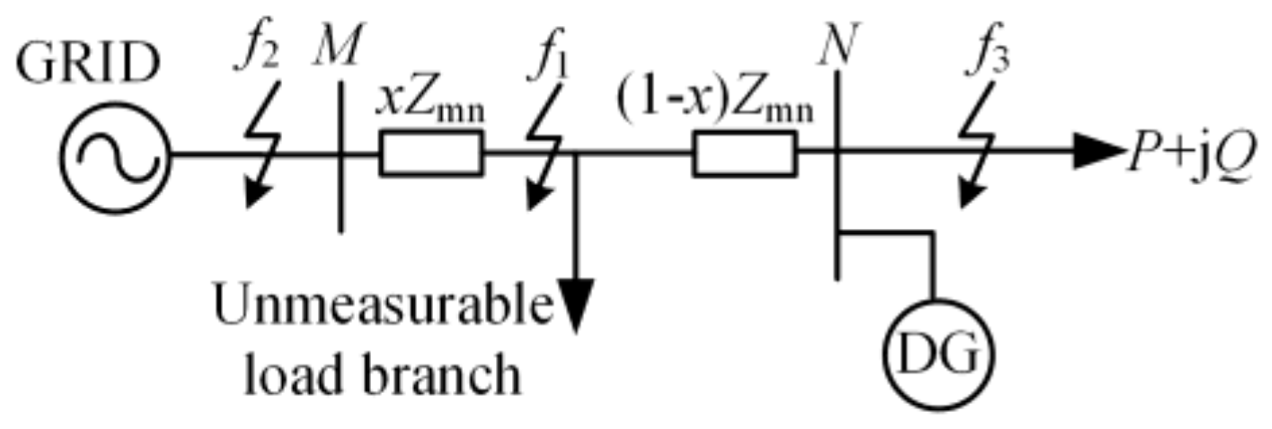
Figure 2.
Positive–sequence fault component composite sequence network with SBDG.
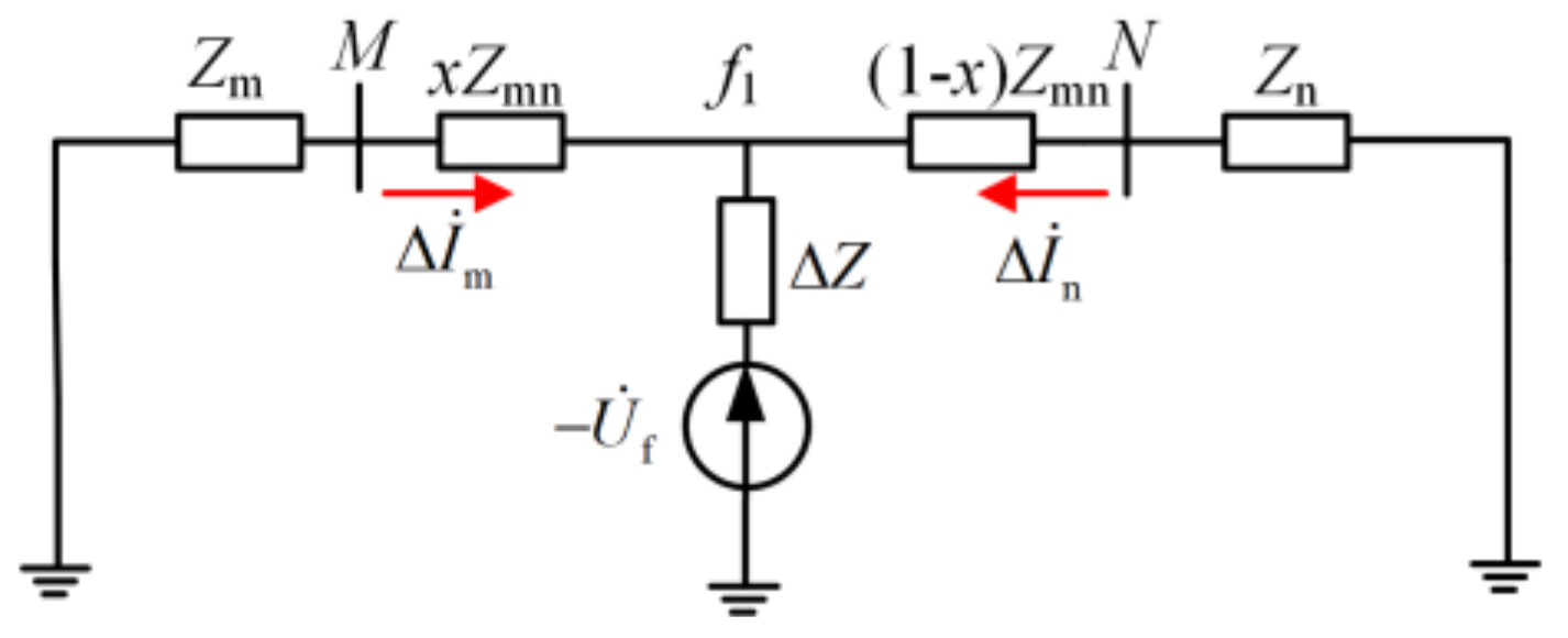
Figure 3.
Positive–sequence fault component composite sequence network with IBDG.
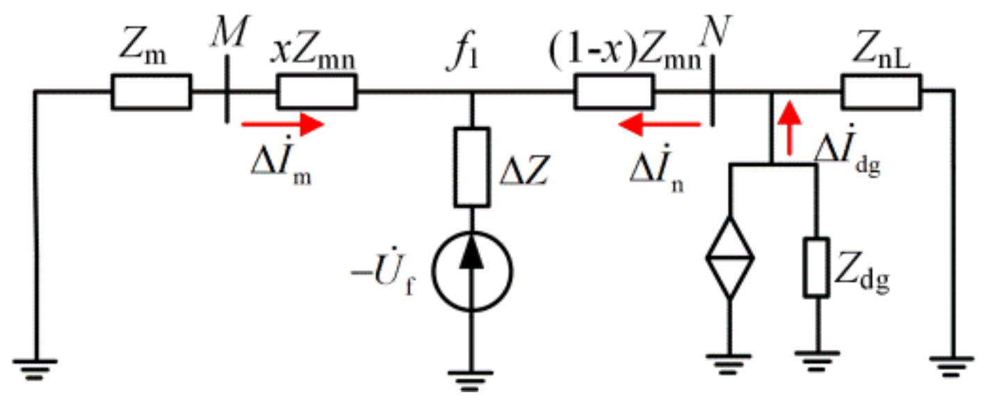
Figure 4.
The phase relationship between the output current of the IBDG and the voltage of the grid-connected point.
Figure 4.
The phase relationship between the output current of the IBDG and the voltage of the grid-connected point.
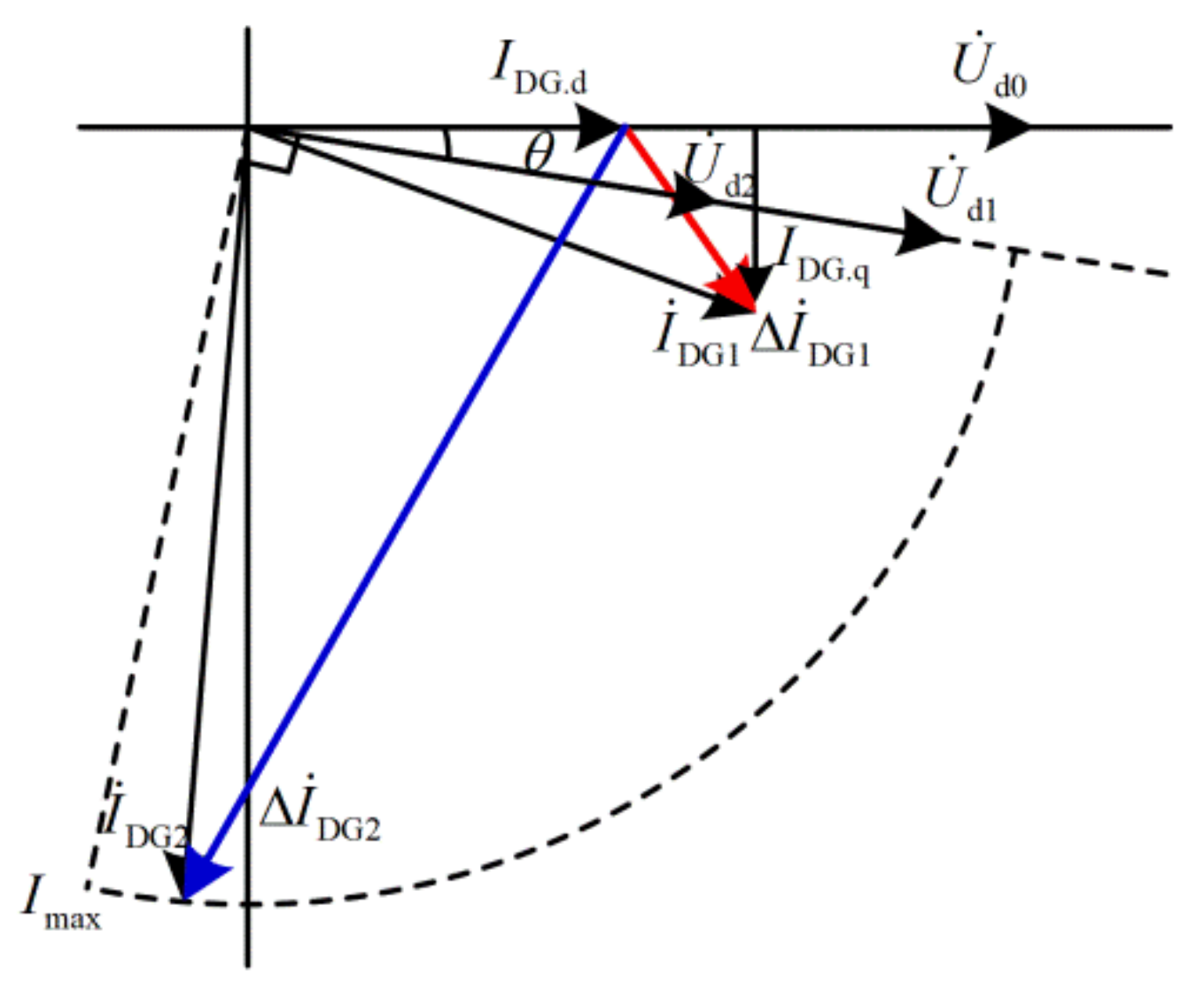
Figure 5.
Action characteristics of the TCDP in active distribute networks.
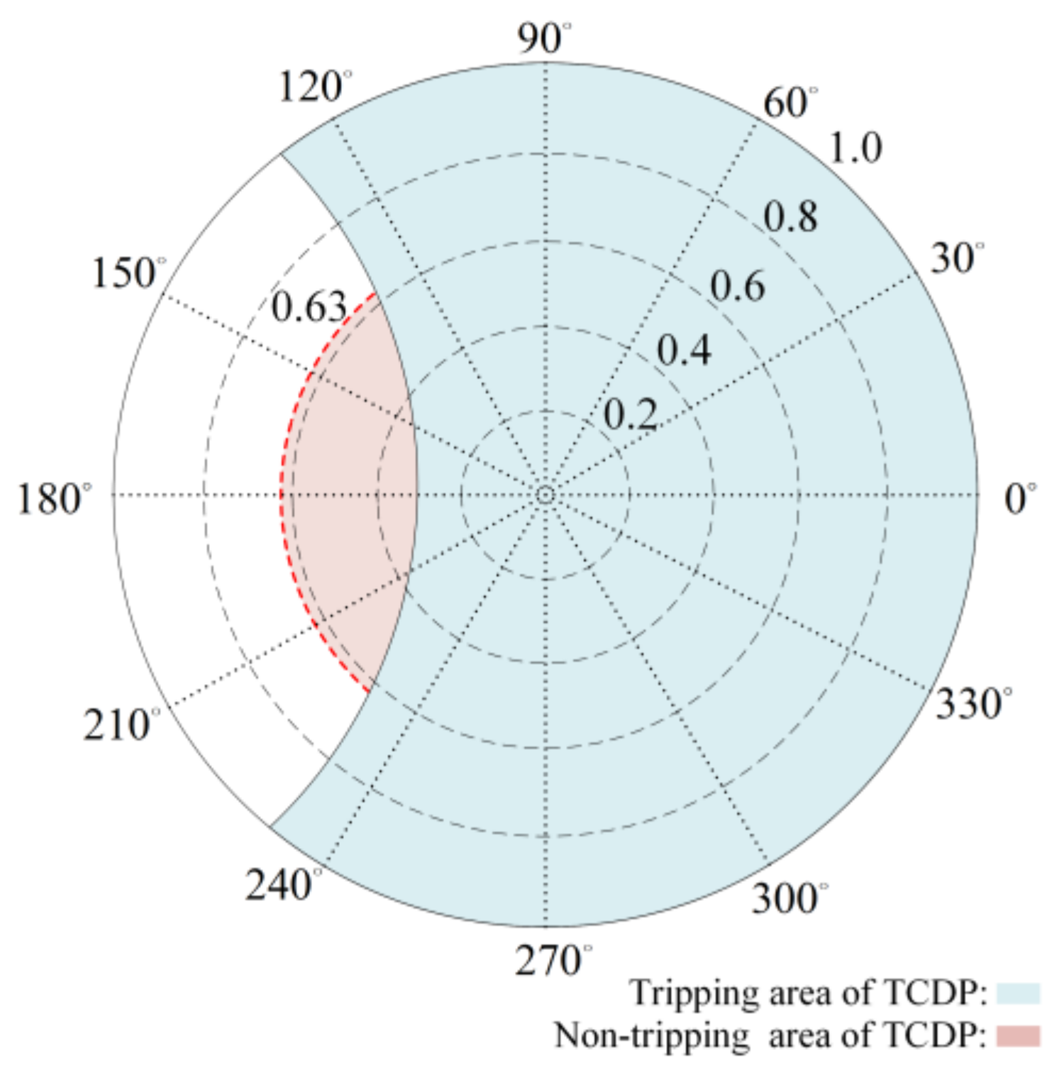
Figure 6.
Action characteristics of ACDP and TCDP in active distribute networks.
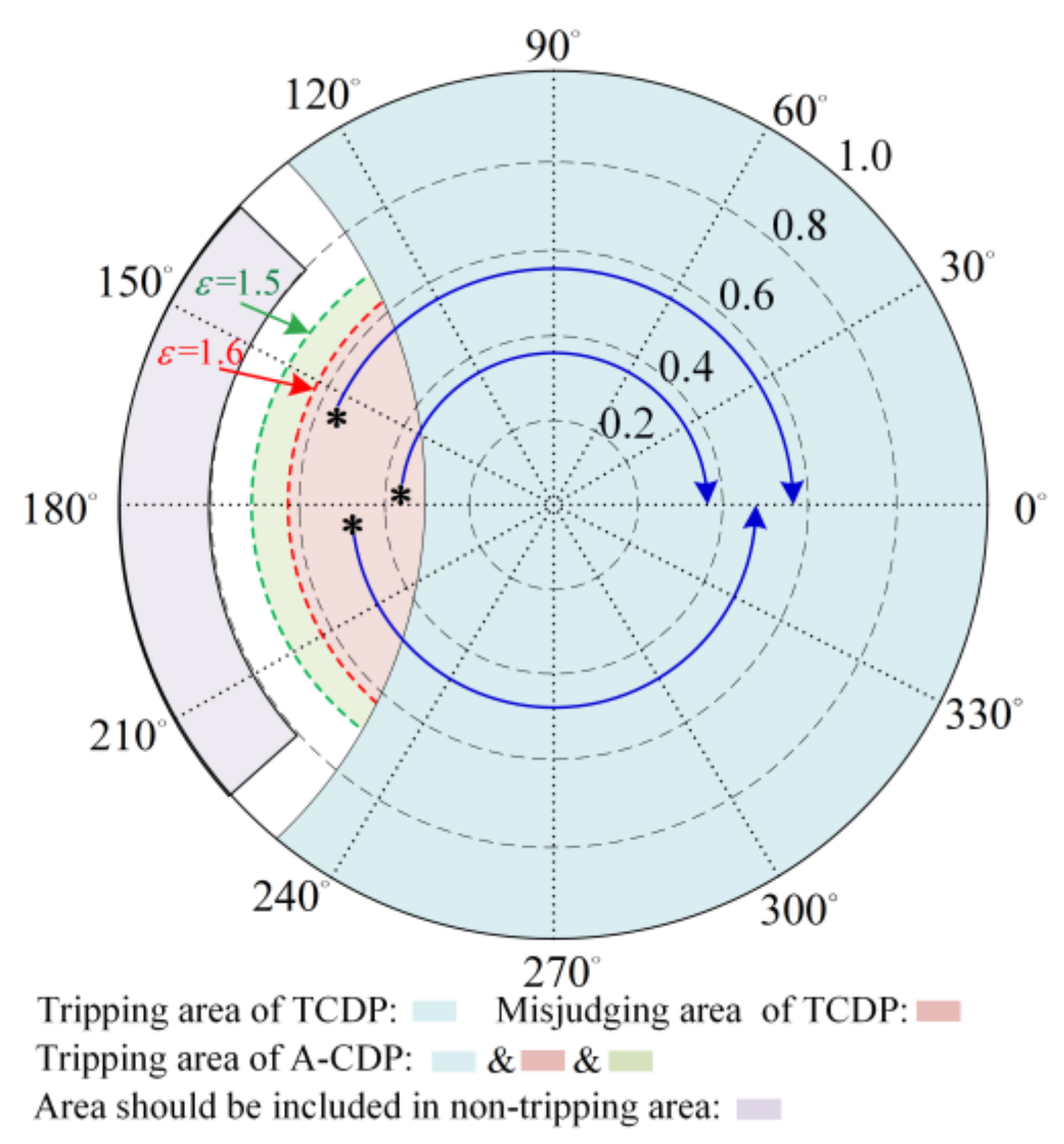
Figure 7.
Composite sequence network of the positive-sequence fault component: the UBL is upstream of the fault point in case of an internal fault.
Figure 7.
Composite sequence network of the positive-sequence fault component: the UBL is upstream of the fault point in case of an internal fault.

Figure 8.
Composite sequence network of the positive-sequence fault component: the UBL is downstream of the fault point in case of an internal fault.
Figure 8.
Composite sequence network of the positive-sequence fault component: the UBL is downstream of the fault point in case of an internal fault.
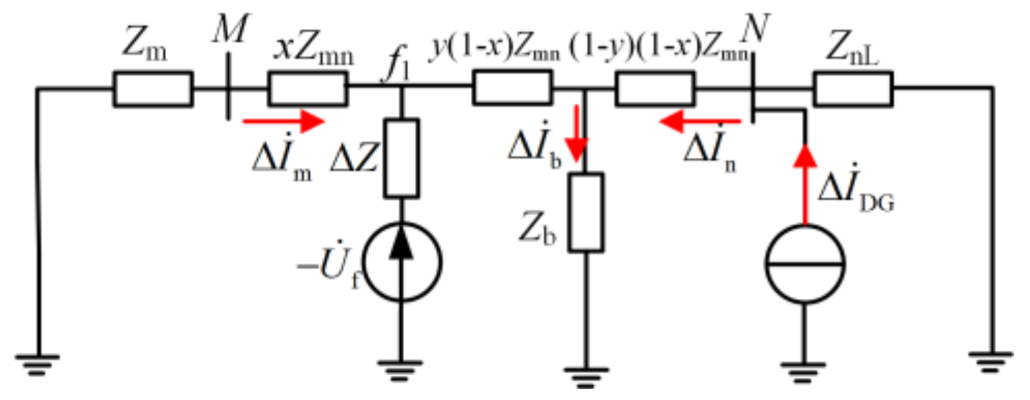
Figure 9.
Composite sequence network of the positive-sequence fault component: the UBL is downstream of the fault point in case of an external fault.
Figure 9.
Composite sequence network of the positive-sequence fault component: the UBL is downstream of the fault point in case of an external fault.
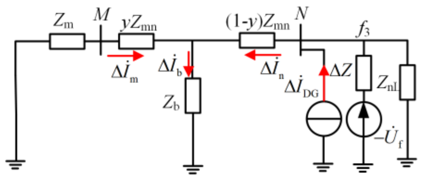
Figure 10.
Composite sequence network of the positive-sequence fault component: the UBL is upstream of the fault point in case of an external fault.
Figure 10.
Composite sequence network of the positive-sequence fault component: the UBL is upstream of the fault point in case of an external fault.
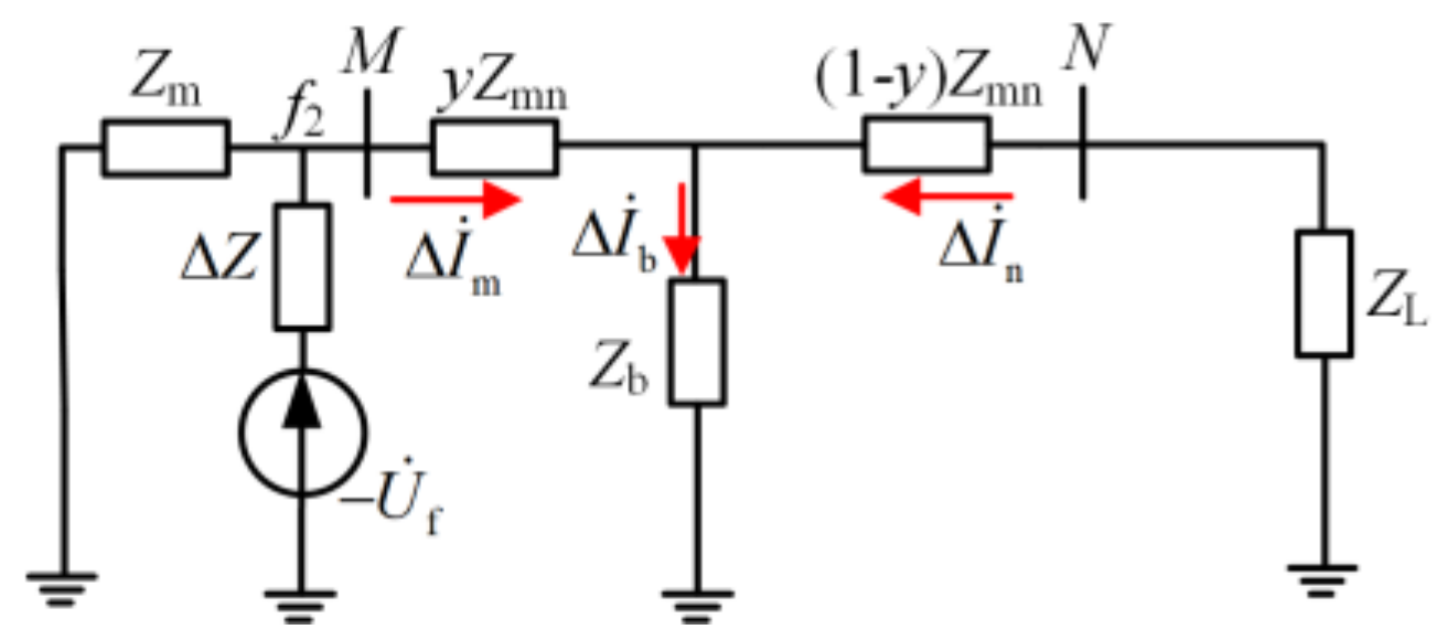
Figure 11.
Configuration process of the auxiliary criterion.

Figure 12.
Simple distribution network with DGs.

Figure 13.
Flowchart of the proposed protection scheme.
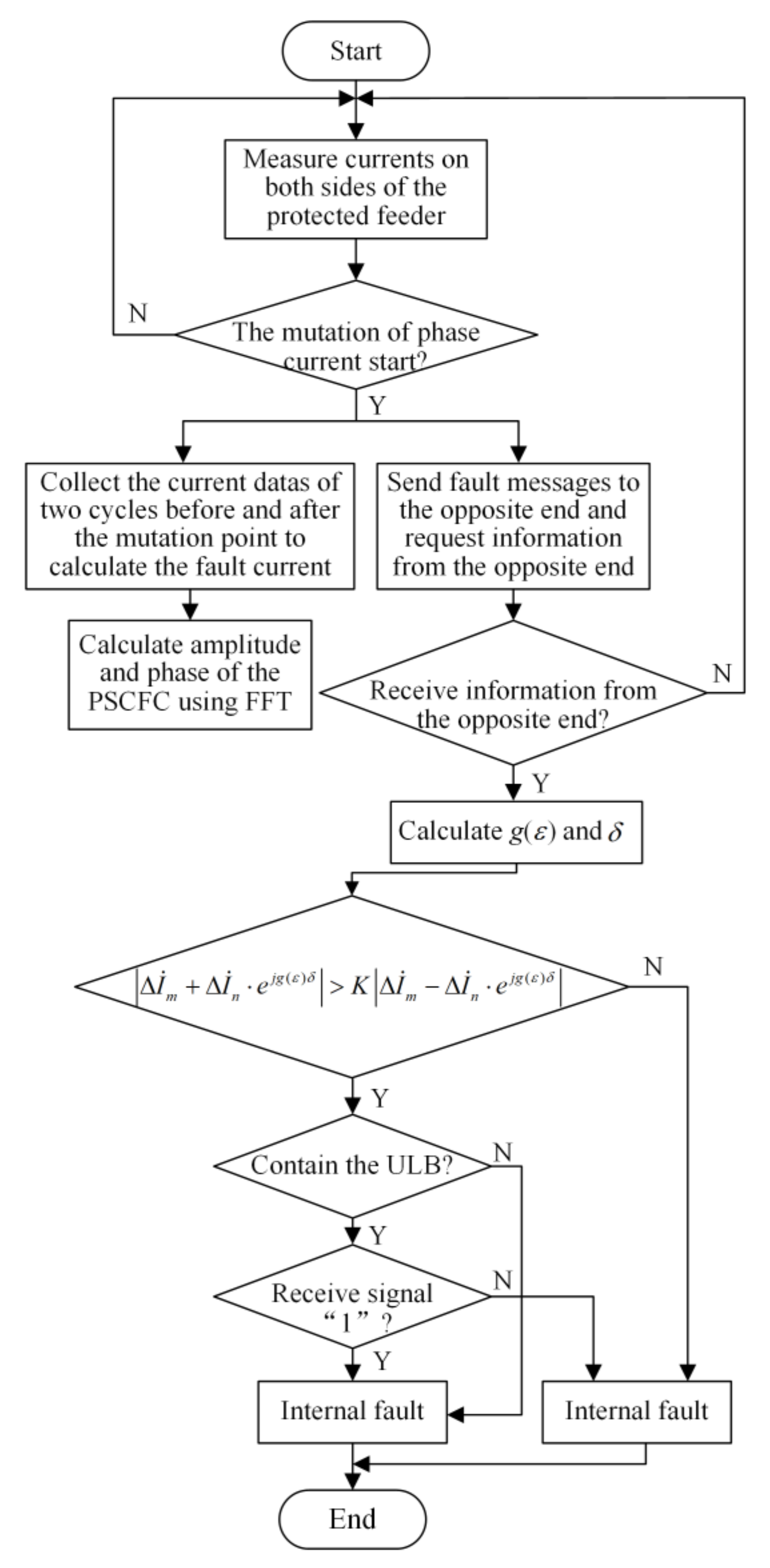
Figure 14.
Schematic of FDSS for active distribution network feeder protection.

Figure 15.
Fault record of a three-phase short-circuit fault with 2 Ω fault resistance occurs at f. (a) Currents at R1; (b) currents at R2; (c) the mutation of A-phase current at R1 and a three-phase current at R2.
Figure 15.
Fault record of a three-phase short-circuit fault with 2 Ω fault resistance occurs at f. (a) Currents at R1; (b) currents at R2; (c) the mutation of A-phase current at R1 and a three-phase current at R2.

Figure 16.
Schematic diagram of the active distribution network.


Table 1.
Parameters of the system model.
| Parameters | Values | Parameters | Values |
|---|---|---|---|
| Rated voltage | 10 kV | Capacity of DG4 | 4 MW |
| Capacity of grid | 50 MW | Capacity of L7 | (1.2 + j0.6) MVA |
| Capacity of DG1 | 2 MW | Capacity of other loads | (0.6 + j0.3) MVA |
| Capacity of DG2, DG3 | 2.5 MW |
Table 2.
Parameters of feeders.
| Parameters | Values | Parameters | Values |
|---|---|---|---|
| positive-sequence impedance | (0.13 + j0.402) Ω/km | Length of feeder section B5B6 | 5 km |
| Zero-sequence impedance | (0.26 + j0.87) Ω/km | Length of the other feeder sections | 4 km |
| Length of feeder sections B1B4 and B4B5 | 6 km |
Table 3.
Simulation results of metallic multi-phase faults at feeder B4B5.
| Fault Type | Fault Location | ε | δ/(rad) | Ksen | Trip or Not | ||
|---|---|---|---|---|---|---|---|
| ACDP | TCDP | ACDP | TCDP | ||||
| AB | 5% | 5.10 | −0.77 | 2.13 | 1.89 | Yes | Yes |
| 50% | 3.34 | −0.63 | 2.65 | 2.30 | Yes | Yes | |
| 95% | 2.21 | −0.46 | 3.79 | 3.23 | Yes | Yes | |
| ABG | 5% | 5.45 | −0.65 | 2.07 | 1.91 | Yes | Yes |
| 50% | 3.36 | −0.48 | 2.64 | 2.42 | Yes | Yes | |
| 95% | 2.18 | −0.25 | 3.85 | 3.64 | Yes | Yes | |
| ABC | 5% | 5.02 | 0.16 | 2.14 | 2.13 | Yes | Yes |
| 50% | 2.82 | −5.75 | 3.00 | 2.63 | Yes | Yes | |
| 95% | 2.00 | −5.60 | 4.29 | 2.97 | Yes | Yes | |
Table 4.
Simulation results of metallic multi-phase faults at feeder B7B8.
| Fault Type | Fault Location | ε | δ/(rad) | Ksen | Trip or Not | ||
|---|---|---|---|---|---|---|---|
| ACDP | TCDP | ACDP | TCDP | ||||
| AB | 5% | 2.21 | 0.21 | 3.79 | 3.65 | Yes | Yes |
| 50% | 1.23 | 0.22 | 9.33 | 9.33 | Yes | Yes | |
| 95% | 0.73 | 0.21 | 7.68 | 7.68 | Yes | Yes | |
| ABG | 5% | 2.22 | 0.22 | 3.77 | 3.63 | Yes | Yes |
| 50% | 1.20 | 0.24 | 9.44 | 9.44 | Yes | Yes | |
| 95% | 0.72 | 0.23 | 7.18 | 7.18 | Yes | Yes | |
| ABC | 5% | 2.26 | 0.25 | 3.70 | 3.53 | Yes | Yes |
| 50% | 1.25 | 0.23 | 8.89 | 8.89 | Yes | Yes | |
| 95% | 0.72 | 0.21 | 7.40 | 7.40 | Yes | Yes | |
Table 5.
Simulation results of ABg faults with high fault resistance at feeder B5B6.
| Fault Resistance | Fault Location | ε | δ/(rad) | Ksen | Trip or Not | ||
|---|---|---|---|---|---|---|---|
| ACDP | TCDP | ACDP | TCDP | ||||
| 25 Ω | 5% | 6.16 | 1.36 | 1.98 | 1.53 | Yes | Yes |
| 50% | 5.53 | 1.43 | 2.06 | 1.50 | Yes | Yes | |
| 95% | 2.89 | −4.37 | 2.94 | 1.16 | Yes | Yes | |
| 50 Ω | 5% | 9.61 | −4.44 | 1.76 | 1.35 | Yes | Yes |
| 50% | 4.07 | 1.48 | 2.36 | 1.49 | Yes | Yes | |
| 95% | 1.85 | 1.73 | 4.79 | 1.25 | Yes | Yes | |
| 100 Ω | 5% | 5.97 | −1.96 | 2.00 | 1.26 | Yes | Yes |
| 50% | 4.57 | −3.84 | 2.23 | 1.02 | Yes | Yes | |
| 95% | 2.47 | −3.67 | 3.37 | 0.71 | Yes | NO | |
| 150 Ω | 5% | 6.00 | −4.11 | 2.00 | 1.19 | Yes | Yes |
| 50% | 3.28 | −3.84 | 2.68 | 0.90 | Yes | NO | |
| 95% | 7.28 | −3.91 | 1.88 | 1.17 | Yes | Yes | |
Table 6.
Simulation results of the unmeasured load branch test.
| Fault Type | Fault Point | Fault Location | ε | δ/(rad) | Ksen | Zact | Trip or Not |
|---|---|---|---|---|---|---|---|
| AB | f1 | 5% | 4.53 | −0.92 | 2.24 | 0.14 | Yes |
| 50% | 2.35 | −0.63 | 2.04 | 1.19 | Yes | ||
| 95% | 2.26 | −0.28 | 3.70 | 0.47 | Yes | ||
| f2 | 5% | 0.86 | −3.20 | 0.12 | −0.27 | NO | |
| 50% | 0.86 | −3.20 | 0.12 | −1.40 | NO | ||
| 95% | 0.89 | −3.19 | 0.09 | −2.49 | NO | ||
| f3 | 5% | 1.60 | 2.94 | 6.19 | −2.50 | NO | |
| 50% | 1.56 | 2.99 | 6.53 | −1.62 | NO | ||
| 95% | 1.52 | 3.07 | 6.92 | −0.15 | NO | ||
| ABg | f1 | 5% | 4.22 | −0.73 | 2.32 | 0.15 | Yes |
| 50% | 2.78 | −0.27 | 3.03 | 1.21 | Yes | ||
| 95% | 2.28 | −0.13 | 2.56 | 0.47 | Yes | ||
| f2 | 5% | 0.87 | −3.22 | 0.08 | −0.27 | NO | |
| 50% | 0.88 | −3.20 | 0.10 | −1.42 | NO | ||
| 95% | 0.88 | −3.20 | 0.10 | −2.29 | NO | ||
| f3 | 5% | 1.49 | 2.97 | 0.29 | −2.09 | NO | |
| 50% | 1.50 | 3.00 | 0.29 | −1.46 | NO | ||
| 95% | 1.43 | 3.11 | 0.24 | −0.29 | NO | ||
| ABC | f1 | 5% | 4.94 | 0.11 | 2.15 | 0.64 | Yes |
| 50% | 2.92 | −5.90 | 2.92 | 0.43 | Yes | ||
| 95% | 2.36 | −5.60 | 3.53 | 0.41 | Yes | ||
| f2 | 5% | 0.85 | −3.24 | 0.14 | −0.23 | NO | |
| 50% | 0.85 | −3.24 | 0.14 | −1.49 | NO | ||
| 95% | 0.86 | −3.23 | 0.13 | −2.50 | NO | ||
| f3 | 5% | 1.61 | 3.22 | 6.12 | −1.77 | NO | |
| 50% | 1.55 | 3.34 | 6.62 | −1.00 | NO | ||
| 95% | 1.49 | 3.42 | 0.35 | −0.19 | NO |
Table 7.
Simulation results of time synchronization error test.
| Fault Resistance | Fault Location | Delay Time (ms) | ε | δ/(rad) | Ksen | Trip or Not | |||
|---|---|---|---|---|---|---|---|---|---|
| R7 | R8 | ACDP | TCDP | ACDP | TCDP | ||||
| 25 Ω | 5% | 0.1 | 3.6 | 6.15 | 2.46 | 1.98 | 1.11 | Yes | Yes |
| 50% | 0.1 | 4.1 | 5.36 | 2.72 | 2.08 | 1.02 | Yes | Yes | |
| 95% | 0.1 | 2.1 | 3.04 | −3.72 | 2.83 | 0.83 | Yes | NO | |
| 30 Ω | 5% | 0.1 | 4.6 | 6.71 | 2.84 | 1.93 | 1.07 | Yes | Yes |
| 50% | 0.1 | 4.2 | 4.58 | 2.96 | 2.23 | 0.92 | Yes | NO | |
| 95% | 0.1 | 2.1 | 3.03 | −3.29 | 2.84 | 0.72 | Yes | NO | |
Table 8.
Simulation results of DG4 out of operation during metallic multi-phase faults occur at feeder B7B8.
Table 8.
Simulation results of DG4 out of operation during metallic multi-phase faults occur at feeder B7B8.
| Fault Type | Fault Location | ε | δ/(rad) | Ksen | Trip or Not | ||
|---|---|---|---|---|---|---|---|
| ACDP | TCDP | ACDP | TCDP | ||||
| AB | 5% | 34.2 | −0.75 | 1.51 | 1.49 | Yes | Yes |
| 50% | 23.6 | −0.79 | 1.55 | 1.52 | Yes | Yes | |
| 95% | 18.0 | −0.79 | 1.60 | 1.54 | Yes | Yes | |
| ABG | 5% | 33.2 | −0.78 | 1.52 | 1.49 | Yes | Yes |
| 50% | 22.5 | −0.80 | 1.56 | 1.52 | Yes | Yes | |
| 95% | 16.9 | −0.81 | 1.61 | 1.55 | Yes | Yes | |
| ABC | 5% | 24.4 | −0.72 | 1.55 | 1.52 | Yes | Yes |
| 50% | 16.6 | −0.73 | 1.61 | 1.56 | Yes | Yes | |
| 95% | 12.7 | −0.75 | 1.67 | 1.61 | Yes | Yes | |
Disclaimer/Publisher’s Note: The statements, opinions and data contained in all publications are solely those of the individual author(s) and contributor(s) and not of MDPI and/or the editor(s). MDPI and/or the editor(s) disclaim responsibility for any injury to people or property resulting from any ideas, methods, instructions or products referred to in the content. |
© 2023 by the authors. Licensee MDPI, Basel, Switzerland. This article is an open access article distributed under the terms and conditions of the Creative Commons Attribution (CC BY) license (https://creativecommons.org/licenses/by/4.0/).
Share and Cite
MDPI and ACS Style
Yu, C.; Gao, Z.; Liu, Z.; Tao, Z. Current Differential Protection for Active Distribution Networks Based on Adaptive Phase Angle Compensation Coefficient. Appl. Sci. 2023, 13, 4723. https://doi.org/10.3390/app13084723
AMA Style
Yu C, Gao Z, Liu Z, Tao Z. Current Differential Protection for Active Distribution Networks Based on Adaptive Phase Angle Compensation Coefficient. Applied Sciences. 2023; 13(8):4723. https://doi.org/10.3390/app13084723
Chicago/Turabian StyleYu, Chengao, Zhanjun Gao, Zhao Liu, and Zhengchen Tao. 2023. "Current Differential Protection for Active Distribution Networks Based on Adaptive Phase Angle Compensation Coefficient" Applied Sciences 13, no. 8: 4723. https://doi.org/10.3390/app13084723
Note that from the first issue of 2016, this journal uses article numbers instead of page numbers. See further details here.