
A Method for Using GSM Technology and SCADA Systems to Monitor and Control Decommissioned and Partially Decommissioned Railway Stations
 ,
,
Abstract
:1. Introduction
2. Materials and Methods
2.1. The Initial Situation
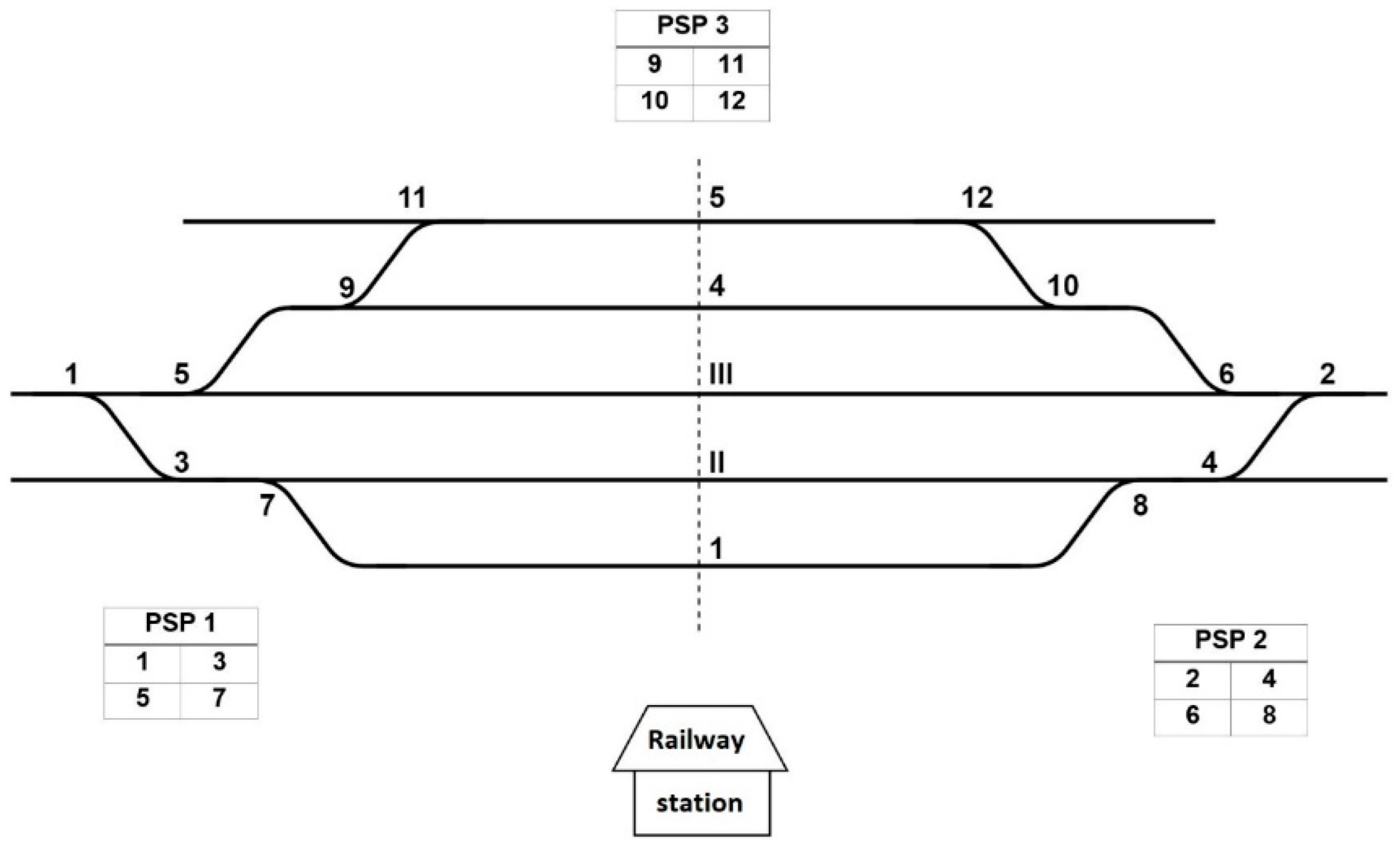
2.1.1. Rail Traffic and Handling Facilities
2.1.2. The Power Supply Installation of the Railway Station
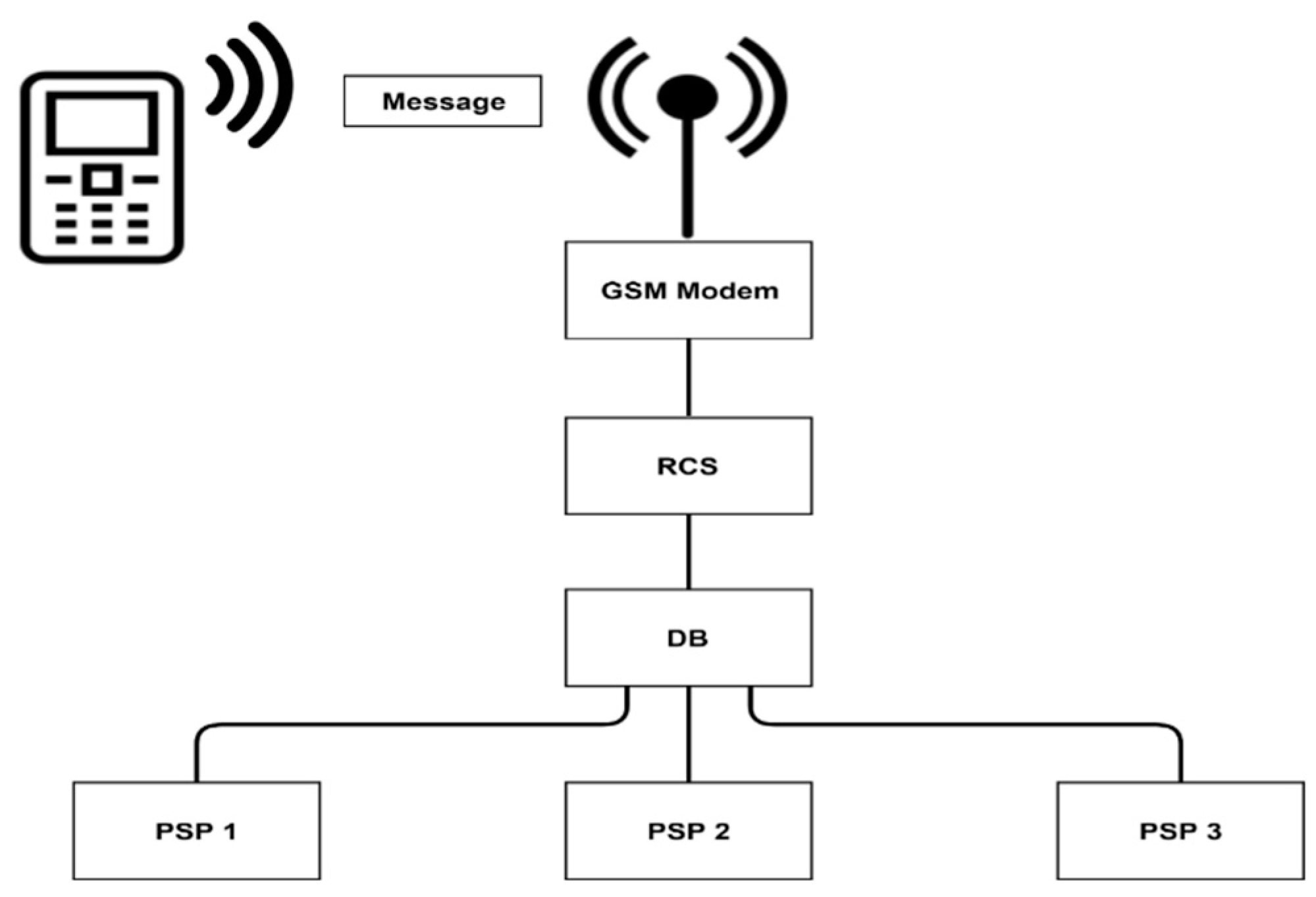
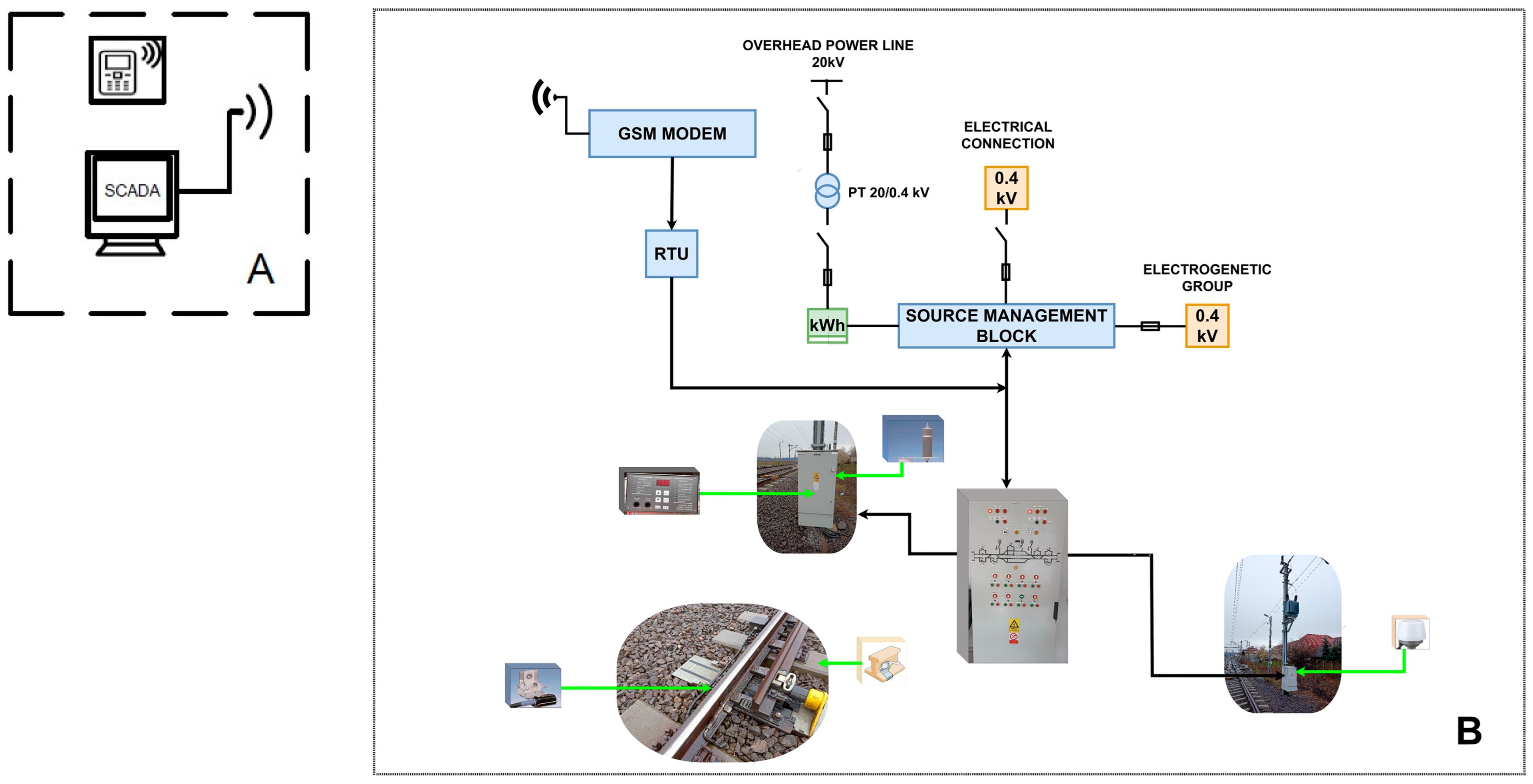
2.2. System Architecture
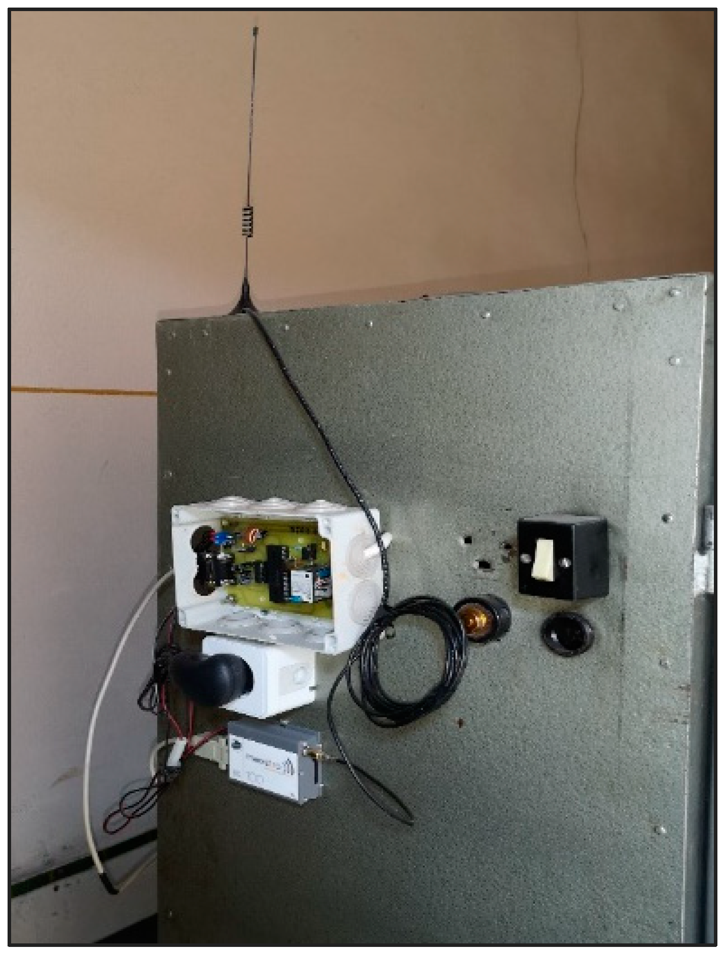
2.2.1. Initial Development
2.2.2. Software Description

- Replacement of the mobile terminal with the SCADA system implemented in the dispatch center;
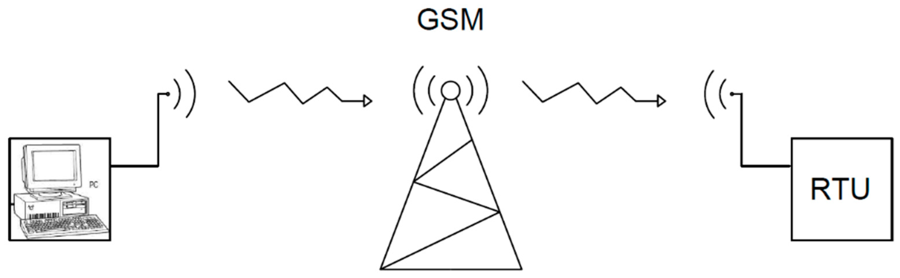
- Installation of an RTU connected to the GSM modem at the station;
- Outfitting of SMBs (source management blocks) and PSPs with digital relays.
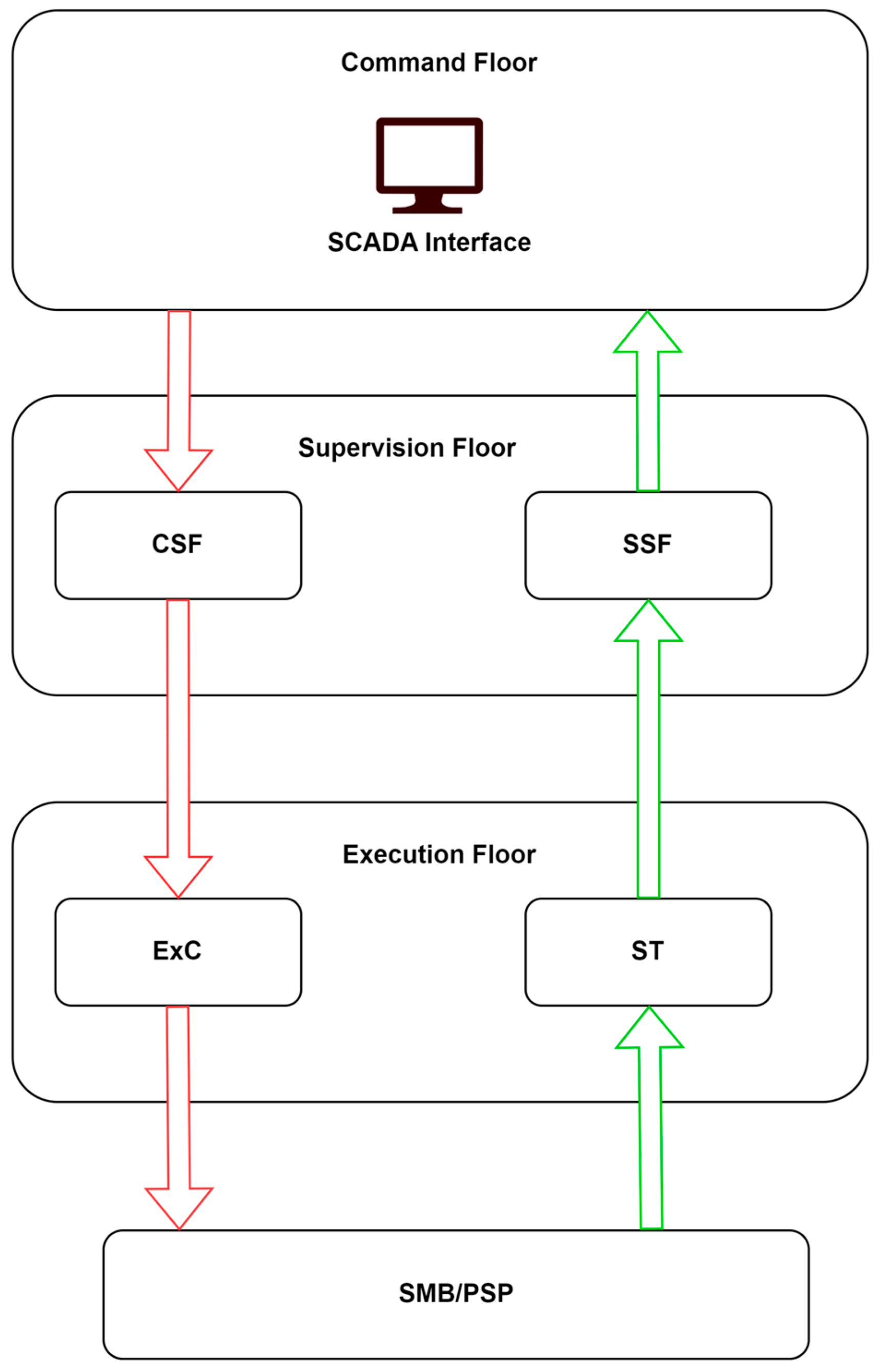
2.2.3. SCADA Functional Architecture
2.2.4. Security and Encryption
- 8 bits for the state (0 for off, 00001111 for on);
- 24 bits for the OTP;
- 256 bits for the shared key using AES encryption.
2.3. Delay Estimation Based on Train Traffic Data
- The occupancy rate of passenger trains should be between 90% and 100%;
- It should be a route with heavy traffic;
- It should be intended for commuting to the workplace for the majority of passengers;
- It should include partially or fully deactivated railway stations.
3. Results
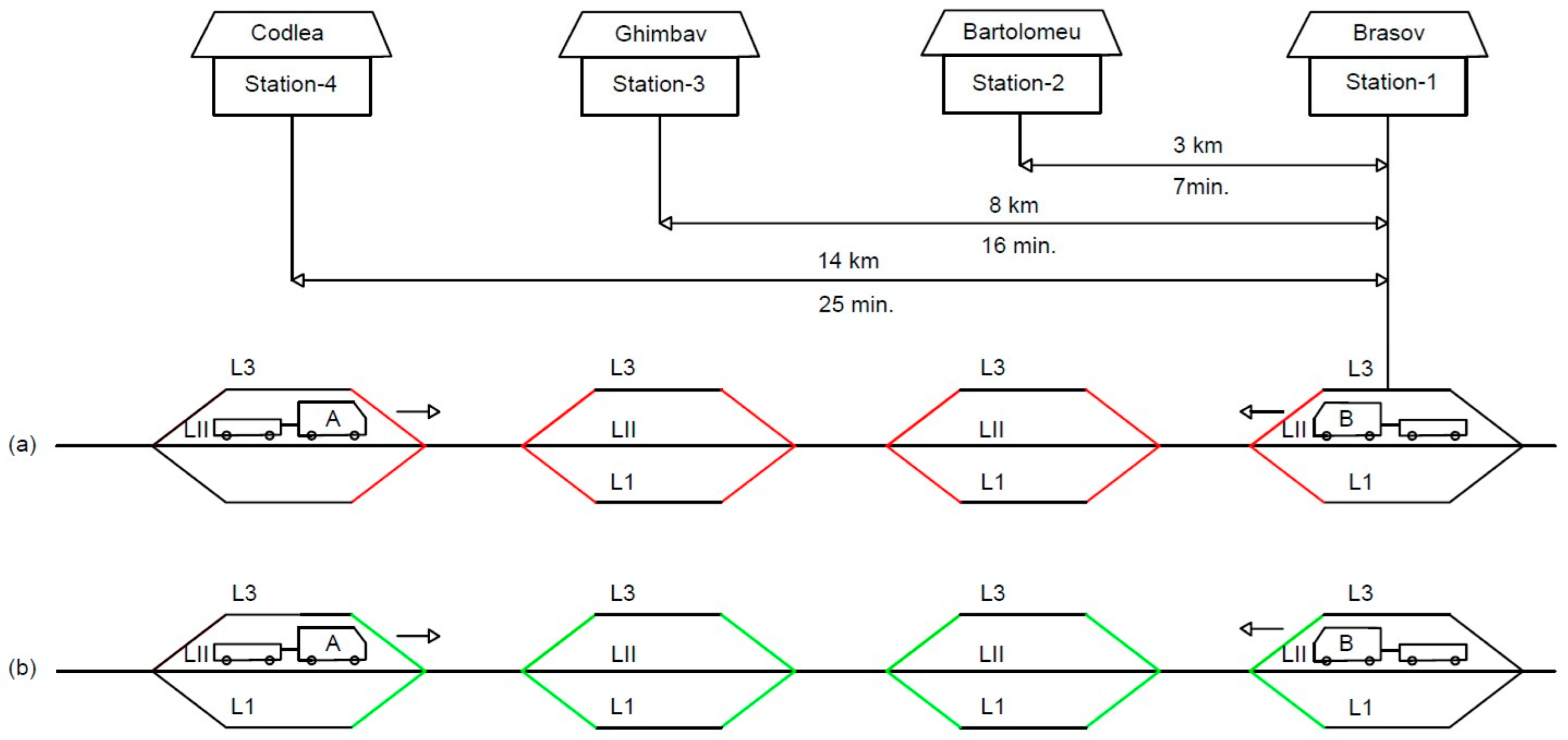
- Situation 1: L1 and L3 are unavailable at each railway station -> Train B departs from CF1 to CF4, Train A waits at CF4 for the arrival of Train B -> Train A arrives at CF1 with a delay of 25 min.
- Situation 2: L1 and L3 are available at each railway station -> Train B departs from CF1 to CF4, Train A departs from CF4 to CF3, the journey takes 9 min, and waits for Train B, which arrives after 7 min on Line 1 or 3. After this intersection, the trains continue their route, Train B arrives at CF4 according to the schedule, and Train A arrives at CF1 with a delay of only 7 min.
4. Discussion
- In Romania, the development and implementation of the SCADA system for the control of the railway transport system is just beginning, there are very few dispatching points and railway stations that are outfitted with this technology. For the quick resolution of this situation, it is recommended to implement the solution proposed here, mobile phone terminals and GSM modem based control;
- The control system was tested on a single railway. However, considering the comprehensive description of the GSM module, it is plausible that the proposed control system can be replicated by implementing the same system on other railways that possess decommissioned stations. Such an approach would enable a comparative analysis of the outcomes achieved, thus strengthening the generalizability of the findings.
- The research did not include the automation of train circulation, and for this reason there was the need to maintain operative service personnel in railway stations, authorized for the execution of maneuvers related to the effective movement of trains;
- The research could not be performed on a larger sample of railway stations, due to the lack of a digitized system providing a database with the necessary information. Ideally, the energy cost would be monitored using a dedicated procedure and module, as previously described [23];
- Although during the research period the limitations mentioned above were discovered, comparative analysis of the two situations shows that the solution developed and proposed in this paper requires a minimum financial effort to obtain important economic results.
5. Conclusions
Author Contributions
Funding
Institutional Review Board Statement
Data Availability Statement
Conflicts of Interest
References
- Küster, H. Railways: Gateways between east and west in Europe. Promet-Traffic Transp. 2003, 15, 215–221. [Google Scholar]
- Kuznetsov, A.A.; Lavrukhin, A.A.; Kuznetsova, M.A. Schemes and problems of scada system for electrical energy control on railway rolling stock. In Proceedings of the 2017 International Conference on Industrial Engineering, Applications and Manufacturing (ICIEAM), St. Petersburg, Russia, 16–19 May 2017. [Google Scholar]
- Clark, S. A historical overview of railway signalling & control (or ‘from Bobbies to Balises’). In Proceedings of the IET 13th Professional Development Course on Electric Traction Systems, London, UK, 3–6 November 2014; pp. 4–18. Available online: https://digital-library.theiet.org/content/conferences/10.1049/cp.2014.1433 (accessed on 13 March 2023).
- Ramuhulu, M.; Chiranga, N. An Investigation into the Causes of Failures in Railway Infrastructure at Transnet Freight Rail—A Case of the Steel and Cement Business Unit. Int. J. Sustain. Dev. World Policy 2018, 7, 8–26. [Google Scholar] [CrossRef] [Green Version]
- Longo, M.; Bramani, M. The automation control systems for the efficiency of metro transit lines. In Proceedings of the 2015 AEIT International Annual Conference (AEIT), Naples, Italy, 14–16 October 2015. [Google Scholar]
- European Union Agency for Railways. European Rail Traffic Management System (ERTMS). 2018. Available online: https://www.era.europa.eu/domains/infrastructure/european-rail-traffic-management-system-ertms_en (accessed on 12 March 2023).
- ETCS Levels and Modes. Available online: https://transport.ec.europa.eu/transport-modes/rail/ertms/how-does-it-work/etcs-levels-and-modes_en (accessed on 13 March 2023).
- Prasad, C. GSM-R to LTE for Railways in India. In Proceedings of the 2018 IEEE Global Conference on Wireless Computing and Networking (GCWCN), Lonavala, India, 23–24 November 2018. [Google Scholar]
- Holakar, A.; Mahendra, L.; Prasad, G.L.G.; Shetter, R. Secure interoperable gateway for wireless SCADA system. In Proceedings of the 2016 International Conference on Computation System and Information Proceedings of the Technology for Sustainable Solutions (CSITSS), Bengaluru, India, 6–8 October 2016; Available online: http://ieeexplore.ieee.org/document/7779408/ (accessed on 2 February 2023).
- Baldini, G.; Nai Fovino, I.; Masera, M.; Luise, M.; Pellegrini, V.; Bagagli, E.; Rubino, G.; Malangone, R.; Stefano, M.; Senesi, F. An early warning system for detecting GSM-R wireless interference in the high-speed railway infrastructure. Int. J. Crit. Infrastruct. Prot. 2010, 3, 140–156. [Google Scholar] [CrossRef]
- Analysis of Different Encryption Standards on GSM Network. Available online: https://www.ijser.org/paper/ANALYSIS-OF-DIFFERENT-ENCRYPTION-STANDARDS.html (accessed on 13 March 2023).
- Barausov, V.A.; Bubnov, V.P.; Sultonov, S.K. Designing Automatic Railway Switch Heating System with Innovative Intelligent Sensors. In Proceedings of the Intelligent Transport Systems and Transport Security, St.Petersburg, Russia, 14 May 2021. [Google Scholar]
- Barausov, V.A.; Bubnov, V.P.; Sultonov, S.K. Control Software for surface ice and snow detecting device. In Proceedings of the Models and Methods of Information Systems Research Workshop (MMISR 2019), St. Petersburg, Russia, 4–5 December 2019; CEUR Workshop Proceedings: St. Petersburg, Russia, 2019; Volume 2556, pp. 75–79. [Google Scholar]
- Barausov, V.A.; Bubnov, V.P.; Sultonov, S.K. Simulation modeling in methods and designs for detecting ice or snow buildup on control surface in MATLAB/SIMULINK dynamic modeling environment. In Proceedings of the Models and Methods of Information Systems Research Workshop 2020, St. Petersburg, Russia, 11–12 December 2020; CEUR Workshop Proceedings: St. Petersburg, Russia, 2020; pp. 136–141. [Google Scholar]
- Golovash, A.N.; Esipenko, V.S.; Pimenov, I.Y. Switch Heating Device Bibliographic Data. Patent RU2232222 (C1) 2004, 15 March 2019. [Google Scholar]
- Yantang, G. Electric Heating Snow Removing Device For Railway Points Bibliographic Data. Patent CN201433383 (Y), 31 March 2010. [Google Scholar]
- Baruchov, V.A.; Kochubey, V. Electrical Heating Device Of Track Switches Type Seit-04 Bibliographic Data. Patent RU2582627 (C1), 27 April 2016. [Google Scholar]
- Popov, A.; Bratu, D.; Moraru, S. Remote Control of Railway Switch Heating Using GSM Modems. Ann. Dunarea Jos Univ. Galati Fascicle IX Metall. Mater. Sci. 2019, 42, 42–47. [Google Scholar] [CrossRef]
- Xuesong, F.; Hanxiao, Z.; Yong, D.; Zhili, L.; Hongqin, P.; Bin, X. A Review Study on Traction Energy Saving of Rail Transport. Discret. Dyn. Nat. Soc. 2013, 2013, 156548. [Google Scholar] [CrossRef] [Green Version]
- Syed, H.R.U.; Zaman, H.; Hanif, M. Scada Implementation Using Gsm Network For Communication. In Proceedings of the International Conference on Embedded Systems and Applications (ESA), Las Vegas, NV, USA, 18 July 2011; The Steering Committee of The World Congress in Computer Science, Computer Engineering and Applied Computing: Athens, Greece, 2011. [Google Scholar]
- Pan, D. GSM Remote Controler Heater, Technology and Comunication 2014. Available online: https://www.theseus.fi/handle/10024/79408 (accessed on 17 January 2023).
- Lukman, A.; Olayemi, M.O.; Kolo, J.; Ajao, A. Project-Based Microcontroller System Laboratory Using Bk300 Development Board With PIC16F887 Chip. Int. J. Embed. Syst. Appl. (IJESA) 2015, 5, 15–28. [Google Scholar]
- ARC Electronics, RS232 Tutorial on Data Interface and Cables. Available online: http://www.arcelect.com/rs232.htm/ (accessed on 10 August 2022).
- Parab, J.S.; Shelake, V.G.; Kamat, R.K.; Naik, G.M. Exploring C for Microcontrollers: A Hands on Approach; Springer: New York, NY, USA, 2007; pp. 50–76. [Google Scholar]
- Katte, S.; Kotecha, D.; Vora, J.; Mehendale, N. Wireless SCADA technology using GPRS. Technofocus 2011, 2, 37–40. Available online: https://www.researchgate.net/publication/305083329_Wireless_SCADA_technology_using_GPRS (accessed on 7 January 2023).
- Dange, A.; Fernando, E.; Zachariah, H.S.; Kallakuri, D. Real-time Alert System for Auxiliary Transformer Failures. In Proceedings of the 2022 IEEE International Students’ Conference on Electrical, Electronics and Computer Science (SCEECS), Bhopal, India, 19–20 February 2022. [Google Scholar] [CrossRef]
- Popov, A.; Fratu, A.; Lepadat, I.; Helerea, E.; Cojanu, V. Monitoring the Cost of Energy for Powering the Railway Electric Traction System. In Proceedings of the 2019 8th International Conference on Modern Power Systems (MPS), Cluj Napoca, Romania, 21–23 May 2019; pp. 1–6. Available online: https://ieeexplore.ieee.org/document/8759724 (accessed on 6 January 2023).
- European Standard for the Automatic Train Protection (ATP)—Romania. Available online: https://transport.ec.europa.eu/transport-modes/rail/ertms/contributing/countries/romania_en (accessed on 14 March 2023).
- Rajkumar, R.I.; Sundari, G. Intelligent computing hardware for collision avoidance and warning in high speed rail networks. J. Ambient. Intell. Humaniz. Comput. 2020, 1–13. [Google Scholar] [CrossRef]
- Site-ul Administratiei Nationale de Meteorologie. Available online: https://web.archive.org/web/20090906221054/http://www.meteoromania.ro/index.php?id=489 (accessed on 14 March 2023).


| Passenger trains | Situation 1 | Difference/Year (Minutes) | Difference/Year (Cost) | |||||
| No. trains/24 h | Delay/24 h (minutes) | Delay/month (minutes) | Delay/year (minutes) | Cost/minute | Cost/year | |||
| 14 | 350 | 10,850 | 3,960,250 | 12.3 | 48,711,075 | 7,700,989 | 36,041,895.8 | |
| Freight trains | Situation 1 | |||||||
| No. trains/24 h | Delay/24 h (minutes) | Delay/month (minutes) | Delay/year (minutes) | Cost/minute | Cost/year | |||
| 10 | 500 | 15,500 | 5,657,500 | 0.2 | 1,131,500 | |||
| Passenger trains | Situation 2 | |||||||
| No. trains/24 h | Delay/24 h (minutes) | Delay/month (minutes) | Delay/year (minutes) | Cost/minute | Cost/year | |||
| 14 | 98 | 3038 | 1,108,870 | 12.3 | 13,639,101 | |||
| Freight trains | Situation 2 | |||||||
| No. trains/24 h | Delay/24 h (minutes) | Delay/month (minutes) | Delay/year (minutes) | Cost/minute | Cost/year | |||
| 10 | 71.4 | 2213.4 | 807,891 | 0.2 | 161,578.2 | |||
Disclaimer/Publisher’s Note: The statements, opinions and data contained in all publications are solely those of the individual author(s) and contributor(s) and not of MDPI and/or the editor(s). MDPI and/or the editor(s) disclaim responsibility for any injury to people or property resulting from any ideas, methods, instructions or products referred to in the content. |
© 2023 by the authors. Licensee MDPI, Basel, Switzerland. This article is an open access article distributed under the terms and conditions of the Creative Commons Attribution (CC BY) license (https://creativecommons.org/licenses/by/4.0/).
Share and Cite
Popov, A.-F.; Kristaly, D.M.; Bratu, D.-V.; Zolya, M.-A.; Moraru, S.-A. A Method for Using GSM Technology and SCADA Systems to Monitor and Control Decommissioned and Partially Decommissioned Railway Stations. Appl. Sci. 2023, 13, 4874. https://doi.org/10.3390/app13084874
Popov A-F, Kristaly DM, Bratu D-V, Zolya M-A, Moraru S-A. A Method for Using GSM Technology and SCADA Systems to Monitor and Control Decommissioned and Partially Decommissioned Railway Stations. Applied Sciences. 2023; 13(8):4874. https://doi.org/10.3390/app13084874
Chicago/Turabian StylePopov, Alexandru-Florian, Dominic Mircea Kristaly, Dragoș-Vasile Bratu, Maria-Alexandra Zolya, and Sorin-Aurel Moraru. 2023. "A Method for Using GSM Technology and SCADA Systems to Monitor and Control Decommissioned and Partially Decommissioned Railway Stations" Applied Sciences 13, no. 8: 4874. https://doi.org/10.3390/app13084874