
Efficient Zero-Sequence Impedance Measurement in Autotransformers Using Low-Voltage Excitation
by
Min Zhang
1,*,
Jian Fang
1,
Hongbin Wang
1,
Qingdan Huang
1,
Haicheng Hong
1,
Xiang Lin
1 and
Niancheng Zhou
2 1
Guangdong Power Grid Co., Ltd., Guangzhou Power Supply Bureau, No. 2, Tianhe South 2nd Road, Tianhe District, Guangzhou 510620, China
2
State Key Laboratory of Power Transmission Equipment & System Security and New Technology, Chongqing University, Shapingba District, Chongqing 400044, China
*
Author to whom correspondence should be addressed.
Appl. Sci. 2024, 14(1), 215; https://doi.org/10.3390/app14010215
Submission received: 17 September 2023
/
Revised: 7 December 2023
/
Accepted: 22 December 2023
/
Published: 26 December 2023
(This article belongs to the Topic High Voltage Systems and Smart Technologies)
Abstract
:In accordance with the IEEE standard, the zero-sequence impedance test of transformers necessitates an open or short circuit test on the high-voltage side winding. Power source excitation is applied to the high-voltage test winding using a high-capacity test power supply. To circumvent the need for a large-capacity, high-voltage test power supply in field tests, this paper proposes a method for measuring zero-sequence impedance in autotransformers based on low-voltage excitation and disconnection testing. By applying a three-phase power supply to the lowest voltage side of the autotransformer and creating a disconnection condition, an unbalanced test scenario is established. Subsequently, the composite sequence network equivalent circuit for one-phase and two-phase disconnections between the high-voltage side and the low-voltage side of the transformer is formulated. Calculation formulas for the zero-sequence impedance of the autotransformer under various conditions are derived. The accuracy of the zero-sequence impedance is verified using MATLAB/Simulink simulation software 2018b, evaluating double-winding and three-winding autotransformers in breaking tests under different connection modes. The error is found to be less than 3%. The results of this study affirm the high accuracy of the proposed method.
1. Introduction
Power transformers are power equipment for transmitting electrical energy in power systems. In ultra-high-voltage, high-capacity grids of 220 kV and above, the main transformers used include ordinary conventional transformers and autotransformers; the characteristics of both transformers are shown in Table 1 [1,2]. Autotransformers are widely used because of their small size, low cost, large-capacity, high operating efficiency and high short circuit resistance. In the design stage of power systems, there are generally no strict requirements for the size and deviation of the transformer’s zero-sequence impedance, nor are there clear calculation formulas; furthermore, the estimation methods are currently used [3]. However, accurate transformer zero-sequence impedance is an important basis for power system analysis, short circuit current zero-sequence component calculation, quantification of transformer short circuit resistance, selection of relay protection devices and calculation of protection calibration values [4,5]. Therefore, it is important to obtain accurate values of transformer zero-sequences from tests [6,7].
The information on the transformer parameters is tested by the transformer manufacturer in a series of factory tests before the product leaves the factory, and is recorded in the product’s factory report. However, only the positive-sequence parameters of the transformer are included in these tests. The zero-sequence impedance measurement of three-phase transformers is a special test that is carried out by mutual agreement between the transformer manufacturer and the user department [3,8]. The standard method for measuring the zero-sequence impedance of an autotransformer is given in IEEE Std C57.12.90 [9], which describes two short circuit tests and two open circuit tests with zero-sequence voltages applied to different ports; then, any three of these values are combined to solve for the zero-sequence impedance of the autotransformer [10,11,12]. The standard test method is able to measure the zero-sequence impedance of auto-transformers accurately. However, one set of short circuit tests needs to be carried out on the high-voltage side. This test requires special instrumentation and equipment, which is costly for field tests on transformers already in operation, and sometimes impossible due to site constraints [13].
Considering the shortcomings of the standard test method, the literature [14] proposes a method for low-voltage measurement of the zero-sequence equivalent circuit parameters of three-phase, three-winding YNynd-type transformers. However, the test current only measures 1–4% of the rate current because it uses a low-voltage test on the high-voltage side, and this phenomenon can lead to large measurement errors. The literature [15,16] proposes a method for estimating the zero-sequence impedance of transformers using finite element modelling. However, the method requires knowledge of the specific transformer geometry, winding arrangement and the properties of the core material. To reduce the difficulty of the test, ensure the personal safety of the staff and facilitate field testing, a method for measuring the low-voltage side of the zero-sequence impedance of transformers was proposed in the literature [17]. The method replaces the high-voltage side open circuit test required in the standard test with a low-voltage side disconnection test, mainly for the zero-sequence impedance equivalent circuit of conventional isolation type transformers, and it does not analyze autotransformers, which are widely used in high-capacity grids.
This paper presents a zero-sequence impedance measurement method for autotrans-formers based on low-voltage excitation and disconnection tests for the field measurement. Firstly, a model for calculating the zero-sequence impedance of autotransformers was derived by combining the disconnection test and the disconnection position, and from this, the formula for calculating the zero-sequence impedance under different test conditions was obtained. Then, combined with the remaining two sets of open circuit and short circuit tests on the LV side, a complete set of methods for measuring the zero-sequence impedance of autotransformers on the LV side is formed. Finally, the feasibility of this method is demonstrated by comparing the results with standard test results through simulation verification of different test conditions. The method in this paper allows the measured value of the high-voltage side short circuit test in the standard method to be obtained through the low-voltage side test, which is applicable to all autotransformers and traditional transformers that are not Y-connected. As a result, the method greatly reduces the cost of field testing and the requirement for a site.
2. YNa Autotransformer Zero-Sequence Impedance Field Test Method
2.1. One-Phase Disconnection Test on the High-Voltage Side
The wiring for the one-phase disconnection test on the high-voltage side of an autotransformer with YNa connection is shown in Figure 1 (phase A as the special phase).
The test is achieved by applying a three-phase power source on the low-voltage side, leaving the A-phase winding on the high-voltage side open, and the remaining two phases short circuited to earth. The corresponding complex sequence network is shown in Figure 2. Here, ZH-1, ZH-2 and ZH-0 are the positive-, negative- and zero-sequence impedances of the three phases on the high-voltage side of the autotransformer, respectively; ZL-1, ZL-2 and ZL-0 are the positive-, negative- and zero-sequence impedances of the three phases on the low-voltage side, respectively; Zg-0 is the zero-sequence excitation impedance. The core structure of automatic transformers usually adopts a three-column core design [x]. In this construction, the core of the transformer consists of three cylindrical sections, each of which is wrapped around a winding. This design is common in three-phase transformers and allows for efficient transfer of electrical energy. It is worth noting that the automatic transformer has only one winding, in which different parts of the same winding serve as both the main winding and the secondary winding of the transformer [18]. Therefore, the zero-sequence flux can only form a closed loop through the oil gap and the box, as shown in Figure 3. This makes the reluctance of the zero-sequence flux large, while the excitation reactance is small and cannot be ignored. Based on Figure 3, the zero-sequence impedance can be expressed as:
The leakage impedance of the autotransformer is inductive, and the proportion of resistance value is small, so it can be ignored to simplify the calculation. Figure 3 can be considered as a purely inductive circuit. Phases of each sequence current vector are the same. The vector relationship can be expressed directly in terms of numerical magnitude:
Here, , , are the difference between two different phase line currents on the low-voltage side of the autotransformer, respectively, and are positive-sequence currents; I1, I2, I0 are negative- and zero-sequence currents.
From Equation (3), it can be seen that the real part of and is the same, and the imaginary part is opposite. Assume that the angle between and is θ, , and . It can be found that:
Then it can be found that:
The phase angles of , , are the same, and the relationship between line voltage and sequence voltage is the same as that of the current in Equation (3). Therefore, by assuming that = = V, the angle between and is φ, and it can be found that:
Similar to what is shown in Figure 4, it can be solved that:
Substituting Equation (6) into Equation (1) can obtain the zero-sequence impedance of the autotransformer:
2.2. One-Phase Disconnection Test on Low-Voltage Side
The wiring diagram for the one-phase disconnection test on the low-voltage side is similar to Figure 2. The test requires a three-phase power supply to be applied to the low-voltage side, with the low-voltage side A-phase winding being open circuited, while the high-voltage side winding is short circuited to earth in three phases. The composite sequential network is shown in Figure 5, and corresponding zero-sequence impedance is shown in Equation (1).
Equations (4) and (5) also apply to the low-voltage side of a phase disconnection test. Therefore, the zero-sequence impedance of the autotransformer is:
2.3. Two-Phase Disconnection Test on the High-Voltage Side
The wiring diagram for the two-phase disconnection test on the high-voltage side is shown in Figure 6 (phases B and C are the test phases). The test requires the application of a three-phase power supply on the low-voltage side and open circuiting of the B- and C-phase windings on the high-voltage side, with the A-phase winding short circuited to earth, which corresponds to the composite sequence network shown in Figure 7. Based on I1 = I2 = I0, it follows that the relationship of the phase sequence current on the low-voltage side A is:
The sequence voltage can be solved according to Equation (7), and then the zero-sequence impedance of the autotransformer is:
2.4. Two-Phase Disconnection Test on the Low-Voltage Side
The two-phase disconnection test on the low-voltage side requires the application of a three-phase power supply on the low-voltage side, open circuiting the two-phase winding on the low-voltage side and short circuiting the winding on the non-power side to ground. The corresponding compound sequence network is the same as Figure 7.
The phase sequence voltage relationship is shown in Equation (11):
Based on Equation (11), it can be found that . Therefore, the current-voltage vector diagram for each phase sequence is shown in Figure 8. The corresponding compound sequence network is a three-sequence series connection. Given this, the sequence current relationship is the same as Equation (9), which can be substituted into Equation (10) to obtain the zero-sequence impedance of this autotransformer.
The sequential voltage expressions in the above tests are universal. The difference in them lies in the different angles of the different disconnection tests. For example, in the two-phase disconnection test on the high-voltage side, the negative-sequence voltage V2 is in the opposite phase to the positive-sequence voltage V1 due to three equal sequence currents, and this phenomenon makes the angle between and increase.
3. YNa0d11 Three-Winding Autotransformer Zero-Sequence Impedance Field Test Method
3.1. One-Phase Disconnection Test
The connection between the high- and medium-voltage sides of the YNa0d11 autotransformer is star grounding, with the low-voltage side being the triangle connection. To measure the zero-sequence equivalent impedance of individual windings, the following 3 disconnection tests are required on the low-voltage side:
- (1)
- Tset 1: Positive-sequence excitation on the low-voltage side; while one phase of the high-voltage winding is disconnected, the other two phases are short circuited to earth and the medium-voltage winding is completely disconnected.
- (2)
- Tset 2: Positive-sequence excitation on the low-voltage side; while one phase of the medium-voltage winding is disconnected, the other two phases are short circuited to earth and the high-voltage winding is completely disconnected.
- (3)
- Tset 3: Positive-sequence excitation on the low-voltage side; while one phase of the medium- and the high-voltage winding is disconnected, the other two phases are short circuited to earth.
Tests 1 and 2 have similar test content and wiring methods, measuring the zero-sequence impedance to ground of the high-voltage side ZHg-0 and the medium-voltage side ZTg-0, respectively. Here, ZHg-0 = ZH-0 = ZH-0 + Zg-0, ZTg-0 = ZT-0 + Zg-0. The connection for Test 1 is illustrated in Figure 9. The subscripts “a, b, c” in Figure 9 represent the parameters on the low-voltage side of the transformer.
The zero-sequence impedance of this autotransformer can be derived from the composite sequence network diagram in Figure 10 as ZHg-0 = (V1 I1 ZHL-1)/I0. Considering the phase variations introduced by different connection methods, the Yd-11 coupling method, more commonly used in power systems, is taken as an example. In this method, the positive-sequence component of the voltage and current on the low-voltage side of the autotransformer leads the high- and medium-voltage side by 30°, while the negative-sequence component lags the high- and medium-voltage side by 30°. The phase relationship between current and voltage is shown in Figure 11. Therefore, it can be found that:
Based on Equation (12), and have the same imaginary part, and opposite real parts. By assuming that and the angle between and is θ, it can be found that:
By assuming that and combining this with Equation (5), it can be found that:
By combining Equations (14) and (15), the zero-sequence impedance ZHg-0 can be found, as well as ZTg-0. The test connection for Test 3 is illustrated in Figure 12. The subscripts “a, b, c” in Figure 12 represent the parameters on the low-voltage side of the transformer. The test involves applying a three-phase voltage source to the low-voltage side of the transformer, with the high- and medium-voltage sides both open circuited in phase A and short circuited to earth in phases B and C. The transformer sequence component network diagram under Experiment 3 is shown in Figure 13.
The three tests above give the zero-sequence impedance of the 3 windings.
3.2. Two-Phase Disconnection Test
The two-phase disconnection test is similar to the same-phase disconnection test. It also requires three tests of disconnection on the high with low-voltage side, the medium with low-voltage side, with the high- and medium-voltage side results being:
- (1)
- Test 4: Positive-sequence excitation is injected on the low-voltage side; the high-voltage side winding is grounded in one phase and disconnected in two phases and the low-voltage side winding is completely disconnected.
- (2)
- Test 5: Positive-sequence excitation is injected on the low-voltage side; the medium-voltage side winding is grounded in one phase and disconnected in two phases and the high-voltage side winding is completely disconnected.
- (3)
- Test 6: Positive-sequence excitation is injected on the low-voltage side and both high- and medium-voltage windings are single-phase grounded and two-phase disconnected.
Both Test 4 and Test 5 are wired similarly to measure the zero-sequence impedance to ground on the high-voltage side ZHg-0 and the zero-sequence impedance to ground on the medium-voltage side ZTg-0, respectively. Test 4 is wired as illustrated in Figure 14. The subscripts “a, b, c” in Figure 14 represent the parameters on the low-voltage side of the transformer.
The zero-sequence impedance of this autotransformer can be derived from the compound sequence network diagram in Figure 15.
and can be obtained by combining Equations (15) and (18).
The test wiring for Test 6 is shown in Figure 16 and the corresponding composite sequence network diagram is shown in Figure 17. The subscripts “a, b, c” in Figure 16 represent the parameters on the low-voltage side of the transformer.
The three tests described above lead to three sets of zero-sequence impedances.
The zero-sequence impedance of each winding of the autotransformer can be found separately by using Equation (18).
In this paper, the theoretical analysis of both the one-phase and two-phase disconnection tests on the high-voltage side of YNa0d11-type autotransformers is described.
The flowchart of the testing method proposed in this article is shown in Figure 18.
4. Simulation Verification
4.1. Double-Winding Autotransformer One-Phase and Two-Phase Disconnection Test
The method in this paper can be applied to the measurement of the zero-sequence impedance of different autotransformers. Low-voltage field tests can be carried out using common commercial UPS power supplies with a rated voltage of 380 V and a power size of 500 kVA. To verify the practicality of the proposed method, a simulation model of a 31.5 MVA 220/66 kV three-phase, three-column YNa-type autotransformer was constructed in MATLAB/Simulink 2018b. The parameters of the testing transformer are shown in Table 2. Simulation verification of one-phase and two-phase disconnection tests was carried out, and the results are illustrated in Table 3 and Table 4.
In accordance with the pertinent national standards for oil-immersed transformers, the positive-sequence short circuit impedance ZHL-1 in Equations (7), (9) and (11) can be assumed as 11%. Additionally, the values of V and I used in calculating the zero-sequence impedance can be taken as the averages of Vab and Vca, and Iab and Ica, respectively. Comparing the calculated results with the standard values, the error for the one-phase disconnection test on the high-voltage side is 1.88%; for the one-phase disconnection test on the low-voltage side, it is −2.01%. In the case of the two-phase disconnection test, the errors are 0.73% and 1.15% on the high- and low-voltage sides, respectively.
As evident from the provided table, the proposed disconnection test method demonstrates a higher accuracy in calculating the zero-sequence impedance of a double-winding autotransformer. In comparison to the standard measurement method, the error in calculating the zero-sequence impedance of the transformer using the low-voltage disconnection test is less than 2%.
4.2. YNa0d11 Autotransformer One-Phase and Two-Phase Disconnection Test
To verify the low-voltage measurement method of the three-winding autotransformer disconnection test proposed in this paper, a simulation model of a YNa0d11 autotransformer (63 MVA 220/121/36 KV) was built in Simulink. The positive-sequence short circuit impedance is 28% for , 19% for and 9% for . Table 5 and Table 6 show the measurement results of the different wire disconnection tests.
The theoretical analysis and simulation validation involve model simplifications and equivalence measures to streamline calculations. While these measures may introduce some errors into the final simulation results, the accuracy of the proposed method’s measurements is found to be within 3%, based on the conclusive results. The observed error is sufficiently small, making the method suitable for power system protection adjustment and short circuit current calculation.
5. Conclusions
This paper addresses the shortcomings of the zero-sequence impedance measurement method for autotransformers as specified in the ANSI/IEEE standard, which is not easy to implement in the field, and proposes a disconnected test method for measuring the zero-sequence impedance of autotransformers in the field with power applied to the low-voltage side. The conclusions can be drawn as follows:
- (1)
- Using the disconnection test to measure the zero-sequence impedance of the transformer to be tested, the test power supply is placed on the low-voltage side of the transformer, reducing the difficulty and complexity of the test and reducing the cost of the test while enabling the field measurement of the zero-sequence impedance of autotransformers.
- (2)
- According to the proposed method, the test results were simulated and compared to the standard measurement method. Although there were some errors, the overall error was less than 3%, which proved the practicality of the proposed method, which could be used in engineering practice.
This paper derives the measurement and calculation formulas for the zero-sequence impedance of two-winding and three-winding autotransformers, and obtains a suitable testing method for the zero-sequence impedance of autotransformers. Finally, the proposed wire breakage test method was used to simulate and verify the dual-winding and three-winding autotransformers. The simulation results showed that the method has high accuracy, with an impedance percentage error of less than 3%. In order to facilitate calculations in the theoretical analysis of the proposed method, a pure inductance model was used for the transformer. Although the zero-sequence impedance value that can be used in engineering practice can be obtained, ignoring the resistance value in the zero-sequence impedance will still have a certain impact on the experimental calculation results. Further research is needed to improve the accuracy of this method.
Author Contributions
Conceptualization, M.Z., J.F. and N.Z.; methodology, M.Z.; software, J.F. and H.W.; validation, Q.H. and H.H.; writing—original draft preparation, M.Z. and J.F.; writing—review and editing, X.L., H.H., M.Z. and Q.H. All authors have read and agreed to the published version of the manuscript.
Funding
This work was funded by the science and technology project of Guangdong power grid Co., Ltd. (funder: China Southern Gaming Co., Ltd., funding number: GZHKJXM20200083).
Institutional Review Board Statement
Not applicable.
Informed Consent Statement
Not applicable.
Data Availability Statement
Data are contained within the article.
Conflicts of Interest
Author Min Zhang, Jian Fang, Hongbin Wang, Qingdan Huang, Haicheng Hong, Xiang Lin were employed by the company Guangdong Power Grid Co., Ltd. Guangzhou Power Supply Bureau. The remaining authors declare that the research was conducted in the absence of any commercial or financial relationships that could be construed as a potential conflict of interest. The authors declare that they have no known competing financial interests or personal relationships that could have appeared to influence the work reported in this paper. The authors declare that this study received funding from China Southern Gaming Co., Ltd. The funder was not involved in the study design, collection, analysis, interpretation of data, the writing of this article or the decision to submit it for publication.
Nomenclature
| Variables | Explanation |
| I1, I2, I0 | Positive-, negative-, and zero-sequence components of current I |
| V1, V2, V0 | Positive-, negative-, and zero-sequence components of voltage V |
| Z1, Z2, Z0 | Positive-, negative-, and zero-sequence components of impedance Z |
| ZH-1, ZH-2, ZH-0 | Positive-, negative-, and zero-sequence components of high-voltage impedance ZH |
| ZL-1, ZL-2, ZL-0 | Positive-, negative-, and zero-sequence components of low-voltage impedance ZL |
| Zg-0 | Zero-sequence excitation impedance |
| , , | Line current between two different phases |
| , , | Line voltage between two different phases |
References
- Wang, J.; He, B. Novel Step-Up Topologies of Zigzag Autotransformer. Electronics 2021, 10, 3071. [Google Scholar] [CrossRef]
- Nina, S.; Bozidar, F.-G.; Marijan, P. Impact of autotransformer inrush currents on differential protection operation. Electr. Power Syst. Res. 2023, 220, 109309. [Google Scholar]
- Das, S.; Ananthan, S.N.; Santoso, S. Estimating zero-sequence impedance of three-terminal transmission line and Theveninimpedance using relay measurement data. Prot. Control Mod. Power Syst. 2018, V3, 373–382. [Google Scholar]
- Fang, T.; Qian, Y.; Guo, C.; Song, C.; Wang, Z.; Luo, J.; Quanke, B.A. Reasearch on transformer fault diagnosis based on a beetle antennae search optimized support vector machine. Power Syst. Prot. Control 2020, 48, 90–96. [Google Scholar]
- Oves, A.G.; Mehrdad, M.; Mehdi, E.-A. A fault data based method for zero-sequence impedance estimation of mutually coupled transmission lines. IEEE Trans. Power Deliv. 2021, 36, 2768–2776. [Google Scholar]
- He, Q.; He, G.; Li, Z.; Lin, M.; Zhang, G.; Li, X. Pilot protection based on zero-sequence current resistance-capacitance component for large-scale inverter-interfaced power stations. Sustainability 2022, 14, 13268. [Google Scholar] [CrossRef]
- Aristotelis, M.T.; Vassilis, C.N. Setting zero-sequence compensation factor in distance relays protecting distribution systems. IEEE Trans. Power Deliv. 2018, 33, 1236–1246. [Google Scholar]
- Yuan, D.; Yin, Z.; Wang, S.; Duan, N. Multi-level transient modeling of the aeronautic asymmetric 18-pulse phase-shifting auto-transformer rectifier in full-cycle design. IEEE Trans. Transp. Electrif. 2022, 8, 3759–3770. [Google Scholar] [CrossRef]
- IEEE Std C57.12.90; IEEE Standard Test Code for Liquid-Immersed Distribution, Power, and Regulating Transformers. IEEE: New York, NY, USA, 2010.
- Liang, H.; Li, H.; Wang, G. A single-phase-to-ground fault detection method based on the ratio fluctuation coefficient of the zero-sequence current and Voltage differential in a distribution network. IEEE Access 2023, 11, 7297–7308. [Google Scholar] [CrossRef]
- Quilumba, F.L.; Jimerson, R.E.; Swift, K.; Garcia, R. Positive- and zero-sequence impedance estimation of YNyn0+d-connected main power transformers in wind power applications. CSEE J. Power Energy Syst. 2021, 7, 57–65. [Google Scholar]
- Bogomolov, V.; Lovo, Y.; Kokhan, P. Fault current levels in 220 and 500 kV autotransformer circuits. Electr. Technol. 1981, 2, 30–37. [Google Scholar]
- Kamel, M.; Saeed, H.; Karrar, A.; Eltom, A.H. On-site low voltage determination of zero-sequence impedances for station auxiliary transformers. In Proceedings of the 2016 IEEE Power and Energy Society General Meeting (PESGM), Boston, MA, USA, 17–21 July 2016; pp. 1–5. [Google Scholar]
- Ramos, A.; Burgos, J.C.; Moreno, A.; Sorrentino, E. Determination of Parameters of Zero-Sequence Equivalent Circuits for Three-Phase Three-Legged YNynd Transformers Based on Onsite Low-Voltage Tests. IEEE Trans. Power Deliv. 2013, 28, 1618–1625. [Google Scholar] [CrossRef]
- Allcock, R.; Holland, S.; Haydock, L. Calculation of zero phase sequence impedance for power transformers using numerical methods. IEEE Trans. Magn. 1995, 31, 2048–2051. [Google Scholar] [CrossRef]
- Wu, Q.; Jazebi, S.; de Leon, F. Parameter Estimation of Three-Phase Transformer Models for Low-Frequency Transient Studies from Terminal Measurements. IEEE Trans. Magn. 2017, 53, 8107108. [Google Scholar] [CrossRef]
- Saeed, H.; Kamel, M.; Karrar, A.; Eltom, A.H.; Bowman, M. On-Site Low Voltage Determination of Zero-Sequence Impedances for Power Transformers. IEEE Trans. Power Deliv. 2020, 35, 1048–1057. [Google Scholar] [CrossRef]
- Chapman, S.J. Electric Machinery Fundamentals; McGraw-Hill: New York, NY, USA, 2004. [Google Scholar]
Figure 1.
YNa autotransformer test diagram for the high-voltage side One-Open-Phase method.

Figure 2.
Sequence network of the YNa autotransformer high-voltage One-Open-Phase test.
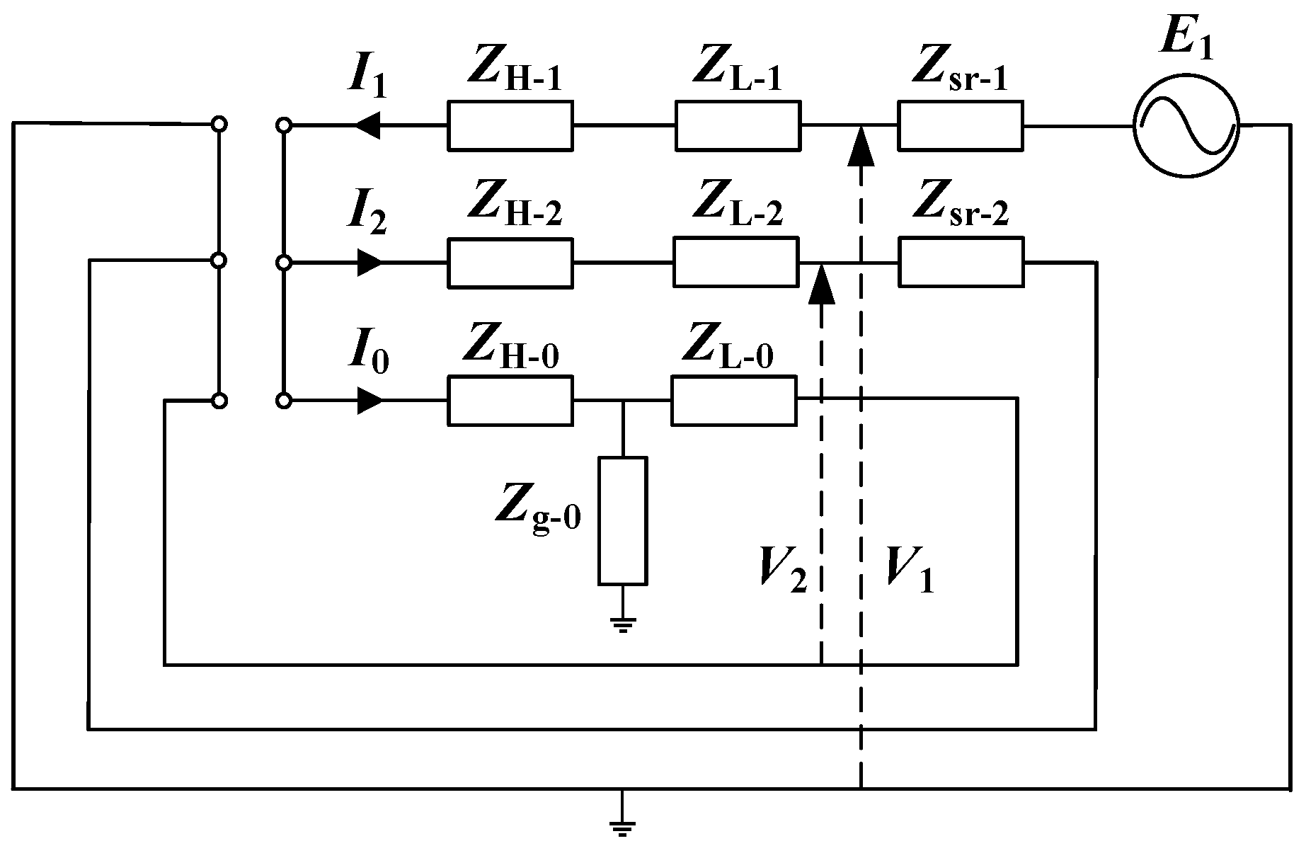
Figure 3.
The magnetic circuit of the zero-sequence flux. (a) Core and zero-sequence magnetic flux path. (b) Induced current in the fuel tank wall.
Figure 3.
The magnetic circuit of the zero-sequence flux. (a) Core and zero-sequence magnetic flux path. (b) Induced current in the fuel tank wall.
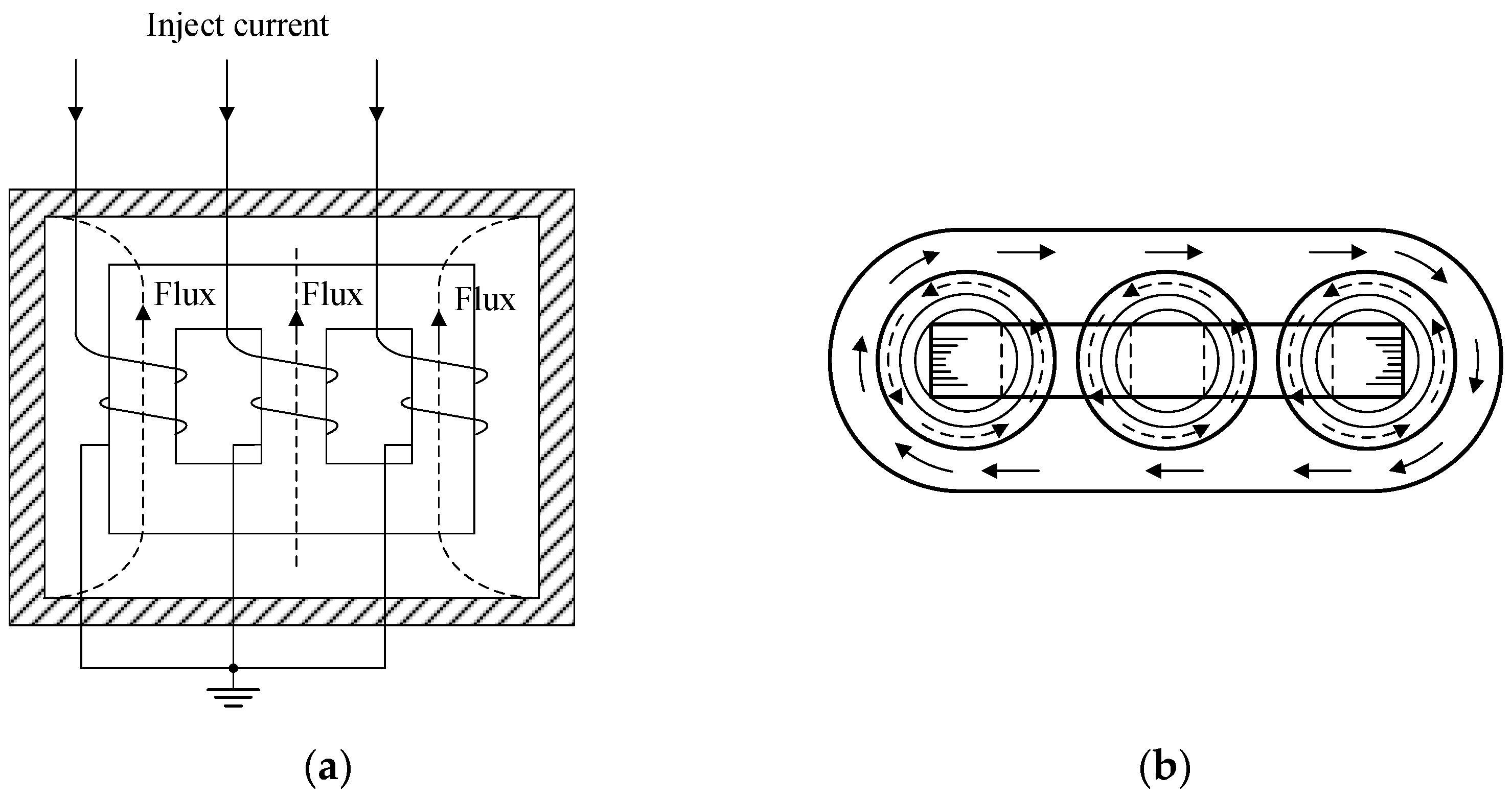
Figure 4.
Phasor diagram of secondary voltage/currents for the high-voltage One-Open-Phase test.

Figure 5.
Sequence network of the YNa autotransformer low-voltage One-Open-Phase test.
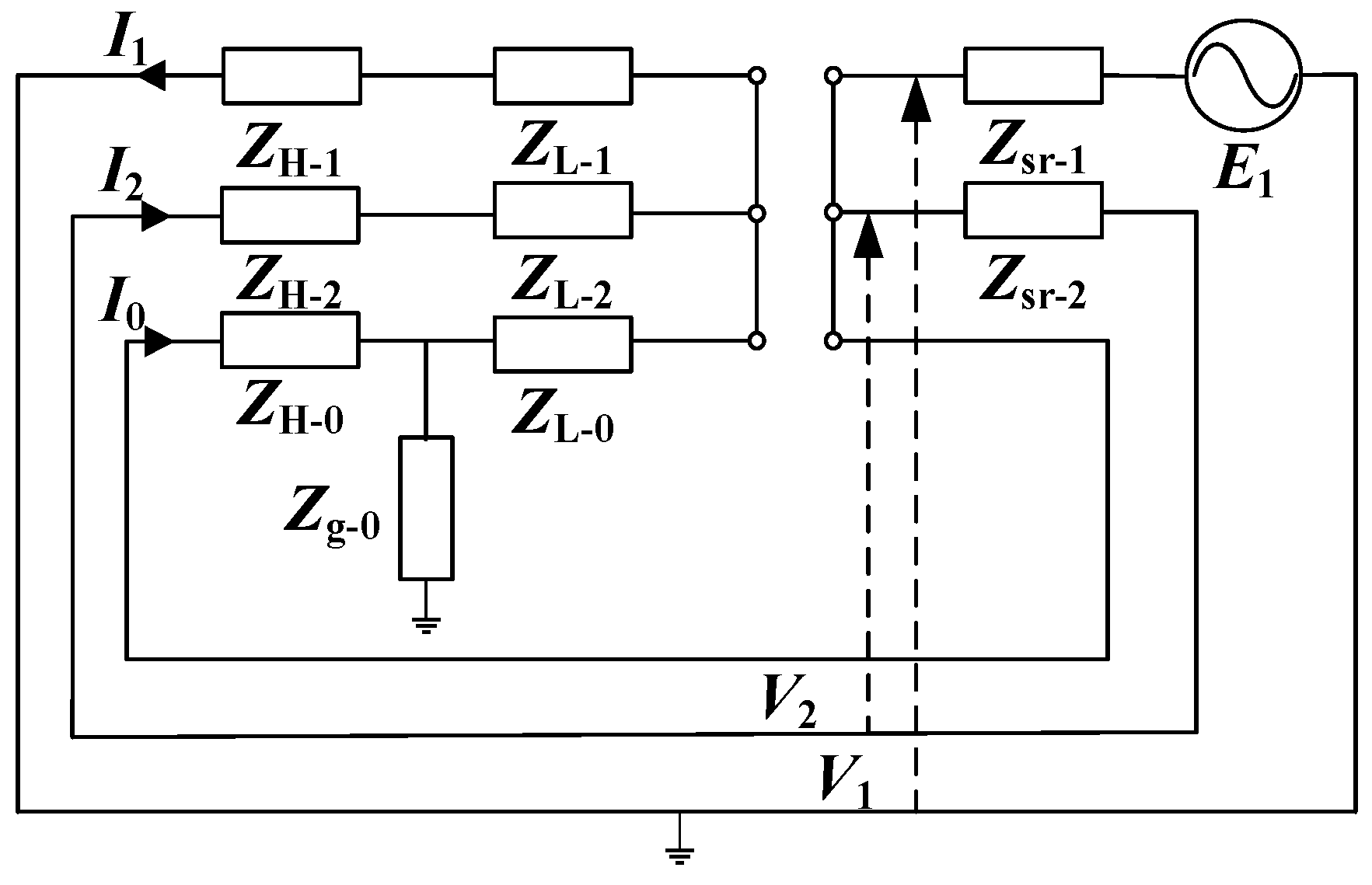
Figure 6.
YNa autotransformer test diagram for the high-voltage side Two-Open-Phase method.
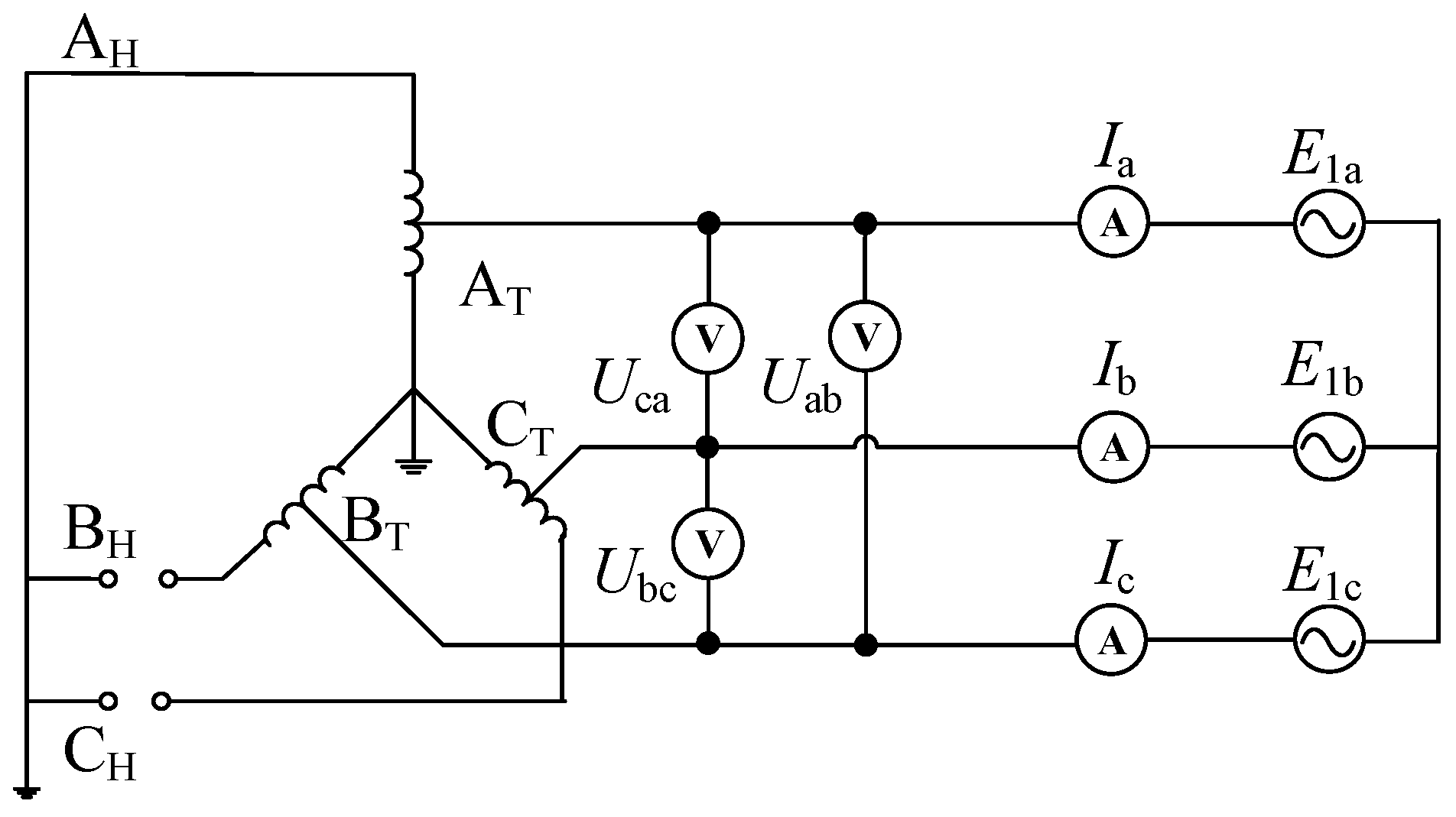
Figure 7.
Sequence network of the YNa autotransformer high-voltage two-Open-Phase test.
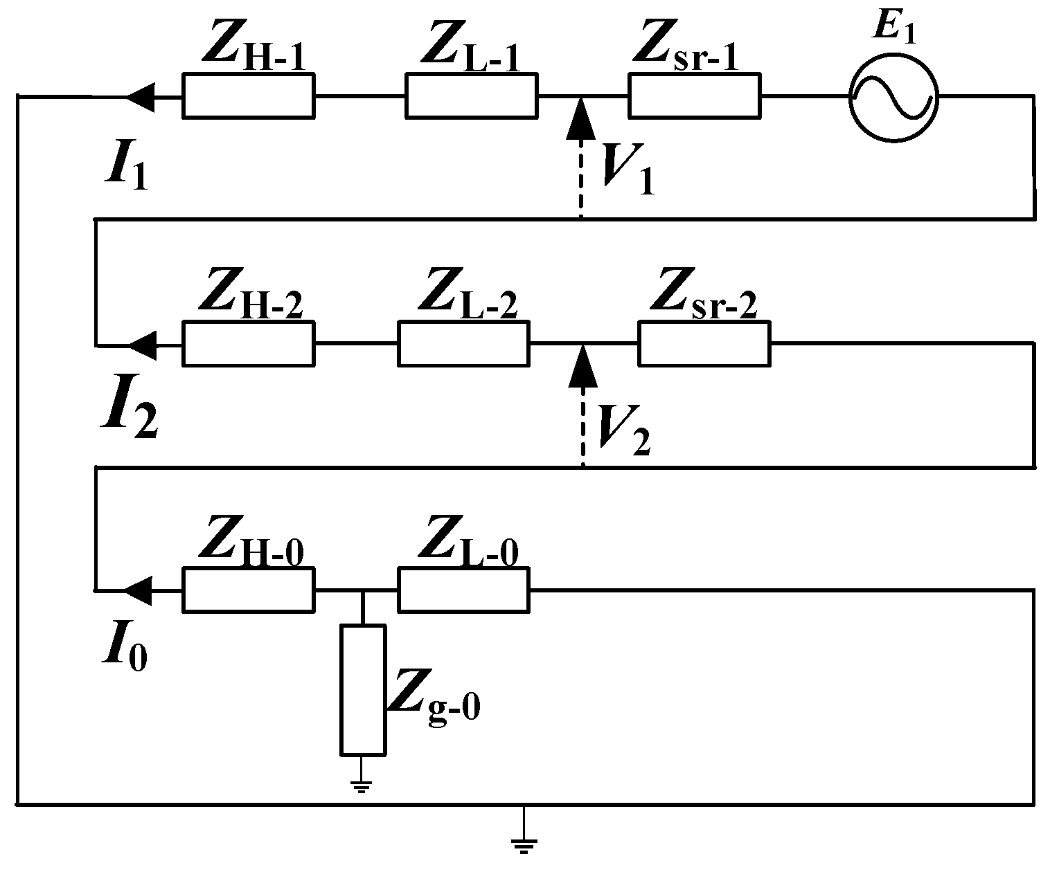
Figure 8.
Phasor diagram of secondary voltage/currents for the low-voltage Two-Open-Phase test. (a) Currents. (b) Voltage.
Figure 8.
Phasor diagram of secondary voltage/currents for the low-voltage Two-Open-Phase test. (a) Currents. (b) Voltage.
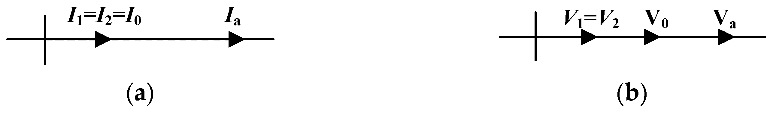
Figure 9.
Test 1 wiring diagram.
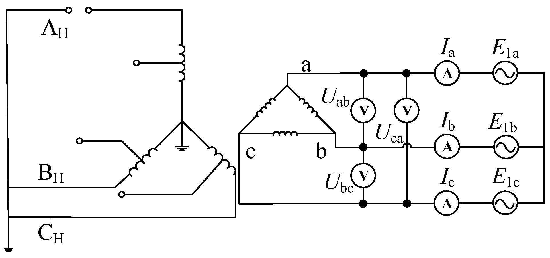
Figure 10.
Sequence network for Test 1.
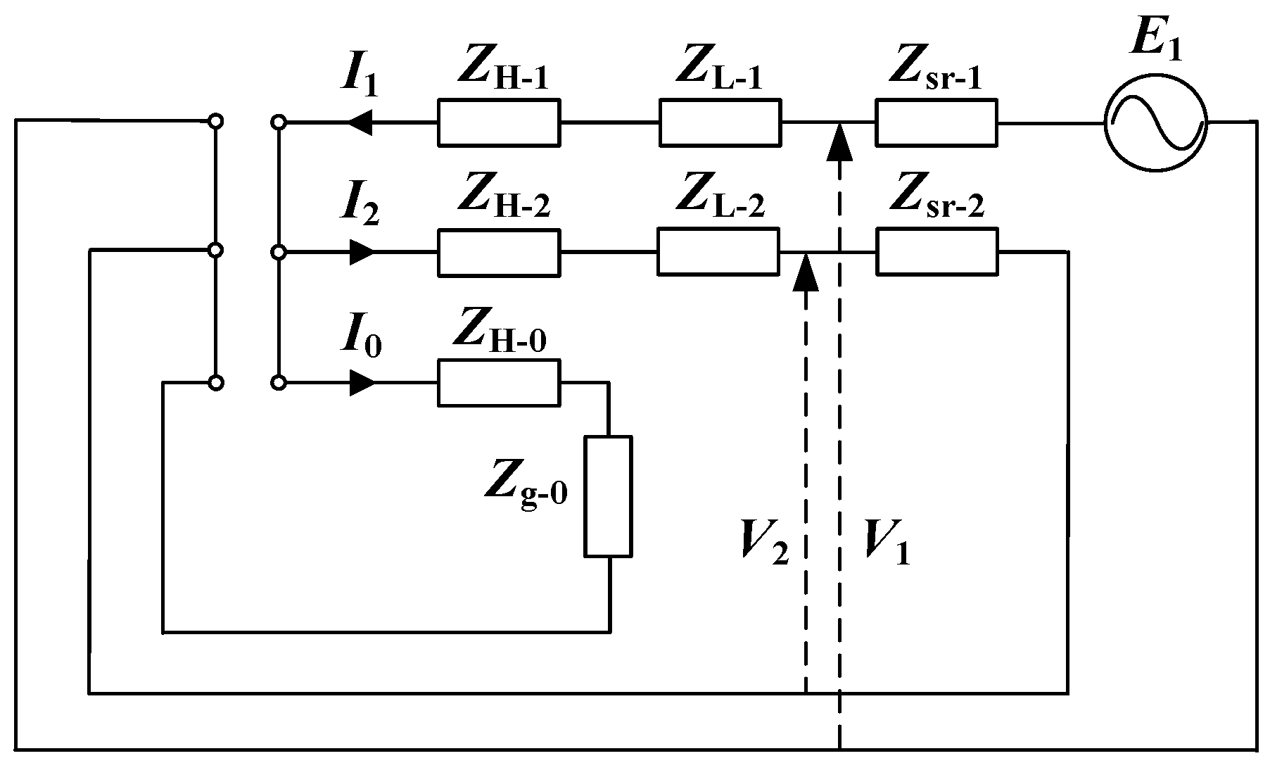
Figure 11.
Phasor diagram of secondary voltage/currents for the high-voltage One-Open-Phase test (a) Currents. (b) Voltage.
Figure 11.
Phasor diagram of secondary voltage/currents for the high-voltage One-Open-Phase test (a) Currents. (b) Voltage.
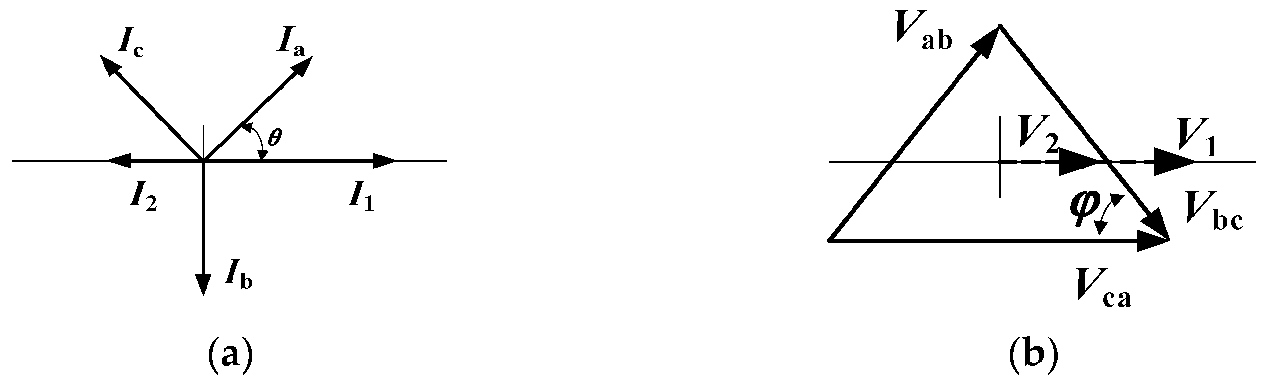
Figure 12.
Test 3 wiring diagram.

Figure 13.
Sequence network for Test 3.

Figure 14.
Test 4 wiring diagram.
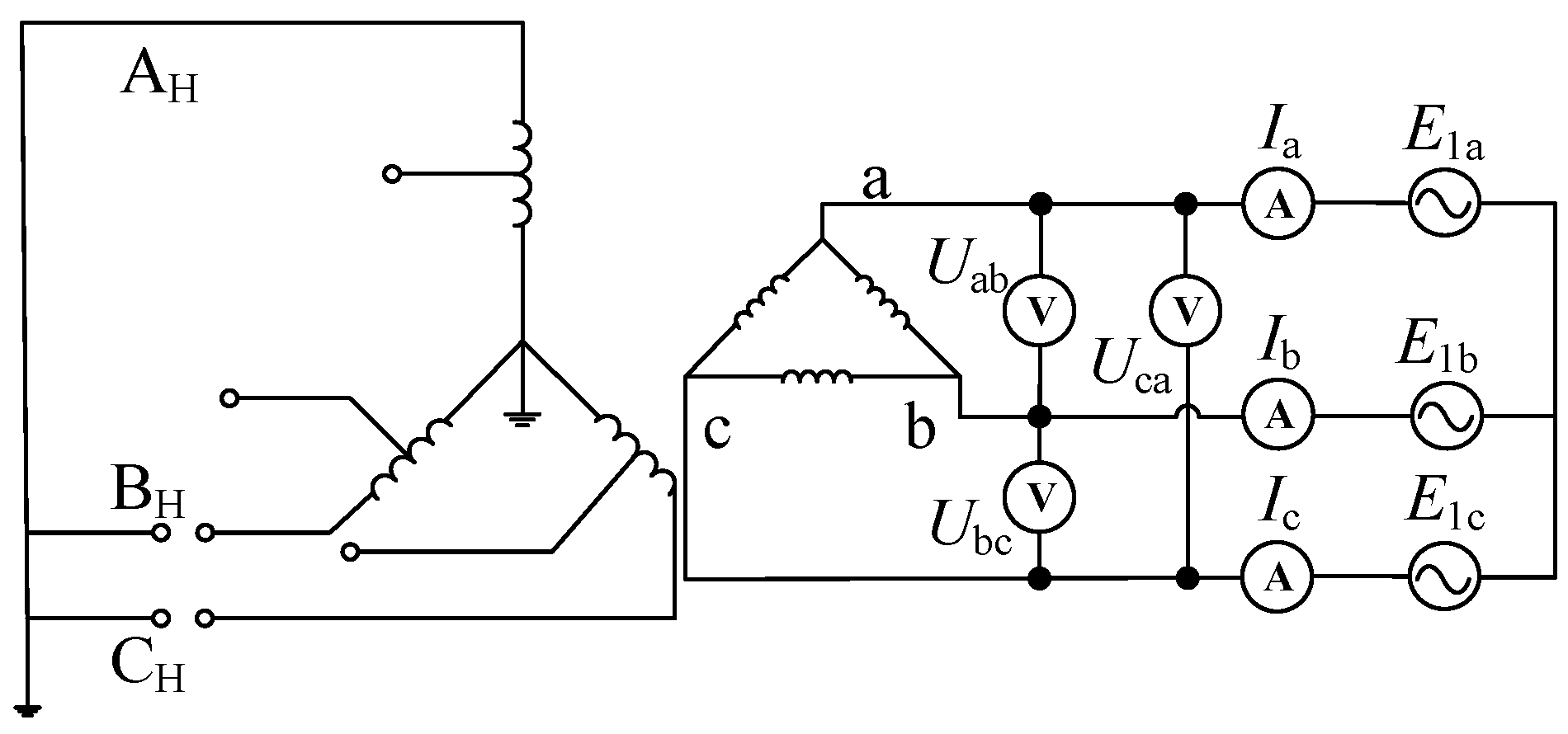
Figure 15.
Sequence network for Test 4.

Figure 16.
Test 6 wiring diagram.
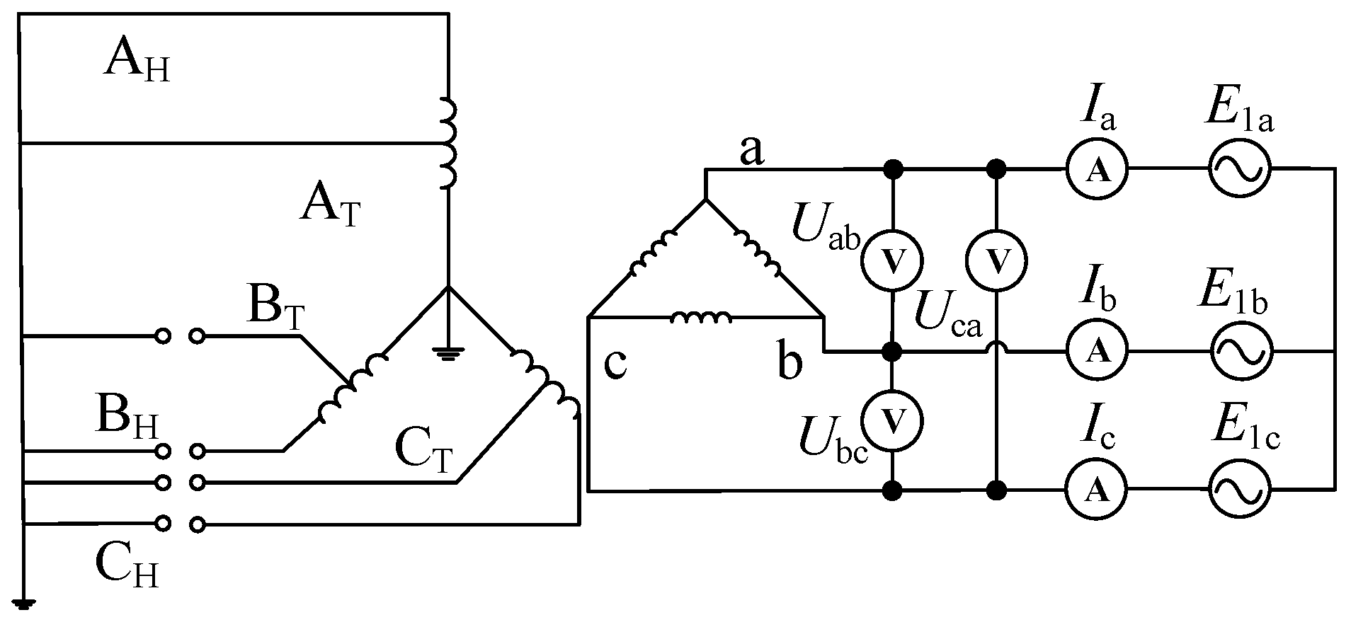
Figure 17.
Sequence network for Test 6.
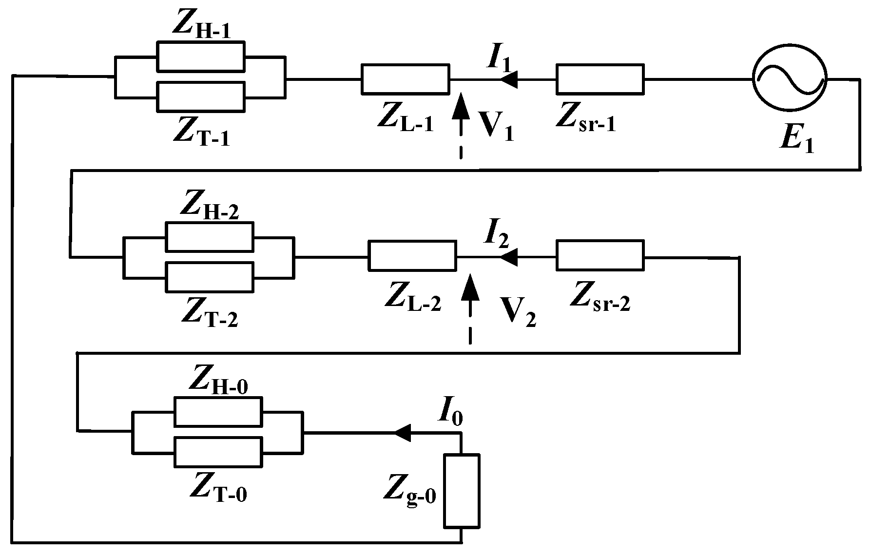
Figure 18.
The measurement process of the zero-sequence impedance.


Table 1.
The comparison between a conventional transformer and an autotransformer.
| Transformer Type | Size | Cost | Applicability |
|---|---|---|---|
| Conventional transformer | Larger | Higher | General load |
| Autotransformer | Smaller | Cheaper | Large-capacity load |
Table 2.
Transformer parameters.
| Capacity/kVA | No-Load Loss/kW | Load Loss/kW | Short Circuit Impedance % | |
|---|---|---|---|---|
| YNa0 autotransformer | 31,500 | 45 | 157 | 13 |
| YNa0d11 autotransformer | 63,000 | 30 | 132 | 9 (High-Medium) 28 (High-Low) 20 (Medium-Low) |
Table 3.
One-phase disconnection test of double-winding autotransformer.
| Standard Test Measured Value | One-Phase Disconnection Test | ||
|---|---|---|---|
| High-Voltage | Low-Voltage | ||
| V0 | 1443 V | - | |
| 3I0 | 33.58 A | - | |
| Vab | - | 379.4 V | 399.8 V |
| Vbc | - | 350.9 V | 414.6 V |
| Vca | - | 385.6 V | 385.1 V |
| Iab | - | 13.51 A | 13.78 A |
| Ibc | - | 22.98 A | 23.65 A |
| Ica | - | 13.88 A | 13.95 A |
| (%) | 9.58 | 9.76 | 9.38 |
| error | - | 1.88% | −2.01% |
Table 4.
Two-phase disconnection test of double-winding autotransformer.
| Standard Test Measured Value | Two-Phase Disconnection Test | ||
|---|---|---|---|
| High-Voltage | Low-Voltage | ||
| V0 | 1443 V | - | - |
| 3I0 | 33.58 A | - | - |
| Vab | - | 358.3 V | 402.7 V |
| Vbc | - | 400 V | 0 V |
| Vca | - | 361.3 V | 390.3 V |
| Ia | - | 17.66 A | 17.64 A |
| Ib | - | 0.522 A | 0 A |
| Ic | - | 0.522 A | 0 A |
| (%) | 9.58 | 9.65 | 9.69 |
| error | - | 0.73% | 1.15% |
Table 5.
One-phase disconnection test on high-voltage side of three-winding autotransformer.
| Standard Test Measured Value | Disconnection Test | |||
|---|---|---|---|---|
| Test 1 | Test 2 | Test 3 | ||
| V0 | 1926 V | - | - | - |
| 3I0 | 449.9 A | - | - | - |
| Vab | - | 316.4 V | 319.3 V | 321.7 V |
| Vbc | - | 315.2 V | 317.1 V | 319.4 V |
| Vca | - | 396.3 V | 396.4 V | 398.2 V |
| Ia | - | 37.5 A | 39.3 A | 41.4 A |
| Ib | - | 42.7 A | 45.2 A | 48.5 A |
| Ic | - | 38.8 A | 38.6 A | 41.8 A |
| (%) | 24.8 | 25.1 | - | - |
| (%) | 16.8 | - | 17.3 | - |
| (%) | 17.2 | - | - | 17.5 |
| Error | - | 1.19% | 2.97% | 1.74% |
Table 6.
Two-phase disconnection test on high-voltage side of three-winding autotransformer.
| Standard Test Measured Value | Disconnection Test | |||
|---|---|---|---|---|
| Test 4 | Test 5 | Test 6 | ||
| V0 | 1926 V | - | ||
| 3I0 | 449.9 A | - | ||
| Vab | - | 384.3 V | 378.4 V | 378.2 V |
| Vbc | - | 400 V | 400 V | 398 V |
| Vca | - | 396.2 V | 394.6 V | 383.5 V |
| Ia | - | 41.7 A | 63.3 A | 68.6 A |
| Ib | - | 0 A | 0 A | 0 A |
| Ic | - | 41.5 A | 63.1 A | 68.6 A |
| (%) | 24.8 | 24.9 | - | - |
| (%) | 16.8 | - | 17.1 | - |
| (%) | 17.2 | - | - | 17.5 |
| Error | - | 0.40% | 1.78% | 1.74% |
Disclaimer/Publisher’s Note: The statements, opinions and data contained in all publications are solely those of the individual author(s) and contributor(s) and not of MDPI and/or the editor(s). MDPI and/or the editor(s) disclaim responsibility for any injury to people or property resulting from any ideas, methods, instructions or products referred to in the content. |
© 2023 by the authors. Licensee MDPI, Basel, Switzerland. This article is an open access article distributed under the terms and conditions of the Creative Commons Attribution (CC BY) license (https://creativecommons.org/licenses/by/4.0/).
Share and Cite
MDPI and ACS Style
Zhang, M.; Fang, J.; Wang, H.; Huang, Q.; Hong, H.; Lin, X.; Zhou, N. Efficient Zero-Sequence Impedance Measurement in Autotransformers Using Low-Voltage Excitation. Appl. Sci. 2024, 14, 215. https://doi.org/10.3390/app14010215
AMA Style
Zhang M, Fang J, Wang H, Huang Q, Hong H, Lin X, Zhou N. Efficient Zero-Sequence Impedance Measurement in Autotransformers Using Low-Voltage Excitation. Applied Sciences. 2024; 14(1):215. https://doi.org/10.3390/app14010215
Chicago/Turabian StyleZhang, Min, Jian Fang, Hongbin Wang, Qingdan Huang, Haicheng Hong, Xiang Lin, and Niancheng Zhou. 2024. "Efficient Zero-Sequence Impedance Measurement in Autotransformers Using Low-Voltage Excitation" Applied Sciences 14, no. 1: 215. https://doi.org/10.3390/app14010215
Note that from the first issue of 2016, this journal uses article numbers instead of page numbers. See further details here.