
Mechanical Characteristics and Damage Constitutive Model of Fiber-Reinforced Cement-Stabilized Soft Clay

1
College of Civil Engineering, Longdong University, Qingyang 745000, China
2
Wuhan Institute of Rock and Soil Mechanics, Chinese Academy of Sciences, Wuhan 430071, China
3
Advanced Modelling, Offshore Energy, Norwegian Geotechnical Institute (NGI), Sognsvn. 72, 0855 Oslo, Norway
*
Authors to whom correspondence should be addressed.
Appl. Sci. 2024, 14(4), 1378; https://doi.org/10.3390/app14041378
Submission received: 18 December 2023
/
Revised: 26 January 2024
/
Accepted: 31 January 2024
/
Published: 8 February 2024
(This article belongs to the Special Issue Mechanical Properties and Engineering Applications of Special Soils)
Abstract
:Marine soft clays are prevalent in coastal regions of China, giving rise to engineering challenges such as salt swelling, corrosion, and load bearing in foundations with soft soil. This study is dedicated to enhancing the mechanical properties of fiber-reinforced cement-stabilized soft clay (FCSSC) and revealing its strengthening mechanism. Uniaxial compression tests are performed to explore the impact of fiber length, fiber amount, and curing ages on mechanical behavior. The stabilization mechanisms of cement and glass fibers are explored through damage analyses and microscopy. Based on the experimental results, a damage constitutive model is formulated for FCSSC, and its validity is established by comparing fitting curves with testing curves. The results demonstrate a significant improvement in the mechanical properties of the stabilized soil, attributed to the synergistic effects of the cement and glass fibers. The growth rate of the unconfined compressive strength decreased with increasing curing ages. Notably, the fiber length significantly impacted the strength index, with short-chopped fibers playing a crucial role in strength enhancement. The compressive strength exhibited an initial increase followed by a decrease with rising fiber content, reaching a maximum between 0.3% and 0.4%. The bridging effect of the glass fibers proved effective in inhibiting compression crack expansion and mitigating structural damage of the soil sample. However, excessive fiber content or length led to improved local porosity, resulting in the deterioration of strength and deformation properties. The stress–strain curves fitted using the proposed damage constitutive model accurately reflected the stress–strain relationship and deformation characteristics of the FCSSC.
1. Introduction
Soft clay is extensively distributed in coastal bays, harbors, and inland salt lakes across China [1]. Sodium chloride (NaCl) in groundwater is acknowledged as a crucial factor contributing to the susceptibility of pavement, slopes, and foundations to failure in coastal regions [2]. Several types of soils either incorporate chloride ions in their chemical compositions or are influenced by NaCl due to their proximity to seawater sources. Within the expanse of the Port of Tianjin, the soft clay exhibits distinctive characteristics, including a high liquid limit, significant void ratio, elevated natural moisture content, low natural gravity, and diminished strength attributed to the hydrogeologic conditions [3,4,5]. These inherent properties render it unsuitable for direct utilization in engineering applications. The degradation of engineering properties leads to uneven deformation, cracking, and dissolution, necessitating the modification and treatment of soft clay for construction engineering [6].
The rapid development of infrastructure construction along the coastal areas of China has stimulated the development of major engineering projects, including high-speed railways, highways, airports, and nuclear power stations, all situated on soft clay terrain [7]. Consequently, the modification of soft clay has emerged as a pressing and crucial concern in geotechnical engineering. Presently, the widely adopted method for treating weak or problematic soils involves chemical curing, employing agents such as cement, lime, and other gelling agents. Utilizing cement as the curing agent, a profound mixture of soft clay and the curing agent can be achieved through techniques like grouting, anchoring, and mixed piling, among others [8]. In the context of pile foundations, this process transforms the soft clay into a robust pile characterized by integrity, water stability, and impressive bearing strength, facilitated by a series of physical and chemical reactions. Cemental soils significantly enhance the compressive strength of soft clay, mitigating the risk of excessive foundation settlement [9]. However, relying solely on traditional Portland cement as the curing agent to achieve a mixing pile that meets load bearing requirements presents practical challenges. Environmental factors and external loads can contribute to strength deterioration, cracking, and deformation in cement mixing piles, thereby posing risks to construction projects [10]. Therefore, there is an urgent imperative to develop high-performance stabilized soft clay capable of ensuring the stability of slopes and foundations [11,12].
The mechanical properties of soft clay wield significant influence on the load bearing capacity of cement mixing piles in geotechnical engineering. Critical elements such as the dosages of the gelling agent, material components, and admixtures all contribute substantially to its curing effectiveness [13,14,15]. Recent research endeavors have honed in on augmenting the strength of stabilized soil by incorporating various types and quantities of natural and artificial fibers [16,17]. With advancements in solid waste recycling, experiments have been undertaken to enhance the applicability of glass waste [18]. In practical applications, the incorporation of glass fibers in cement-based materials has exhibited promising outcomes. He et al. [19] delved into the influence of glass fibers on the mechanical behavior and microscopic morphology of filling slurry, highlighting the pronounced influence of fiber content on compressive and flexure strength. Via performing pullout tests and shear tests, Shi et al. [20] observed a significant improvement in the tensile strength of soft soil reinforced by glass fibers. Wang et al. [21] introduced high-titanium glass fibers into stabilized soft clay, revealing marked variations in fluidity, compressive strength, elastic modulus, and other physical parameters based on the fiber content. Schneider et al. [22] conducted mechanical experiments to scrutinize the reinforcement rules of glass fibers in cemental materials, delving into the reinforcement mechanism through microscopy. Collectively, soil reinforcement with glass fibers efficaciously elevates the bonding degree of stabilized soft clay, enhances mortar’s interfacial adhesion, inhibits crack expansion, and maximizes the improvement in load bearing capacity [23]. However, the factors governing the strength of cemental soft clay with fiber reinforcement have not been comprehensively examined, underscoring the need to enrich the research in this regard.
In this study, uniaxial compression tests were conducted on fiber-reinforced cement-stabilized soft clay (FCSSC) to examine the changing patterns in its mechanical properties under different curing ages, lengths, and amounts of glass fibers. Microscopic image analysis was employed to unveil the glass fiber mechanism and identify the optimal content. Furthermore, we have established a damage constitutive model for specimens of FCSSC, verifying its accuracy and validity. The findings of this research offer theoretical and technical guidance for constructing infrastructure on grounds of marine soft clay.
2. Materials and Methods
Figure 1 presents an overview of the raw materials used and the testing procedure followed in this study. The materials employed for sample preparation, encompassing soft clay, cement, fly ash, and glass fibers, are presented in Figure 1a. The machine employed for mixing the materials is presented in Figure 1b, and a real photo of the cured soil sample is shown in Figure 1c.
2.1. Testing Materials
2.1.1. Soft Clay
The experimental soft clay was sourced from a subgrade located in the coastal area of Zhuhai, Guangdong Province, China. The sampling site, situated in a coastal delta region, features a complex topography and abundant groundwater resources. Natural samples of soft clay were collected automatically using a medium-sized core drill. Based on basic ASTM standards, physical, strength, and mineralogical tests were conducted to characterize the physical properties of the material, the detailed results of which are provided in Table 1. The X-ray diffraction test, conducted following ASTM D4926-15 (2015) [24], indicated that the claystone consists of non-clay minerals including quartz (33.1%), feldspar (7.5%), chlorite (4.4%), and clay minerals including montmorillonite (12.9%) and kaolinite (42.1%). Following the ASTM standards (D4318-17e1, ASTM D6938-17ae1) [25,26], Table 1 details the physical properties of the soft clay, revealing characteristics such as its high natural water content, high compressibility, low load bearing capacity, and low permeability. The soft clay we collected falls within the category of a saturated cohesive soil based on its liquid limit value, transitioning between a soft plastic and fluid plastic state. Figure 2 depicts the particle size distribution of the soft clay, characterized by smaller particles, classifying it as a low-grade soil. The chemical composition results of the soft clay, detailed in Table 2, highlight that SiO2 and Al2O3 are its dominant elements. The results of the mineral phase analysis indicate quartz to be the primary mineral phase in the soil, with sheet-like muscovite being the secondary mineral phase.
2.1.2. Gelling Agent
The gelling agent employed for soil stabilization consists of cement and fly ash. The sulfoaluminate cement utilized here primarily comprises dicalcium silicate and anhydrous calcium sulfoaluminate as its main mineral components. The specific surface area of the cement particles is 349.5 m2/kg, and it exhibits a final setting time of 90 min, which is considerably lower than conventional Portland cement, making it an exceptionally efficient gelling agent. The fly ash utilized herein was obtained from coal-fired power plants, with its particle specific surface area measuring 350 g/cmg. The dry density of the fly ash was recorded at 1.79 g/cm3.
2.1.3. Glass Fibers
Technical indicators related to the glass fibers employed herein are listed in Table 3. The fibers exhibit high ductility, excellent mechanical properties, strong corrosion resistance, and non-toxicity, which is conducive to environmental protection.
2.2. Experimental Method and Design Ratio
Table 4 depicts the fundamental mix ratio of the stabilized soft clay. According to our preliminary experiments, the proportions of water, fly ash, cement, and clay in the research mixture were determined to be 22.5%, 3%, 12%, and 62.5%, respectively. The glass fibers were introduced through dry mixing. Initially, the weighed soft clay, fly ash, and cement were placed into the planetary mixer. Subsequently, glass fibers were added to the blender in batches, subjected to dry mixing for 120 s, followed by blending with water and stirring for 5 min. Subsequently, the mixture was transferred to the mold and compacted using the static compaction method, which has been widely employed for fine-grained soils. Finally, the mold was removed after the samples had reached a given curing time. Figure 1c illustrates the solidified samples of cement soil and fibers after pouring and curing, with the cylindrical samples having a diameter and length of 50 mm and 100 mm, respectively.
To determine the optimal ratio for fiber-reinforced cemental soil, tests were conducted with three different fiber lengths and six different amounts of glass fibers. Mechanical tests were employed to ascertain the unconfined compressive strength (UCS) of the samples. Based on preliminary experiments, the proportions of water, fly ash, cement, and clay in the research mixture were determined to be 22.5%, 3%, 12%, and 62.5%, respectively. Furthermore, the fiber length was set at 5, 10, and 15 mm, denoted as short-cut, medium-cut, and long-cut fibers, respectively. We prepared stabilized soft clay samples with five different fiber contents, corresponding to dry masses of 0.1%, 0.2%, 0.3%, 0.4%, and 0.5% of the total sample mass, respectively. The level design of the 16 groups of factors under investigation is meticulously outlined in Table 5, with F0 serving as the reference group.
2.3. Testing Method
2.3.1. Unconfined Compressive Tests
The optimum water content was used for the test samples. Before performing a unconfined compressive test (UST), compaction tests were carried out on the cemented soft clays to obtain the maximum dry density and optimum water content. The compaction tests were conducted following the ASTM D698-12(2021) standard [27]. Subsamples with specified moisture contents were placed in three layers into a 101.6 mm diameter mold. Each layer was compacted with 25 blows from a 24.5 Newton ram dropped from a height of 305 mm. The compaction test was repeated five times to establish the compaction curve, determining the optimum moisture content and maximum dry density of the samples. Then, the tested samples were prepared under optimal water content conditions. UST experiments were executed using a uniaxial compression testing machine, with the loading rate set to 0.25 mm/min. Preloading was implemented before initiating the test to eliminate the gap between the bearing plate and the sample. The preloading force was set at 0.01 kN. Following sample failure, a high-definition camera was employed to capture images for analyzing the failure mode under compressive loading.
2.3.2. Scanning Electron Microscopy
The microstructure and morphology of the sample were examined using the results of scanning electron microscopy (SEM) tests. Prior to the experiment, a thin sheet sample measuring 5 mm × 5 mm × 2 mm was extracted from the center of the test block and immersed in absolute ethanol for 24 h. Subsequently, the sample underwent slicing and gold plating, and then morphologic observation under an SEM for measurement.
3. Results
3.1. Stress–Strain Curves
A uniaxial compression test was conducted on the fiber-reinforced cement-stabilized soft clay, with the sample dimensions measuring 50 mm in diameter and 100 mm in height, and with a compression rate of 0.25 mm/min. The stress–strain relationships and fracture morphology under different fiber content conditions were experimentally acquired. As depicted in Figure 3, the sample exhibited three stages of initial compaction with the increase in vertical strain, including elastic rise, post-peak stress drop, and residual distortion. Utilizing glass fibers resulted in an increase in the peak stress and a corresponding vertical strain increase. This suggests that fiber reinforcement enhances the plastic deformation of the sample compared to ordinary cemental soil and other solidified materials. In addition, introducing an appropriate amount fibers improves the strength and ductility of the materials.
Compression failure realized mainly through three gradual stages, corresponding to the changes in the stress–strain curve. Figure 4 illustrates the morphology of the damaged sample observed through the uniaxial compression test. Figure 4a depicts the initial compression stage, where the native porosity within the sample is reduced. The vertical stress gradually rises with increasing strain, and small oblique cracks appear, accompanied by a few bumps on the surface. Figure 4b demonstrates the progression of damage as the sample undergoes plastic deformation, leading to a rapid increase in vertical stress with rising strain. Compression-induced cracks propagate towards the edge, resulting in oblique failure cracks, accompanied by a limited number of particles falling off the sample surface. In addition, Figure 4c displays the morphology of the sample in the fracturing stage. It is evident that as the vertical stress continues to increase, the compression cracks induced in the middle of the sample expand, and numerous articles progressively detach. In this stage, the vertical stress drops rapidly, leading to severe brittle failure of the FCSSC sample.
3.2. Effect of Curing Time, Fiber Length, and Fiber Amount on Strength
The stress–strain curves for the specimens of FCSSC were obtained from the UCT results, encompassing conditions of varying fiber lengths and amounts. The pinnacle stress, indicative of the unconfined compressive strength, was extracted from these curves to quantify the static properties of the sample. These results are visually represented in Figure 5. Specifically, Figure 5a–c illustrate the significant impact of curing time, fiber content, and fiber length on the results of compressive strength testing. Table 6 presents a comprehensive overview of the uniaxial compression test results and the percentage growth in unconfined compressive strength. With the extension of curing time, there is a continuous increase in compressive strength observed across diverse groups of the FCSSC samples. The growth rate of the strength exhibits a higher value within the initial 1–7 days of curing, eventually stabilizing during the subsequent 7–14 days. In summary, the compressive strength of the cured samples demonstrates a higher magnitude in the early stages, reaching a peak at a curing age of 7 days. This experimental observation aligns with previous studies focusing on cement-based fiber-modified materials.
Under varying curing ages, the strength of FCSSC exhibits an initial increase followed by a decline with the rise in fiber content. The pivotal point for changes in the compressive strength of these specimens of FCSSC is found at amounts in the range of 0.3–0.4%. Notably, the length of the fibers plays a crucial role in influencing compressive strength, with short-cut fibers providing the most effective reinforcement. This effectiveness is attributed to the glass fiber monofilaments with a length of 5 mm (short-cut fibers) possessing the largest ratio of length to diameter. This characteristic ensures optimal contact with the hydration gel product and provides the ability to withstand greater compressive stress. The destruction of the sample is accompanied by the transfer and conversion of energy, and the emergence of failure cracks results from the accumulation and subsequent release of surface energy. The severity of fracturing damage correlates with the higher surface energy generated during compression failure. In samples without a fiber addition, cracks persistently expand under the load, concurrently enlarging the fracturing damage zone. As the fiber content increases, the intensity of compression damage to the FCSSC sample diminishes. However, excessive fiber length tends to counteract this, leading to poor deformation resistance in specific areas, consequently impacting the reinforcing effect.
The reinforcing effect of the fibers on the stabilized soft clay experiences an initial ascent followed by a decline with increases in fiber content, indicating that an excessive addition of fibers may yield diminishing returns. In comparison to the UCS values of the reference group, the maximum increase in compressive strength for the short-cut, medium-cut, and long-cut fiber-reinforced samples was achieved at fiber contents between 0.3% and 0.4%, showing values of 88.3%, 70.9%, and 77.1%, respectively. The addition of fibers promotes the formation of a three-dimensional network within the sample, amplifying adhesion and mechanical interlocking forces between the sand particles and hydration products, contributing to improving the load bearing capacity. Notably, at low fiber contents, the friction and cohesion between the fibers and clay grains are minimal, allowing for relatively easy sliding of the cemented particles. Furthermore, long fibers do not consistently arrest crack development, resulting in structured material damage. As the fiber content increases, the contact zones between the fibers and cemented particles expand, increasing the interfacial friction. Simultaneously, the fibers create intersections and form a connecting network, enhancing spatial confinement in the samples. Consequently, the unconfined compressive strength of fiber-reinforced cemental soil specimens gradually increases until it reaches a peak. However, excessive contents or lengths of glass fibers results in fiber interconnection, increasing the local porosity of the stabilized soft clay and reducing its ability to resist deformation under external loading.
3.3. Microscopic Characteristics of Fiber-Reinforced Cement-Stabilized Soft Clay
To elucidate the strengthening mechanism, SEM analyses were conducted on the samples of FCSSC with a curing age of 7 days, a fiber content of 0.3%, and a fiber length of 5 mm. Meanwhile, the morphology of both the intact and damaged samples after uniaxial compression was observed and compared using microscopic scanning. Previous studies have indicated that the active components in cement and fly ash, such as calcium silicate minerals, react with clay during the curing process, leading to the formation of cementitious products [1,7,8]. This reaction enhances the strength and stability of the soil. As depicted in Figure 6a, before failure, the stabilized soft clay contains C-S-H gel and Ca(OH)2, with clay particles tightly wrapped, covered, and bonded by numerous hydrates, thereby enhancing the density of the stabilized soft clay. In Figure 6b, the hydration gel substance adheres to the fiber’s surface, causing an overlap between the fibers and the hydration product, thereby improving the bonding force and mechanical interlocking force in the cement mortar. Simultaneously, the curing agent may reduce the water absorption of fibers and slow down the decay or degradation process of fibers, thereby enhancing the durability of fiber-rich soils. Figure 6c reveals the microscopic morphology of the fractured cement mortar sand. Notably, the fibers exhibited no breakage post sample failure but underwent pulling, suggesting fiber displacement or rotation. This signifies that the fibers possess high tensile strength and act as a bridge among the clay–cement particles inside the specimens of FCSSC. This inhibits the expansion of compression cracks, thus allowing cracks to expand on both sides of the fibers. Consequently, the overall severity of deformation and compression fracture is reduced in the sample. Regarding the mechanism of action, after reaching the peak compressive strength of the specimens of FCSSC, exceeding the optimal fiber content and length leads to overlapping and entanglement, causing non-uniform dispersion in the soil. This may result in weak interfaces, reducing the adhesive strength of the fibers and hydration products. Thus, glass fiber-reinforced cement-stabilized soft clay must contain an optimum combination of fiber content and length.
4. Damage Constitutive Model
After decades of development, damage constitutive models for rock and soil under loading have been formulated by combining elastic and viscoplastic mesoscopic damage during deformation [28]. Particularly, the random distribution of micro-cracks in the specimen and the evolutionary damage in later stages are correlated with the initial damage [29]. Therefore, it is assumed herein that the axial strain of the specimen satisfies the following Equation (1) [30]:
where m and F are fitting constants, ε refers to the axial strain, and P(ε) denotes the distribution function of probability.
As demonstrated in Figure 7, if ND is designed to represent the number of microelements that have been destroyed inside a damaged specimen under a certain level of loading, the total number of microelements inside the specimen is signified by NT, and the their ratio can be defined as the damage variable D, as follows [30]:
The number of destroyed microelements Nt in the specimen is defined as follows:
The damage variable can be expressed by the following Equation (4).
According to the principle of effective stress, the axial stress σ is defined as Equation (5):
where is the effective stress, and E is elastic modulus.
The mechanical constitutive model plays a pivotal role in comprehending the mechanical behavior of reactive materials. Given that the stress–strain curves of stabilized soft clay exhibit linear rises and strain softening as their two most prominent features, a piecewise constitutive model based on mesoscopic damage mechanics is employed to accurately fit and address these curves. Drawing from previous research [31], the constitutive model equation is represented by Equation (6). The fitting parameters a and b of the constitutive model are determined by analyzing the specific UCS experimental data for five different fiber contents in the 5 mm short-fiber group using Equation (6), and these results are presented in Table 5. The correlation coefficient R2 predicted by the constitutive model exceeds 0.95. These fitting outcomes affirm that the aforementioned constitutive equation adeptly captures the stress–strain relationship of stabilized soft clay samples.
where su is the peak stress, and εu represents the strain at the peak point.
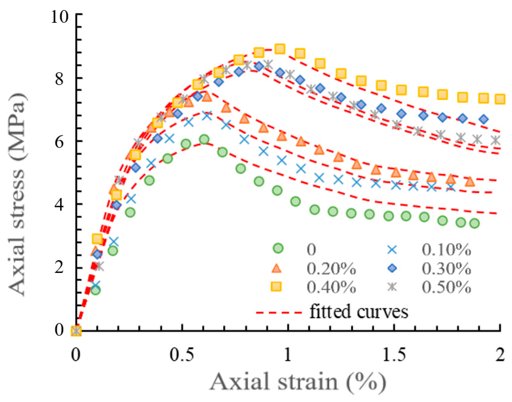
The fitting parameters a and b in the proposed constitutive model carry specific physical significance [32]. Specifically, a in the rising section of the stress–strain curves reflects the ratio of the initial elastic modulus to the peak modulus of the materials, providing insights into the ductility characteristics of the materials. On the other hand, b in the descending section of the curves reveals the brittleness of the materials. As indicated in Table 6, with the increase in fiber content, a exhibits an upward trend, signifying an improved ductility of the fiber-reinforced cement-stabilized soil, which aligns with the test results. Simultaneously, b demonstrates a decrease followed by an increase, with the final value being lower than that of cement soil without fibers. This suggests that the brittleness damage degree of the materials becomes weaker after fiber modification [33,34]. Figure 8 compares the predicted results of the constitutive model and the measured results. It is evident that the stress of the samples follows a roughly complex linear elastic change law before reaching the peak value, while a structural fracture surface appears and the stress decreases after reaching the peak value [35,36]. In addition, Figure 8 illustrates highly similar shapes and geometric features between the measured curves and the predicted curves. Therefore, the constitutive model proposed in this research can reasonably and accurately reflect the mechanical behavior of specimens of FCSSC.
5. Conclusions
In this investigation, glass fibers are utilized to reinforce and modify cement-stabilized soft clay. A comprehensive exploration of the mechanical strength is conducted through a uniaxial compression test, scrutinizing the influence of fiber length, fiber amount, and curing time on mechanical strength. Additionally, the mechanism of fiber reinforcement of FCSSC is analyzed based on microscopic images. The following conclusions have thus been drawn.
- (1)
- The utilization of glass fibers enhances the performance of FCSSC in plastic deformation and compressive strength. At a curing age of 7 days, the stabilized soft clay demonstrates heightened compressive strength, contributing to an improved early strength profile.
- (2)
- The length of the glass fibers in FCSSC plays a pivotal role in determining the unconfined compressive strength of stabilized soft clay. The reinforcing effect is most pronounced for short-cut fibers, followed by medium-cut fibers and long-cut fibers. This is attributed to the intimate contact of shorter-chopped fibers with the hydration gel, enabling the sample to withstand greater compressive stress.
- (3)
- The impact of increasing the fiber content on the strength index follows an initial increase and subsequently decreases. Considering both mechanical properties and engineering economy, the optimal amount is determined to be 0.3%. Excessive fiber content and excessively long fibers may result in cross-linking and entanglement, increasing porosity in the fiber aggregation area and diminishing the sample’s ability to resist loading and deformation.
- (4)
- Glass fibers function as a bridge in stabilized soft clay, effectively inhibiting the expansion of compression cracks and the formation of additional cracks. This action mitigates the overall severity of deformation and compression fractures in the sample. The synergistic interplay between glass fibers and hydration gel constitutes a significant factor involved in enhancing the mechanical properties of stabilized soft clay.
- (5)
- The proposed constitutive model based on mesoscopic damage mechanics proves effective in describing the strain evolution of stabilized soft clay and accurately reflects the softening characteristics observed in the stress–strain curves under uniaxial compression.
Author Contributions
Conceptualization, T.Y.; methodology, T.Y. and S.C.; formal analysis, S.C.; validation, X.Z. (Xingyuan Zhang); investigation, X.Z. (Xingyuan Zhang); resources, X.Z. (Xianwei Zhang); writing—original draft preparation, T.Y.; writing—review and editing, T.Y. and R.A.; supervision, Z.Z. and X.Z. (Xianwei Zhang); funding acquisition, T.Y. All authors have read and agreed to the published version of the manuscript.
Funding
This research was funded by the Qingyang City Science and Technology Talent Special Plan Project (QY-STK-2022A-002); and the 2023 University Teacher Innovation Fund Project (2023A-145).
Institutional Review Board Statement
Not applicable.
Informed Consent Statement
Not applicable.
Data Availability Statement
The data presented in this study are available on request from the corresponding author. The data are not publicly available due to reasonable request.
Acknowledgments
This study was supported by the Qingyang City Science and Technology Talent Special Plan Project (QY-STK-2022A-002) and the 2023 University Teacher Innovation Fund Project (2023A-145). The authors also thank the anonymous reviewers for their comments on this manuscript.
Conflicts of Interest
The authors declare no conflicts of interest.
References
- Rajasekaran, G. Sulphate attack and ettringite formation in the lime and cement stabilized marine clays. Ocean Eng. 2005, 32, 1133–1159. [Google Scholar] [CrossRef]
- Xu, G.; Liu, J.; Liu, S.F.; Wang, Z.B.; Hu, G.; Kong, X.H. Modern muddy deposit along the Zhejiang coast in the East China Sea: Response to large-scale human projects. Cont. Shelf Res. 2016, 130, 68–78. [Google Scholar] [CrossRef]
- Xiao, Z.; Yu, N.; An, J.; Zou, H.; Zhang, Y. Soil compressibility and resilience based on uniaxial compression loading test in response to soil water suction and soil organic matter content in northeast China. Sustainability 2022, 14, 2620. [Google Scholar] [CrossRef]
- An, R.; Wang, Y.X.; Zhang, X.; Chen, C.; Liu, X.; Cai, S. Quantitative characterization of drying-induced cracks and permeabilityof granite residual soil using micron-sized x-ray computed tomography. Sci. Total Environ. 2023, 876, 163213. [Google Scholar] [CrossRef] [PubMed]
- Zhou, J.; Tang, Y. Practical model of deformation prediction in soft clay after artificial ground freezing under subway low-level cyclic loading. Tunn. Undergr. Space Technol. 2018, 76, 30–42. [Google Scholar] [CrossRef]
- Tang, Y.Q.; Zhou, J.; Zhang, M.D.; Liu, Y.D. Research on the thermal conductivity and moisture migration characteristics of Shanghai saline soil. I: Experimental modeling. Bull. Eng. Geol. Environ. 2015, 74, 577–593. [Google Scholar] [CrossRef]
- Zhu, J.F.; Tao, Y.L.; Xu, R.Q.; Yang, H.; Pan, B.J. Investigation on the optimal formulation and mechanism of marine organic silt improved with magnesium-cement-based stabilizer. Constr. Build. Mater. 2022, 341, 127233. [Google Scholar] [CrossRef]
- Yaghoubi, M.; Arulrajah, A.; Disfani, M.M.; Horpibulsuk, S.; Myint, W.B.; Stephen, D. Effects of industrial by-product based geopolymers on the strength development of a soft soil. Soils Found. 2018, 58, 716–728. [Google Scholar] [CrossRef]
- Song, Y.; Cao, J.; Ding, W.; Song, Z.; Liu, H.; Huang, S.; Zhu, W. Influence of Peat Soil Environment on Mechanical Properties of Cement-Soil and Its Mechanism. Sustainability 2023, 15, 4580. [Google Scholar] [CrossRef]
- Pheng, L.S.; Chuan, Q.T. Environmental factors and work performance of project managers in the construction industry. Int. J. Proj. Manag. 2006, 24, 24–37. [Google Scholar] [CrossRef]
- Hu, J.F.; Chen, H.Q.; Zhang, Z.B. Mechanical properties of melamine formaldehyde microcapsules for self-healing materials. Mater. Chem. Phys. 2009, 118, 63–70. [Google Scholar] [CrossRef]
- Savvilotidou, M.; Vassilopoulos, A.P.; Frigione, M.; Keller, T. Effects of aging in dry environment on physical and mechanical properties of a cold-curing structural epoxy adhesive for bridge construction. Constr. Build. Mater. 2017, 140, 552–561. [Google Scholar] [CrossRef]
- Zhang, Y.; Luo, H.; Chen, P.; Liu, E.; Chen, Y. Mechanical Properties and Binary-Medium-Based Constitutive Model for Coral-Reef Limestone Samples Subjected to Uniaxial Loading. Sustainability 2022, 14, 12193. [Google Scholar] [CrossRef]
- Somani, M.V.; Khandelwal, M.; Punia, V.; Sharma, V. The effect of incorporating various reinforcement materials on flexural strength and impact strength of polymethylmethacrylate: A meta-analysis. J. Indian Prosthodont. Soc. 2019, 19, 101. [Google Scholar] [CrossRef] [PubMed]
- Tang, Y.Q.; Yan, J.J. Effect of freeze–thaw on hydraulic conductivity and microstructure of soft soil in Shanghai area. Environ. Earth Sci. 2015, 73, 7679–7690. [Google Scholar] [CrossRef]
- Wille, K.; Naaman, A.E.; El-Tawil, S.; Gustavo, J. Ultra-high performance concrete and fiber reinforced concrete: Achieving strength and ductility without heat curing. Mater. Struct. 2012, 45, 309–324. [Google Scholar] [CrossRef]
- Shi, X.Z.; Zhang, C.; Zhou, X.D. The statistical damage constitutive model of the mechanical properties of Alkali-resistant glass fiber reinforced concrete. Symmetry 2020, 12, 1139. [Google Scholar] [CrossRef]
- Wang, D.H.; Ju, Y.Z.; Shen, H.; Xu, L.B. Mechanical properties of high performance concrete reinforced with basalt fiber and polypropylene fiber. Constr. Build. Mater. 2019, 197, 464–473. [Google Scholar] [CrossRef]
- Schneider, K.; Lieboldt, M.; Liebscher, M.; Fröhlich, M.; Hempel, S.; Butler, M.; Schröfl, C.; Mechtcherine, V. Mineral-based coating of plasma-treated carbon fiber rovings for carbon concrete composites with enhanced mechanical performance. Materials 2017, 10, 360. [Google Scholar] [CrossRef] [PubMed]
- He, G.S.; Li, J.; Zhang, F.S.; Wang, C.; Guo, S.Y. Effect of multistage tensile extrusion induced fiber orientation on fracture characteristics of high density polyethylene/short glass fiber composites. Compos. Sci. Technol. 2014, 100, 1–9. [Google Scholar] [CrossRef]
- Liu, J.; Xie, X.; Li, L. Experimental study on mechanical properties and durability of grafted nano-SiO2 modified rice straw fiber reinforced concrete. Constr. Build. Mater. 2022, 347, 128575. [Google Scholar] [CrossRef]
- Wu, Z.M.; Khayat, K.H.; Shi, C.J. Effect of nano-SiO2 particles and curing time on development of fiber-matrix bond properties and microstructure of ultra-high strength concrete. Cem. Concr. Res. 2017, 95, 247–256. [Google Scholar] [CrossRef]
- Sun, J.F.; Zhao, F.; Yao, Y.; Jin, Z.; Liu, X.; Huang, Y.D. High efficient and continuous surface modification of carbon fibers with improved tensile strength and interfacial adhesion. Appl. Surf. Sci. 2017, 412, 424–435. [Google Scholar] [CrossRef]
- ASTM D4926-15; Standard Test Method for Gamma Alumina Content in Catalysts and Catalyst Carriers Containing Silica and Alumina by X-Ray Powder Diffraction. ASTM: West Conshohocken, PA, USA, 2015.
- ASTM D4318-17e1; Standard Test Methods for Liquid Limit, Plastic Limit, and Plasticity Index of Soils. ASTM: West Conshohocken, PA, USA, 2017.
- ASTM D6938-17ae1; Standard Test Methods for In-Place Density and Water Content of Soil and Soil-Aggregate by Nuclear Methods (Shallow Depth). ASTM: West Conshohocken, PA, USA, 2017.
- ASTM D698-12; Standard Test Methods For Laboratory Compaction Characteristics Of Soil Using Standard Effort (12 400 Ft-Lbf/Ft3 (600 KN-M/M3)). ASTM: West Conshohocken, PA, USA, 2021.
- Popovics, S. A numerical approach to the complete stress-strain curve of concrete. Cem. Concr. Res. 1973, 3, 583–599. [Google Scholar] [CrossRef]
- Borodulina, S.; Kulachenko, A.; Nygårds, M.; Galland, S. Stress-strain curve of paper revisited. Nord. Pulp Pap. Res. J. 2012, 27, 318–328. [Google Scholar] [CrossRef]
- Park, J.; Hyun, C.U.; Park, H.D. Changes in microstructure and physical properties of rocks caused by artificial freeze–thaw action. Bull. Eng. Geol. Environ. 2015, 74, 555–565. [Google Scholar] [CrossRef]
- Zhang, D.W.; Cao, Z.G.; Fan, L.B.; Liu, S.Y.; Liu, W.Z. Evaluation of the influence of salt concentration on cement stabilized clay by electrical resistivity measurement method. Eng. Geol. 2014, 170, 80–88. [Google Scholar] [CrossRef]
- Krajcinovic, D.; Basista, M.; Sumarac, D. Micromechanically Inspired Phenomenological Damage Model. J. Appl. Mech. 1991, 58, 305–310. [Google Scholar] [CrossRef]
- Abbaspour, M.; Aflaki, E.; Nejad, F.M. Reuse of waste tire textile fibers as soil reinforcement. J. Clean. Prod. 2018, 207, 1059–1071. [Google Scholar] [CrossRef]
- Owusu-Ansah, D.; Tinoco, J.; Correia, A.A.S.; Oliveira, P.J.V. Prediction of Elastic Modulus for Fibre-Reinforced Soil-Cement Mixtures: A Machine Learning Approach. Appl. Sci. 2022, 12, 8540. [Google Scholar] [CrossRef]
- Zhao, Y.Y.; Ling, X.Z.; Gong, W.G.; Li, P.; Li, G.Y.; Wang, L.N. Mechanical Properties of Fiber-Reinforced Soil under Triaxial Compression and Parameter Determination Based on the Duncan-Chang Model. Appl. Sci. 2020, 10, 9043. [Google Scholar] [CrossRef]
- Xie, S.; Lin, H.; Chen, Y.; Yong, R.; Xiong, W.; Du, S. A damage constitutive model for shear behavior of joints based on determination of the yield point. Int. J. Rock Mech. Min. Sci. 2020, 128, 104269. [Google Scholar] [CrossRef]
Figure 1.
Preparation of the specimen: (a) raw materials, (b) mixing machine, (c) specimen.
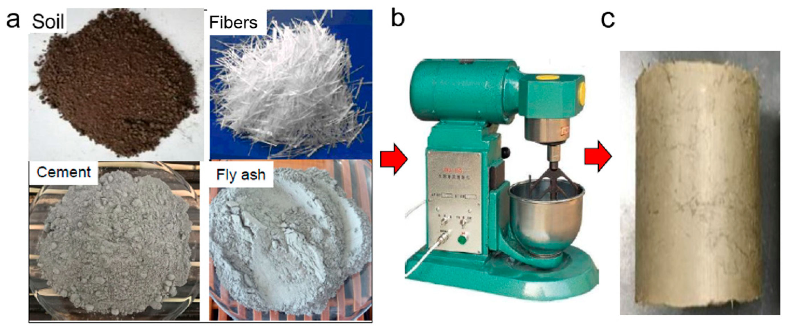
Figure 2.
Particle size distribution of the soft clay.
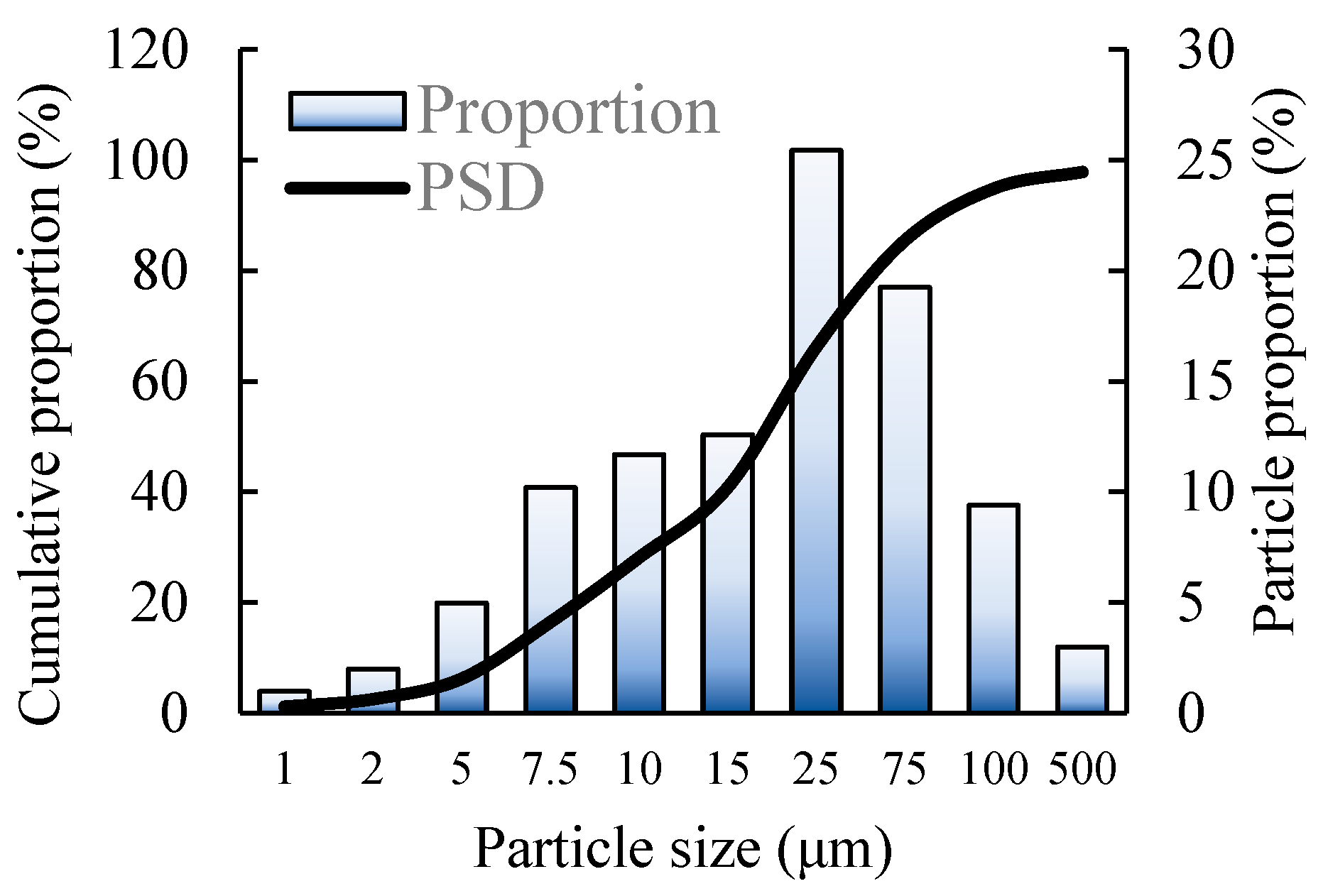
Figure 3.
Stress–strain curves of the stabilized soft clay reinforced by fibers with different lengths: (a) L = 5 mm, (b) L = 10 mm, and (c) L = 15.
Figure 3.
Stress–strain curves of the stabilized soft clay reinforced by fibers with different lengths: (a) L = 5 mm, (b) L = 10 mm, and (c) L = 15.
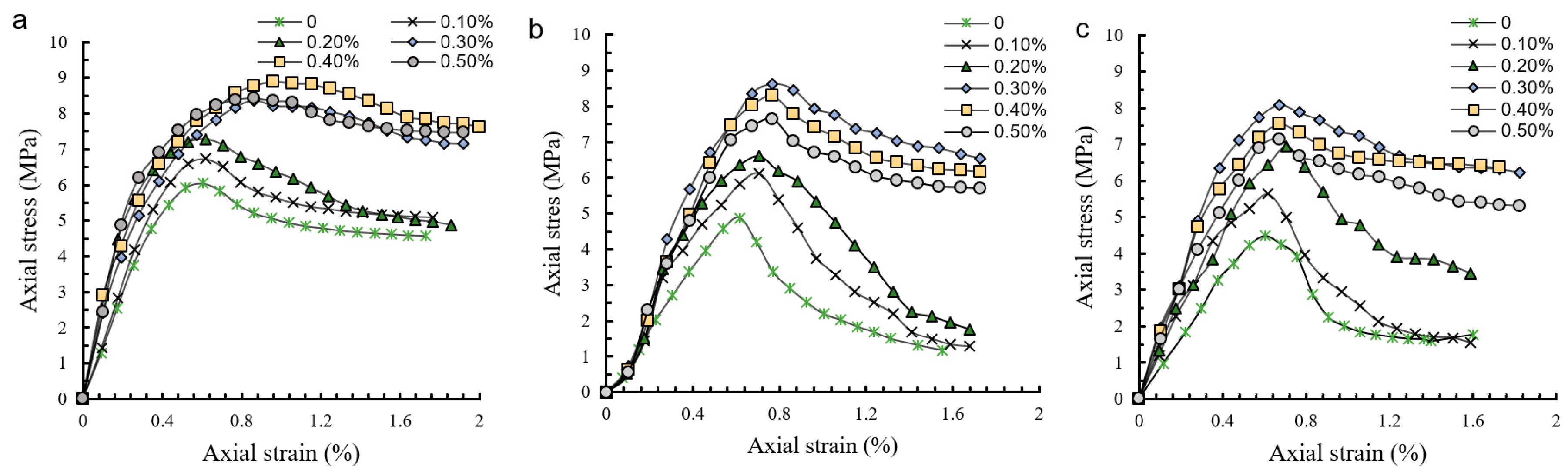
Figure 4.
Fracture morphology of the soil specimens: (a) initial phase, (b) damage phase, and (c) destruction state.
Figure 4.
Fracture morphology of the soil specimens: (a) initial phase, (b) damage phase, and (c) destruction state.

Figure 5.
Compressive strength of the specimens modified by glass fibers: (a) short-cut fibers; (b) medium-cut fibers; (c) long-cut fibers.
Figure 5.
Compressive strength of the specimens modified by glass fibers: (a) short-cut fibers; (b) medium-cut fibers; (c) long-cut fibers.

Figure 6.
Microstructural morphology of cemental sand material at different states: (a) hydration products before destruction, (b) fibers in the sample before destruction, and (c) fiber pulling after failure.
Figure 6.
Microstructural morphology of cemental sand material at different states: (a) hydration products before destruction, (b) fibers in the sample before destruction, and (c) fiber pulling after failure.

Figure 7.
Schematic diagram of microelements under external loading.
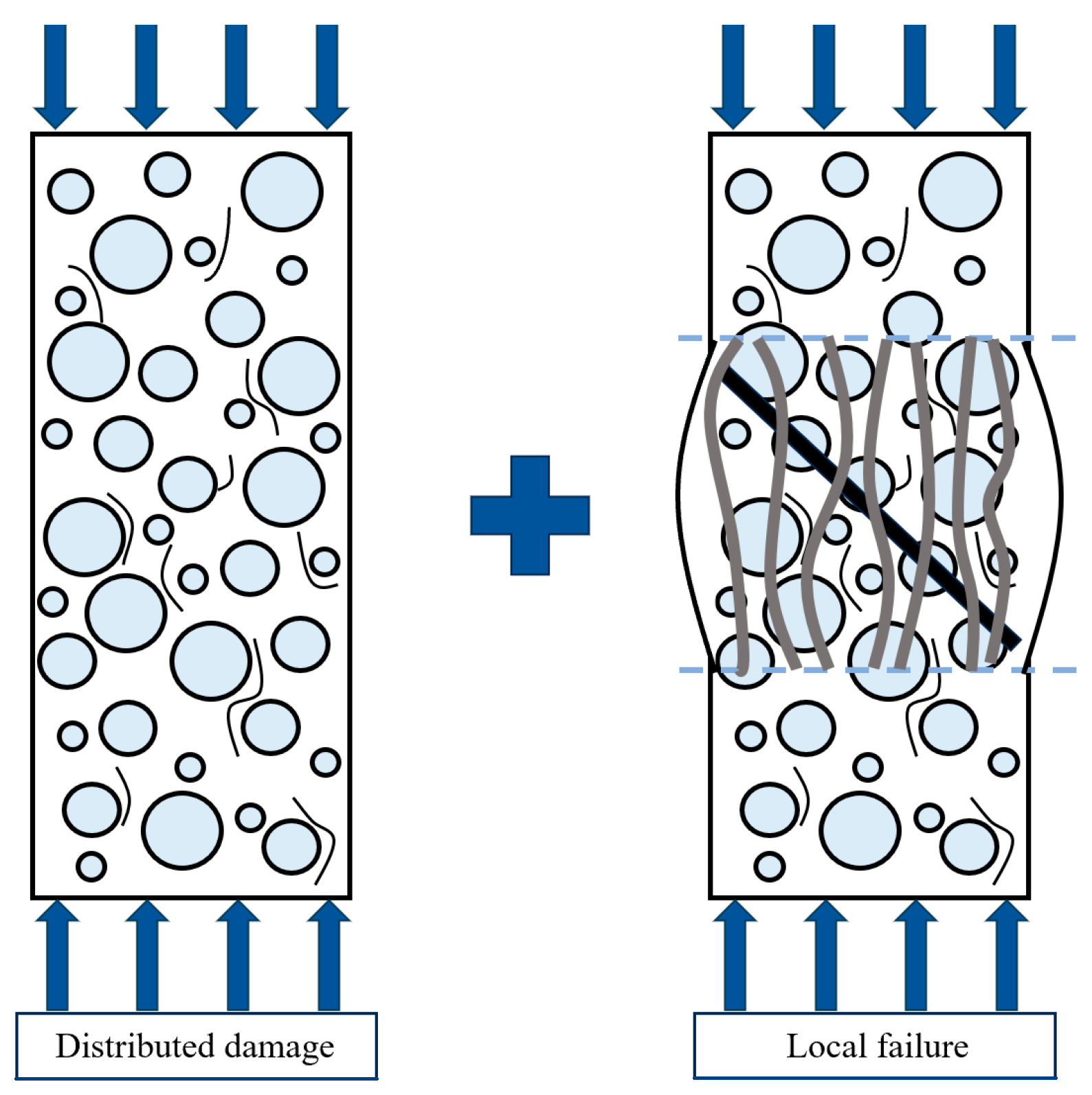
Figure 8.
The measured and fitting results of the stress–strain curves.

Table 1.
Physical and chemical properties of the soft clay.
| Properties | Moisture Content (%) | Liquid Limit (%) | Plastic Limit (%) | Plasticity Index | Relative Density | Clay Content (%) | Organic Matter Content (%) | pH Value |
|---|---|---|---|---|---|---|---|---|
| Value | 29.40 | 41.54 | 21.01 | 20.53 | 2.71 | 91.10 | 3.71 | 7.91 |
Table 2.
Chemical composition of the soft clay.
| Ion Types | Cl− | SO42− | Al3+ | Mg+ | Na+ | Ca+ |
|---|---|---|---|---|---|---|
| Content (%) | 9.4 | 2.3 | 5.0 | 2.4 | 15.1 | 1.6 |
Table 3.
Major physical properties of the glass fibers.
| Fiber Length (mm) | Single Filament Diameter (μm) | Density (g/cm3) | Elongation (%) | Elastic Modulus (GPa) | Tensile Strength (MPa) | Corrosion Resistance | Dispersion |
|---|---|---|---|---|---|---|---|
| 3–20 | 10 | 2.13 | 29 | 12.02 | 948 | Strong | Good |
Table 4.
The mix ratio of the stabilized soft clay.
| Materials | Clay | Cement | Fly Ash | Water |
|---|---|---|---|---|
| Mass ratio (%) | 62.5 | 12 | 3 | 22.5 |
Table 5.
Experimental factor design.
| Test No. | Fiber Length (mm) | Fiber Content (%) |
|---|---|---|
| F0 | - | 0 |
| F1, F2, F3, F4, F5 | 15 | 0.1, 0.2, 0.3, 0.4, 0.5 |
| F6, F7, F8, F9, F10 | 10 | 0.1, 0.2, 0.3, 0.4, 0.5 |
| F11, F12, F13, F14, F15 | 5 | 0.1, 0.2, 0.3, 0.4, 0.5 |
Table 6.
The values of fitting parameters a and b.
| Fiber Content (%) | a | b |
|---|---|---|
| 0 | 1.895 | 0.671 |
| 0.1 | 1.901 | 0.543 |
| 0.2 | 2.231 | 0.488 |
| 0.3 | 2.522 | 0.501 |
| 0.4 | 2.813 | 0.613 |
| 0.5 | 2.864 | 0.726 |
Disclaimer/Publisher’s Note: The statements, opinions and data contained in all publications are solely those of the individual author(s) and contributor(s) and not of MDPI and/or the editor(s). MDPI and/or the editor(s) disclaim responsibility for any injury to people or property resulting from any ideas, methods, instructions or products referred to in the content. |
© 2024 by the authors. Licensee MDPI, Basel, Switzerland. This article is an open access article distributed under the terms and conditions of the Creative Commons Attribution (CC BY) license (https://creativecommons.org/licenses/by/4.0/).
Share and Cite
MDPI and ACS Style
Yan, T.; Zhang, X.; Cai, S.; Zhou, Z.; An, R.; Zhang, X. Mechanical Characteristics and Damage Constitutive Model of Fiber-Reinforced Cement-Stabilized Soft Clay. Appl. Sci. 2024, 14, 1378. https://doi.org/10.3390/app14041378
AMA Style
Yan T, Zhang X, Cai S, Zhou Z, An R, Zhang X. Mechanical Characteristics and Damage Constitutive Model of Fiber-Reinforced Cement-Stabilized Soft Clay. Applied Sciences. 2024; 14(4):1378. https://doi.org/10.3390/app14041378
Chicago/Turabian StyleYan, Tiecheng, Xingyuan Zhang, Sutong Cai, Zefeng Zhou, Ran An, and Xianwei Zhang. 2024. "Mechanical Characteristics and Damage Constitutive Model of Fiber-Reinforced Cement-Stabilized Soft Clay" Applied Sciences 14, no. 4: 1378. https://doi.org/10.3390/app14041378
Note that from the first issue of 2016, this journal uses article numbers instead of page numbers. See further details here.