Article

Tunable Perforated Panel Sound Absorbers for Variable Acoustics Room Design

1
Department of Physics, Systems Engineering and Signal Theory, University of Alicante, 03690 San Vicente del Raspeig, Spain
2
Institute for Sustainability and Innovation in Structural Engineering (ISISE), Advanced Production and Intelligent Systems (ARISE), Department of Civil Engineering, University of Coimbra, 3030-788 Coimbra, Portugal
*
Author to whom correspondence should be addressed.
Appl. Sci. 2024, 14(5), 2094; https://doi.org/10.3390/app14052094
Submission received: 29 January 2024 / Revised: 24 February 2024 / Accepted: 26 February 2024 / Published: 2 March 2024
(This article belongs to the Special Issue Advances in Architectural Acoustics and Vibration)

Abstract

:
Variable acoustics systems are promising engineering developments for multi-purpose rooms and workspaces in many buildings. However, due to space requirements associated with most of the tuning devices used for that purpose, these solutions are hardly adopted in practice. In this work, two innovative tunable sound absorbers that cope with this drawback are proposed, one consisting of rotating perforated panels and the other being a panel with an iris-type aperture. Compared with conventional perforated panel sound absorbers, the designed solutions yield a variable open area ratio system, whose configuration allows tuning the absorption bandwidth without misusing space. To assess their sound absorption coefficient, impedance tube experiments were carried out following the standardized method described in ISO 10534-2 over specimens fabricated for this purpose using laser cutting and additive manufacturing technology. The results not only show their good sound absorption performance but also highlight their tuning capabilities. Complementarily, a model based on the ray tracing method was developed to evaluate the performance of these solutions in a case study room, for different occupancy levels, with the results supporting the previous assertions and revealing the improved intelligibility features when used in such scenarios. The proposed solutions, together with the prediction model, provide a feasible approach for the design and development of tunable sound absorbers in variable room acoustics.

1. Introduction

The acoustic design of a room is a task of great interest in building engineering that involves considering several aspects such as its dimensions, capacity, geometry, and, foremost, its acoustic elements (i.e., sound absorbers, diffusers, and surface-exposed materials). The choice of these elements may depend on the required intelligibility or reverberation conditions, these being majorly determined by the room’s purpose: speech and/or music [1]. In this context, the use of sound absorbers is very important to improve the acoustic quality of a room as it reduces the reverberant sound pressure level (i.e., minimizes the number of reflections). A complete guide for the modeling and design of passive sound absorbers can be found in the books by Cox and D’Antonio [2] and Allard and Atalla [3]. Among these, micro-perforated absorbers are of great interest because of their higher durability and enhanced structural features when compared to traditional porous media such as foams and fibers. These resonant systems were suggested in a pioneering work by Maa [4] and much research has been carried out ever since on their application to room acoustics [5]. Even though these devices have been successfully used through the years, when it comes to the design of multi-purpose rooms, there exists a growing interest in the development of sound absorbers with variable tuning capabilities [6].
Several approaches for variable acoustics room design exist, ranging from architectural solutions [7] to the use of active sound systems [8] or adjustable passive sound absorbers [9]. As for the latter, recent advances in the field of acoustic metamaterials have given rise to many innovative designs yielding reconfigurable structures. In a recent work by Ma et al. [10], it was demonstrated that quiet zones and hotspots can be created in a reverberating environment by using an actively reconfigurable acoustic metasurface. Some other examples are metasurfaces with nesting helical tracks [11], the introduction of a rotatable plate inside a semi-cylindrical cavity [12], or the use of a manual slider [13]. Regarding tunable absorbers involving perforated panels, several research works can be also found in the literature, such as the development of a tunable absorber/diffuser using micro-perforated panels [14] or the study of an origami-based foldable sound absorber based on micro-perforated resonators [15]. Alternative but more complex solutions are those based on the use of hybrid passive-active systems consisting of a micro-perforated panel and a loudspeaker [16], micro-perforated dielectric elastomer actuators [17], or compact piezoelectric micro-perforated panel absorbers [18].
In this work, two different tunable perforated panel sound absorbers for variable acoustics room design are proposed. More specifically, two rotating perforated panels and a panel with an iris-type aperture make up variable open area ratio systems, hereafter referred to as Tunable Solution A (TS-A) and Tunable Solution B (TS-B), respectively. The sound absorption performance of both solutions was experimentally assessed using an impedance tube set up according to the ISO 10534-2 standard [19]. For this purpose, several specimens were fabricated using laser cutting technology over Poly (methyl methacrylate) (PMMA) plastic. A parametric study for different configurations was carried out, highlighting their tuning capabilities. Additionally, the influence of employing these solutions in diffuse field conditions was analyzed for a case study room by following a prediction scheme based on the ray tracing method. In doing so, the Reverberation Time (RT), the Definition (D50), and the Clarity (C80) were obtained at several room positions for different occupancy levels (i.e., number of people in the room), thus confirming the potential of using tunable perforated panel sound absorbers for variable acoustics room design.
This paper is organized as follows: Section 2 describes the conventional perforated panel sound absorber and the proposed tunable solutions along with their fabrication details and operating modes. In Section 3, the experimental setup used to measure their sound absorption coefficient under normal incidence and the ray tracing method implemented to analyze their behavior in diffuse field conditions are briefly outlined. Section 4 presents the sound absorption results for the different configurations of the prepared solutions and analyses the influence of applying these in a case study room by evaluating classical room-acoustic parameters. Further, some remarks concerning the in situ implementation of these absorbers that may be worth considering are also given. Finally, Section 5 summarizes the main conclusions of this research.

2. Materials

2.1. Perforated Panel Sound Absorber

A perforated panel consists of a flat rigid surface with perforations, typically holes or slits, in which attenuation is produced by visco-thermal losses in these apertures. The acoustic behavior of a perforated panel absorber is described in many well-known references [2,3,4]. In brief, a resonator system is achieved when a perforated panel is backed by an air cavity and a rigid wall, with its sound absorption performance determined by its geometrical characteristics, namely the size of the perforations, open area ratio (i.e., ratio of perforated area to the total area), panel thickness, and air cavity depth. In general, the air cavity depth determines the frequency range, in which the sound absorption of the resonator is more effective so that an increase in its depth shifts the peak absorption towards lower frequencies. Although a perforated panel absorber with variable air cavity depth may be considered a tunable solution, implementing such systems for variable acoustics room design involves a loss of space when the resonator is not configured in its deepest air cavity configuration, which motivates the search for alternative tunable solutions, such as those described in the following sections.

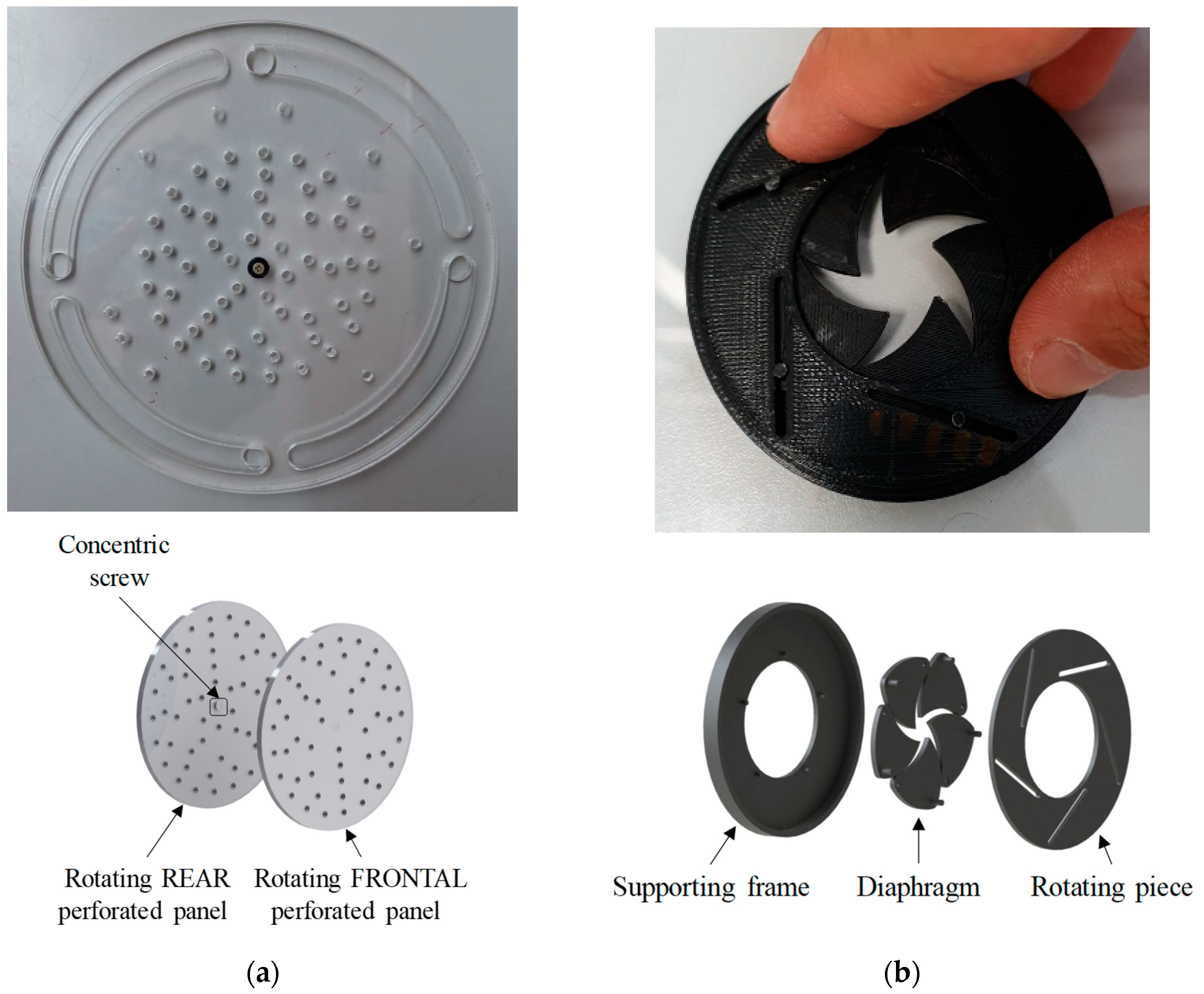
2.2. Tunable Solution A (TS-A): Rotating Perforated Panels

The first tunable perforated panel absorber solution proposed is depicted in Figure 1a. It consists of two rotating circular perforated panels attached using a concentric screw so that the perforations can be aligned or hidden resulting in different hole distribution patterns. In this manner, a variable open area ratio system is attained, creating a tunable sound absorber. Reducing the open area ratio of a perforated panel absorber also shifts the peak frequency of the resonator towards lower frequencies, without the need to modify the total dimensions of the absorber (i.e., the air cavity depth), this being the main advantage when compared to the variable air cavity system described above.
The perforated panels were fabricated using a GESMAIN LASER CO2 1309 laser cutting machine available in the Fab Lab facilities at the University of Alicante using flat PMMA plastic plates. Details on the geometrical characteristics of the fabricated perforated plates, whose values were chosen as a proof-of-concept, are summarized in Table 1. The device herein designed was conceived with a circular cross-section to be mounted on an impedance tube for experimental assessment, even though other implementations may be developed based on the same concept. Some suggestions on this point will be given in Section 4.3.

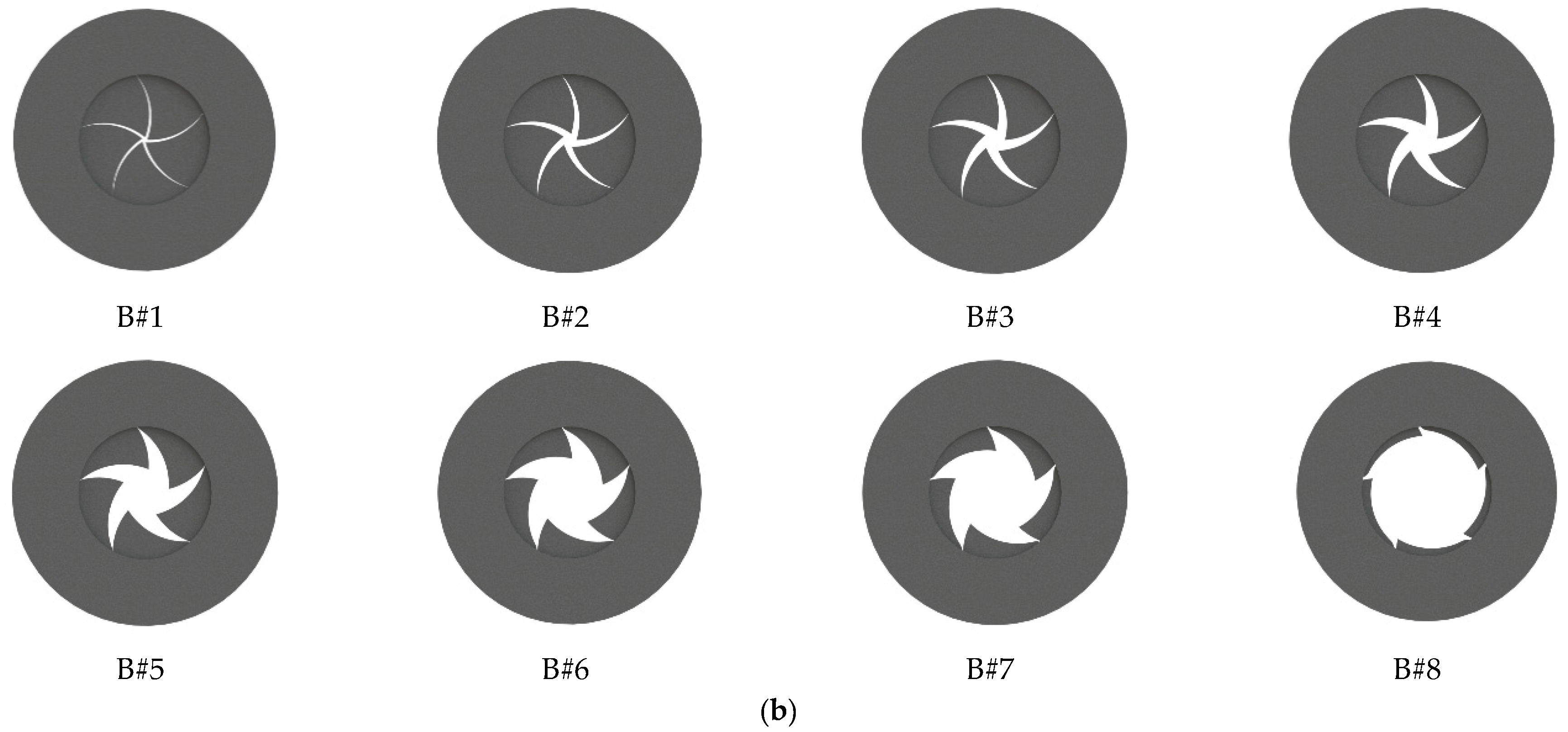
2.3. Tunable Solution B (TS-B): Iris-Type Aperture

The second tunable solution to be analyzed is depicted in Figure 1b and consists of a thin diaphragm structure with an aperture at its center resulting in the iris-type aperture. By rotating the diaphragm clockwise, the aperture is narrowed, and this is the opposite when the rotation is carried out counterclockwise. Usually, smaller apertures increase the viscous friction as the acoustic wave propagates throughout these, which in turn enhances the dissipation phenomena. However, a reduction in the size of the perforations also leads to a reduction in the open area ratio (as in the TS-A), with the sound absorption performance of this solution linked to both geometrical parameters. At the same time, it can be remarked that the peak frequency of the resonator system can be shifted while its total dimensions remain unchanged. Regarding the fabrication procedure, a BQ model Hephestos 2 3D printer, using PLA (poly-lactic acid) filament of 1.75 mm, served in this case both to prepare the diaphragm structure and the supporting frame in which the former was assembled. In this regard, it should be noted that the microporosity of the diaphragm manufactured using 3D printing may increase the dissipation losses and therefore influence the sound absorption performance of the absorber [20]. Some geometrical data of the resulting structure are also given in Table 1; the dimensions being once more chosen with a proof-of-concept purpose.
Figure 1. Proposed tunable perforated panel sound absorbers, images, and schematic concepts: (a) rotating perforated panels system (TS-A) and (b) iris-type aperture system (TS-B).
Applsci 14 02094 g001
Table 1. Geometrical characteristics of the tunable perforated panel solutions.
SolutionPanel Thickness (mm)Perforation Radius (mm)Open Area Ratio (%)
TS-A41.50.6–5.6
TS-B2-0.7–14.1

3. Methods

3.1. Impedance Tube Setup

Once the tunable perforated panel solutions were fabricated, laboratory experiments were carried out using an impedance tube set up to determine their normal incidence sound absorption coefficient when mounted as a resonator system. The measurement procedure used implements the transfer function method which is well described in the standard ISO 10534-2 [19]. For this purpose, a custom-made circular cross-section stainless steel tube, 88 mm in diameter and 4 mm in thickness, was used together with two 4188 type ½ inch microphones (Brüel&Kjær, Nærum, Denmark) and the OR34 Compact Analyzer acquisition system (OROS, Lieusaint, France), with the sound source being a CP-380M compression driver (Beyma, Valencia, Spain). The sound source was located at one end of the tube and the perforated panel solution under test at the other end, with a sample holder attached to the latter using adjustable screws and threaded bars together with an additional movable rigid piece to achieve a backing air cavity. A random excitation was provided to the driver from the analyzer and the pressure transfer function was measured using the two microphones mounted flush with the inner surface of the tube and spaced 80 mm (cut-off frequency around 2000 Hz). Given that a parametric study was to be performed as a function of the open area ratio (TS-A) and iris aperture (TS-B), pilot holes were drilled on the perimeter of each sample to guarantee a more precise placement on the sample holder of the tube (see Figure 1). It should be also mentioned that the samples were withdrawn from the sample holder every time a new configuration of either tunable solution A or B was to be tested, carefully checking that the holes were properly aligned and the aperture size was suitably fitted, respectively. As for the post-processing of the acquisition data, in-house MATLAB software v. 2021b was used to calculate the sound absorption coefficient from the measured pressure data using the corresponding expressions in [19].

3.2. Ray Tracing Method

To study the influence of using the above solutions as part of a variable acoustic system, simulations for a case study room were performed by using a self-developed MATLAB v. 2021b code that implements the ray tracing method. While several numerical approaches have been recently proposed for the acoustic simulation of rooms with perforated panel absorbers, either using the finite element method (FEM) [21,22] or the finite-difference time-domain (FDTD) method [23,24], the ray tracing approach was herein chosen for the sake of simplicity and computational efficiency, as is usual in room acoustics design. The implementation carried out in this work followed a similar procedure to that used in a previous work by the authors [25], which proved to be successful in the simulation of a conceptual auditorium.
In the present work, a room with dimensions of 5 m × 9 m × 3 m, with a total volume of 135 m3, was prepared using SketchUp 3D design software, and the simulations were performed using around 50,000 rays to obtain impulse responses of 2 s length at different receiver positions when an omnidirectional source is placed in a representative point. From the impulse response data, it was straightforward to calculate classical room-acoustic parameters, such as the Reverberation Time (RT), the Definition (D50), and the Clarity (C80), whose definitions can be found in several classic reference books on architectural acoustics, such as the one by Vorländer [26]. Simulations were performed for different occupancy levels both without any absorber (except for reference lining materials on each surface) and with the TS-A solution described in Section 2, this being positioned in the rear wall of the room and in one-third of the surface of the lateral adjacent walls (the standard implementation solution of absorbing material to control reverberation in a room used for lectures or classes, for example). Insomuch as the model reproduces a diffuse field scenario, it was necessary to calculate the diffuse field sound absorption coefficient of the proposed solutions from the measured normal incidence sound absorption data by using well-known formulas represented by equations (11.89) to (11.91), which can be found in Chapter 11 in [3]. In this regard, the particular solution (TS-A) chosen to highlight the tuning capabilities of the proposed systems in diffuse field conditions was approximated as locally reacting as the dimensions of the perforations are much smaller than the smaller wavelength of interest (i.e., the sound propagation in each pore depends only on the pressure of the air above the pore). Corresponding values of these sound absorption coefficients will be given in Section 4.2. For the remaining lining materials, absorption data from the literature were used [2], as summarized in Table 2. Figure 2 shows the resulting geometry along with the identification of all the lining materials and the location of the source and receivers.

4. Results and Discussion

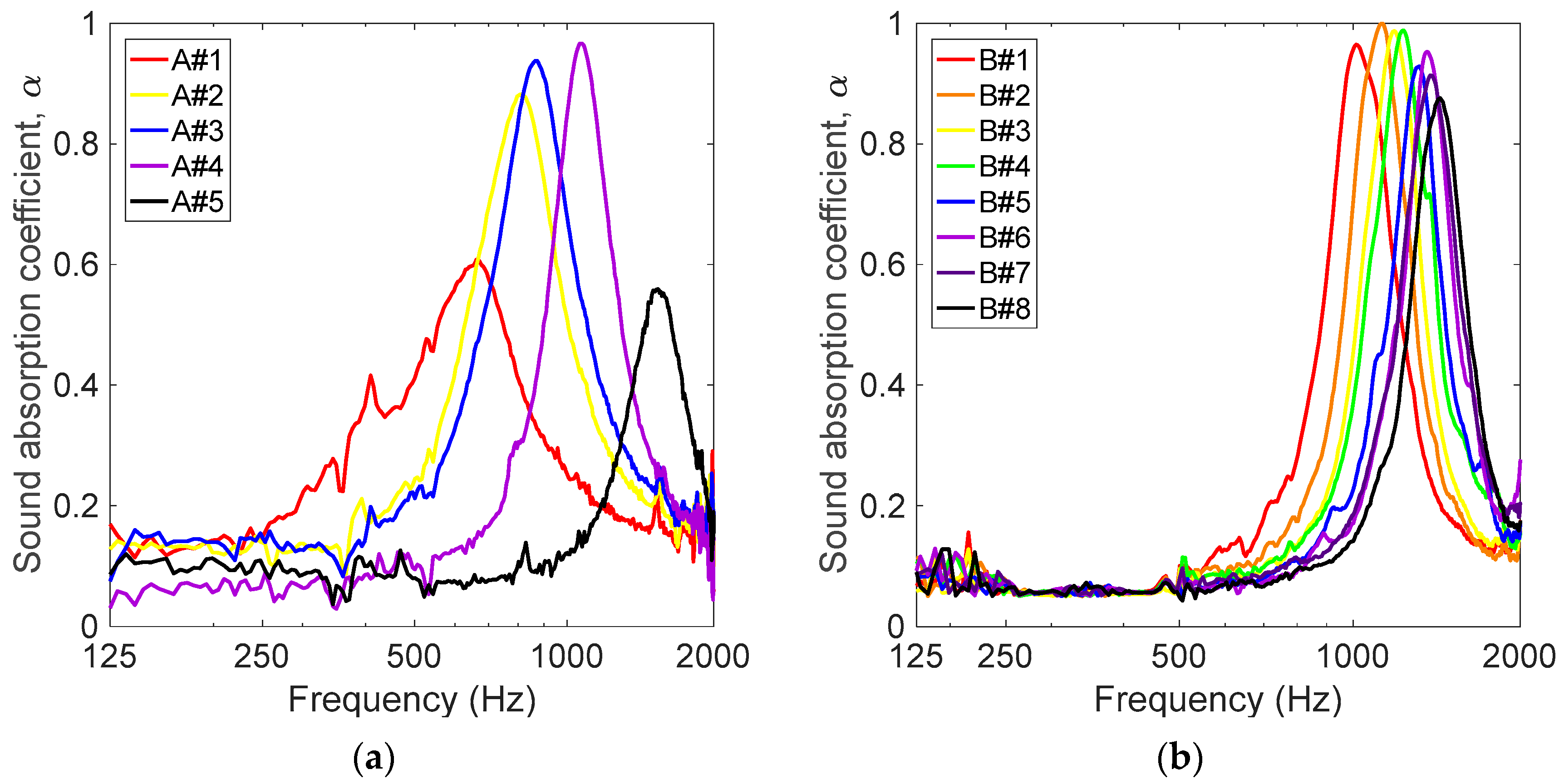
4.1. Parametric Study of the Different Solutions in Terms of Sound Absorption

First of all, the tuning capabilities of the proposed perforated panel absorber solutions were explored. To this end, the effect of varying their geometrical characteristics was assessed by conducting a parametric study for several configurations measuring the sound absorption coefficient using an impedance tube. In the case of the variable open area ratio solution (TS-A), the circular perforated panels were rotated to attain five different hole distribution patterns, whereas in the case of the iris-type solution (TS-B), the diaphragm was regulated to obtain eight different aperture sizes. In both cases, the backing air cavity depth was set to 10 mm. Figure 3 shows schematic representations of the hole distribution patterns and the diaphragm openings analyzed for both tunable solutions. Open area ratio data (in %) for each of the studied configurations of both types of solution are also provided in Table 3. Results of the experimentally measured sound absorption coefficient of both solutions for each configuration are shown in Figure 4.
The sound absorption curves provided by solution TS-A (Figure 4a) indicate that a reduction in the number of perforations aligned through both panels from fifty holes (A#5, with open area ratio of 5.6%) to five holes (A#1, with open area ratio of 0.6%) shifts the resonance peak to lower frequencies from around 1500 Hz to 650 Hz, with the three intermediate sound absorption curves achieving higher peak values. This trend is also observed for solution TS-B (Figure 4b) as the size of the aperture gets reduced from an open area ratio of 14.1% (B#8) down to 0.7% (B#1). As mentioned above, reducing either the number of perforations in TS-A or the aperture size in TS-B implies a decrease in the open area ratio and hence a lower resonance frequency. Moreover, reducing the aperture size in TS-B further increases the dissipation phenomena in most analyzed cases and, as a result, enhances the amplitude of peaks in the sound absorption curve. As was mentioned in Section 2.3, the use of 3D printing methodology in the fabrication of the TS-B may lead to additional visco-thermal losses due to the microporosity resulting from this fabrication process. However, there are other factors which may also influence the attenuation of the panel, as is the case of the surface roughness. In this regard, some authors have investigated these effects using computational models [27] or analyzed the case of a coiled-up resonator system using different additive manufacturing techniques [28]. All the same, the previous results show the good absorption performance of the proposed solutions and highlight their tuning capabilities, which are their main advantages when compared to traditional variable air cavity systems, as they avoid the misuse or loss of room space.

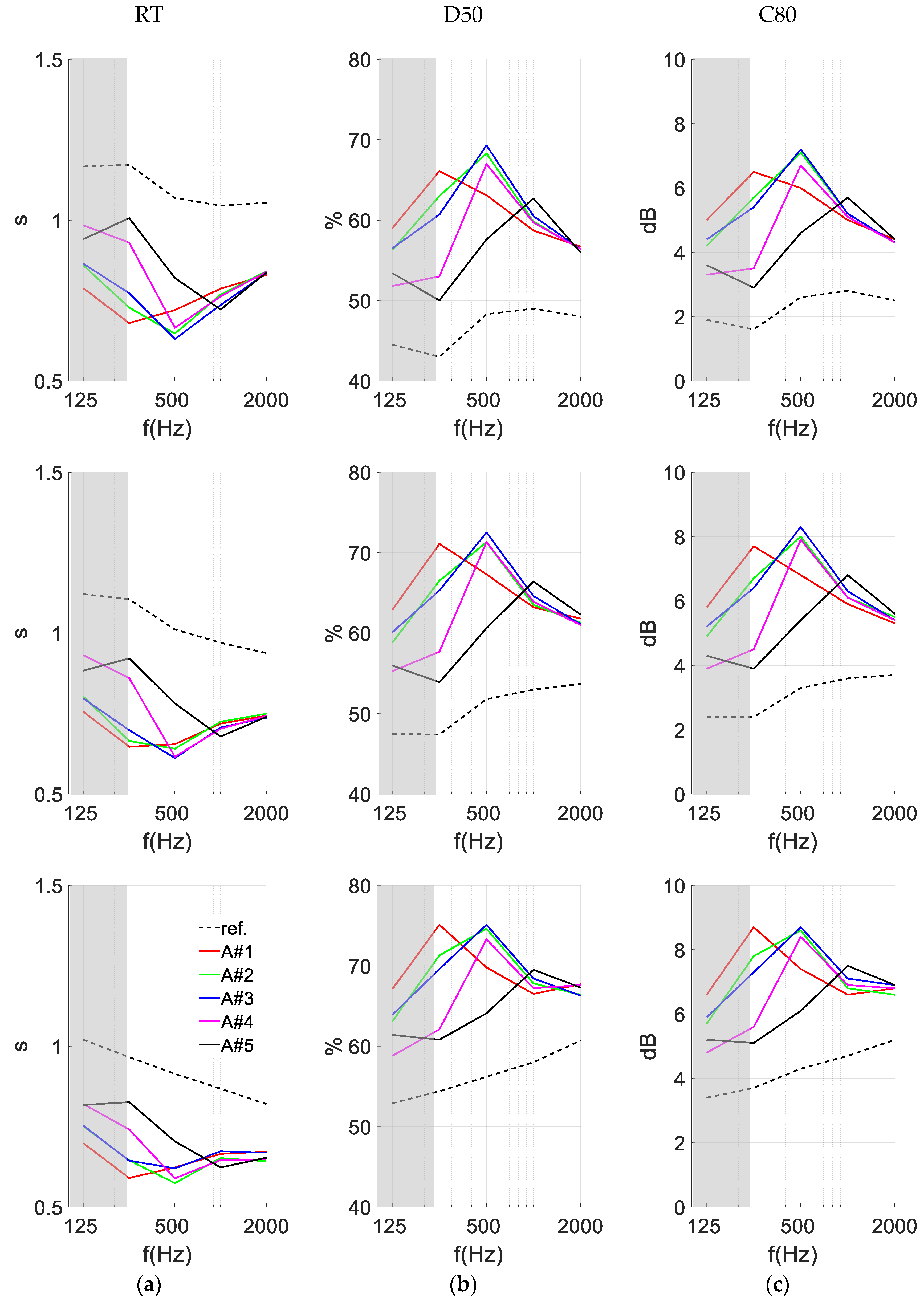
4.2. Case Study: Application to Variable Acoustics Room Design

Next, the use of the TS-A variable solution was analyzed under diffuse field conditions using the ray tracing method in the case study room, as described in Section 3.2. For this purpose, the Reverberation Time (RT), the Definition (D50), and the Clarity (C80) were calculated from the impulse response obtained at each of the receiver positions for different room occupancy levels: empty, one-third occupation, and full occupation. As mentioned previously, diffuse field values of the sound absorption coefficient were estimated from the measured values depicted in Figure 4a by using the methodology described in [3], the resulting data being presented in Table 4.
This analysis was intended to show how the presence of the proposed variable acoustics system may help in controlling the acoustic environment inside the room, acting in conjunction (and eventually compensating) with the occupation by people. Besides the full and empty room cases, an intermediate case has been introduced, showing the effect of the system for one-third of occupation to further illustrate the effect of the system in in-between occupancy conditions.
Figure 5 shows the average results for the three parameters mentioned above as a function of octave frequency bands. Results are shown for a reference case (i.e., without a tunable absorber solution) and different occupancy levels for each of the five configurations of variable solution TS-A analyzed in the previous section. It should be noted that, due to the small volume of the room and its RT being around 1.2 s at lower frequencies, the expected value of Schroeder’s frequency (below which the room is expected to exhibit a modal behavior) is around 185 Hz. Thus, simulations using the ray tracing process are only expected to provide meaningful results above this frequency and, consequently, although the results at 125 Hz are presented in the plots, a gray area has been added to indicate that they are outside the range of validity of the model. For lower frequency analysis, more accurate results may only be obtained by using alternative approaches based on numerical methods to solve the wave equation, such as the finite element method or boundary element method, and also include more detailed properties such as complex surface impedance. An example of this approach can be found in the recent work by Soares et al. [29].
As expected, results show that, as the occupancy level of the room increases, a reduction in the RT and, consequently, an improved Definition and Clarity, are achieved due to the extra sound absorption linked to the higher number of people in the room. On the other hand, the RT is reduced at the frequency of maximum sound absorption of the corresponding tunable configuration, whereas the D50 and C80 increase, thus improving the clarity or intelligibility of speech as the energy of sound reflections is reduced. Specifically, a shift of two octave bands from 1000 Hz to 250 Hz can be achieved by using the proposed tunable solution.
Analyzing the results in more detail, when no occupants are inside the room, activating more absorbent solutions helps to decrease the global reverberation and increase the Definition (D50) and Clarity (C80). It is particularly interesting to note that configuration A#1, which has a lower perforation rate but exhibits a low resonant frequency, allows the good control of the reverberation and of the quality parameters (D50 and C80) throughout the analyzed frequency range. In the opposite case, when a full room is assumed, opting for solutions with higher absorption coefficients may induce an excessively “dry” acoustic environment, with reverberation times below 0.7 s, if the A#1 solution is used; thus, for such a case, the A#1 configuration or even a solution with all perforations closed (reflective) could be used for the better control of the room’s acoustic environment. Observing the results for the one-third occupation configuration, a very similar trend can be seen, although with a less pronounced decrease in reverberation with the different solutions.
It should also be noted that, besides the cases studied here, in which the configuration is homogeneous throughout the treated surfaces, other possible combinations could be used (for example half of the area with A#1 and the remaining half with A#4), allowing us to adapt the room’s behavior to reach intermediate values between the reference (all rigid surfaces) value and the values obtained for the three parameters with the A#1–A#5 configurations. The use of such combinations could even allow us to control and adjust the acoustic behavior of the space so that it remains approximately constant, independent of the room’s occupation. An example of an architectural approach developed to provide good speech intelligibility by optimizing the dimensions and positions of the acoustic treatments for different audiences can be found in [30].

4.3. Remarks on the In Situ Implementation

One of the main advantages of the systems configurations presented in this work is the possibility of modifying, within a given frequency range, acoustic properties, such as sound absorption. This particularity opens the possibility of establishing variable acoustic solutions that allow the user to adapt to the conditions of a room according to different uses and needs. This type of concept (variable acoustics) has been traditionally employed in architectural acoustics; however, as a general rule, using manual operation allows for a change in the solution. Alternatively, variable acoustic systems such as those proposed in this paper can be easily automated using an electromechanical system consisting of an engine (stepper or servo) coupled, in the first case, to the axis of the panel and attached to one of the sides of the assembly, and, in the second case, to a gear system consisting of a pinion (coupled to the motor) and a wheel incorporated as a rotation element of the panel (currently formed by a non-toothed wheel). The device can be driven using a control unit, and the different panel positions can be set via software or hardware (e.g., using light-dependent resistors or capacitive sensors). In recent years, the rise of IoT (Internet of Things) devices has led to the appearance of many low-cost electronic development systems capable not only of controlling inputs and outputs (analog/digital) but also managing communication and information flow between units in an agile and efficient way [31]. Odroid, Raspberry PI, or Arduino are some of the most popular recommendations thanks to their performance and multiple connections [32]. Some additional considerations are that this type of system would allow the interconnection of different elements, thus composing a network of variable acoustic solutions distributed throughout any architectural space. Moreover, it would also be possible to create supervisory control and data acquisition (SCADA) mobile applications capable of remotely controlling the installations. Programming languages such as Java, Python, or Dart, with the latter included in Flutter, Google’s SDK for the development of multiplatform applications, could be useful when implementing tools for mobile devices. Therefore, once the corresponding technical requirements are met, it would be possible to consider their application when a reduction in the basic reverberation time is needed [33] for optimizing multifunctional performance spaces [34] in the form of innovative implementations [35] or as artworks [36]. Regarding the modeling of the proposed solutions, the use of artificial neural networks [37,38] may be a useful alternative to more sophisticated numerical approaches in the design stage before their practical implementation in a room.

5. Conclusions

This work proposes two different tunable perforated panel sound absorbers for variable acoustics room design: rotating perforated panels (tunable solution TS-A) and an iris-type aperture (tunable solution TS-B). Prototypes of these tunable solutions, TS-A and TS-B, were manufactured using laser cutting and additive manufacturing technology, respectively, and the sound absorption coefficient of the prepared specimens was measured using an impedance tube setup when used as resonator systems. Each of these solutions yields five (tunable solution TS-A) and eight (tunable solution TS-B) different tuning configurations, thus allowing the choice of a frequency range in which the absorber works. Unlike conventional perforated panel resonator systems, the proposed solutions exhibit both good sound absorption performance (peak values above 0.8 for most analyzed configurations) and tuning capabilities (up to two octave bands) while avoiding losing space when the resonator is not configured in its deepest air cavity configuration. This last feature is of great interest in most practical cases of room acoustics as it allows dealing with space constraints, with these requirements being the main challenges in most passive variable acoustics systems. Furthermore, by using the ray tracing method it was found that the application of one of these solutions in a case study room may not only serve to modify its reverberation but also to improve speech clarity and intelligibility. In summary, preliminary results showed the interesting potential of the proposed solutions and encourage further research for their practical implementation in building engineering (e.g., development of guidance formulas to achieve a certain absorption peak and bandwidth in perforated panel sound absorbers with irregular hole distribution).

Author Contributions

Conceptualization, J.C. and P.P.-M.; methodology, J.C. and P.P.-M.; investigation, J.C., P.P.-M., L.G., A.P., A.G., P.A.-M., D.M. and J.R.; writing—original draft, J.C.; writing—review and editing, P.P.-M., L.G., A.P. and P.A-M.; software, L.G.; resources, J.R. All authors have read and agreed to the published version of the manuscript.

Funding

This research was partially funded by FCT—Fundação para a Ciência e a Tecnologia, I.P., by Base Funding (UIDB/04029/2020, doi.org/10.54499/UIDB/04029/2020) and Programmatic Funding (UIDP/04029/2020) of the research unit “Institute for Sustainability and Innovation in Structural Engineering—ISISE”, and under the Associate Laboratory Advanced Production and Intelligent Systems ARISE, reference LA/P/0112/2020. This work was also financed by FEDER funds through the Competitivity Factors Operational Programme—COMPETE within the scope of the project ADJUST—Development of acoustic panels progressively adjustable with smart acting—SII & DT Project CENTRO-01-0247-FEDER-033884.

Institutional Review Board Statement

Not applicable.

Informed Consent Statement

Not applicable.

Data Availability Statement

The raw data supporting the conclusions of this article will be made available by the authors on request.

Conflicts of Interest

The authors declare no conflict of interest.

References

  1. Beranek, L. Concert Halls and Opera Houses: Music, Acoustics, and Architecture; Springer: New York, NY, USA, 2004. [Google Scholar]
  2. Cox, T.; d’Antonio, P. Acoustics Absorbers and Diffusers: Theory, Design and Application; Taylor & Francis: Abingdon, UK, 2009. [Google Scholar]
  3. Allard, J.F.; Atalla, N. Propagation of sound in porous media. In Modelling Sound Absorbing Materials; John Wiley and Sons: Chichester, UK, 2009. [Google Scholar]
  4. Maa, D.Y. Theory and design of microperforated-panel sound-absorbing construction. Sci. Sin. 1975, 18, 55–71. [Google Scholar]
  5. Fuchs, H.V.; Zha, X. Micro-perforated structures as sound absorbers—A review and outlook. Acta Acust. United Acust. 2006, 92, 139–146. [Google Scholar]
  6. Barron, M. Acoustic for multi-purpose use. In Auditorium Acoustics and Architectural Design; Spon Press: London, UK, 2010. [Google Scholar]
  7. Cairoli, M. Architectural customized design for variable acoustics in multipurpose auditorium. Appl. Acoust. 2018, 140, 167–177. [Google Scholar] [CrossRef]
  8. Poletti, M.A. Active acoustic systems for the control of room acoustics. Build. Acoust. 2011, 18, 237–258. [Google Scholar] [CrossRef]
  9. Everest, F.A.; Pohlmann, K.C. Chapter 15: Adjustable Acoustics. In Master Handbook of Acoustics; McGraw-Hill: New York, NY, USA, 2009. [Google Scholar]
  10. Ma, G.; Fan, X.; Sheng, P.; Fink, M. Shaping reverberating sound fields with an actively tunable metasurface. Proc. Natl. Acad. Sci. USA 2018, 115, 6638–6643. [Google Scholar] [CrossRef]
  11. Xie, S.-H.; Fang, X.; Li, P.-Q.; Huang, S.; Peng, Y.-G.; Shen, Y.-X.; Li, Y.; Zhu, X.-F. Tunable double-band perfect absorbers via acoustic metasurfaces with nesting helical tracks. Chin. Phys. Lett. 2020, 37, 054301. [Google Scholar] [CrossRef]
  12. Liu, H.; Wu, J.H.; Ma, F. Dynamic tunable acoustic metasurface with continuously perfect sound absorption. J. Phys. D Appl. Phys. 2021, 54, 365105. [Google Scholar] [CrossRef]
  13. Xiang, X.; Tian, H.; Huang, Y.; Wu, X.; Wen, W. Manually tunable ventilated metamaterial absorbers. Appl. Phys. Lett. 2021, 118, 053504. [Google Scholar] [CrossRef]
  14. Hildebrand, M. Development of tunable absorber/diffuser using micro-perforated panels. J. Acoust. Soc. Am. 2014, 136, 2115–2116. [Google Scholar] [CrossRef]
  15. Jiang, P.; Jian, T.; He, Q. Origami-based adjustable sound-absorbing metamaterial. Smart Mater. Struct. 2021, 30, 057002. [Google Scholar] [CrossRef]
  16. Cobo, P.; Pfretzschner, J.; Cuesta, M.; Anthony, D.K. Hybrid passive-active absorption using microperforated panels. J. Acoust. Soc. Am. 2004, 116, 2118–2125. [Google Scholar] [CrossRef]
  17. Lu, Z.; Shrestha, M.; Lau, G.-K. Electrically tunable and broader-band sound absorption by using micro-perforated dielectric elastomer actuator. Appl. Phys. Lett. 2017, 110, 182901. [Google Scholar] [CrossRef]
  18. Kong, D.Y.; Xie, D.Y.; Tang, X.N.; Hu, M.; Xu, H.; Qian, Y.J. Experimental study of a compact piezoelectric micro-perforated panel absorber with adjustable acoustic property. J. Acoust. Soc. Am. 2020, 147, EL2083. [Google Scholar] [CrossRef]
  19. ISO 10534-2; Determination of Sound Absorption Coefficient and Impedance in Impedance Tubes. International Organization for Standardization: Geneva, Switzerland, 2023.
  20. Zieliński, T.G.; Dauchez, N.; Boutin, T.; Leturia, M.; Wilkinson, A.; Chevillotte, F.; Bécot, F.-X.; Venegas, R. Taking advantage of a 3D printing imperfection in the development of sound absorbing materials. Appl. Acoust. 2022, 197, 108941. [Google Scholar] [CrossRef]
  21. Okuzono, T.; Sakagami, K. A frequency domain finite element solver for acoustic simulation of 3D rooms with microperforated panel absorbers. Appl. Acoust. 2018, 129, 1–12. [Google Scholar] [CrossRef]
  22. Hoshi, K.; Hanyu, T.; Okuzono, T.; Sakagami, K.; Yairi, M.; Harada, S.; Takahashi, S.; Ueda, Y. Implementation experiment of a honeycomb-backedd MPP sound absorber in a meeting room. Appl. Acoust. 2020, 157, 107000. [Google Scholar] [CrossRef]
  23. Toyoda, M.; Eto, D. Prediction of microperforated panel absorbers using the finite-difference time-domain method. Wave Motion 2019, 86, 110–124. [Google Scholar] [CrossRef]
  24. Cingolani, M.; Fratoni, G.; Barbaresi, L.; D’Orazio, D.; Hamilton, B.; Garai, M. A trial acoustic improvement in a lecture hall with MPP sound absorbers and FDTD acoustic simulations. Appl. Sci. 2021, 11, 2445. [Google Scholar] [CrossRef]
  25. Pereira, A.; Gaspar, A.; Godinho, L.; Amado-Mendes, P.; Mateus, D.; Carbajo, J.; Ramis, J.; Poveda, P. On the use of Perforated sound absorption systems for variable acoustics room design. Buildings 2021, 11, 543. [Google Scholar] [CrossRef]
  26. Vorländer, M. Auralization: Fundamentals of Acoustics, Modelling, Simulation, Algorithms and Acoustic Virtual Reality; Springer: Berlin/Heidelberg, Germany, 2008. [Google Scholar]
  27. Ciochon, A.; Kennedy, J.; Leiba, R.; Flanagan, L.; Culleton, M. The impact of surface roughness on an additively manufactured acoustic material: An experimental and numerical investigation. J. Sound. Vib. 2023, 546, 117434. [Google Scholar] [CrossRef]
  28. Fusaro, G.; Babaresi, L.; Cingolani, M.; Garai, M.; Ida, E.; Prato, A.; Schiavi, A. Investigation of the impact of additive manufacturing techniques on the acoustic performance of a coiled-up resonator. J. Acoust. Soc. Am. 2023, 153, 2921. [Google Scholar] [CrossRef] [PubMed]
  29. Soares, M.C.; Carneiro, E.B.; Tenenbaum, R.A.; Mareze, P.H. Low-frequency room acoustical simulation of a small room with BEM and complex-valued surface impedances. Appl. Acoust. 2022, 188, 108570. [Google Scholar] [CrossRef]
  30. Iannace, G.; Sicurella, F.; Colamesta, P.; Gentilin, M. Acoustic project of a conference room of the secondary school “Avenir 33” (Delémont, Switzerland). Can. Acoust. 2018, 46, 31–38. [Google Scholar]
  31. Bhardwaj, H.; Tomar, P.; Skalle, A.; Sharma, U. Chapter 20. Principles and Foundations of Artificial Intelligence and Internet of Things Technology. In Artificial Intelligence to Solve Pervasive Internet of Things Issues; Academic Press: Cambridge, MA, USA, 2021. [Google Scholar]
  32. Hondaveeti, H.K.; Mathe, S.E. A Systematic Literature Review on Prototyping with Arduino: Applications, Challenges, Advantages, and Limitations. Comput. Sci. Rev. 2021, 40, 100364. [Google Scholar] [CrossRef]
  33. Dragonetti, R.; Ianniello, C.; Romano, R. Preliminary acoustic measurements in the Oscar Niemeyer auditorium in Ravello. In Proceedings of the 39th International Congress on Noise Control Engineering 2010, INTER-NOISE 2010, Lisbon, Portugal, 13–16 June 2010. [Google Scholar]
  34. Sadehnia, G.R. Data-driven IoT-platform for optimizing variable acoustics in multifunctional performance spaces. J. Acoust. Soc. Am. 2019, 146, 2851. [Google Scholar] [CrossRef]
  35. Sakagami, K.; Kusaka, M.; Okuzono, T.; Kido, S.; Yamaguchi, D. Three-dimensional MPP space absorbers: An overview of the project and recent development. Proc. Inter-Noise 2020, 261, 358–368. [Google Scholar]
  36. Lee, H.P.; Kumar, S.; Aow, J.W. Proof-of-concept design for MPP acoustic absorbers with elements of art. Designs 2021, 5, 72. [Google Scholar] [CrossRef]
  37. Ciaburro, G.; Iannace, G.; Puyana-Romero, V.; Trematerra, A. A comparison between numerical simulation models for the prediction of acoustic behavior of shredded giant reeds. Appl. Sci. 2020, 10, 6881. [Google Scholar] [CrossRef]
  38. Ciaburro, G.; Iannace, G. Numerical simulation for the sound absorption properties of ceramic resonators. Fibers 2020, 8, 77. [Google Scholar] [CrossRef]
Figure 2. Geometry of the case study room, including the identification of all the lining materials and the location of the source and receivers (created using SketchUp 3D design software). In this figure, a case with one-third seat occupation is illustrated.
Applsci 14 02094 g002
Figure 3. Schematic representation of the possible configurations for the tunable solutions assumed in the parametric study: (a) TS-A (hole distribution patterns A#1 to A#5) and (b) TS-B (diaphragm openings B#1 to B#8).
Applsci 14 02094 g003aApplsci 14 02094 g003b
Figure 4. Measured sound absorption coefficients for each of the analyzed configurations: (a) TS-A and (b) TS-B.
Applsci 14 02094 g004
Figure 5. Average results of the case study room simulated using the ray tracing method for each of the five configurations of variable solution TS-A and different occupancy levels: (a) Reverberation Time, RT; (b) Definition, D50; and (c) Clarity, C80 (top: empty room; center: one-third occupation; and bottom: full occupation). Gray shade indicates frequencies outside the domain of validity.
Applsci 14 02094 g005
Table 2. Sound absorption coefficients (α, [−]) and sound absorption area of furniture elements (A, [m2 per unit]) of the standard solutions (retrieved from [2]).
Frequency
Standard Solution125 Hz250 Hz500 Hz1 kHz2 kHz4 kHz8 kHz
Occupied seat
(m2 per unit)
0.180.240.280.330.370.390.42
Unoccupied seat
(m2 per unit)
0.020.020.030.040.060.080.08
Floor in wood parquet on concrete (α)0.040.040.070.060.060.070.07
Plastered masonry wall (α)0.010.020.020.030.040.050.05
Suspended ceiling (α)0.290.250.250.230.190.190.18
Table 3. Open area ratio for each of the analyzed configurations of both types of solution.
Variable SolutionOpen Area Ratio (%)
TS-AA#1A#2A#3A#4A#5
0.61.21.42.75.6
TS-BB#1B#2B#3B#4B#5B#6B#7B#8
0.71.72.73.96.18.710.614.1
Table 4. Sound absorption coefficients used in the diffuse field simulations for TS-A variable acoustics solution.
Frequency (Hz)
TS-A Variable Solution1252505001 k2 k
A#10.180.300.620.390.25
A#20.230.220.460.590.27
A#30.260.230.390.640.30
A#40.070.110.170.560.28
A#50.160.160.130.210.35
Disclaimer/Publisher’s Note: The statements, opinions and data contained in all publications are solely those of the individual author(s) and contributor(s) and not of MDPI and/or the editor(s). MDPI and/or the editor(s) disclaim responsibility for any injury to people or property resulting from any ideas, methods, instructions or products referred to in the content.

