
Corrosion Monitoring Techniques in Subcritical and Supercritical Water Environments
by
 ,
,
Yanhui Li
1,2,*,
Zhouyang Bai
1,
Limei Xing
1,
Qian Zhang
1,
Shaoming Ding
1,
Yinan Zhang
1,
Pengfei Gao
1,
Zhihong Yu
1 and
Donghai Xu
1 1
Key Laboratory of Thermo-Fluid Science & Engineering, School of Energy and Power Engineering, Xi’an Jiaotong University, Ministry of Education, Xi’an 710049, China
2
Departments of Nuclear Engineering & Materials Science and Engineering, University of California, Berkeley, CA 94720, USA
*
Author to whom correspondence should be addressed.
Appl. Sci. 2024, 14(6), 2350; https://doi.org/10.3390/app14062350
Submission received: 7 February 2024
/
Revised: 3 March 2024
/
Accepted: 4 March 2024
/
Published: 11 March 2024
(This article belongs to the Topic Advances in Non-Destructive Testing Methods, 2nd Volume)
Abstract
:A series of advanced equipment exposed to sub-/supercritical water environments at high temperatures, high pressures, and extreme water chemistry with high salt and dissolved oxygen content faces serious corrosion problems. Obtaining on-site corrosion data for typical materials in harsh environments is crucial for operating and maintaining related equipment and optimizing various corrosion prediction models. First, this article introduces the advantages and disadvantages, usage scenarios, and future development potential of several in situ monitoring technologies, including ultrasonic thickness measurement, the infrared thermography method, microwave imaging, eddy current detection, and acoustic emission. Considering the importance of electrochemical corrosion data in revealing microscale and nanoscale corrosion mechanisms, in situ testing techniques such as electrical resistance probes, electrochemical corrosion potential, electrochemical impedance spectroscopy, and electrochemical noise that can be applied to sub-/supercritical water systems were systematically discussed. The testing platform and typical data obtained were discussed with thick and heavy colors to establish a mechanical prediction model for corrosion behavior. It is of great significance to promote the development of corrosion monitoring techniques, such as breaking through testing temperature limitations and broadening the industrial application scenarios and maturity.
1. Introduction
Supercritical water (SCW) has both temperature and pressure above the critical point of water (374.15 °C and 22.12 MPa) [1], while subcritical water refers to water that is heated above the boiling point and below the critical point, and the system pressure is controlled to keep the water in a liquid state [2]. Due to its unique physical and chemical properties, subcritical or supercritical water has been widely used in energy and environmental protection. In nuclear power generation, the current technologically mature pressurized water reactor and boiling water reactor nuclear power plants have subcritical water as their heat transfer medium (coolant) [3]. Although the Chernobyl and Fukushima nuclear power plant accidents cast a shadow over the development of nuclear power plants, nuclear power remains an efficient and pollution-free source of electricity. The fourth-generation reactor is expected to be put into use after 2030. Promoting commercial small reactors has brought new opportunities for developing nuclear energy [4]. The temperature of the core of modern nuclear power reactors is usually between 260 °C and 320 °C. In this high-temperature and strong irradiation environment, water is prone to ionizing strong oxidants (such as O2 and H2O2). Most of these species are electroactive (i.e., they may participate in charge transfer reactions) [5]. In addition, metal pipelines are subjected to long-term high pressure, and nuclear power plants have been threatened with severe local corrosion damage, such as pitting corrosion and stress corrosion cracking, since their inception [5]. Statistics show that the atomic power events that have occurred globally so far are generally caused by localized corrosion. Additionally, ultra-supercritical plants have gradually replaced low-parameter units and become the primary thermal power plants. Due to the complexity of combustion conditions and gas-solid flow, high-temperature corrosion of water-cooled wall pipes is caused and influenced by various factors [6]. With the improvement of unit parameters and the modification of low NOx burners, the problem of high-temperature corrosion of water-cooled wall pipes has become more serious, which leads to a higher possibility of boiler pipe explosion [7].
On the other hand, corrosion is also a crucial factor affecting the safety of equipment and facilities in the exploration, extraction, transportation, and refining processes of oil and gas [8,9,10,11]. The environment of oil and gas fields is complex and harsh, often characterized by high temperature, high pressure, high salinity, and high mineralization. In harsh subcritical water environments, oil pipes are prone to corrosion and even perforation, seriously affecting oil and gas wells’ average production and operation. As an essential transportation system for underwater oil and gas development, the proportion of accidents caused by corrosion can reach 37%. Once oil and gas field pipelines in long-term service rupture or fail due to corrosion, it will cause substantial economic losses and safety hazards [12].
In addition to the energy field, supercritical water oxidation (SCWO) technology can efficiently and thoroughly degrade various high-concentration organic wastes, such as waste fluid, sludge, and hazardous solid waste, with broad application prospects. However, in SCWO treatment systems, the preheating and reaction initiation stages of the initial liquid or slurry materials and the cooling phase of the corresponding reaction products inevitably undergo transcritical water environments due to the predominant electrochemical corrosion [1,13]. The actual operation of some SCWO demonstration/industrialization plants indicates that the current equipment exposed to the transcritical water environment, such as preheaters, reactor fronts, and coolers for reaction effluents, has the highest risk of corrosion failure [13,14], which is a common bottleneck problem that restricts the industrial promotion of various supercritical water treatment techniques, including supercritical water gasification for hydrogen production from organics, supercritical hydrothermal combustion, etc., as well as the SCWO [13,15,16,17]. The SCWO treatment units constructed by HydroProcessing in Harlingen, TX, USA and Shinko Pante in Kobelco, Japan were forced to shut down due to severe corrosion in the preheater and reactor front [16]. Pitting corrosion is an essential cause of material failure in chlorine-containing subcritical/supercritical water systems [18].
A summary of the above discussion can be obtained: Advanced nuclear water-cooled reactors, (ultra) supercritical thermal power plants, as well as a series of supercritical water treatment techniques all involve highly harsh sub-/supercritical aqueous systems, which can lead to severe corrosion problems of materials [19,20]. In sub-/supercritical water environments, changes in temperature and pressure can cause changes in water density, dielectric constant, viscosity, and other characteristics. Taking water density as an example, an increase in temperature leads to a continuous decrease in water density, a reduction in charge transfer rate, and a shift in the corrosion process within the system from electrochemical reaction influence to chemical reaction influence, and this has been discussed in detail in other papers [1,13]. Materials used in sub-/supercritical water environments mainly include stainless steel, nickel-based alloys, and ceramics. However, nickel-based alloys with stronger corrosion resistance are the most commonly used for more complex supercritical water environments containing salt and oxygen. At the same time, ceramic materials have a risk of fragmentation and are, therefore, less commonly used [14]. Meanwhile, the application of some chromium-containing coatings, zirconia coatings, and titanium oxide coatings in subcritical/supercritical water environments has also been widely studied [21,22,23]. Studying and solving the corrosion problem of typical alloys in sub-/supercritical water environments is significant for promoting the development of the techniques mentioned earlier. However, the current investigation on alloy corrosion in sub-/supercritical water mainly focuses on the use of offline testing methods, which often require cutting and sampling of equipment walls, pipelines, etc., causing irreversible damage and the inability to obtain real-time corrosion data during long-term operation, resulting in significant limitations [6,24,25,26,27]. On the other hand, there is an error between the data measured under the laboratory simulation system and the actual corrosion data during equipment operation [28], so the method of in situ online monitoring of corrosion data is essential.
To date, various in situ online corrosion monitoring technologies have been developed to compensate for the shortcomings of offline characterization testing techniques. Non-invasive testing techniques, such as ultrasonic monitoring, infrared thermography, etc., do not directly contact the system, avoiding damage to monitoring equipment and testing systems. However, considering that the corrosion of alloys is predominantly caused by the electrochemical processes that occur in subcritical and high-density supercritical water systems, several electrochemical in situ online monitoring technologies as invasive methods are equally significant. Therefore, this article systematically summarizes and compares the principles, advantages and disadvantages, applicable scenarios, and development progress of representative monitoring technologies from the perspectives of non-invasive and invasive methods. This work has essential academic and engineering significance for deepening corrosion scientific research, promoting the development of corrosion monitoring techniques, and ensuring the mature landing and safe operation of a series of advanced sub- and supercritical water equipment in new energy, power generation, and environmental protection.
2. Non-Invasive Monitoring Techniques
Non-intrusive monitoring techniques, which means that the monitoring device does not have any contact with the tested system, mainly include (laser) ultrasonic monitoring, optical fiber sensing, Eddy current monitoring, magnetic flux leakage monitoring, microwave monitoring, terahertz (THz) monitoring, thermography method, radiograph monitoring, acoustic emission, etc. Due to space limitations, this article will only focus on the representative non-invasive monitoring technologies, of which the summaries are given in Table 1. The detailed introduction is as follows.
2.1. Ultrasonic Thickness Measurement
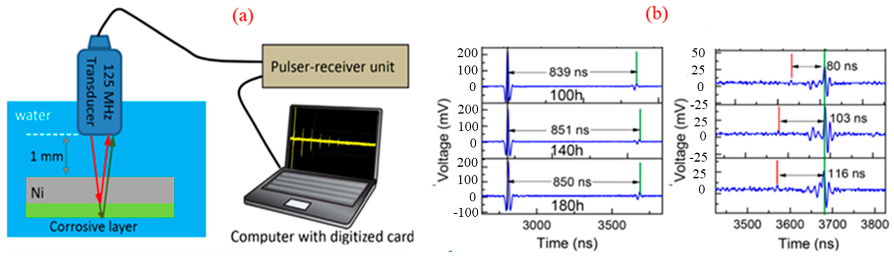
The fundamental principle of the ultrasonic monitoring method is to generate mechanical waves or vibrations in tested samples in experimental laboratories or actual environments [8,39], as shown in Figure 1a. Ultrasound is generated and received in different ways. The most common method of generating and receiving ultrasonic waves is piezoelectric transducers, which are transmitted to the tested material through an acoustic coupler, while electromagnetic acoustic transducers generate waves directly in the tested material [29]. Ultrasound is highly sensitive to structural damage and has high permeability to materials. The second harmonic provides valuable information about material damage conditions by measuring the amplitude ratio of the fundamental and second harmonics [40,41]. In some countries, ultrasonic monitoring has been used as a standardized evaluation method for compressive strength and material crack depth [30]. When conducting large-scale corrosion monitoring on the high-temperature pipes of thermal power plants and oil pipelines, ultrasonic monitoring can accurately and quickly determine where corrosion occurs. Using guided ultrasound in these situations has the following advantages: fast response speed, high sensitivity in detecting minor defects, and suitability for large-scale and long-distance testing [30,42]. Meanwhile, ultrasonic monitoring can be directly performed outside the component without using probes in contact with the corrosive environment during the testing process, so it is non-invasive to closed containers [43].
The commonly used monitoring methods based on ultrasonic testing techniques include contact piezoelectric transducers [44], lasers [45], and capacitance techniques. Contact piezoelectric transducers have low operating costs but higher requirements on the polishing degree of the contact surface to ensure good contact between the detection element (the transducer) and the sample surface. Unfortunately, this technique is unsuitable for harsh environments with high temperatures, high pressure, and strong corrosivity. Another method, the ultrasonic laser wave method, can somewhat compensate for these shortcomings. The advantage of the ultrasonic laser is that it can measure without sample contact and allows for point detection. It still has high-resolution scanning ability when working under high temperatures and pressure [46,47]. However, this test requires a sufficiently high surface finish of the sample [48]. Therefore, the signal-to-noise ratio is high. The third ultrasonic method, the capacitive ultrasonic transducer, has high sensitivity and can measure the absolute displacement of first and second harmonics. However, sample preparation is cumbersome [30,49].
Liu et al. [50] introduced the use of the piezoelectric pulse-echo method in corrosion monitoring. As shown in Figure 1a, the ultrasonic signal travels through the water medium, is then reflected by the specimen, and is finally received by the transducer. The typical time-domain signals from piezoelectric pulse-echo measurements of high-temperature nickel-based alloys with different corrosion layer thicknesses are displayed in Figure 1b. The signal is offset to compare the thickness of varying corrosion layers. The green line represents the reflectivity of the pipe back, while the red line represents that of the internal interface.
![Applsci 14 02350 g001]()
Figure 1.
Schematic diagram of the device and principle for ultrasonic measurement (a) and typical results (b) Reprinted from Ref. [50]. 2018, Elsevier.
Figure 1.
Schematic diagram of the device and principle for ultrasonic measurement (a) and typical results (b) Reprinted from Ref. [50]. 2018, Elsevier.
2.2. Infrared Thermography Method
Temperature is one of the most common indicators to measure the health status of equipment and components [32,51,52], and based on this, the infrared thermal (IRT) imaging technique has been developed. It provides a reliable, fast, direct evaluation method with a broad response range. It uses infrared imaging systems (such as infrared cameras) to record electromagnetic waves emitted by objects and establish a clear relationship between temperature and material corrosion defects [53]. The advantages of IRT are as follows: as a non-invasive technique, IRT does not affect the target [51,54] and can safely monitor very high temperatures or dangerous objects [54]; IRT provides two-dimensional images for comparison of different regions of the target [54]; IRT is an online (real-time) monitoring technique that can achieve large-scale real-time monitoring (with the help of advanced image processing techniques) [32,54,55].
Thermal imaging techniques can be divided into two categories: active and passive. In active thermal imaging, in addition to a thermal imager, an external excitation source is also needed to stimulate the thermal evolution inside the object during heating or cooling. On the contrary, passive thermal imaging does not require an external stimulus source because the object is at a temperature naturally different from the background (such as the human body). Passive thermal imaging is more commonly considered a qualitative method for identifying abnormal temperature patterns. Worthy of special description, it is the particular controlled requirements of the active thermal imaging method, including the amount and form of stimulation, that enable it to allow for not only the identification of defects but also quantitative analysis of anomalies, such as the characterization of the physical and thermal characteristics of defects. The excitation mechanisms in active imaging techniques mainly include optical thermography, laser thermography [56], induction thermography [57], vibrothermography [58], and microwave thermography [59,60].
Metal defect size, defect depth recovery/reconstruction, and defect thermal characteristics, such as thermal diffusivity, are considered quantitative IRT methods for evaluating corrosion and metal loss [32]. During the analysis and processing of corrosion data measured by IRT, thermal contrast calculation is the most commonly used method to improve the visibility of subsurface defects. Among them, absolute temperature contrast is achieved by assigning color or intensity to each infrared energy level corresponding to electromagnetic flux or exact temperature (through radiometry), converting images obtained using infrared cameras into visible images (heat maps) [54]. Absolute thermal comparison requires consideration of two critical assumptions. Firstly, we need to understand the sound field’s position within the field of view of an infrared camera; secondly, we need to consider that thermal stimulation is uniform on the sample. To address the testing limitations brought by these two hypotheses, Pilla et al. proposed a modified version of absolute thermal contrast, named differential absolute contrast (DAC). In addition, the analysis methods for IRT results also include temperature signal reconstruction (TSR) using temperature and contrast derivatives, statistical techniques, matrix factorization, phase-sensitive techniques, and artistic intelligence-based techniques. Please refer to [32] for detailed information.
As for the IRT mechanism exhibited in Figure 2, the total radiation received by the camera comes from three typical sources: emission from the target object (Eobj), emission and reflection from the surrounding environment (Erefl), and emission from the atmosphere (Eatm). However, since not all received radiation comes from the target object, to accurately measure temperature, it is necessary to compensate by removing radiation from other sources (such as surrounding objects or the atmosphere) when converting to temperature [54].
IRT can also detect water inclusion defects in composite sandwich structures. Figure 3 shows the effective detection of water corresponding to colder surface areas in the actual rudder of an aircraft by IRT. Thermal imaging can detect the phase change energy required for melting and infiltrating water, as it generates temperature changes.
2.3. Microwave Imaging
Microwave non-destructive testing is based on the interaction between microwaves and dielectric materials. The frequency range of employed microwaves is generally 5–50 GHz. At this frequency range, defects or structural abnormalities in the material can cause enough changes in dielectric property. With the help of corresponding analysis software, this dielectric difference can be converted into readable voltage values, which can then be restored to images of internal defects and structures through specific algorithms. The schematic diagram of the microwave detection is shown in Figure 4a, taking one steel plate covered by coating as an example. The near-field of an open waveguide illuminates the incident signal. It is transmitted into layered media (the coatings and the steel plate substrate) and reflected by conductive plates. The ratio of these two signals gives the effective reflection coefficient of the tested sample [61].
The microwave transmitter inside the energy emission device emits the selected microwave signal within a specific frequency range, ensuring the microwave propagates in the tested dielectric material. Different dielectric characteristics will reflect changes in the material structure or internal defects. These subtle differences can cause changes in the amplitude and phase of the reflected microwaves. The receiving sensor within the measurement unit can recognize and collect the performance parameters of the reflected waves and perform real-time analysis and calculation, ultimately displaying real-time images of the dielectric material’s internal structure and defect morphology, as given in Figure 4b,c. Microwaves can effectively penetrate dielectric materials, and any small discontinuity in the material can cause changes in its dielectric properties. Microwaves are very sensitive to changes in dielectric properties, so they have a very high detection sensitivity for any slight defects in dielectric materials [62].
The microwave non-destructive monitoring supports remote detection, estimates defects’ physical size and direction, and is easy to operate [63,64]. Microwave NDT techniques may be the unique solution in some situations (such as high temperature applications) [61]. Near-field open waveguide non-destructive microwave imaging seems to be one of the most promising techniques for detecting the presence of a particular layer or internal defects in layered structures [61,65]. In recent years, microwave non-destructive testing (MNDT) has significant potential in determining the properties of concrete, as it is highly effective in detecting pores, cracks, unevenness, and defects [33].
The main application of microwave imaging techniques in metal corrosion monitoring is as follows: a waveguide probe with primary mode excitation is used to irradiate structures with electromagnetic waves in the proper frequency range. The amplitude and phase difference between the reflection coefficients of non-coated and coated samples are related to the tested layer thickness and dielectric constant. Generally, there is a significant difference in attenuation and reflection signals between the defect and non-defect areas. The differential characteristics recorded in the reflection signal are employed to detect and determine the defect size of the tested sample. The calculation of reflection coefficients for various media mainly includes deriving the forward and backward propagating electric and magnetic field components in each layer based on the known incident field and applying appropriate boundary conditions at each interface. These complex reflection coefficients refer to the complex number of spectral changes in their phase and amplitude. The measurement data will provide information about the location and size of defects [66]. This highly sensitive interaction is a function of defect size and position within the waveguide aperture [61].
2.4. Eddy Current Detection
Eddy current testing (ECT) is based on the interaction between the main magnetic field and the tested material to generate eddy currents within the specimen [67,68]. Discontinuity features such as corrosion and material loss can be detected by monitoring changes in coil impedance or measuring induced magnetic fields [36,67,69]. The significant advantage of ECT is that it can detect defects under high-temperature conditions, and its probes can be made into various shapes to adapt to different objects. However, the ECT detection of deeper defects within the material substrate still faces issues of lower penetration depth and skin effects of ferromagnetic materials [35]. Traditional ECT works at a single frequency, where a sine wave drives the excitation coil, of which the application, in the case of non-conductive composite materials, may be limited by penetration depth due to the impact of delamination on the signal-to-noise ratio [70,71]. Typical eddy current probes include impedance change probes and excitation detection probes. Several commercial probes, such as absolute and differential tube probes, electric rotary probe coils, and array probes, have been widely used for pipeline detection [72]. ECT has several advantages: (1) non-contact detection can penetrate the coating layer without coupling medium; (2) defects can be detected under the condition of high temperatures, and the probe of ECT can be made into various shapes to adapt to different objects; (3) it has a higher sensitivity to near-surface defects [35].
The general schematic of the pulse eddy current (PEC) system is depicted in Figure 5a, by which Yunze He et al. [73] investigated the corrosion problem of soft steel (S275). The PEC response caused by corrosion is a complex combination of many factors. The two time-domain features extracted from the PEC response, representing the changes in conductivity and permeability of the corrosion layer or actual corrosion area, are generally used to characterize corrosion behavior. Additionally, the relationship between PEC characteristics and exposure time, which can be used for measuring corrosion rate and early corrosion assessment and prediction, has been derived. The experimentally obtained values and fitting lines of PV (Bnorm) for uncoated and coated samples are shown in Figure 5b [73]. The measurements at different exposure times were performed under the same excitation, taking the average measured results as the experimentally obtained values.
2.5. Acoustic Emission
Acoustic emission (AE) refers to the phenomenon where a material emits transient sound waves locally due to the rapid release of energy. The deposition of corrosion products, the rupture of passivation films, and the initiation and propagation of cracks all generate AE signals with different characteristic parameters [38,74]. Therefore, based on this information, the occurrence time, starting sites, and severity of corrosion damage can be determined. The application of acoustic emission techniques in electrochemical corrosion research has a history of more than 40 years, with existing research mainly focusing on monitoring acoustic emission signals during the electrochemical corrosion processes to determine the corrosion locations and degrees.
Actually, during the electrochemical corrosion process, the generation and movement of hydrogen gas, stress changes of the metal surface, deposition of corrosion products, rupture of passivation films or salt layers, and oxygen reduction may all be sources of acoustic emission. Meanwhile, it is necessary to establish the relationship between acoustic emission signals and electrochemical corrosion rate, corrosion potential, etc. Based on this, it is possible to identify the characteristic acoustic emission signals in the electrochemical corrosion process and clarify the corresponding physical correspondence [75]. The application of AE in the on-site measurement of small-diameter drilling processing status is shown in Figure 6.
However, the difficulty in AE monitoring under normal and high-temperature conditions is how to analyze the signal. The diversity of AE sources and the suddenness and uncertainty of signals pose significant challenges to analyzing AE data and establishing corresponding relationships between AE signals and corrosion behavior. In addition, attenuation of sound signals, reflection of sound waves, mode conversion, structural correlations or discontinuities, and interference from background noise can all hinder the analysis of AE signals [77]. Currently, the commonly used AE analysis method is parameter analysis. Various signal processing techniques, such as wavelet analysis, modern spectral analysis, and neural network analysis, have been successfully applied. The development of modal AE theory and related techniques has provided a new way to further explain AE signals’ physical meaning [75].
AE has been used to monitor the coupled environmental cracking process in high-temperature and high-pressure water environments [78,79]. Yuyama et al. [80] believe that compared to room temperature, the oxide film formed on the surface of materials in high-temperature and high-pressure water environments is thicker and that the amplitude of AE signals generated by crack initiation and propagation is relatively higher, making it possible to monitor cracks. Alekseev et al. [81] investigated the sensitivity of various materials to SCC in chloride-containing environments at 300–320 °C and 70–80 MPa via AE. They indicate that the combination of the event count and amplitude of AE signals can determine cracks’ initiation and instability. Cassagne et al. [82] conducted a similar study on nickel-based alloy 600 in a simulated PWR environment (290–330 °C) but used characteristic parameters such as the AE signal’s amplitude, energy, and rise time. Máthis et al. [78] and Xu Jian et al. [79,83] studied the SCC process of solid solution and sensitized 304SS in high-temperature and high-pressure water. The AE signals generated during the transgranular SCC process include sudden and continuous types, with corresponding AE sources being crack propagation and plastic deformation [78,83]. However, only continuous AE signals are generated during the intergranular SCC process, corresponding to plastic deformation [79]. Although some studies suggest that AE is highly sensitive to the very early stages of crack development in high-temperature water, there are few related studies [84].
Various other non-invasive corrosion monitoring technologies are also widely used in engineering practice. Multi-frequency electromagnetic sensors, consisting of a transmitter and receiver coil, can be used for the corrosion and integrity detection of oil pipelines. Due to the skin effect, low-frequency electromagnetic scanning can calculate the thickness of pipeline metal, while high-frequency electromagnetic scanning can detect the characteristics of the inner wall [44]. Optical fiber sensors (OFS) are also small, flexible, lightweight, susceptible, and compatible with fiber optic data communication networks, which can measure corrosion in several areas within a single optical channel. Passive radio-frequency identification (RFID) sensors, especially chipless passive RFID sensors, are a comprehensive wireless sensor family for pipeline corrosion, with low cost, compact size, lightweight, and remote sensing [8]. These non-destructive monitoring techniques are primarily based on physical methods, which monitor the contour, depth, and other characteristic information of the corrosion layer online and, to some extent, provide information on alloy corrosion behavior. They have broad application prospects in the corrosion monitoring of pipes and equipment exposed to sub-/supercritical water systems. Please see the literature for more detailed information on non-destructive monitoring techniques for alloy corrosion [8,85].
3. Invasive Corrosion Monitoring Techniques
The electrochemical online corrosion monitoring technique has the characteristics of high sensitivity, fast response speed, stable long-term service, a simple process, and low cost. It can accurately determine the corrosion rate and form of materials and achieve automatic feedback control at industrial sites. More importantly, based on alloys’ electrochemical corrosion data, corrosion rate prediction, stress corrosion cracking evaluation, and other related determinations can be carried out. Electrochemical corrosion monitoring methods have broad application prospects in complex extreme sub-/supercritical water environments, such as higher temperatures, pressures, and high content of salts and dissolved oxygen; occurrence in cooled-water nuclear power plants; and advanced supercritical water treatment equipment.
3.1. Electrical Resistance Probe
The electrical resistance probe technique obtains corrosion loss and corrosion rate data by measuring the resistance change of metal specimens. The corrosion products of metals, such as metal oxides, are mostly non-conductive. If current is applied to a metal sheet, as corrosion progresses, the thickness of the metal sheet will decrease, increasing electrical resistance. The corrosion rate can be obtained after extending the information on resistance variation over time to the relationship between material thickness and corrosion time. This type of resistance probe is also known as an electronic mount [86,87].
As shown in Figure 7, during the monitoring process, one side of the metal specimen is exposed to the environment t, and a current goes through the metal specimen. The electrical resistance of the metal specimen can be calculated as follows:
In the formula, ρ represents the conductivity of the metal test piece, A is the cross-sectional area of the metal piece, and l stands for the length.
Liu et al. [88,89] used an electrical resistance probe to study the corrosion of pipeline steels, as depicted in Figure 7. As corrosion progresses, by monitoring the change in resistance value, the change in corrosion thickness can be derived based on Formula (1), thereby obtaining information on corrosion loss and corrosion rate. The electrical resistance probe technique is available for measurement in liquid solutions (electrolyte or nonelectrolyte), gas environments, and other media. It has the characteristics of relatively simple operation, easy maintenance, and easy data analysis. Moreover, it can achieve real-time corrosion data collection and transportation. Compared with other monitoring methods, it is highly reliable and has a better economy, making it widely used in industries such as oil and gas production, pipelines, the chemical industry, cultural relic preservation, and power generation.
3.2. Electrochemical Corrosion Potential
When electrochemical corrosion is carried out on an isolated metal material, the cathodic and anodic reactions occur at the same potential, which is the mixed potential of these two electrode reactions coupled with each other. In corrosion electrochemistry, it is called the electrochemical corrosion potential (ECP) [90]. Since the corrosion of materials in aqueous solutions is essentially controlled by electrochemical processes, there is a specific correspondence between the ECP of materials and their corrosion behavior. Therefore, measuring ECP can be used to determine the corresponding corrosion status of materials, which can serve as a basis for adjusting environmental parameters and achieving the goal of controlling corrosion behavior. The measurement of ECP has no interference with the tested system and can perform in situ, non-destructive, long-term continuous measurement. Constructing an alarm system based on the changes in ECP signals is easy and suitable for on-site corrosion monitoring.
The ECP test results for two nickel-based alloys are shown in Figure 8 [91]. In fact, in most studies, the OCP test results are used to roughly represent the ECP values; the ECP described in Figure 8 is the OCP test result. Figure 8a shows that the corrosion potential of 690 and 800 alloys monotonically decreases with the increase in pressure at 25 °C. Figure 8b shows that at a constant pressure of 10.0 MPa, the self-correction potential of 690 and 800 alloys varies with temperature at different temperatures, which can be roughly divided into two temperature influence intervals. The first temperature influence interval is from 25 °C to 250 °C, and with the increase in temperature, the self-corrosion potential of 690 alloy and 800 alloy decreases almost linearly, with the second temperature range being 250 °C to 300 °C. The average self-corrosion potential of 690 alloy and 800 alloy is very similar.
The acquisition of ECP data requires using a potential meter with a high internal resistance (significantly greater than 106 Ω) to monitor the system composed of the working material to be tested and the stable reference electrode. As for the ECP of materials, it is usually necessary for guiding the polarization curve measurement, assisting the drawing of potential–pH diagrams (E–pH), as well as determining the critical or sensitive potential ranges for local corrosion behaviors, such as pitting corrosion, crevice corrosion, and stress corrosion cracking (SCC). Based on the mutual verification relationship between these electrical corrosion data, judging whether the material will undergo corrosion problems is convenient.
ECP monitoring at nuclear power plants is the most representative application. So far, ECP monitoring is the only method not requiring depressurization, current limiting, or cooling sampling to obtain in situ electrochemical information on the water chemistry and corrosion environment of advanced water-cooled nuclear reactors. Currently, ECP is mainly used as a data reference for the hydrogenation water chemistry of BWRs and PWRs and the oxygenation water chemistry of PWR secondary circuits in nuclear power corrosion monitoring [92]. Corrosion prevention and control can be achieved by adjusting the ECP below the SCC critical potential and to the stable range of the oxide film by combining the E-pH diagram [93,94].
Due to each nuclear power plant’s different operating environmental parameters, the consistency of ECP monitoring results is poor. Therefore, conducting online ECP monitoring at each nuclear power plant is necessary. However, there are still the following issues in the current ECP monitoring of nuclear power plants: (1) there is no mature high-temperature reference electrode that fully meets the long-term monitoring requirements; (2) due to the complex structure of nuclear power plants, the corrosion reactions occurring at different structural sites are also complex. The cost is high once the online ECP monitoring is performed on many sites.
The theoretical calculation of ECP can somewhat solve the complex, costly online monitoring problem. Christensen et al. [95], Dixon et al. [96], and Burn et al. [97] proposed a water radiolysis model that can calculate the concentrations of oxidation–reduction substances at selected locations inside nuclear power plants. Kim et al. [98] and Macdonald et al. [99,100] combined the water radiolysis model with the mixed potential model and then proposed a semi-empirical formula based on laboratory test results to calculate the ECP value of 304SS at a selected location inside the BWR reactor. Macdonald et al. [101] also extended the ECP calculation to PWR. However, due to the lack of primary thermodynamic data, there are currently no reports on ECP calculations for other materials, and the reliability of the calculated ECP values also needs to be verified.
3.3. Electrochemical Impedance Spectroscopy
Electrochemical impedance spectroscopy (EIS) is a frequency-domain data analysis that studies the variation of electrochemical impedance with frequency by applying a small-amplitude sinusoidal AC excitation signal when the electrochemical system is under a stable DC polarization condition. EIS measurement has a lower system disturbance and a wide testing frequency range. It can obtain in situ dynamics data on electrochemical processes and electrode interface structure information related to electrochemical corrosion without damaging the system. It is suitable for online corrosion monitoring. On the other hand, there is an approximate linear relationship between disturbance and the corresponding system, which can simplify the mathematical processing of test results. As a branch of the impedance spectroscopy technique, dynamic electrochemical impedance spectroscopy can obtain richer electrochemical information and has been used in the study of material passivation films [102].
Electrochemical impedance spectroscopy contains rich information on the microscopic mechanisms and microscale process dynamics behind electrochemical corrosion behavior [103,104]. However, most studies usually use the “direct equivalent circuit method” to analyze electrochemical impedance spectroscopy data, which can only obtain macroscopic values of equivalent circuit components in the corrosion system, such as resistance, capacitance, etc., and fail to provide microscale process information such as atomic-scale dynamics of alloy corrosion. Establishing an impedance mathematical model of the alloy matrix | passivation film system based on the corrosion microscale process is a crucial foundation for obtaining information on the corrosion microscale process by analyzing electrochemical impedance spectroscopy data. The Bode plots of several typical impedance spectrum test results are shown in Figure 9.
Ai et al. [107] and the authors of this paper [108,109] have employed the point defect models and the experimentally obtained EIS data to analyze the atomic scale corrosion anodic processes of some metals and alloys, such as zirconium alloy, stainless steel 304, and nickel-based alloy 600, under high-temperature conditions. For example, Ai et al. [107] pointed out that the rate constant of “the transformation from zirconium atom to the lattice zirconium within ZrO2” at the interface of the polycrystalline zirconium matrix/passivation film at 250 °C is 2.42 × 10⁻¹⁵ mol·cm−2·s−1, with a charge transfer coefficient of approximately 0.27. The authors’ previous research found that the growth of the barrier layer of the passivation film and the thickening of the film’s porous outer layer are determined by two atomic-scale processes at the interface between the passivation film and the substrate of stainless steel 304 in a PWR coolant simulation solution at 300 °C. They are, respectively, the process of the chromium-predominant metal atoms converting into lattice cations in chromium-rich oxides of the barrier layer and the transformation process of the iron-dominated metal atoms, which release electrons and enter the passivation film in the form of cation interstitials. The reaction rates are all approximately 10−11 mol·cm−2·s−1 and are influenced by water chemistry parameters such as pH value and dissolved oxygen content [109]. In the similar simulated solutions of the primary circuit coolant of PWRs, the rate of metal atom conversion to cations at the interface between the alloy substrate and the passivation oxide film for nickel-based alloy 600 is relatively lower, ranging from 1.5–4 × 10⁻¹² mol·cm−2·s−1, than that of the stainless steel 304 [108]. The relevant content, such as point defect theory and electrochemical impedance spectroscopy analysis, has been detailed in our previous articles [1,110] and will not be further elaborated here.
3.4. Electrochemical Noise
Electrochemical noise (EN) refers to the random non-equilibrium fluctuation phenomenon of electrochemical state parameters (such as electrode potential, external measured current density, etc.) during the evolution of electrochemical dynamic systems [111]. This fluctuation phenomenon provides rich evolutionary information for the system. The electrochemical noise technique has been widely applied in industrial electrochemistry, including metal corrosion and protection, chemical power supply, and metal electrodeposition [111,112]. As an in situ, online, and non-interference detection method, it can monitor the uniform and local corrosion of materials online and the type and strength of corrosion remotely [113].
When applying electrochemical noise techniques to monitor electrochemical corrosion in high-temperature water, attention is usually paid to corrosion potential or current noise. Monitoring the current noise usually involves connecting two working electrodes of the same material through a zero-resistance meter to monitor the coupling current between them. However, monitoring potential noise requires using reference or pseudo-reference electrodes, which face the same hardware limitations as ECP testing. In addition, the difficulty of applying EN in high-temperature water systems lies in how to reduce the internal noise of equipment to improve the accuracy and precision of data [84]. The key to successful monitoring is to use stable and reliable reference electrodes, ensure high conductivity of the test solution [114], and reduce the distance between the test electrode and the reference electrode to reduce background noise [115].
Figure 10 shows an example of EN monitoring results for Q235B steel exposed to the atmosphere of Tianjin city for 20 days [86]. When the humidity is low, the electrochemical current noise (ECN) and electrochemical potential noise (EPN) amplitudes are very small, with only a few nanoamps and millivolts, indicating a significantly lower corrosion rate. When the relative humidity increases to 65%, the fluctuation amplitude of ECN and EPN substantially increases, and the corrosion rate of Q235B steel correspondingly increases. The evolution of noise resistance (Rn) is closely related to humidity. As humidity rises, Rn values decrease accordingly; Rn increases correspondingly with the decrease in moisture [116].
On this basis, analyzing EN data and extracting feature information containing electrochemical processes is crucial. The analysis of EN data can usually be divided into two types: time-domain and frequency-domain. Time domain analysis is a visual inspection, image fitting process (transient analysis), or statistical analysis of the original EN data. The temporary shape contains basic information about electrochemical processes. Some characteristic parameters obtained from statistical analysis, such as standard deviation, root mean square value, skewness, local index, etc., can be used for qualitative evaluation of pitting, SCC, and crevice corrosion processes [117], and the obtained noise resistance can quantitatively evaluate corrosion rate [118]. Some studies use the Fast Fourier Transform (FFT) or Maximum Entropy method, converting the EN signal from a time domain to a frequency domain and obtaining the Fourier spectrum or power spectral density [119].
In 1968, Iverson observed, for the first time, the random fluctuation of corrosion electrode potential over time in a corrosion electrochemical system (i.e., electrochemical noise) [120]. In the last decade, the application of electrochemical noise techniques in corrosion science and related scientific fields has increasingly attracted widespread attention. In the study of the local corrosion of metals, electrochemical noise can be used to determine corrosion types and study pitting corrosion and stress corrosion cracking characteristics. At the same time, the electrochemical noise technique can also be applied to coating performance evaluation and corrosion inhibitor screening, providing a powerful technique for studying material corrosion problems, protection, and surgical support.
Some scholars at home and abroad have adopted electrochemical noise techniques to investigate corrosion issues in high-temperature and high-pressure water systems. Zhou et al. [121] found a linear relationship between the weight loss rate of 304SS in high-temperature water and the reciprocal of noise resistance, consistent with the research results in room-temperature systems. Macák et al. studied the corrosion behavior of 304SS [122] and 08CH18N10T steel [123] in high-temperature water. They found that during the initial soaking stage, the noise resistance increased first and finally became stable. The average corrosion rate calculated using the experimentally obtained noise resistance is consistent with the EIS results. Song Shizhe et al. [124] performed the EN monitoring for stainless steel and carbon steel pipelines in the laboratory and industrial sites. They found that as the temperature increased, the measured noise resistance showed a decreasing trend, and the value of the noise resistance corresponded to the rust on the surface of the pipeline. Another critical piece of research in the exploratory stage focuses on the online monitoring of EN signals for environmentally assisted cracking. Preliminary research has indicated that electrochemical noise signals are more sensitive to crack propagations, during which both the current signal’s increase and the voltage signal’s decrease can be monitored simultaneously [125,126]. If the crack propagation is discontinuous, a potential reduction with a long time interval will occur, accompanied by a significant increase in current. Suppose the crack rapidly expands and the surface oxide film does not have time to undergo re-passivation. In that case, it will decrease the potential signal and cause a continuous increase in the current signal [126]. However, due to the weak noise signals generated during the initiation and early propagation stages of cracks and the high interference of background noise, it is challenging to study the initial stage of environmentally assisted cracking using the EN technique.
3.5. Research Platform of In Situ Electrochemical Corrosion Testing
To investigate the electrochemical corrosion of alloys in high-temperature and high-pressure water systems, it is necessary to establish a research platform for simulating experimental environments. MacDonald and his group have extensively researched high-temperature electrochemical corrosion [127,128,129,130]. They have designed the circulating flow loop with a hydrodynamic autoclave vessel, as shown in Figure 11, which contains the storage tank, a high-pressure positive displacement pump (2 L/h capacity pulsating diaphragm pump), a hydraulic accumulator, a regenerative heat exchanger (cooled by freshwater), and so on. The circulating flow loop with a hydrodynamic autoclave can continuously update the solution in the reactor, keep the simulated solution in the testing area fresh, and avoid the interference of impurities and salt deposition during long-term experimental processes. Due to the existence of circulating loops, the reactor’s design requirements and production costs are reduced. In addition, the circulating flow loop with a hydrodynamic autoclave designed in the research platform is consistent with most engineering practical application scenarios. The reference electrode is the core component of the electrochemical research platform, which mainly includes various reference electrodes such as hydrogen electrodes, YSZ electrodes, metal/metal oxide electrodes, external pressure balance reference electrodes, etc., especially the YSZ electrode, which has been successfully applied in high-temperature conditions exceeding 500 °C [1,106]. These contents are extensive and complex and will be further explored in another review article.
Based on the research platform established by Macdonald’s group, researchers from the Institute of Metals (IMR) in the Chinese Academy of Sciences have developed a high-temperature electrochemical research platform that can monitor and control water quality, as shown in Figure 12. Two refreshed autoclaves were connected in series in the loop, with autoclave 1 arranged in the upstream section. Both autoclaves are made of stainless steel and have a 2 L volume. Autoclave 1 is lined with pure Ni, while autoclave 2 is not. These two autoclaves could be used collectively or solely during the exposure experiments. The inlet and outlet water chemistry parameters, namely dissolved oxygen concentration (DO) and conductivity, were monitored with METTLER TOLEDO Thornton Model 3X7-210 (METTLER TOLEDO, Zurich, Switzerland) dissolved oxygen sensors and Model 240-201 conductivity sensors, respectively. A computer with Labview 8.5 software was used to control temperature and DO. Temperature fluctuations in both autoclaves were controlled well within ±0.5 °C, and DO fluctuation in inlet water was within ±10 ppb (by weight) [131,132,133].
Huang et al. investigated the corrosion electrochemical characteristics of nickel-based alloy 690 using the research platform, as shown in Figure 13 [134]. Figure 13a shows potentiodynamic polarization curves for Alloy 690 at 300 °C in 1500 ppm B and different concentrations of Li solutions without Zn injection. As the pH value increases, the electrochemical corrosion potential sharply decreases, and the passivation current density slightly decreases. This indicates that the 690 alloy forms an oxide film in all pH solutions studied and exhibits good corrosion resistance in alkaline solutions. Figure 13b shows the polarization curves of 690 alloy in solutions with different zinc concentrations at 300 °C, indicating an increase in zinc concentration enhances corrosion resistance. The passivation current density is 10−4 A·cm−2.
Li et al. from Xi’an Jiaotong University (XJTU) developed a new generation of multi-functional electrochemical research platforms, as shown in Figure 14 [135]. It comprises a high-pressure gas injection circuit, a low-pressure gas dissolution control circuit, a sub-/supercritical hydrochemical research device, and a sub-/supercritical water primary circuit. By comparison, this system directly introduces the target gas into the reactor through a liquid gas tank, which can effectively increase the upper limit of the dissolved gas concentration in the solution and is suitable for studying the effect of high-concentration liquefied gas on the electrochemical corrosion behavior of materials. Meanwhile, high concentrations of dissolved gases are beneficial for electrochemical catalytic synthesis. On the other hand, the combination of wire-through-type high-temperature sealing components, high-temperature insulation sealing materials, threaded connections, and welding can achieve sealing and insulation between the electrode and the reactor under high-temperature and high-pressure conditions. The hanging connection method improves the flexibility of the electrode and makes it less susceptible to mechanical impact damage.
Yang and Li et al. [136] obtained the electrochemical corrosion data of nickel-based alloy 690 samples in simulated primary coolants of PWRs at temperatures of 200–300 °C. The simulated primary coolant is a lithium borate solution with a dissolved oxygen concentration of 400 ppb, 2000 ppm B, and 2 ppm Li. As shown in Figure 15, as the experimental temperature increases, the open circuit potentials of alloy 690 decrease from −0.553 VSHE to −0.783 VSHE. On the other hand, the current density is independent of the formation potential of the passivation film at the same temperature. In addition, the study also tested the electrochemical impedance spectrum at open circuit potentials, and the results showed that the absolute value of impedance decreased with increasing temperature, indicating a decrease in overall corrosion resistance. This is consistent with the current behavior of passivation.
In summary, the current research apparatus used for electrochemical testing in high-temperature and high-pressure water systems are mainly the continuous flow platforms established by scholars represented by McDonald. New platforms are upgraded and rebuilt based on them. These continuous platforms solve the problems of solution contamination and salt deposition in sequential batch platforms. They are often used to simulate the corrosion problem of the primary circuit of PWRs. However, due to the issue of electrode sealing insulation, it is challenging to apply it to tests above 300 °C. The newly established platform developed by Li’s team at Xi’an Jiaotong University based on McDonald’s design concept can meet the higher temperature requirements of 550 °C and achieve a wide adjustable content range of interested dissolved gases in the system [137]. In addition, the research platform based on tube furnaces designed by Sen Lin et al. introduces a new electrode installation and sealing method, which can further increase the operating temperature to 700 °C [138].
4. Conclusions
Subcritical/supercritical water is widely employed in energy and environmental fields. The extremely high temperature and high-pressure hydrochemical conditions, coupled with the possible existence of corrosive species such as dissolved oxygen and various inorganic salts, pose significant challenges to developing, designing, and safely operating various subcritical/supercritical water-related equipment due to corrosion. Studying and controlling the corrosion behavior of typical materials in sub-/supercritical water systems is the key to solving the corrosion problem, especially when performing in situ corrosion monitoring. It helps capture real-time corrosion information and promptly adjust relevant equipment parameters for corrosion control. It also provides accurate data references for optimizing and improving various corrosion prediction models.
This paper first comprehensively introduces the fundamentals, advantages and disadvantages, and applications of several non-invasive in situ monitoring technologies, such as ultrasonic measurement, infrared thermal imaging, microwave monitoring, eddy current detection, and acoustic emission, which can be used in a wide temperature range and can be employed as portable corrosion monitoring instruments in practical engineering applications. Additionally, considering the importance of electrochemical corrosion in the study of corrosion mechanisms and prediction of corrosion behavior in sub-/supercritical water systems, invasive in situ electrochemical testing methods, including electrochemical corrosion potential, electrochemical impedance spectroscopy, and electrochemical noise, are also discussed in detail. The typical existing electrochemical research platform for sub- and supercritical aqueous systems can achieve in situ online water chemistry monitoring and regulation. Some new electrode installation methods, such as using pyrophyllite for sealing and the hanging connection, may elevate the operating temperature up to 700 °C, providing fresh ideas for upgrading and renovating existing mainstream research platforms.
Author Contributions
Z.B. and Y.L. contribute equally. Conceptualization, Y.L. and Z.B.; Investigation, Z.B., L.X., Q.Z. and S.D.; writing—original draft preparation, Y.L., Z.B. and Y.Z.; writing—review and editing, Y.L., P.G. and Z.Y.; visualization, Z.B. and L.X.; supervision, Y.L.; funding acquisition, Y.L. and D.X. All authors have read and agreed to the published version of the manuscript.
Funding
This work is supported by the National Natural Science Foundation of China (22378322, 22008190), the Key Research and Development Program of Shaanxi (2024GX-YBXM-425), the China Postdoctoral Science Foundation (2022M722526), the Fundamental Research Funds for the Central Universities (xtr052022009), and the National Key Research and Development Program of China (2021YFE0104900).
Conflicts of Interest
The authors declare no conflicts of interest.
References
- Li, Y.; Bai, Z.; Ding, S.; Macdonald, D.D.; Qiu, J.; Wang, K.; Jiang, Z.; Wang, S. Electrochemical techniques and mechanisms for the corrosion of metals and alloys in sub- and supercritical aqueous systems. J. Supercrit. Fluids 2023, 194, 105835. [Google Scholar] [CrossRef]
- Wang, Y.; Oshima, Y.; Akizuki, M. Catalytic Performance of Solid Base Na-ZrO2 in Subcritical Water. J. Chem. Eng. Jpn. 2024, 57, 2293044. [Google Scholar] [CrossRef]
- Ehrlich, K.; Konys, J.; Heikinheimo, L. Materials for high performance light water reactors. J. Nucl. Mater. 2004, 327, 140–147. [Google Scholar] [CrossRef]
- Han, J.; Kim, S.; Kim, S.J.; Lee, Y.K.; Hur, D.H. Fouling behavior of a printed circuit steam generator under simulated operating conditions of a small modular reactor. Ann. Nucl. Energy 2022, 173, 109127. [Google Scholar] [CrossRef]
- Macdonald, D.D.; Urquidi-Macdonald, M. The Electrochemistry of Nuclear Reactor Coolant Circuits. In Encyclopedia of Electrochemistry; Wiley-VCH Verlag GmbH & Co. KGaA: Weinheim, Germany, 2007. [Google Scholar]
- Xiong, X.; Liu, X.; Tan, H.; Deng, S. Investigation on high temperature corrosion of water-cooled wall tubes at a 300 MW boiler. J. Energy Inst. 2020, 93, 377–386. [Google Scholar] [CrossRef]
- Sun, X.; Ning, Y.H.; Yang, J.; Zhao, Y.; Yang, Z.J.; Zhou, X.Z. Study on high temperature corrosion mechanism of water wall tubes of 350 MW supercritical unit. Eng. Fail. Anal. 2021, 121, 105131. [Google Scholar] [CrossRef]
- May, Z.; Alam, M.K.; Nayan, N.A. Recent Advances in Non-destructive Method and Assessment of Corrosion Undercoating in Carbon-Steel Pipelines. Sensors 2022, 22, 6654. [Google Scholar] [CrossRef]
- Solovyeva, V.A.; Almuhammadi, K.H.; Badeghaish, W.O. Current Downhole Corrosion Control Solutions and Trends in the Oil and Gas Industry: A Review. Materials 2023, 16, 1795. [Google Scholar] [CrossRef]
- Jack, T.A.; Szpunar, J. Effect of Nb-induced microstructure on pipeline steel corrosion and stress corrosion cracking performance in acidic environment. Corros. Sci. 2023, 218, 111196. [Google Scholar] [CrossRef]
- Finsgar, M.; Jackson, J. Application of corrosion inhibitors for steels in acidic media for the oil and gas industry: A review. Corros. Sci. 2014, 86, 17–41. [Google Scholar] [CrossRef]
- Li, X.; Zhang, D.; Liu, Z.; Li, Z.; Du, C.; Dong, C. Share corrosion data. Nature 2015, 527, 441–442. [Google Scholar] [CrossRef] [PubMed]
- Li, Y.H.; Wang, S.Z.; Xu, T.T.; Li, J.N.; Zhang, Y.S.; Xu, T.T.; Yang, J.Q. Novel designs for the reliability and safety of supercritical water oxidation process for sludge treatment. Process Saf. Environ. Prot. 2021, 149, 385–398. [Google Scholar] [CrossRef]
- Kritzer, P. Corrosion in high-temperature and supercritical water and aqueous solutions: A review. J. Supercrit. Fluids 2004, 29, 1–29. [Google Scholar] [CrossRef]
- De Souza, G.B.M.; Pereira, M.B.; Mourao, L.C.; dos Santos, M.P.; de Oliveira, J.A.; Garde, I.A.A.; Alonso, C.G.; Jegatheesan, V.; Cardozo-Filho, L. Supercritical water technology: An emerging treatment process for contaminated wastewaters and sludge. Rev. Environ. Sci. Bio/Technol. 2022, 21, 75–104. [Google Scholar] [CrossRef]
- Marrone, P.A. Supercritical water oxidation-Current status of full-scale commercial activity for waste destruction. J. Supercrit. Fluids 2013, 79, 283–288. [Google Scholar] [CrossRef]
- Li, Y.; Ding, S.; Bai, Z.; Wang, S.; Zhang, F.; Zhang, J.; Xu, D.; Yang, J. Corrosion characteristics and mechanisms of typical iron/nickel-based alloys in reductive supercritical water environments containing sulfides. J. Supercrit. Fluids 2022, 187, 105599. [Google Scholar] [CrossRef]
- Wang, L.; Li, H.; Liu, Q.; Xu, L.; Lin, S. Effect of sodium chloride on the electrochemical corrosion of Inconel 625 at high temperature and pressure. J. Alloys Compd. 2017, 703, 523–529. [Google Scholar] [CrossRef]
- Tang, X.; Wang, S.; Qian, L.; Ren, M.; Sun, P.; Li, Y.; Yang, J. Corrosion Properties of Candidate Materials in Supercritical Water Oxidation Process. J. Adv. Oxid. Technol. 2016, 19, 141–157. [Google Scholar] [CrossRef]
- Guo, S.; Xu, D.; Li, Y.; Guo, Y.; Wang, S.; Macdonald, D.D. Corrosion characteristics and mechanisms of typical Ni-based corrosion-resistant alloys in sub- and supercritical water. J. Supercrit. Fluids 2021, 170, 105138. [Google Scholar] [CrossRef]
- Guo, S.; Xu, D.; Liang, Y.; Gong, Y.; Li, Y.; Yang, J. Corrosion characterization of ZrO2 and TiO2 ceramic coatings via air plasma spraying on 316 stainless steel in oxygenated sub- and supercritical water. J. Supercrit. Fluids 2020, 157, 104716. [Google Scholar] [CrossRef]
- Shome, A.; Das, A.; Borbora, A.; Dhar, M.; Manna, U. Role of chemistry in bio-inspired liquid wettability. Chem. Soc. Rev. 2022, 51, 5452–5497. [Google Scholar] [CrossRef]
- Qian, H.; Xu, D.; Du, C.; Zhang, D.; Li, X.; Huang, L.; Deng, L.; Tu, Y.; Mol, J.M.C.; Terryn, H.A. Dual-action smart coatings with a self-healing superhydrophobic surface and anti-corrosion properties. J. Mater. Chem. A 2017, 5, 2355–2364. [Google Scholar] [CrossRef]
- Wu, B.; Zhang, Y.; Meng, F.; Zhang, Z.; Li, Y.; Wang, J.; Han, E.-H.; Ming, H. Insights into stress corrosion cracking in scratched area of alloy 690TT steam generator tubes. Acta Mater. 2023, 255, 119083. [Google Scholar] [CrossRef]
- Gholamzadeh, H.; Shaik, A.; Daub, K.; Topping, M.; Daymond, M.R.; Persaud, S.Y. A mechanistic study on dealloying-induced stress corrosion cracking of Alloy 800 in boiling caustic solutions. Corros. Sci. 2023, 220, 111284. [Google Scholar] [CrossRef]
- Wang, X.; Shang, C.; Li, Z.; Bai, Y.; Liu, T.; Lu, Y.; Shoji, T. Study on the SCC behavior induced by creep cavities on scratched surface of Alloy 690TT in high temperature water. Corros. Sci. 2022, 196, 110017. [Google Scholar] [CrossRef]
- Li, J.; Cao, T.; Zhang, C.; Cheng, C.; Zhao, J. Failure analysis of reheater tubes in a 350 MW supercritical circulating fluidized bed boiler. Eng. Failure Anal. 2022, 137, 106285. [Google Scholar] [CrossRef]
- Xiong, X.; Chen, F.; Li, L.; Tan, H. Water Wall Tubes’ High Temperature Corrosion Root Cause Investigation: A 300 MW Level Boiler Case. Energies 2023, 16, 1767. [Google Scholar] [CrossRef]
- Honarvar, F.; Varvani-Farahani, A. A review of ultrasonic testing applications in additive manufacturing: Defect evaluation, material characterization, and process control. Ultrasonics 2020, 108, 106227. [Google Scholar] [CrossRef]
- Marcantonio, V.; Monarca, D.; Colantoni, A.; Cecchini, M. Ultrasonic waves for materials evaluation in fatigue, thermal and corrosion damage: A review. Mech. Syst. Signal Process. 2019, 120, 32–42. [Google Scholar] [CrossRef]
- Liu, W.; Hou, B.P.; Wang, Y.X.; Yao, Y.; Zhou, L. Sparse Structural Principal Component Thermography for Defect Signal Enhancement in Subsurface Defects Detection of Composite Materials. J. Non-Destr. Eval. 2022, 41, 8. [Google Scholar] [CrossRef]
- Doshvarpassand, S.; Wu, C.Z.; Wang, X.Y. An overview of corrosion defect characterization using active infrared thermography. Infrared Phys. Technol. 2019, 96, 366–389. [Google Scholar] [CrossRef]
- Wahab, A.; Aziz, M.M.A.; Sam, A.R.M.; You, K.Y.; Bhatti, A.Q.; Kassim, K.A. Review on microwave non-destructive testing techniques and its applications in concrete technology. Constr. Build. Mater. 2019, 209, 135–146. [Google Scholar] [CrossRef]
- Mazzinghi, A.; Freni, A.; Capineri, L. A microwave non-destructive testing method for controlling polymeric coating of metal layers in industrial products. NDT&E Int. 2019, 102, 207–217. [Google Scholar] [CrossRef]
- Xie, L.; Gao, B.; Tian, G.Y.; Tan, J.D.; Feng, B.; Yin, Y. Coupling pulse eddy current sensor for deeper defects NDT. Sens. Actuator A 2019, 293, 189–199. [Google Scholar] [CrossRef]
- Grosso, M.; Pacheco, C.J.; Arenas, M.P.; Lima, A.H.M.; Margarit-Mattos, I.C.P.; Soares, S.D.; Pereira, G.R. Eddy current and inspection of coatings for storage tanks. J. Mater. Res. Technol. 2018, 7, 356–360. [Google Scholar] [CrossRef]
- Erlinger, T.; Kralovec, C.; Schagerl, M. Monitoring of Atmospheric Corrosion of Aircraft Aluminum Alloy AA2024 by Acoustic Emission Measurements. Appl. Sci. 2023, 13, 370. [Google Scholar] [CrossRef]
- May, Z.; Alam, K.; A’In, N.; Rahman, A.; Nayan, N.A. Denoising of Hydrogen Evolution Acoustic Emission Signal Based on Non-Decimated Stationary Wavelet Transform. Processes 2020, 8, 1460. [Google Scholar] [CrossRef]
- Kowalczyk, J.; Josko, M.; Wieczorek, D.; Sedlak, K.; Nowak, M. The Influence of the Hardness of the Tested Material and the Surface Preparation Method on the Results of Ultrasonic Testing. Appl. Sci. 2023, 13, 9904. [Google Scholar] [CrossRef]
- Ruiz, A.; Ortiz, N.; Medina, A.; Kim, J.Y.; Jacobs, L.J. Application of ultrasonic methods for early detection of thermal damage in 2205 duplex stainless steel. NDT&E Int. 2013, 54, 19–26. [Google Scholar] [CrossRef]
- Li, W.; Cho, Y. Thermal Fatigue Damage Assessment in an Isotropic Pipe Using Nonlinear Ultrasonic Guided Waves. Exp. Mech. 2014, 54, 1309–1318. [Google Scholar] [CrossRef]
- Chillara, V.K.; Lissenden, C.J. Review of nonlinear ultrasonic guided wave non-destructive evaluation: Theory, numerics, and experiments. Opt. Eng. 2016, 55, 9904. [Google Scholar] [CrossRef]
- Fangxin, Z. Data-Enabled Quantitative Corrosion Monitoring using Ultrasound. Data-Enabled Discov. Appl. 2018, 2, 8. [Google Scholar]
- Dace, G.E.; Thompson, R.B.; Brasche, L.J.H.; Rehbein, D.K.; Buck, O. Nonlinear Acoustics, a Technique to Determine Microstructural Changes in Materials; Springer: Boston, MA, USA, 1991. [Google Scholar]
- Hurley, D.C.; Yost, W.T.; Boltz, E.S.; Fortunko, C.M. Experimental Comparison of Ultrasonic Techniques to Determine the Nonlinearity Parameter. In Proceedings of the Ultrasonics Symposium, Lake Buena Vista, FL, USA, 8–11 December 1991. [Google Scholar]
- Tanaka, T.; Izawa, Y. Non-destructive Detection of Small Internal Defects in Carbon Steel by Laser Ultrasonics. Jpn. J. Appl. Phys. 2001, 40, 1477. [Google Scholar] [CrossRef]
- Clorennec, D.; Royer, D.; Walaszek, H. Non-destructive evaluation of cylindrical parts using laser ultrasonics. Ultrasonics 2002, 40, 783–789. [Google Scholar] [CrossRef] [PubMed]
- Kishore Chakrapani, S.; Howard, A.; Barnard, D. Influence of surface roughness on the measurement of acoustic nonlinearity parameter of solids using contact piezoelectric transducers. Ultrasonics 2018, 84, 112–118. [Google Scholar] [CrossRef] [PubMed]
- Ergun, A.S.; Temelkuran, B.; Ozbay, E.; Atalar, A. A new detection method for capacitive micromachined ultrasonic transducers. In Proceedings of the Ultrasonics Symposium, Atlanta, GA, USA, 8–11 October 2002; pp. 1007–1010. [Google Scholar]
- Liu, H.; Zhang, L.; Liu, H.; Chen, S.T.; Wang, S.H.; Wong, Z.Z.; Yao, K. High-frequency ultrasonic methods for determining corrosion layer thickness of hollow metallic components. Ultrasonics 2018, 89, 166–172. [Google Scholar] [CrossRef] [PubMed]
- Bagavathiappan, S.; Lahiri, B.B.; Saravanan, T.; Philip, J.; Jayakumar, T. Infrared thermography for condition monitoring—A review. Infrared Phys. Technol. 2013, 60, 35–55. [Google Scholar] [CrossRef]
- Behravan, A.; Tran, T.Q.Q.; Li, Y.; Davis, M.; Shaikh, M.S.; DeJong, M.M.M.; Hernandez, A.; Brand, A.S.S. Field Inspection of High-Density Polyethylene (HDPE) Storage Tanks Using Infrared Thermography and Ultrasonic Methods. Appl. Sci. 2023, 13, 1396. [Google Scholar] [CrossRef]
- Cadelano, G.; Bortolin, A.; Ferrarini, G.; Molinas, B.; Giantin, D.; Zonta, P.; Bison, P. Corrosion Detection in Pipelines Using Infrared Thermography: Experiments and Data Processing Methods. J. Non-Destr. Eval. 2016, 35, 49. [Google Scholar] [CrossRef]
- Usamentiaga, R.; Venegas, P.; Guerediaga, J.; Vega, L.; Molleda, J.; Bulnes, F. Infrared Thermography for Temperature Measurement and Non-Destructive Testing. Sensors 2014, 14, 12305–12348. [Google Scholar] [CrossRef]
- Ibarra-Castanedo, C.; Tarpani, J.R.; Maldague, X.P.V. Nondestructive testing with thermography. Eur. J. Phys. 2013, 34, S91. [Google Scholar] [CrossRef]
- Cernuschi, F.; Russo, A.; Lorenzoni, L.; Figari, A. In plane thermal diffusivity evaluation by infrared thermography. Rev. Sci. Instrum. 2001, 72, 3988–3995. [Google Scholar] [CrossRef]
- Riegert, G.; Zweschper, T.; Busse, G. Lockin thermography with eddy current excitation. Quant. InfraRed Thermogr. J. 2004, 1, 21–32. [Google Scholar] [CrossRef]
- Favro, L.D.; Han, X.; Ouyang, Z.; Sun, G.; Sui, H.; Thomas, R.L. Infrared imaging of defects heated by a sonic pulse. Rev. Sci. Instrum. 2000, 71, 2418–2421. [Google Scholar] [CrossRef]
- Cuccurullo, G.; Berardi, P.G.; Carfagna, R.; Pierro, V. IR temperature measurements in microwave heating. Infrared Phys. Technol. 2002, 43, 145–150. [Google Scholar] [CrossRef]
- Osiander, R.; Spicer, J.W.M. Time-resolved infrared radiometry with step heating. A review. Rev. Générale Therm. 1998, 37, 680–692. [Google Scholar] [CrossRef]
- Zhang, H.; Gao, B.; Tian, G.Y.; Woo, W.L.; Bai, L.B. Metal defects sizing and detection under thick coating using microwave NDT. NDT&E Int. 2013, 60, 52–61. [Google Scholar] [CrossRef]
- Wang, D.; Che, F.; Wang, Y.; Zhu, L.; Shen, K.; Wang, Y. Application of Microwave Non-destructive Testing of External Anti-Corrosion Coating. Total Corros. Control 2022, 36, 5. [Google Scholar]
- Mazlumi, F.; Sadeghi, S.H.H.; Moini, R. Analysis technique for interaction of rectangular open-ended waveguides with surface cracks of arbitrary shape in metals. NDT&E Int. 2003, 36, 331–338. [Google Scholar] [CrossRef]
- Sayar, M.; Seo, D.; Ogawa, K. Non-destructive microwave detection of layer thickness in degraded thermal barrier coatings using K- and W-band frequency range. NDT&E Int. 2009, 42, 398–403. [Google Scholar] [CrossRef]
- Qaddoumi, N.N.; Saleh, W.M.; Abou-Khousa, M. Innovative near-field microwave nondestructive testing of corroded metallic structures utilizing open-ended rectangular waveguide probes. IEEE Trans. Instrum. Meas. 2007, 56, 1961–1966. [Google Scholar] [CrossRef]
- Zoughi, R.; Kharkovsky, S. Microwave and millimetre wave sensors for crack detection. Fatigue Fract. Eng. Mater. Struct. 2008, 31, 695–713. [Google Scholar] [CrossRef]
- García-Martín, J.; Gómez-Gil, J.; Vázquez-Sánchez, E. Non-Destructive Techniques Based on Eddy Current Testing. Sensors 2011, 11, 2525–2565. [Google Scholar] [CrossRef]
- Newton, M.; Chowdhury, T.; Gravagne, I.; Jack, D. Non-Destructive Evaluation of In-Plane Waviness in Carbon Fiber Laminates Using Eddy Current Testing. Appl. Sci. 2023, 13, 6009. [Google Scholar] [CrossRef]
- Ramos, H.G.; Ribeiro, A.L. Present and Future Impact of Magnetic Sensors in NDE. In Proceedings of the 1st International Conference on Structural Integrity (ICONS), Kalpakkam, India, 4–7 February 2014; pp. 406–419. [Google Scholar]
- Mook, G.; Hesse, O.; Uchanin, V. Deep penetrating eddy currents and probes. Materialprufung 2007, 49, 258–264. [Google Scholar] [CrossRef]
- Papaelias, M.; Cheng, L.; Kogia, M.; Mohimi, A.; Kappatos, V.; Selcuk, C.; Constantinou, L.; Muñoz, C.Q.G.; Marquez, F.P.G.; Gan, T.H. Inspection and Structural Health Monitoring techniques for Concentrated Solar Power plants. Renew. Energy 2016, 85, 1178–1191. [Google Scholar] [CrossRef]
- Rifai, D.; Abdalla, A.N.; Ali, K.; Razali, R. Giant Magnetoresistance Sensors: A Review on Structures and Non-Destructive Eddy Current Testing Applications. Sensors 2016, 16, 298. [Google Scholar] [CrossRef]
- He, Y.Z.; Tian, G.Y.; Zhang, H.; Alamin, M.; Simm, A.; Jackson, P. Steel Corrosion Characterization Using Pulsed Eddy Current Systems. IEEE Sens. J. 2012, 12, 2113–2120. [Google Scholar] [CrossRef]
- Xu, Y.; Hu, J.; He, P.; Wang, G.; Pan, H. Research on Acoustic Emission Characteristics and Crack Evolution during Rock Failure under Tensile and Tensile- and Compressive-Shear Stress States. Appl. Sci. 2024, 14, 545. [Google Scholar] [CrossRef]
- Xu, J.; Wu, X.; Han, E.; Ke, W. Application of acoustic emission technique in study of electrochemical corrosion and stress corrosion cracking progresses of metals. Corros. Sci. Prot. Technol. 2009, 21, 472–476. [Google Scholar] [CrossRef]
- Hase, A. In Situ Measurement of the Machining State in Small-Diameter Drilling by Acoustic Emission Sensing. Coatings 2024, 14, 193. [Google Scholar] [CrossRef]
- Ding, Y.; Reuben, R.L.; Steel, J.A. A new method for waveform analysis for estimating AE wave arrival times using wavelet decomposition. NDT&E Int. 2004, 37, 279–290. [Google Scholar]
- Máthis, K.; Prchal, D.; Novotný, R.; Hähner, P. Acoustic emission monitoring of slow strain rate tensile tests of 304L stainless steel in supercritical water environment. Corros. Sci. 2011, 53, 59–63. [Google Scholar] [CrossRef]
- Xu, J.; Wu, X.; Han, E.H. Acoustic emission response of sensitized 304 stainless steel during intergranular corrosion and stress corrosion cracking. Corros. Sci. 2013, 73, 262–273. [Google Scholar] [CrossRef]
- Yuyama, S.; Kishi, T.; Hisamatsu, Y. Effect of environment, mechanical conditions, and materials characteristics on AE behavior during corrosion fatigue processes of an austenitic stainless steel. Nucl. Eng. Des. 1984, 81, 345–355. [Google Scholar] [CrossRef]
- Alekseev, A.B.; Averin, S.A.; Geferova, M.N.; Kondrat’Ev, V.P.; Shikhalev, V.S. Corrosion resistance of austenitic steels and alloys in high temperature water. J. Nucl. Mater. 1996, 233, 1367–1371. [Google Scholar] [CrossRef]
- Cassagne, T.; Caron, D.; Daret, J.; Proust, A.; Boulanger, D. Initial Results on the Stress Corrosion Cracking Monitoring of Alloy 600 in High Temperature Water Using Acoustic Emission. In Proceedings of the Ninth International Symposium on Environmental Degradation of Materials in Nuclear Power Systems—Water Reactors, Asheville, NC, USA, 11–15 August 2013. [Google Scholar]
- Xu, J.; Han, E.H.; Wu, X. Acoustic emission response of 304 stainless steel during constant load test in high temperature aqueous environment. Corros. Sci. 2012, 63, 91–99. [Google Scholar] [CrossRef]
- Ritter, S.; Horner, D.A.; Bosch, R.W. corrosion monitoring techniques for detection of crack initiation under simulated light water reactor conditions. Br. Corros. J. 2013, 47, 251–264. [Google Scholar] [CrossRef]
- Wang, B.; Zhong, S.; Lee, T.L.; Fancey, K.S.; Mi, J. Non-destructive testing and evaluation of composite materials/structures: A state-of-the-art review. Adv. Mech. Eng. 2020, 12, 1687814020913761. [Google Scholar] [CrossRef]
- Thompson, N.G.; Yunovich, M.; Dunmire, D. Cost of corrosion and corrosion maintenance strategies. Corros. Rev. 2007, 25, 247–261. [Google Scholar] [CrossRef]
- Kim, M.K.; Chung, D.D.L. Electrical-Connection-Related Stray Inductance Causing Overassessment of the Electrical Resistance Measured by Using the Two-Probe Method. J. Electron. Mater. 2023, 53, 1026–1034. [Google Scholar] [CrossRef]
- Liu, K.; Jiang, W.; Chen, W.; Liu, L.; Xu, Y.; Huang, Y. Probing the Dynamic Progression of Erosion-Corrosion of X65 Pipeline Steel Using the Electrical Resistance Method in Conjunction with Galvanostatic Polarization. Lubricants 2022, 10, 345. [Google Scholar] [CrossRef]
- Liu, L.; Xu, Y.; Wang, Z.; Li, G.; Wang, X.; Huang, Y. Probing and separating corrosion and erosion of pipeline steel using electrical resistance method in conjunction with electrochemical measurements. Measurement 2021, 183, 109797. [Google Scholar] [CrossRef]
- Cao, C. Principles of Electrochemistry of Corrosion; Chemical Industry Press: Beijing, China, 2008; pp. 37–38. [Google Scholar]
- Li, X.; Wang, J.; Han, E.H.; Ke, W. Corrosion behavior for Alloy 690 and Alloy 800 tubes in simulated primary water. Corros. Sci. 2013, 67, 169–178. [Google Scholar] [CrossRef]
- Molander, A.; Ullberg, M. New technique for in-plant high mass transfer rate electrochemical potential monitoring. Energy Mat. 2008, 3, 99–103. [Google Scholar] [CrossRef]
- Ramar, A.; Grundler, P.V.; Karastoyanov, V.; Günther-Leopold, I.; Abolhassani-Dadras, S.; Kivel, N.; Ritter, S. Effect of Pt injection rate on corrosion potential and Pt distribution on stainless steel under simulated boiling water reactor conditions. Corros. Eng. Sci. Technol. 2012, 47, 489–497. [Google Scholar] [CrossRef]
- Uchida, S.; Naitoh, M.; Okada, H.; Uehara, Y.; Koshizuka, S.; Lister, D.H. Effects of Water Chemistry on Flow Accelerated Corrosion and Liquid Droplet Impingement. In Proceedings of the Symposium on Water Chemistry and Corrosion in Nuclear Power Plants in Asia, Nagoya, Japan, 28–30 October 2009. [Google Scholar]
- Christensen, H. Remodeling of the oxidant species during radiolysis of high-temperature water in a pressurized water reactor. Nucl. Technol. 1995, 109, 373–382. [Google Scholar] [CrossRef]
- Rosinger, E.L.J.; Dixon, R.S. Mathematical Modelling of Water Radiolysis; A Discussion of Various Methods; Whiteshell Nuclear Research Establishment: Pinawa, MB, Canada, 1977; p. 76. [Google Scholar]
- Burns, W.G.; Moore, P.B. Water radiolysis and its effect upon in-reactor zircaloy corrosion. Radiat. Eff. 1976, 30, 233–242. [Google Scholar] [CrossRef]
- Kim, Y.J.; Niedrach, L.W.; Lin, C.C.K.S. Development of ECP Models for BWR Applications; NACE International: Houston, TX, USA, 1995. [Google Scholar]
- Macdonald, D.D.; Urquidi-Macdonald, M.D. Interpretation of Corrosion Potential Data from Boiling-Water Reactors Under Hydrogen Water Chemistry Conditions. Corrosion 1996, 52, 659–670. [Google Scholar] [CrossRef]
- Macdonald, D.D. Viability of Hydrogen Water Chemistry for Protecting In-Vessel Components of Boiling Water Reactors. Corrosion 1992, 48, 194–205. [Google Scholar] [CrossRef]
- Urquidi-Macdonald, M.; Pitt, J.; Macdonald, D.D. The impact of radiolytic yield on the calculated ECP in PWR primary coolant circuits. J. Nucl. Mater. 2007, 362, 1–13. [Google Scholar] [CrossRef]
- Cheng, X.; Li, C.; Dong, C.; Li, X. Constituent phases of the passive film formed on 2205 stainless steel by dynamic electrochemical impedance spectroscopy. Int. J. Miner. Metall. Mater. 2011, 18, 42–47. [Google Scholar] [CrossRef]
- Lei, X.; Wang, H.; Mao, F.; Zhang, J.; Zhao, M.; Fu, A.; Feng, Y.; Macdonald, D.D. Electrochemical behaviour of martensitic stainless steel after immersion in a H2S-saturated solution. Corros. Sci. 2018, 131, 164–173. [Google Scholar] [CrossRef]
- Euch, S.E.L.; Bricault, D.; Cachet, H.; Sutter, E.M.M.; Tran, M.T.T.; Vivier, V.; Engler, N.; Marion, A.; Skocic, M.; Huerta-Ortega, B. Temperature dependence of the electrochemical behavior of the 690 Ni-base alloy between 25 and 325 °C. Electrochim. Acta 2019, 317, 509–520. [Google Scholar] [CrossRef]
- Wang, J.; Wang, J.; Ming, H.; Zhang, Z.; Han, E.-H. Effect of temperature on corrosion behavior of alloy 690 in high temperature hydrogenated water. J. Mater. Sci. Technol. 2018, 34, 1419–1427. [Google Scholar] [CrossRef]
- Macak, J.; Novotny, R.; Sajdl, P.; Bystriansky, V.; Tuma, L.; Novak, M. In-situ electrochemical impedance measurements of corroding stainless steel in high subcritical and supercritical water. Corros. Sci. 2019, 150, 9–16. [Google Scholar] [CrossRef]
- Ai, J.; Chen, Y.; Urquidi-Macdonald, M.; Macdonald, D.D. Electrochemical Impedance Spectroscopic Study of Passive Zirconium: I. High-Temperature, Deaerated Aqueous Solutions. J. Electrochem. Soc. 2007, 154, C43–C51. [Google Scholar] [CrossRef]
- Yang, J.; Li, Y.H.; Macdonald, D.D. Effects of temperature and pH on the electrochemical behaviour of alloy 600 in simulated pressurized water reactor primary water. J. Nucl. Mater. 2020, 528, 151850. [Google Scholar] [CrossRef]
- Li, Y.; Yang, J.; Macdonald, D.D.; Wang, S. Study of Steady-state Electrochemical Reactions on Stainless Steels in Elevated Temperature Aqueous Systems. In Proceedings of the 21st International Conference on Water Chemistry in Nuclear Reactor Systems, San Francisco, CA, USA, 9–14 September 2018; p. 12. [Google Scholar]
- Li, Y.; Macdonald, D.D.; Yang, J.; Qiu, J.; Wang, S. Point defect model for the corrosion of steels in supercritical water: Part I, film growth kinetics. Corros. Sci. 2020, 163, 108280. [Google Scholar] [CrossRef]
- Zhang, J.; Zhang, Z.; Wang, J.; Cao, C. Analysis and application of electrochemical noise technology—I. Theory of electrochemical noise analysis. J. Chin. Soc. Corros. Prot. 2001, 21, 11. [Google Scholar]
- Zhang, J.; Zhang, Z.; Wang, J.; Cheng, S.; Cao, C. Analysis and application of electrochemical noise technology II. Application of electrochemical noise. J. Chin. Soc. Corros. Prot. 2002, 22, 241–248. [Google Scholar]
- Guo, Q.; Wu, X.; Xu, S.; Feng, B.; Hu, B.; Lu, J. Research status and development of high temperature and high pressure on-line corrosion monitoring technology. Corros. Sci. Prot. Technol. 2016, 28, 7. [Google Scholar]
- Taylor, D.F.; Hickling, J.; Andresen, P.L. Use of electrochemical noise to detect stress corrosion crack initiation in simulated BWR environments. Mater. Corros. 1999, 49, 651–658. [Google Scholar]
- Ritter, S.; Seifert, H.P. Influence of reference electrode distance and hydrogen content on electrochemical potential noise during SCC in high purity, high temperature water. Br. Corros. J. 2013, 48, 199–206. [Google Scholar] [CrossRef]
- Ma, C.; Song, S.; Gao, Z.; Wang, J.; Xia, D.H. Electrochemical Noise Monitoring of the Atmospheric Corrosion of Steels: Identifying Corrosion Form Using Wavelet Analysis. Corros. Eng. Sci. Technol. 2017, 52, 432–440. [Google Scholar] [CrossRef]
- Eckermann, F.; Suter, T.; Uggowitzer, P.J.; Afseth, A.; Davenport, A.J.; Connolly, B.J.; Larsen, M.H.; Carlo, F.D.; Schmutz, P. In situ monitoring of corrosion processes within the bulk of AlMgSi alloys using X-ray microtomography. Corros. Sci. 2008, 50, 3455–3466. [Google Scholar] [CrossRef]
- Chen, J.F.; Bogaerts, W.F. The physical meaning of noise resistance. Corros. Sci. 1995, 37, 1839–1842. [Google Scholar] [CrossRef]
- Xiao, H.; Mansfeld, F. Evaluation of Coating Degradation with Electrochemical Impedance Spectroscopy and Electrochemical Noise-Analysis. J. Electrochem. Soc. 1994, 141, 2332–2337. [Google Scholar] [CrossRef]
- Iverson, W.P. Transient Voltage Changes Produced in Corroding Metals and Alloys. J. Electrochem. Soc. 1968, 115, 617. [Google Scholar] [CrossRef]
- Zhou, X.Y.; Lvov, S.N.; Wei, X.J.; Benning, L.G.; Macdonald, D.D. Quantitative evaluation of general corrosion of Type 304 stainless steel in subcritical and supercritical aqueous solutions via electrochemical noise analysis. Corros. Sci. 2002, 44, 841–860. [Google Scholar] [CrossRef]
- Macak, J.; Sajdl, P.; Kucera, P.; Novotny, R.; Vosta, J. In situ electrochemical impedance and noise measurements of corroding stainless steel in high temperature water. Electrochim. Acta 2006, 51, 3566–3577. [Google Scholar] [CrossRef]
- Ku?Era, P.; Macák, J.; Sajdl, P.; Novotny, R. Evaluation of 08CH18N10T stainless steel corrosion in subcritical water by electrochemical noise analysis. Mater. Corros. 2008, 59, 719–726. [Google Scholar]
- Song, S.; Wang, J.; Li, J.; Zhao, W.; Gao, Z. Electrochemical noise technology for detecting corrosion damage of nuclear power environmental materials. Prog. Chin. Mater. 2011, 30, 7. [Google Scholar]
- Arganis-Juarez, C.R.; Malo, J.M.; Uruchurtu, J. Electrochemical noise measurements of stainless steel in high temperature water. Nucl. Eng. Des. 2007, 237, 2283–2291. [Google Scholar] [CrossRef]
- Stewart, J.; Wells, D.B.; Scott, P.M.; Williams, D.E. Electrochemical noise measurements of stress corrosion cracking of sensitised austenitic stainless steel in high-purity oxygenated water at 288 °C. Corros. Sci. 1992, 33, 73–88. [Google Scholar] [CrossRef]
- Kim, H.S. A Study for Modeling Electrochemistry in Light Water Reactors. Ph.D. Thesis, The Pennsylvania State University, State College, PA, USA, 2007. [Google Scholar]
- Karaminezhaad-Ranjbar, M.; Mankowski, J.; Macdonald, D.D. Pitting Corrosion of Inconel 600 in High Temperature Chloride Solution under Controlled Hydrodynamic Conditions. Corrosion 1985, 41, 197–204. [Google Scholar] [CrossRef]
- Kim, H.; Macdonald, D.D. Measurement of steady-state hydrogen electrode reactions on Alloys 600 and 690 tubes. Corrosion Science 2010, 52, 1139–1145. [Google Scholar] [CrossRef]
- Macdonald, D.D.; Mankowski, J.; Karaminezhaadranjbar, M.; Hu, Y.H. Apparatus for Controlled Hydrodynamic Electrochemical and Corrosion Studies in High-Temperature Aqueous Systems. Corrosion 1988, 44, 186–192. [Google Scholar] [CrossRef]
- Kuang, W.; Wu, X.; Han, E.-H.; Rao, J. Effect of alternately changing the dissolved Ni ion concentration on the oxidation of 304 stainless steel in oxygenated high temperature water. Corros. Sci. 2011, 53, 2582–2591. [Google Scholar] [CrossRef]
- Kuang, W.; Wu, X.; Han, E.-H. The oxidation behaviour of 304 stainless steel in oxygenated high temperature water. Corros. Sci. 2010, 52, 4081–4087. [Google Scholar] [CrossRef]
- Kuang, W.; Wu, X.; Han, E.H.; Rao, J. The mechanism of oxide film formation on Alloy 690 in oxygenated high temperature water. Corros. Sci. 2011, 53, 3853–3860. [Google Scholar] [CrossRef]
- Huang, J.; Liu, X.; Han, E.-H.; Wu, X. Influence of Zn on oxide films on Alloy 690 in borated and lithiated high temperature water. Corros. Sci. 2011, 53, 3254–3261. [Google Scholar] [CrossRef]
- Li, Y.; Bai, Z.; Ding, S.; Wang, S.; Zhang, F.; Liu, H. An Online Testing System for Electrochemical Corrosion Behavior in Supercritical Water Systems. CN202210499746.6, 29 July 2022. [Google Scholar]
- Yang, J.; Li, Y.; Xu, A.; Fekete, B.; Macdonald, D.D. The electrochemical properties of alloy 690 in simulated pressurized water reactor primary water: Effect of temperature. J. Nucl. Mater. 2019, 518, 305–315. [Google Scholar] [CrossRef]
- Li, Y.; Bai, Z.; Ding, S.; Wang, S.; Li, Z.; Sun, S. A Multifunctional Electrochemical Research Platform Suitable for Sub/Supercritical Water Environments. CN202210499044.8, 5 August 2022. [Google Scholar]
- Lin, S.; Li, H.P.; Xu, L.P.; Zhang, Y.Q.; Cui, C. A novel experimental device for electrochemical measurements in supercritical fluids up to 700 degrees C/1000 bar and its application in the corrosion study of superalloy Inconel 740H. RSC Adv. 2017, 7, 33914–33920. [Google Scholar] [CrossRef]
Figure 2.
Radiation energy received by the infrared camera Adapted with permission from Ref. [54]. 2014, MDPI.
Figure 2.
Radiation energy received by the infrared camera Adapted with permission from Ref. [54]. 2014, MDPI.
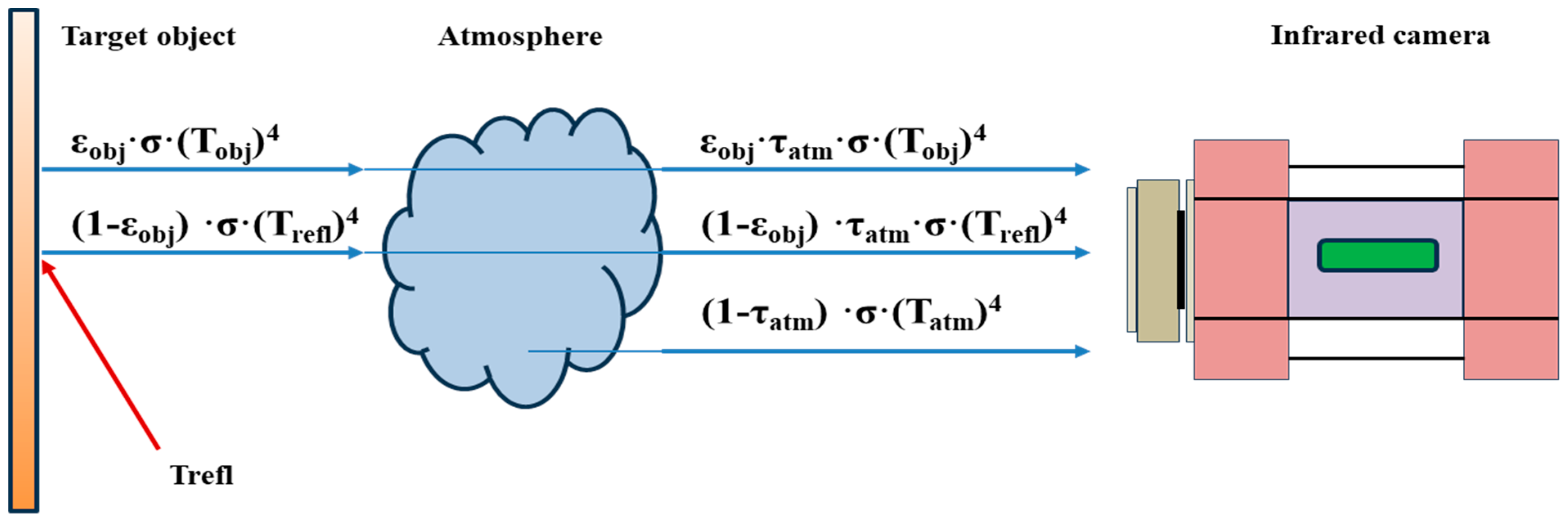
Figure 3.
Moisture detected under the upper hinge of the rudder test sample Reprint with permission from Ref. [54]. 2014, MDPI.
Figure 3.
Moisture detected under the upper hinge of the rudder test sample Reprint with permission from Ref. [54]. 2014, MDPI.
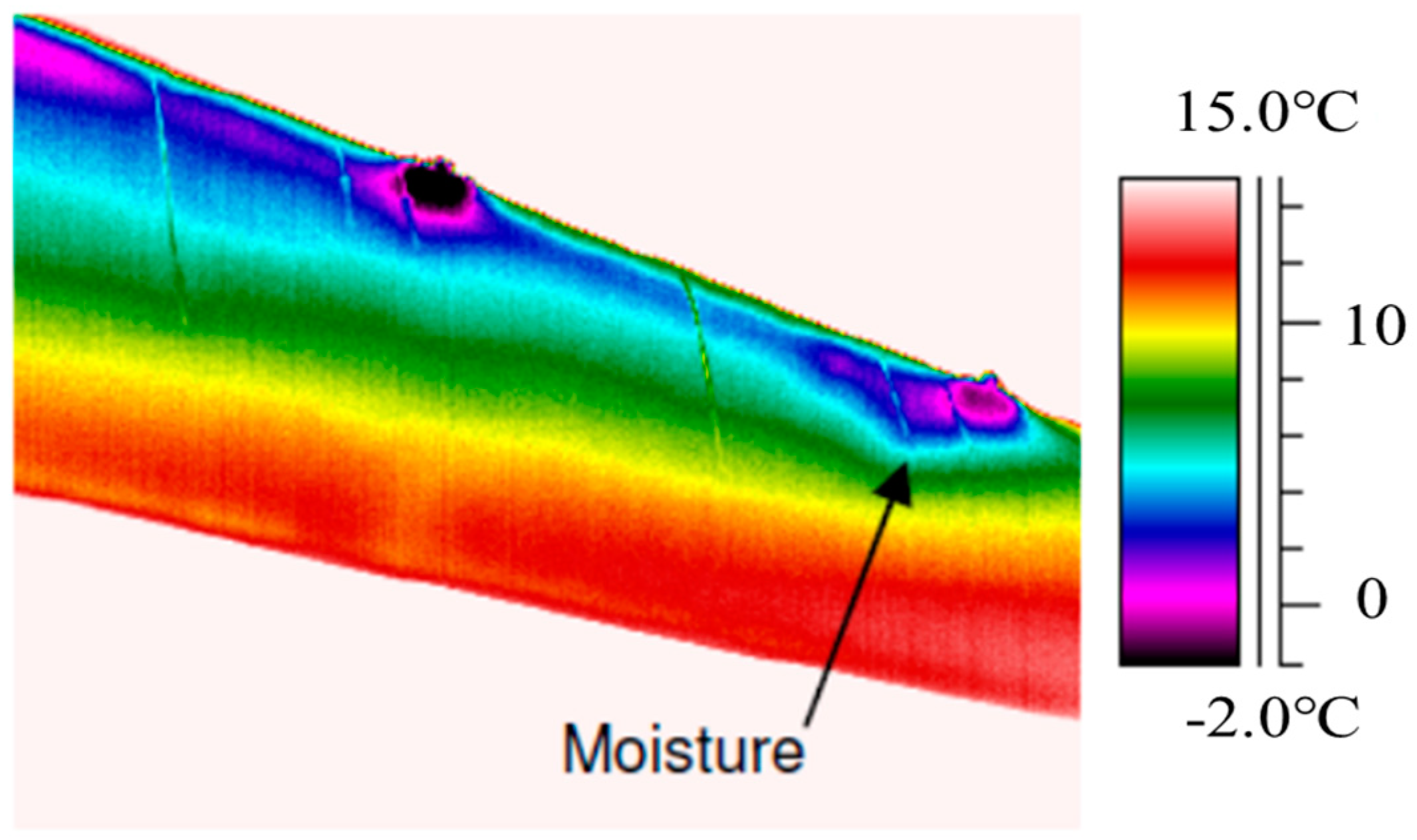
Figure 4.
Microwave reflection and transmission for coated metal (a) and the changes in amplitude (b) and phase (c) microwave detection Reprinted from Ref. [61]. 2013, Elsevier.
Figure 4.
Microwave reflection and transmission for coated metal (a) and the changes in amplitude (b) and phase (c) microwave detection Reprinted from Ref. [61]. 2013, Elsevier.
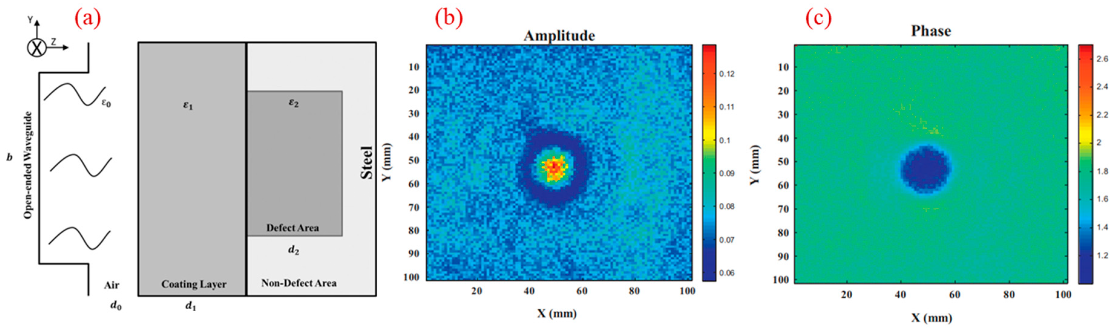
Figure 5.
A typical schematic of the PEC system (a), as well as the measured values and fitted lines of PV(Bnorm) for uncoated and coated corrosion (b) Reprinted with permission from Ref. [35]. 2019, Elsevier and from Ref. [73]. 2012, IEEE.
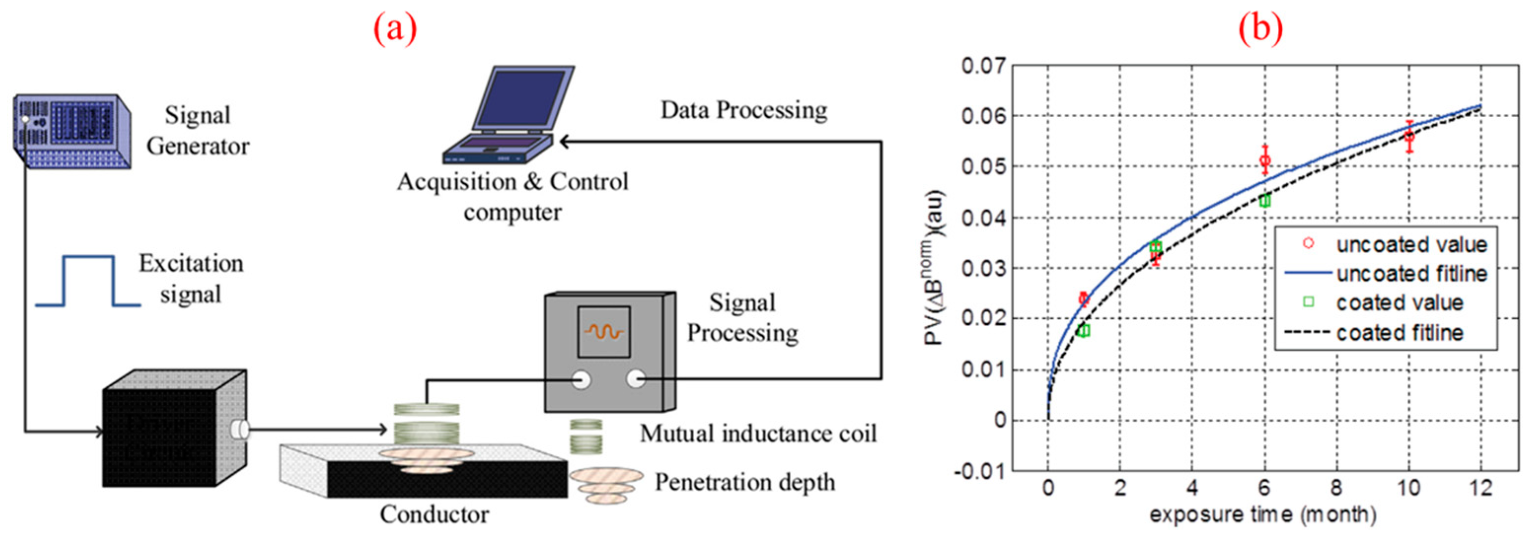
Figure 6.
Experimental setup and the AE measurement system mounted on a small automatic drilling machine Reprint with permission from Ref. [76]. 2024, MDPI.
Figure 6.
Experimental setup and the AE measurement system mounted on a small automatic drilling machine Reprint with permission from Ref. [76]. 2024, MDPI.
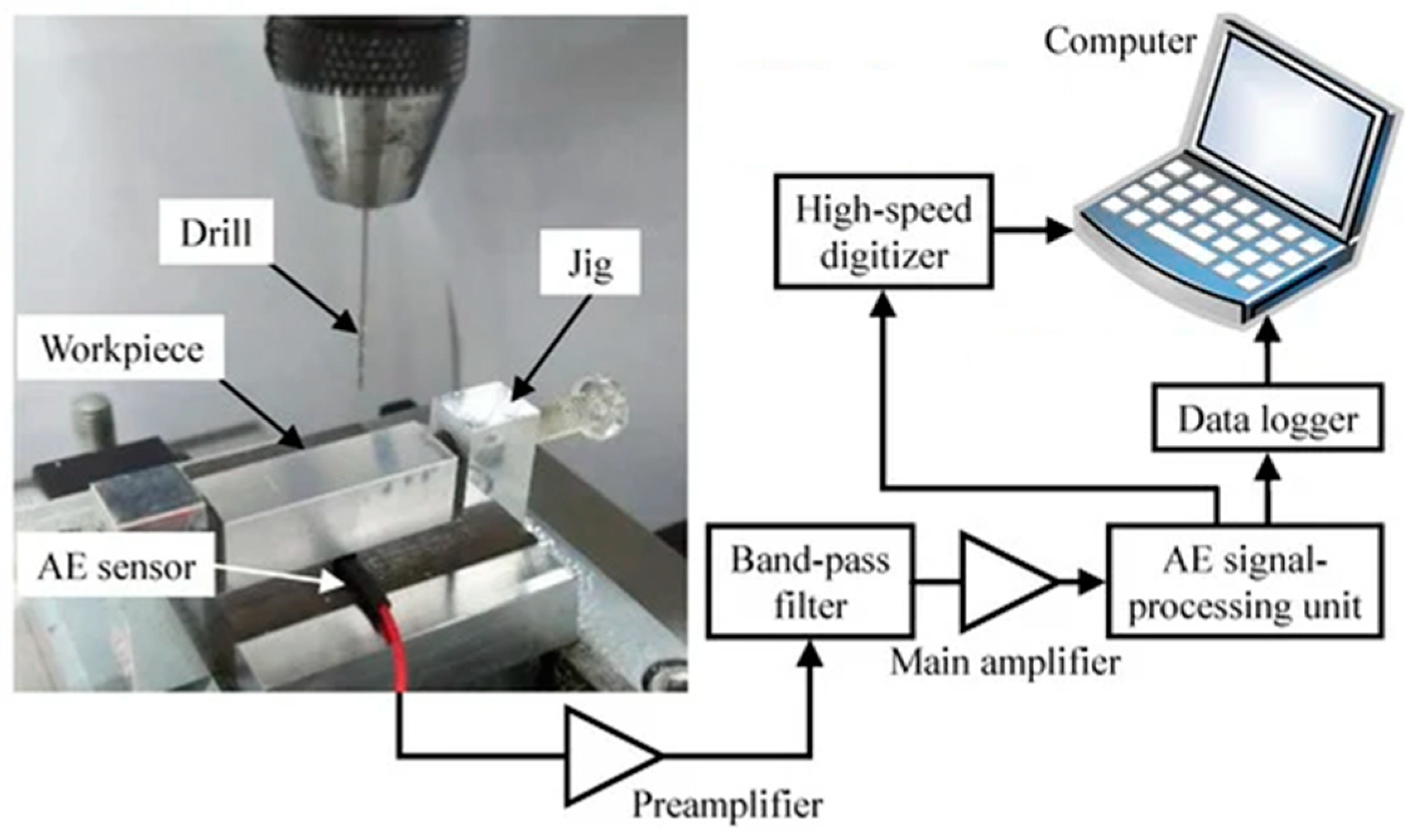
Figure 7.
Schematics of the electrical resistance sensor for corrosion measurement: (a) the measurement circuit and (b) a three-dimensional diagram of the sensitive and compensation elements Reprint with permission from Ref. [88]. 2022, MDPI.
Figure 7.
Schematics of the electrical resistance sensor for corrosion measurement: (a) the measurement circuit and (b) a three-dimensional diagram of the sensitive and compensation elements Reprint with permission from Ref. [88]. 2022, MDPI.
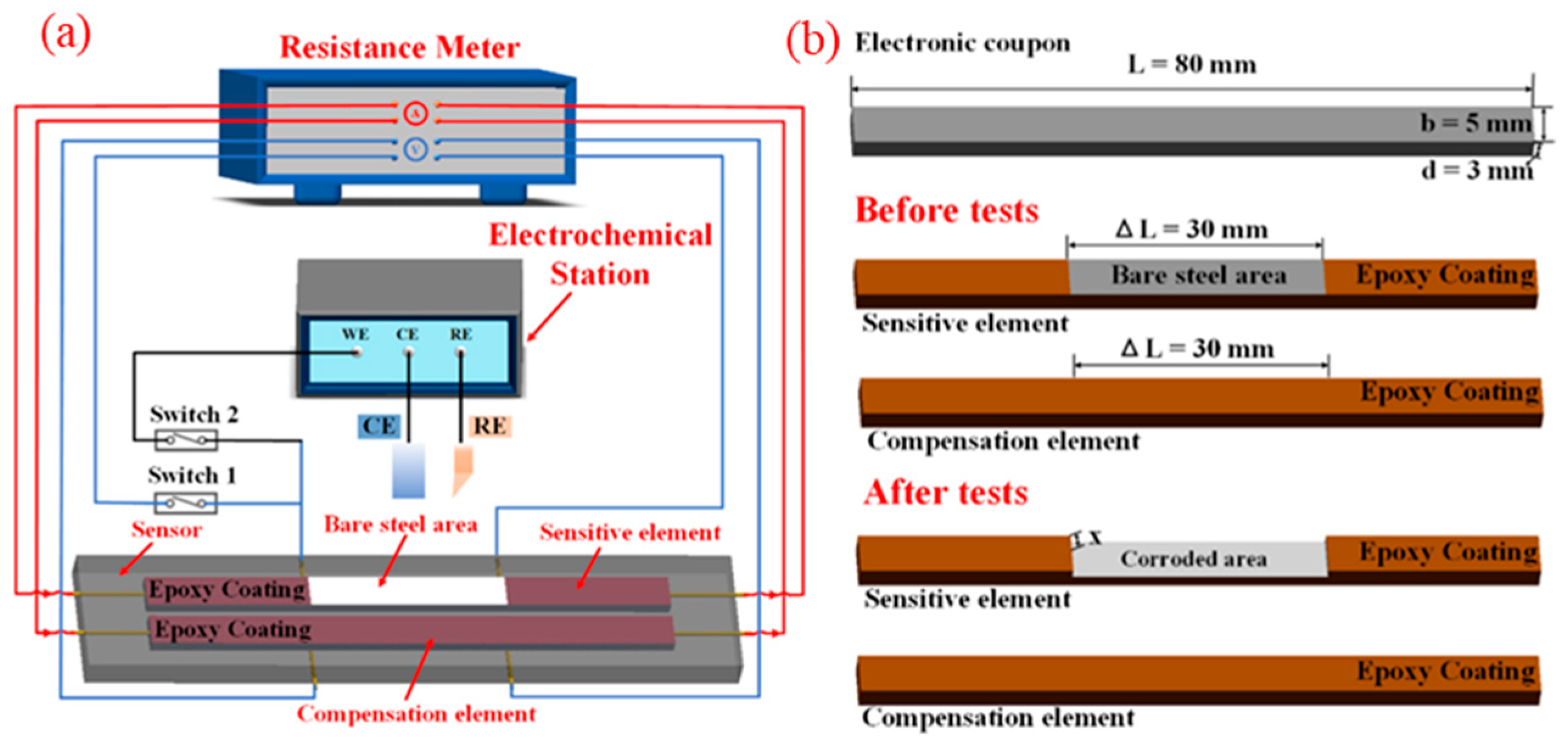
Figure 8.
Typical dependence of ECP (OCP) on (a) pressure at 25 °C and (b) temperature at 10 MPa for Alloy 690 and Alloy 800 Reprinted from Ref. [91]. 2013, Elsevier.
Figure 8.
Typical dependence of ECP (OCP) on (a) pressure at 25 °C and (b) temperature at 10 MPa for Alloy 690 and Alloy 800 Reprinted from Ref. [91]. 2013, Elsevier.

Figure 9.
Typical electrochemical impedance spectroscopy data for (a,b) alloy 690 at 200–300 °C Reprinted from Ref. [105]. 2018, Elsevier and for (c,d) 316L stainless steel in subcritical and supercritical water Reprinted from Ref. [106]. 2019, Elsevier.
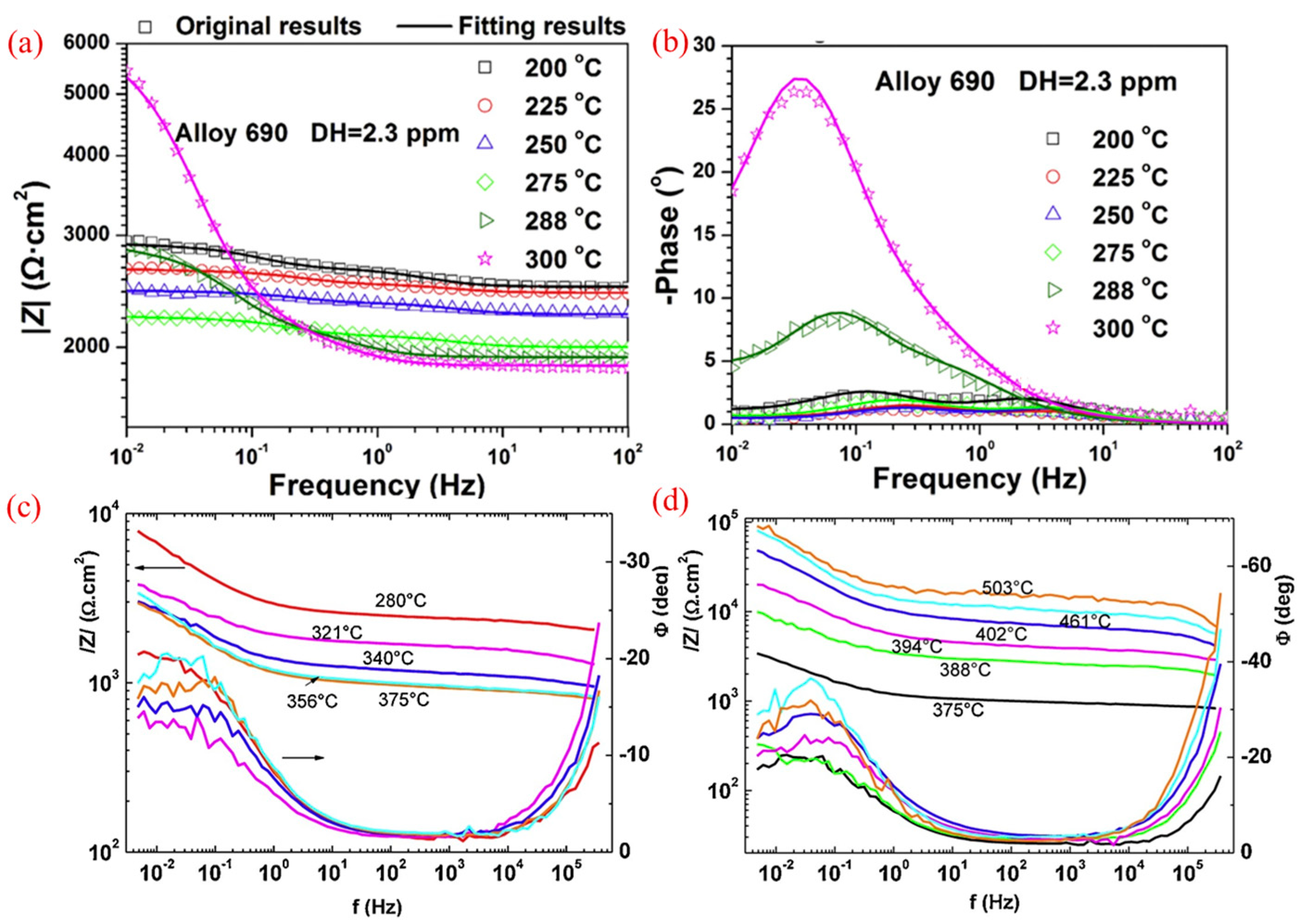
Figure 10.
EN monitoring results of Q235B steel exposed to Tianjin urban atmosphere over 20 days. (a) electrochemical potential noise; (b) electrochemical current noise; (c) relative humidity; (d) temperature; (e) noise resistance; (f) ECN standard deviation; (g) EPN standard deviation Reprinted from Ref. [116]. 2017, SAGE journals.
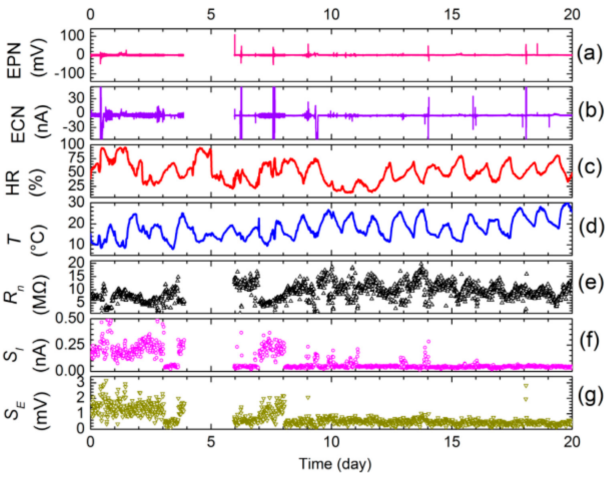
Figure 11.
Once-through recirculating flow loop with hydrodynamic autoclave vessel Reprinted from Ref. [129]. 2010, Elsevier.
Figure 11.
Once-through recirculating flow loop with hydrodynamic autoclave vessel Reprinted from Ref. [129]. 2010, Elsevier.
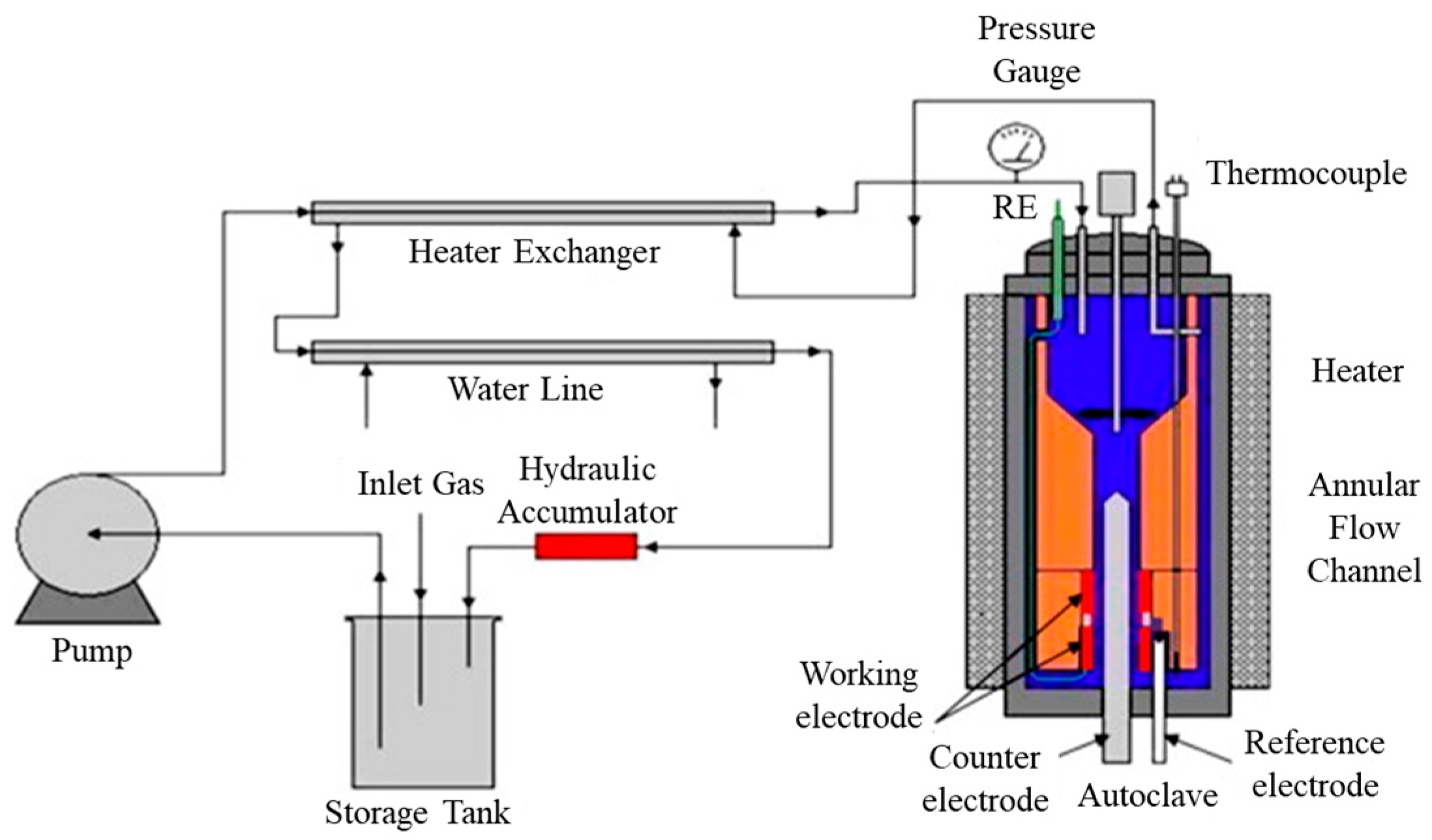
Figure 12.
Schematic diagram of the high-temperature and high-pressure water loop in IMR Reprinted with permission from Ref. [131]. 2017, Elsevier.
Figure 12.
Schematic diagram of the high-temperature and high-pressure water loop in IMR Reprinted with permission from Ref. [131]. 2017, Elsevier.
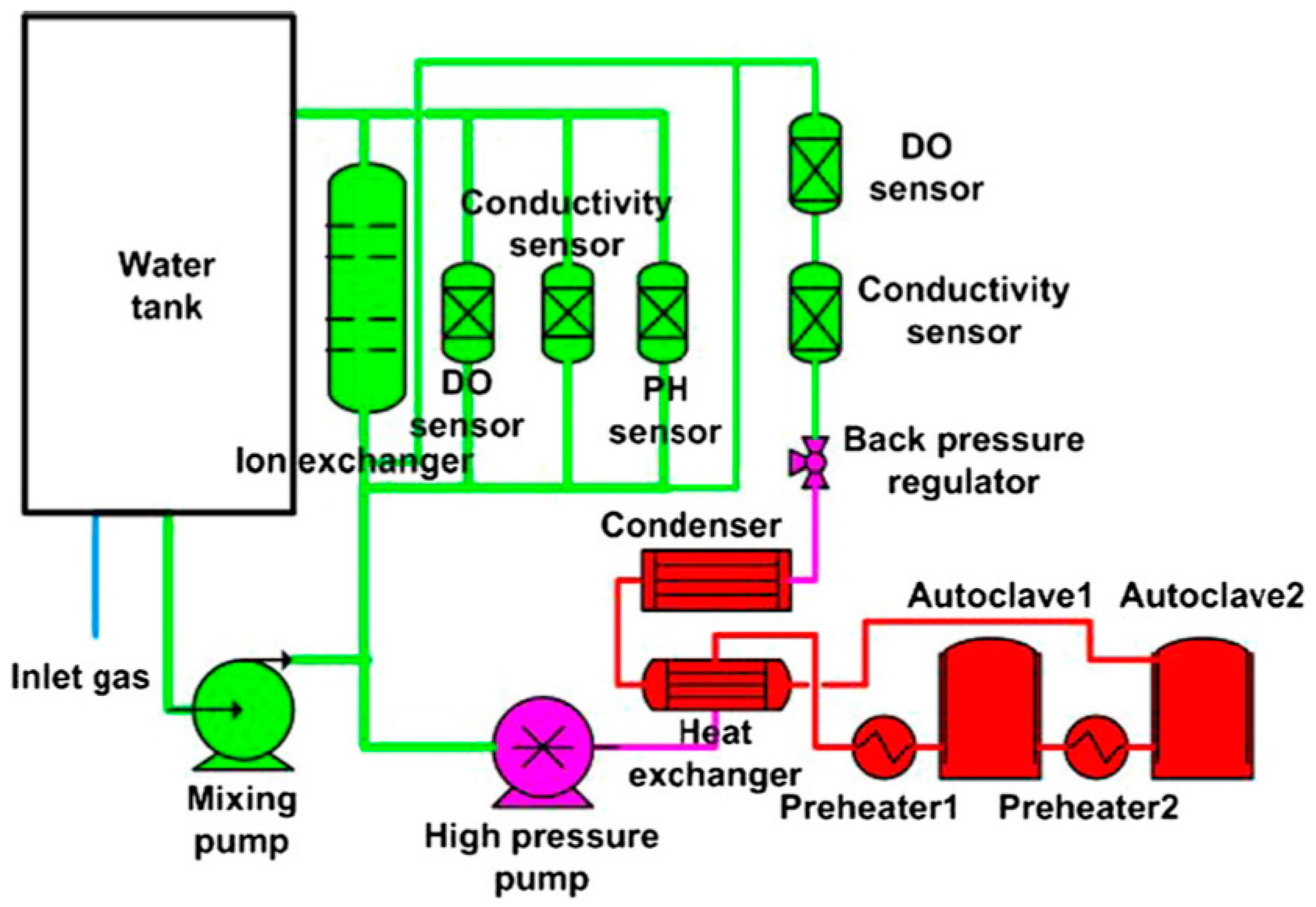
Figure 13.
High-temperature potentiodynamic curves for Alloy 690 at 300 °C (a) in different pH solutions without Zn, (b) in solutions with 1500 ppm B, 2.3 ppm Li, and several Zn concentrations Reprinted with permission from Ref. [134]. 2011, Elsevier.
Figure 13.
High-temperature potentiodynamic curves for Alloy 690 at 300 °C (a) in different pH solutions without Zn, (b) in solutions with 1500 ppm B, 2.3 ppm Li, and several Zn concentrations Reprinted with permission from Ref. [134]. 2011, Elsevier.

Figure 14.
Photo show of a multi-functional sub-/supercritical water electrochemical research platform built in XJTU. (a) the main view of the research platform, (b) autoclave, (c) Reactor base and electrode arrangement.
Figure 14.
Photo show of a multi-functional sub-/supercritical water electrochemical research platform built in XJTU. (a) the main view of the research platform, (b) autoclave, (c) Reactor base and electrode arrangement.

Figure 15.
Change of open circuit potential with temperature (a), variation of the passive current densities with typical anodic potentials and temperatures (b), and Bode diagrams (c) for alloy 690 in lithium borate solutions Reprinted with permission from Ref. [136]. 2019, Elsevier.
Figure 15.
Change of open circuit potential with temperature (a), variation of the passive current densities with typical anodic potentials and temperatures (b), and Bode diagrams (c) for alloy 690 in lithium borate solutions Reprinted with permission from Ref. [136]. 2019, Elsevier.
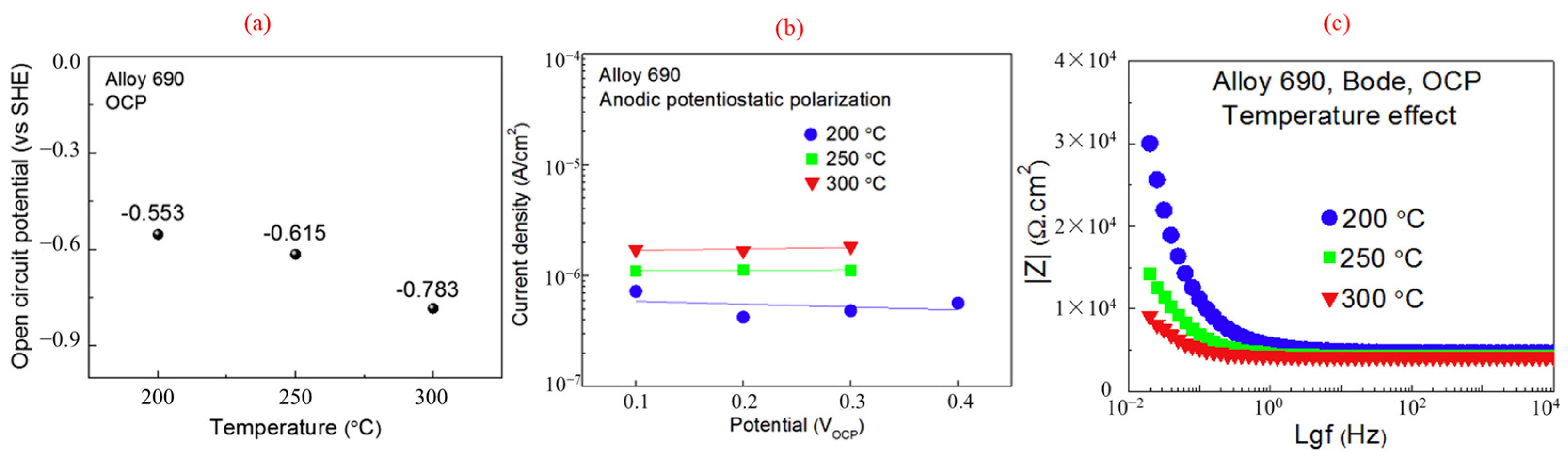

Table 1.
Summary of various non-invasive monitoring methods and their characteristics.
| Monitoring Techniques | Principle | Data Presentation | Advantages | Disadvantages | Application | Error or Accuracy |
|---|---|---|---|---|---|---|
| Ultrasonic measurement [29,30] | Highly sensitive to structural damage; high permeability to materials | Depth of corrosion pits and thickness of corrosion layer | Real-time, suitable for both internal and external corrosion | Not appropriate for small, thin materials | Large-scale testing of oil pipelines and other facilities | Error less than 15% |
| Infrared thermography [31,32] | Recording electromagnetic waves emitted by objects and establishing a clear relationship between temperature and material corrosion defects | Defect size, depth, and thermal characteristics | Reliable, fast, direct, and wide testing range | Required heating and cooling processes; not suitable for thick materials; costly | Extreme temperatures and environments | Affected by changes in the thermal characteristics of objects and environmental conditions |
| Microwave imaging [33,34] | Based on the interaction between microwaves and dielectric materials | The dielectric performance changes caused by defects or structural abnormalities are converted into readable voltage values and then processed and output as images. | Easily accessible to the coated materials. | Have difficulties penetrating conductive materials; it is limited to surface corrosion detection, whereas the deeper corrosion is undetectable. | Determine concrete properties, etc. | Accuracy better than 1/100 of the period length |
| Eddy current detection [35,36] | Detect discontinuities such as corrosion and material loss by monitoring changes in coil impedance or measuring induced magnetic fields. | Depth of corrosion layer, corrosion rate, conductivity and permeability, etc. | It is fast and most commonly used in conductive materials; it is portable and cheap | It is sensitive to skin effects and is surface-oriented. | Suitable for materials of various shapes | Error less than 5% for the thickness of various corrosion [36] |
| Acoustic emission [37,38] | Materials emit transient sound waves locally due to the rapid release of energy. | Deposition of corrosion products, the rupture of passivation films, and the initiation and propagation of cracks | Passive, non-intrusive, low-cost real-time and remote monitoring | Sensitive to background noise | wavelet analysis, modern spectral analysis, and neural network analysis | The accuracy of signal classification is about 65% |
Note: The above accuracy or error data are reference values, and actual monitoring errors are influenced by various factors such as testing methods, properties of the tested item, and environmental factors.
Disclaimer/Publisher’s Note: The statements, opinions and data contained in all publications are solely those of the individual author(s) and contributor(s) and not of MDPI and/or the editor(s). MDPI and/or the editor(s) disclaim responsibility for any injury to people or property resulting from any ideas, methods, instructions or products referred to in the content. |
© 2024 by the authors. Licensee MDPI, Basel, Switzerland. This article is an open access article distributed under the terms and conditions of the Creative Commons Attribution (CC BY) license (https://creativecommons.org/licenses/by/4.0/).
Share and Cite
MDPI and ACS Style
Li, Y.; Bai, Z.; Xing, L.; Zhang, Q.; Ding, S.; Zhang, Y.; Gao, P.; Yu, Z.; Xu, D. Corrosion Monitoring Techniques in Subcritical and Supercritical Water Environments. Appl. Sci. 2024, 14, 2350. https://doi.org/10.3390/app14062350
AMA Style
Li Y, Bai Z, Xing L, Zhang Q, Ding S, Zhang Y, Gao P, Yu Z, Xu D. Corrosion Monitoring Techniques in Subcritical and Supercritical Water Environments. Applied Sciences. 2024; 14(6):2350. https://doi.org/10.3390/app14062350
Chicago/Turabian StyleLi, Yanhui, Zhouyang Bai, Limei Xing, Qian Zhang, Shaoming Ding, Yinan Zhang, Pengfei Gao, Zhihong Yu, and Donghai Xu. 2024. "Corrosion Monitoring Techniques in Subcritical and Supercritical Water Environments" Applied Sciences 14, no. 6: 2350. https://doi.org/10.3390/app14062350
Note that from the first issue of 2016, this journal uses article numbers instead of page numbers. See further details here.